WO2017150001A1 - コンバイナ及びヘッドアップディスプレイ装置 - Google Patents
コンバイナ及びヘッドアップディスプレイ装置 Download PDFInfo
- Publication number
- WO2017150001A1 WO2017150001A1 PCT/JP2017/002211 JP2017002211W WO2017150001A1 WO 2017150001 A1 WO2017150001 A1 WO 2017150001A1 JP 2017002211 W JP2017002211 W JP 2017002211W WO 2017150001 A1 WO2017150001 A1 WO 2017150001A1
- Authority
- WO
- WIPO (PCT)
- Prior art keywords
- fastening
- projection
- combiner
- base
- light image
- Prior art date
- Legal status (The legal status is an assumption and is not a legal conclusion. Google has not performed a legal analysis and makes no representation as to the accuracy of the status listed.)
- Ceased
Links
Images

Classifications
-
- G—PHYSICS
- G02—OPTICS
- G02B—OPTICAL ELEMENTS, SYSTEMS OR APPARATUS
- G02B27/00—Optical systems or apparatus not provided for by any of the groups G02B1/00 - G02B26/00, G02B30/00
- G02B27/01—Head-up displays
- G02B27/0149—Head-up displays characterised by mechanical features
-
- B—PERFORMING OPERATIONS; TRANSPORTING
- B60—VEHICLES IN GENERAL
- B60K—ARRANGEMENT OR MOUNTING OF PROPULSION UNITS OR OF TRANSMISSIONS IN VEHICLES; ARRANGEMENT OR MOUNTING OF PLURAL DIVERSE PRIME-MOVERS IN VEHICLES; AUXILIARY DRIVES FOR VEHICLES; INSTRUMENTATION OR DASHBOARDS FOR VEHICLES; ARRANGEMENTS IN CONNECTION WITH COOLING, AIR INTAKE, GAS EXHAUST OR FUEL SUPPLY OF PROPULSION UNITS IN VEHICLES
- B60K35/00—Instruments specially adapted for vehicles; Arrangement of instruments in or on vehicles
- B60K35/20—Output arrangements, i.e. from vehicle to user, associated with vehicle functions or specially adapted therefor
- B60K35/21—Output arrangements, i.e. from vehicle to user, associated with vehicle functions or specially adapted therefor using visual output, e.g. blinking lights or matrix displays
- B60K35/22—Display screens
-
- B—PERFORMING OPERATIONS; TRANSPORTING
- B60—VEHICLES IN GENERAL
- B60K—ARRANGEMENT OR MOUNTING OF PROPULSION UNITS OR OF TRANSMISSIONS IN VEHICLES; ARRANGEMENT OR MOUNTING OF PLURAL DIVERSE PRIME-MOVERS IN VEHICLES; AUXILIARY DRIVES FOR VEHICLES; INSTRUMENTATION OR DASHBOARDS FOR VEHICLES; ARRANGEMENTS IN CONNECTION WITH COOLING, AIR INTAKE, GAS EXHAUST OR FUEL SUPPLY OF PROPULSION UNITS IN VEHICLES
- B60K35/00—Instruments specially adapted for vehicles; Arrangement of instruments in or on vehicles
- B60K35/20—Output arrangements, i.e. from vehicle to user, associated with vehicle functions or specially adapted therefor
- B60K35/21—Output arrangements, i.e. from vehicle to user, associated with vehicle functions or specially adapted therefor using visual output, e.g. blinking lights or matrix displays
- B60K35/23—Head-up displays [HUD]
- B60K35/231—Head-up displays [HUD] characterised by their arrangement or structure for integration into vehicles
-
- B—PERFORMING OPERATIONS; TRANSPORTING
- B60—VEHICLES IN GENERAL
- B60K—ARRANGEMENT OR MOUNTING OF PROPULSION UNITS OR OF TRANSMISSIONS IN VEHICLES; ARRANGEMENT OR MOUNTING OF PLURAL DIVERSE PRIME-MOVERS IN VEHICLES; AUXILIARY DRIVES FOR VEHICLES; INSTRUMENTATION OR DASHBOARDS FOR VEHICLES; ARRANGEMENTS IN CONNECTION WITH COOLING, AIR INTAKE, GAS EXHAUST OR FUEL SUPPLY OF PROPULSION UNITS IN VEHICLES
- B60K35/00—Instruments specially adapted for vehicles; Arrangement of instruments in or on vehicles
- B60K35/50—Instruments characterised by their means of attachment to or integration in the vehicle
-
- B—PERFORMING OPERATIONS; TRANSPORTING
- B60—VEHICLES IN GENERAL
- B60K—ARRANGEMENT OR MOUNTING OF PROPULSION UNITS OR OF TRANSMISSIONS IN VEHICLES; ARRANGEMENT OR MOUNTING OF PLURAL DIVERSE PRIME-MOVERS IN VEHICLES; AUXILIARY DRIVES FOR VEHICLES; INSTRUMENTATION OR DASHBOARDS FOR VEHICLES; ARRANGEMENTS IN CONNECTION WITH COOLING, AIR INTAKE, GAS EXHAUST OR FUEL SUPPLY OF PROPULSION UNITS IN VEHICLES
- B60K35/00—Instruments specially adapted for vehicles; Arrangement of instruments in or on vehicles
- B60K35/60—Instruments characterised by their location or relative disposition in or on vehicles
-
- B—PERFORMING OPERATIONS; TRANSPORTING
- B60—VEHICLES IN GENERAL
- B60R—VEHICLES, VEHICLE FITTINGS, OR VEHICLE PARTS, NOT OTHERWISE PROVIDED FOR
- B60R11/00—Arrangements for holding or mounting articles, not otherwise provided for
- B60R11/02—Arrangements for holding or mounting articles, not otherwise provided for for radio sets, television sets, telephones, or the like; Arrangement of controls thereof
- B60R11/0229—Arrangements for holding or mounting articles, not otherwise provided for for radio sets, television sets, telephones, or the like; Arrangement of controls thereof for displays, e.g. cathodic tubes
-
- G—PHYSICS
- G02—OPTICS
- G02B—OPTICAL ELEMENTS, SYSTEMS OR APPARATUS
- G02B27/00—Optical systems or apparatus not provided for by any of the groups G02B1/00 - G02B26/00, G02B30/00
- G02B27/01—Head-up displays
-
- G—PHYSICS
- G02—OPTICS
- G02B—OPTICAL ELEMENTS, SYSTEMS OR APPARATUS
- G02B27/00—Optical systems or apparatus not provided for by any of the groups G02B1/00 - G02B26/00, G02B30/00
- G02B27/01—Head-up displays
- G02B27/0101—Head-up displays characterised by optical features
-
- B—PERFORMING OPERATIONS; TRANSPORTING
- B60—VEHICLES IN GENERAL
- B60K—ARRANGEMENT OR MOUNTING OF PROPULSION UNITS OR OF TRANSMISSIONS IN VEHICLES; ARRANGEMENT OR MOUNTING OF PLURAL DIVERSE PRIME-MOVERS IN VEHICLES; AUXILIARY DRIVES FOR VEHICLES; INSTRUMENTATION OR DASHBOARDS FOR VEHICLES; ARRANGEMENTS IN CONNECTION WITH COOLING, AIR INTAKE, GAS EXHAUST OR FUEL SUPPLY OF PROPULSION UNITS IN VEHICLES
- B60K2360/00—Indexing scheme associated with groups B60K35/00 or B60K37/00 relating to details of instruments or dashboards
- B60K2360/20—Optical features of instruments
- B60K2360/33—Illumination features
- B60K2360/334—Projection means
-
- B—PERFORMING OPERATIONS; TRANSPORTING
- B60—VEHICLES IN GENERAL
- B60K—ARRANGEMENT OR MOUNTING OF PROPULSION UNITS OR OF TRANSMISSIONS IN VEHICLES; ARRANGEMENT OR MOUNTING OF PLURAL DIVERSE PRIME-MOVERS IN VEHICLES; AUXILIARY DRIVES FOR VEHICLES; INSTRUMENTATION OR DASHBOARDS FOR VEHICLES; ARRANGEMENTS IN CONNECTION WITH COOLING, AIR INTAKE, GAS EXHAUST OR FUEL SUPPLY OF PROPULSION UNITS IN VEHICLES
- B60K2360/00—Indexing scheme associated with groups B60K35/00 or B60K37/00 relating to details of instruments or dashboards
- B60K2360/60—Structural details of dashboards or instruments
- B60K2360/66—Projection screens or combiners
Definitions
- This disclosure relates to a combiner and a head-up display device.
- HUD device head-up display device
- a head-up display device that displays a display light image from a projection unit onto a combiner such as a deploying mirror so that the display light image is visible to an occupant in the moving body
- Such a combiner of the HUD device is used by being fastened to a base in a moving body as disclosed in, for example, Patent Document 1.
- the base disclosed in Patent Document 1 is provided to be drivable between a plurality of positions.
- This disclosure is intended to provide a combiner and a HUD device that ensure clear visibility of a display light image.
- the combiner according to the first aspect of the present disclosure is fastened to a base in the moving body by a fastening member that forms a planar seating surface, and the display light image is projected from the projection unit, whereby the display light image is displayed. Is displayed as a virtual image so as to be visible from the passenger in the moving body.
- the combiner includes a projection body in which a projection area is set, and both reflection surfaces for reflecting the display light image projected on the projection area to display a virtual image are formed in a curved surface shape.
- the combiner protrudes from the projection main body, and as a fastening protrusion that is fastened to the base by the inserted fastening member, a fastening protrusion that forms a planar fastening surface that comes into surface contact with the seat surface; Is further provided.
- the head-up display device includes a combiner that is fastened to a base in a moving body by a fastening member that forms a planar seating surface.
- the head-up display device projects a display light image from the projection unit onto the combiner, thereby displaying the display light image in a virtual image so that the occupant in the moving body can see the display light image.
- the combiner includes a projection body in which a projection area is set, and both reflection surfaces for reflecting the display light image projected on the projection area to display a virtual image are formed in a curved surface shape.
- the combiner protrudes from the projection main body, and as a fastening protrusion that is fastened to the base by the inserted fastening member, a fastening protrusion that forms a planar fastening surface that comes into surface contact with the seat surface; Is further provided.
- FIG. 4 is a schematic perspective view showing the combiner of FIG. 3. It is a cross-sectional schematic diagram which shows the manufacturing method which manufactures the combiner of FIG. It is a cross-sectional schematic diagram which shows the manufacturing method which manufactures the combiner of FIG.
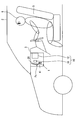
- the HUD device 1 As shown in FIG. 1, the HUD device 1 according to an embodiment of the present disclosure is mounted on a vehicle 2 as a “moving body”.
- the HUD device 1 includes a projection unit 10 and a combiner 20.
- “vertical direction” and “lateral direction” mean “vertical direction” and “horizontal direction” in the vehicle 2 on a horizontal plane, respectively.
- the projection unit 10 is accommodated in the instrument panel 3 in the vehicle 2.
- the projection unit 10 includes a projector 11 and an optical system 12.
- the projector 11 is, for example, a liquid crystal projector or a scanning projector.
- the projector 11 forms an image of the display light image 100 and projects it.
- the optical system 12 includes at least one optical member such as a reflecting mirror.
- the optical system 12 guides the luminous flux of the display light image 100 projected from the projector 11 to the outside of the instrument panel 3 by, for example, reflection. In this way, the light beam is guided by the optical system 12 as shown by the one-dot chain line in FIG.
- the combiner 20 is resin-molded into a plate shape.
- the combiner 20 is fastened to a base 4 provided on the instrument panel 3 in the vehicle 2.
- the combiner 20 is provided so as to be driven together with the base 4.
- the base 4 is driven between the regulation position Pc in FIG. 2 in which the combiner 20 is accommodated in the instrument panel 3 and the allowable position Pp in FIG. 1 in which the combiner 20 is exposed outside the instrument panel 3. Is done.
- Such driving of the base 4 is realized, for example, according to a switch operation or the like by the occupant 6 in the vehicle 2.
- the combiner 20 includes a front reflective surface 21 facing the driver's seat 5 in the vehicle 2 at the permissible position Pp, and a back reflective surface 22 facing the opposite side of the driver's seat 5 (that is, the front outside of the vehicle 2).
- the combiner 20 is formed of, for example, a transparent resin such as an acrylic resin or a semi-transparent resin, thereby exhibiting a light transmission function between the reflection surfaces 21 and 22 and a light reflection function at the reflection surfaces 21 and 22.
- the combiner 20 transmits the luminous flux from the outside image on the outside of the vehicle 2 at the permissible position Pp, so that the outside image can be visually recognized by the occupant 6 seated on the driver's seat 5 in the vehicle 2. .
- the display light image 100 is projected from the optical system 12 of the projection unit 10 onto the combiner 20 at the allowable position Pp.
- the light beam of the display light image 100 is reflected by the reflecting surfaces 21 and 22 as indicated by the one-dot chain line in FIG.
- the light flux reflected by the reflecting surfaces 21 and 22 is incident on the pupil of the occupant 6 seated on the driver seat 5 in the vehicle 2.
- the display light image 100 is visually recognized by the occupant 6 as a virtual image formed on the front outer side of the vehicle 2 with respect to the combiner 20. That is, the display light image 100 is displayed as a virtual image so as to be visible from the occupant 6 in the vehicle 2.
- the display light image 100 is allowed to be viewed from the occupant 6.
- the restricting position Pc in FIG. 2 where the combiner 20 is hidden in the instrument panel 3 the display light image 100 is not projected from the projector 11 and is not projected onto the combiner 20. Visibility from is restricted.
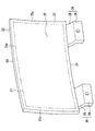
- the combiner 20 includes a projection main body 25 and a pair of fastening protrusions 26.
- the projection main body 25 is formed in a curved plate shape whose outer contour is substantially rectangular.
- the projection main body 25 is curved in each of the vertical direction and the horizontal direction. That is, the curvature is given to the projection main body 25 in both the vertical direction and the horizontal direction.
- the projection main body 25 forms the front reflecting surface 21 in a concave curved surface shape that is concave toward the opposite side to the driver's seat 5 at the permissible position Pp, specifically in a free curved surface shape such as an aspherical shape. ing.
- the projection main body 25 forms the back reflecting surface 22 in a convex curved surface that is convex toward the opposite side to the driver's seat 5 at the permissible position Pp, specifically, a free curved surface such as an aspherical surface. ing.
- these reflection surfaces 21 and 22 increase the plate thickness of the projection main body 25 upward by sandwiching a wedge angle that widens upward.
- a projection region 27 is set in a substantially rectangular portion of the projection main body 25 excluding the outer peripheral edge 25a as schematically shown by a two-dot chain line in FIG.
- the display light image 100 is projected from the projection unit 10 over the entire projection area 27 at the allowable position Pp shown in FIG. That is, the projection area 27 is set as a portion of the projection main body 25 where the display light image 100 is actually projected.
- each fastening protrusion 26 is resin-molded integrally with the projection main body 25.
- Each fastening protrusion 26 is formed in a bent plate shape whose outer shape is substantially rectangular.
- Each fastening protrusion 26 protrudes from two locations spaced apart in the lateral direction in the projection main body 25.
- Each fastening protrusion 26 can be driven together with the base 4 and the projection main body 25 by being fastened to the base 4 as shown in FIG.
- Each fastening protrusion 26 at the allowable position Pp by being fastened to the base 4 protrudes downward from the projection main body 25 outside the instrument panel 3, and is supported from below by the base 4 as a fastening destination. It becomes.
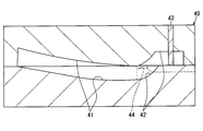
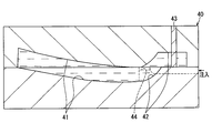
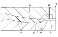
- the combiner 20 in which each fastening protrusion 26 protrudes from the projection main body 25 is manufactured according to the method using the molding die 40 shown in FIGS. Specifically, as shown in FIG. 5, first, the body cavity portion 41 for resin-molding the projection body 25 and the projection cavity portion 42 for resin-molding each fastening projection 26 are closed with the mold 40. To form. At this time, the slide cores 43 are disposed in each of the protrusion cavity portions 42 so as to correspond to insertion holes 29c (see, for example, FIG. 3) serving as insertion portions of the fastening members 30 as described later.
- molten resin is injected into the main body cavity portion 41 from the gate 44 provided between the projection cavity portions 42 in the mold 40.
- the molten resin flows in the cavity portion 41 for main body, so that the molten resin is injected into each projection cavity portion 42 via the cavity portion 41.
- the molten resin is cooled and solidified, whereby the resin-molded combiner 20 is released from the mold 40.
- the projection main body 25 has a gate cut portion 24 corresponding to the gate 44 between the fastening protrusions 26 as shown in FIG.
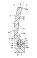
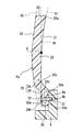
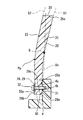
- each of the fastening protrusions 26 fastened to the base 4 by individual fastening members 30 has a relay portion 28 and a fastening portion 29.
- the structure of each fastening protrusion 26 and each fastening member 30 is substantially the same. Therefore, the configuration of the one fastening protrusion 26 and the one fastening member 30 shown in FIG. 3 will be described below.
- the relay portion 28 protrudes from the lower edge portion 25b at the allowable position Pp in the outer peripheral edge portion 25a of the projection main body 25. At the permissible position Pp, the relay portion 28 protrudes obliquely toward the driver's seat 5 as it goes downward from the lower edge portion 25b.
- a pair of virtual extended curved surfaces S1 and S2 that are extended along the reflecting surfaces 21 and 22 to the protruding side of the fastening protrusion 26 are assumed. Under such an assumption, at the location where both virtual extended curved surfaces S1 and S2 pass, the projection body 25 and the fastening portion 29 are relayed by the relay portion 28 protruding from the lower edge portion 25b.
- the fastening portion 29 further protrudes from the lower end portion 28 a at the allowable position Pp of the relay portion 28. At the permissible position Pp, the fastening portion 29 is in a state of protruding straight from the lower edge portion 28a downward.
- a virtual vertical plane Sh extending in the vertical direction is assumed. Under such an assumption, the fastening portion 29 is located on a virtual vertical plane Sh that passes through the center of gravity G of the projection main body 25 only and passes through both lateral edge portions 25c in the lateral direction of the outer peripheral edge portion 25a of the projection main body 25.
- the fastening portion 29 forms a protruding surface 29a and a fastening surface 29b on both sides of the virtual vertical surface Sh passing through the center of gravity G.
- Both the projecting surface 29a and the fastening surface 29b are formed in a planar shape at a location deviating from both of the virtual extended curved surfaces S1 and S2. Under the fastening state of the fastening portion 29 to the base 4, substantially the entire projecting surface 29 a comes into surface contact with the planar base surface 4 a of the base 4.
- the fastening member 30 is made of metal.
- the fastening member 30 has a screw part 31 and a head part 32.
- the screw portion 31 has a male screw shape.
- the screw portion 31 is inserted into an insertion hole 29c that penetrates between the projection surface 29a and the fastening surface 29b in the fastening portion 29.
- the screw portion 31 is screwed into a screw hole 4 b provided in the base 4.
- the head 32 has a disk shape larger in diameter than the screw part 31.
- the head portion 32 forms a planar seating surface 32 a with an annular end surface on the screw portion 31 side.
- the screw part 31 is inserted into the insertion hole 29c and screwed into the screw hole 4b, so that the fastening part 29 is fastened to the base 4 and the fastening surface 29b of the fastening part 29 is seated against the fastening surface 29b.
- the substantially entire surface 32a comes into surface contact.
- the projection main body 25 of the combiner 20 has both the reflection surfaces 21 and 22 that reflect the display light image 100 projected on the projection region 27 and display a virtual image in a curved surface shape. Therefore, in the combiner 20 of the present embodiment, the fastening protrusion 26 that protrudes from the projection main body 25 and is fastened to the base 4 in the vehicle 2 by the fastening member 30 has a flat fastening surface 29b that makes surface contact with the seating surface 32a. Forming.
- the fastening portion 29 of the fastening protrusion 26 is planarly fastened at a place that is disengaged from both of the virtual extended curved surfaces S1 and S2 that are extended along the reflecting surfaces 21 and 22 to the protruding side of the fastening protrusion 26.
- a surface 29b is formed.
- the relay body 28 relays between the projection main body 25 and the fastening portion 29 at a location where both the virtual extended curved surfaces S ⁇ b> 1 and S ⁇ b> 2 along both the reflecting surfaces 21 and 22 pass. .
- the planar fastening surface 29b of the fastening portion 29 is formed at a location that is surely removed from both virtual extended curved surfaces S1 and S2, and the stress propagation rate from the fastening surface 29b to the projection body 25 is reduced. be able to. Therefore, it is possible to ensure high reliability with respect to the effect of ensuring clear visibility of the display light image 100 by suppressing distortion in the projection main body 25.
- the fastening portion 29 of the fastening protrusion 26 is positioned on the virtual vertical plane Sh that extends in the vertical direction and passes through the center of gravity G of the projection main body 25.
- the virtual vertical surface Sh where the fastening projection 26 is located is in a state where the planar fastening surface 29 b is in surface contact with the planar seating surface 32 a of the fastening member 30 and the fastening projection 26 is supported by the base 4.
- the vibration accompanying the vibration of the vehicle 2 can be suppressed to a small level.
- the shaking can be suppressed particularly with respect to the vibration in the front-rear direction generated in the moving vehicle 2. Therefore, it is possible to avoid a situation in which the visibility of the display light image 100 is hindered due to such shaking.
- the fastening portion 29 is placed on the virtual vertical plane Sh passing through the center of gravity G of the projection main body 25. The degree of freedom in design for positioning is increased.
- the fastening protrusions 26 that protrude downward from a plurality of positions in the lateral direction of the projection body 25 are supported from below by the fastening base 4, so that the vibration due to the vibration of the vehicle 2 is shaken.
- the projection body 25 can be kept small. Therefore, it is possible to avoid a situation in which the visibility of the display light image 100 is hindered due to such shaking.
- the fastening protrusion 26 is driven together with the base 4 and the projection main body 25 between the allowable position Pp that allows the display light image 100 to be viewed from the occupant 6 and the restriction position Pc that restricts the visual recognition. For this reason, there is a concern about the shaking of the projection main body 25 accompanying the vibration of the base 4.
- the vibration associated with the vibration of the vehicle 2 but also the vibration associated with the vibration of the base 4 can be suppressed by the projection main body 25, so that the display light image is caused by the vibration. It is possible to avoid the situation where the visibility of 100 is hindered.
- the projection main body 25 that is resin-molded integrally with the fastening protrusion 26 has a gate cut portion 24.
- the resin flow from the gate 44 corresponding to the gate cut portion 24 is caused by the slide core 43 corresponding to the insertion position of the fastening member 30 in the main body cavity portion 41 for resin molding of the projection main body 25. Is less likely to be disturbed. Therefore, it is possible to avoid a situation in which the visibility of the display light image is obstructed by forming defects such as weld lines or sink marks in the projection main body 25 caused by the inhibition of the resin flow.
- the fastening protrusion 26 can be fastened by the planar fastening surface 29b in surface contact with the planar seating surface 32a of the fastening member 30 or the planar projection surface 29a in surface contact with the planar base surface 4a of the base 4.
- the planar fastening surface 29b in surface contact with the planar seating surface 32a of the fastening member 30 or the planar projection surface 29a in surface contact with the planar base surface 4a of the base 4.
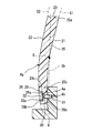
- a fastening surface 29b of the fastening protrusion 26 may be formed at a location where at least one of the virtual extended curved surfaces S1 and S2 passes as shown in FIG.
- the fastening surface 29b of the fastening protrusion 26 is formed on the virtual extended curved surface S1 along the front reflecting surface 21 on the driver's seat 5 side.
- the fastening protrusion 26 is fastened by the flat bottom surface of the concave portion 26 a at a position deviated from the virtual extended curved surface S ⁇ b> 2 along the back reflection surface 22 on the side opposite to the driver seat 5.
- the surface 29b may be formed.
- the fastening surface 29 b of the fastening protrusion 26 is formed by a planar plate surface at a location continuing from the virtual extended curved surface S ⁇ b> 2 along the back reflection surface 22 on the side opposite to the driver seat 5. May be formed.
- a projection surface 29a of the fastening projection 26 may be formed at a location where at least one of the virtual extended curved surfaces S1 and S2 passes.
- the projection surface 29a of the fastening protrusion 26 is formed on virtual extension curved surface S1 in alignment with the front reflective surface 21 at the side of the driver's seat 5.
- the base surface 4a of the base 4 is formed in a curved shape
- the projection surface 29a of the fastening projection 26 is formed in a curved shape that complements the base surface 4a. May be.
- a fastening portion 29 of the fastening protrusion 26 may be formed at a location deviating from the virtual vertical plane Sh passing through the center of gravity G of only the projection main body 25.
- the fastening portion 29 may be protruded directly from the projection main body 25 without providing the fastening projection 26 with the relay portion 28.
- the relay portion 28 may be protruded obliquely toward the opposite side of the driver seat 5 as it goes downward from the lower edge portion 25b of the projection main body 25.
- the fastening protrusions 26 may be protruded from one place or three or more places in the horizontal direction of the projection main body 25. As a tenth modification, the fastening protrusions 26 may protrude from one or a plurality of locations in the vertical direction of the projection main body 25.
- the base 4 may be fixed to the instrument panel 3.
- the base 4 may be rotationally driven between the allowable position Pp and the restricting position Pc around the rotation axis.
- a part of the combiner 20 may be formed of a material other than resin.
- a fastening protrusion 26 having a gate cut portion 24 may be employed.
- the projection area 27 may be set over the entire area of the projection main body 25.
- the thickness of the projection main body 25 may be set to be substantially constant over at least the entire projection region 27 without interposing a wedge angle between the reflecting surfaces 21 and 22.
- at least one of the reflecting surfaces 21 and 22 may be curved only in one of the vertical direction and the horizontal direction.
- the display light image 100 may be directly projected from the projector 11 to the combiner 20 without providing the optical system 12 in the projection unit 10.
- the present disclosure may be applied to HUD devices and combiners that are mounted on various “moving bodies” such as ships or airplanes other than the vehicle 2.
- the above-described combiner 20 is fastened to the base 4 in the moving body 2 by the fastening member 30 that forms the planar seating surface 32a, and the display light image 100 is projected from the projection unit 10, thereby displaying light.
- the image is displayed as a virtual image so as to be visible from the occupant 6 in the moving body.
- the projection main body 25 has a projection area 27, and both reflection surfaces 21 and 22 for reflecting a display light image projected on the projection area and displaying a virtual image are formed in a curved surface shape.
- the fastening protrusion protrudes from the projection main body, and forms a flat fastening surface 29b that comes into surface contact with the seat surface as the fastening protrusion 26 fastened to the base by the inserted fastening member.
- the head-up display device 1 described above includes the combiner 20 that is fastened to the base 4 in the moving body 2 by the fastening member 30 that forms the planar seating surface 32a, and displays from the projection unit 10 to the combiner.
- the combiner includes a projection main body 25 and a fastening protrusion.
- the projection main body 25 has a projection area 27, and both reflection surfaces 21 and 22 for reflecting a display light image projected on the projection area and displaying a virtual image are formed in a curved surface shape.
- the fastening protrusion protrudes from the projection main body, and forms a flat fastening surface 29b that comes into surface contact with the seat surface as the fastening protrusion 26 fastened to the base by the inserted fastening member.
- the projection main body of the combiner is formed in a curved surface with both reflection surfaces for reflecting the display light image projected on the projection area and displaying a virtual image. Therefore, in the combiners disclosed in the first and second disclosures, the fastening protrusions protruding from the projection main body and fastened to the base in the moving body by the fastening members form a flat fastening surface that comes into surface contact with the seating surface. According to this, the fastening projection receiving the fastening stress at the planar fastening surface that is in surface contact with the planar seating surface of the fastening member is not easily distorted, but also on the projection main body from which the fastening projection is projected. Is difficult to propagate such fastening stress. Therefore, distortion can be prevented from occurring in the projection body where the projection area is set, so that it is possible to ensure clear visibility of the display light image that is reflected on both reflection surfaces in the projection area and displayed as a virtual image. It becomes.
Landscapes
- Engineering & Computer Science (AREA)
- Mechanical Engineering (AREA)
- Physics & Mathematics (AREA)
- Chemical & Material Sciences (AREA)
- Combustion & Propulsion (AREA)
- Transportation (AREA)
- General Physics & Mathematics (AREA)
- Optics & Photonics (AREA)
- Instrument Panels (AREA)
- Fittings On The Vehicle Exterior For Carrying Loads, And Devices For Holding Or Mounting Articles (AREA)
Priority Applications (3)
| Application Number | Priority Date | Filing Date | Title |
|---|---|---|---|
| DE112017001050.0T DE112017001050T5 (de) | 2016-02-29 | 2017-01-24 | Kombinationseinrichtung und Head-up-Display-Vorrichtung |
| KR1020187023250A KR102108166B1 (ko) | 2016-02-29 | 2017-01-24 | 컴바이너 및 헤드업 디스플레이 장치 |
| US16/080,031 US10859827B2 (en) | 2016-02-29 | 2017-01-24 | Combiner and head-up display device |
Applications Claiming Priority (2)
| Application Number | Priority Date | Filing Date | Title |
|---|---|---|---|
| JP2016037256A JP6390641B2 (ja) | 2016-02-29 | 2016-02-29 | コンバイナ及びヘッドアップディスプレイ装置 |
| JP2016-037256 | 2016-02-29 |
Publications (1)
| Publication Number | Publication Date |
|---|---|
| WO2017150001A1 true WO2017150001A1 (ja) | 2017-09-08 |
Family
ID=59743761
Family Applications (1)
| Application Number | Title | Priority Date | Filing Date |
|---|---|---|---|
| PCT/JP2017/002211 Ceased WO2017150001A1 (ja) | 2016-02-29 | 2017-01-24 | コンバイナ及びヘッドアップディスプレイ装置 |
Country Status (5)
| Country | Link |
|---|---|
| US (1) | US10859827B2 (enExample) |
| JP (1) | JP6390641B2 (enExample) |
| KR (1) | KR102108166B1 (enExample) |
| DE (1) | DE112017001050T5 (enExample) |
| WO (1) | WO2017150001A1 (enExample) |
Families Citing this family (4)
| Publication number | Priority date | Publication date | Assignee | Title |
|---|---|---|---|---|
| KR102035136B1 (ko) * | 2018-01-18 | 2019-10-22 | 엘지전자 주식회사 | 차량용 헤드업 디스플레이 장치 |
| JP7257622B2 (ja) * | 2019-07-26 | 2023-04-14 | パナソニックIpマネジメント株式会社 | ヘッドアップディスプレイ、表示媒体 |
| JP2024071852A (ja) | 2022-11-15 | 2024-05-27 | 日亜化学工業株式会社 | 映像表示装置 |
| JP2024081036A (ja) * | 2022-12-05 | 2024-06-17 | 日亜化学工業株式会社 | 光源ユニット及び映像表示装置 |
Citations (3)
| Publication number | Priority date | Publication date | Assignee | Title |
|---|---|---|---|---|
| JPH1172742A (ja) * | 1997-08-29 | 1999-03-16 | Shimadzu Corp | ヘッドアップディスプレイ |
| JP2015087202A (ja) * | 2013-10-30 | 2015-05-07 | 日本精機株式会社 | 車両用表示装置及び車載システム |
| JP2015212780A (ja) * | 2014-05-07 | 2015-11-26 | 日本精機株式会社 | 車両用ヘッドアップディスプレイ装置 |
Family Cites Families (8)
| Publication number | Priority date | Publication date | Assignee | Title |
|---|---|---|---|---|
| JP4387608B2 (ja) * | 2001-03-30 | 2009-12-16 | 矢崎総業株式会社 | 車両表示システム用コンバイナの支持装置 |
| WO2008135261A1 (fr) | 2007-05-04 | 2008-11-13 | Johnson Controls Gmbh | Dispositif d'affichage |
| EP2832588B1 (en) * | 2012-03-29 | 2018-11-21 | Nippon Seiki Co., Ltd. | Combiner storage device, head-up display device |
| JP6349632B2 (ja) * | 2013-06-24 | 2018-07-04 | 日本精機株式会社 | ヘッドアップディスプレイ装置 |
| WO2015019401A1 (ja) * | 2013-08-05 | 2015-02-12 | パイオニア株式会社 | 虚像表示装置 |
| JP6327052B2 (ja) | 2014-08-11 | 2018-05-23 | スズキ株式会社 | 電動船外機 |
| WO2016208529A1 (ja) * | 2015-06-26 | 2016-12-29 | コニカミノルタ株式会社 | ヘッドアップディスプレイ装置 |
| JP6575855B2 (ja) * | 2015-06-29 | 2019-09-18 | パナソニックIpマネジメント株式会社 | 車載用コンバイナ昇降装置および車載用ヘッドアップディスプレイ装置 |
-
2016
- 2016-02-29 JP JP2016037256A patent/JP6390641B2/ja active Active
-
2017
- 2017-01-24 DE DE112017001050.0T patent/DE112017001050T5/de not_active Ceased
- 2017-01-24 US US16/080,031 patent/US10859827B2/en active Active
- 2017-01-24 WO PCT/JP2017/002211 patent/WO2017150001A1/ja not_active Ceased
- 2017-01-24 KR KR1020187023250A patent/KR102108166B1/ko not_active Expired - Fee Related
Patent Citations (3)
| Publication number | Priority date | Publication date | Assignee | Title |
|---|---|---|---|---|
| JPH1172742A (ja) * | 1997-08-29 | 1999-03-16 | Shimadzu Corp | ヘッドアップディスプレイ |
| JP2015087202A (ja) * | 2013-10-30 | 2015-05-07 | 日本精機株式会社 | 車両用表示装置及び車載システム |
| JP2015212780A (ja) * | 2014-05-07 | 2015-11-26 | 日本精機株式会社 | 車両用ヘッドアップディスプレイ装置 |
Also Published As
| Publication number | Publication date |
|---|---|
| US10859827B2 (en) | 2020-12-08 |
| JP2017154529A (ja) | 2017-09-07 |
| JP6390641B2 (ja) | 2018-09-19 |
| US20190061638A1 (en) | 2019-02-28 |
| KR20180103113A (ko) | 2018-09-18 |
| KR102108166B1 (ko) | 2020-05-08 |
| DE112017001050T5 (de) | 2018-12-06 |
Similar Documents
| Publication | Publication Date | Title |
|---|---|---|
| TWI541543B (zh) | 分光模組及應用其之投影裝置 | |
| JP6558017B2 (ja) | ヘッドアップディスプレイ | |
| JP6390641B2 (ja) | コンバイナ及びヘッドアップディスプレイ装置 | |
| JP6995883B2 (ja) | ヘッドアップディスプレイ装置 | |
| JP6963732B2 (ja) | ヘッドアップディスプレイ装置 | |
| US20180231774A1 (en) | Head-up display device | |
| KR102087800B1 (ko) | 허상 표시 장치 | |
| WO2015122473A1 (ja) | ヘッドアップディスプレイ装置 | |
| JP2014115417A (ja) | ヘッドアップディスプレイ装置 | |
| JP2018165061A (ja) | ヘッドアップディスプレイ装置 | |
| JP2017067924A (ja) | ヘッドアップディスプレイ装置 | |
| JP2015072422A (ja) | 車両用表示装置 | |
| CN110300915A (zh) | 虚像显示装置 | |
| JP2018132685A (ja) | ヘッドアップディスプレイ装置 | |
| JP6969424B2 (ja) | 平面鏡ユニット | |
| JP2018530771A (ja) | コンパクトなヘッドアップディスプレイ | |
| JP2017190056A (ja) | ヘッドアップディスプレイ装置 | |
| EP3327484B1 (en) | Reflection protection for a head up display system | |
| JP2018055038A (ja) | ヘッドアップディスプレイ装置のミラーユニット | |
| JP3219059U (ja) | 光学投影装置 | |
| JP6664555B2 (ja) | ヘッドアップディスプレイ装置 | |
| JP7383948B2 (ja) | ヘッドアップディスプレイ | |
| CN110312958A (zh) | 虚像显示装置 | |
| JP7064686B2 (ja) | ヘッドアップディスプレイ装置 | |
| JP2015229431A (ja) | 車両用情報表示装置、車両用情報表示装置を備えた車両及び車両用情報の表示方法 |
Legal Events
| Date | Code | Title | Description |
|---|---|---|---|
| ENP | Entry into the national phase |
Ref document number: 20187023250 Country of ref document: KR Kind code of ref document: A |
|
| WWE | Wipo information: entry into national phase |
Ref document number: 1020187023250 Country of ref document: KR |
|
| 121 | Ep: the epo has been informed by wipo that ep was designated in this application |
Ref document number: 17759473 Country of ref document: EP Kind code of ref document: A1 |
|
| 122 | Ep: pct application non-entry in european phase |
Ref document number: 17759473 Country of ref document: EP Kind code of ref document: A1 |