WO2017149760A1 - 気体排出量の推定方法 - Google Patents
気体排出量の推定方法 Download PDFInfo
- Publication number
- WO2017149760A1 WO2017149760A1 PCT/JP2016/056799 JP2016056799W WO2017149760A1 WO 2017149760 A1 WO2017149760 A1 WO 2017149760A1 JP 2016056799 W JP2016056799 W JP 2016056799W WO 2017149760 A1 WO2017149760 A1 WO 2017149760A1
- Authority
- WO
- WIPO (PCT)
- Prior art keywords
- gas
- storage tank
- amount
- liquid
- relief valve
- Prior art date
- Legal status (The legal status is an assumption and is not a legal conclusion. Google has not performed a legal analysis and makes no representation as to the accuracy of the status listed.)
- Ceased
Links
Images




Classifications
-
- G—PHYSICS
- G01—MEASURING; TESTING
- G01F—MEASURING VOLUME, VOLUME FLOW, MASS FLOW OR LIQUID LEVEL; METERING BY VOLUME
- G01F22/00—Methods or apparatus for measuring volume of fluids or fluent solid material, not otherwise provided for
- G01F22/02—Methods or apparatus for measuring volume of fluids or fluent solid material, not otherwise provided for involving measurement of pressure
-
- B—PERFORMING OPERATIONS; TRANSPORTING
- B65—CONVEYING; PACKING; STORING; HANDLING THIN OR FILAMENTARY MATERIAL
- B65D—CONTAINERS FOR STORAGE OR TRANSPORT OF ARTICLES OR MATERIALS, e.g. BAGS, BARRELS, BOTTLES, BOXES, CANS, CARTONS, CRATES, DRUMS, JARS, TANKS, HOPPERS, FORWARDING CONTAINERS; ACCESSORIES, CLOSURES, OR FITTINGS THEREFOR; PACKAGING ELEMENTS; PACKAGES
- B65D90/00—Component parts, details or accessories for large containers
-
- F—MECHANICAL ENGINEERING; LIGHTING; HEATING; WEAPONS; BLASTING
- F17—STORING OR DISTRIBUTING GASES OR LIQUIDS
- F17C—VESSELS FOR CONTAINING OR STORING COMPRESSED, LIQUEFIED OR SOLIDIFIED GASES; FIXED-CAPACITY GAS-HOLDERS; FILLING VESSELS WITH, OR DISCHARGING FROM VESSELS, COMPRESSED, LIQUEFIED, OR SOLIDIFIED GASES
- F17C13/00—Details of vessels or of the filling or discharging of vessels
- F17C13/02—Special adaptations of indicating, measuring, or monitoring equipment
-
- F—MECHANICAL ENGINEERING; LIGHTING; HEATING; WEAPONS; BLASTING
- F16—ENGINEERING ELEMENTS AND UNITS; GENERAL MEASURES FOR PRODUCING AND MAINTAINING EFFECTIVE FUNCTIONING OF MACHINES OR INSTALLATIONS; THERMAL INSULATION IN GENERAL
- F16C—SHAFTS; FLEXIBLE SHAFTS; ELEMENTS OR CRANKSHAFT MECHANISMS; ROTARY BODIES OTHER THAN GEARING ELEMENTS; BEARINGS
- F16C13/00—Rolls, drums, discs, or the like; Bearings or mountings therefor
- F16C13/02—Bearings
- F16C13/022—Bearings supporting a hollow roll mantle rotating with respect to a yoke or axle
- F16C13/024—Bearings supporting a hollow roll mantle rotating with respect to a yoke or axle adjustable for positioning, e.g. radial movable bearings for controlling the deflection along the length of the roll mantle
- F16C13/026—Bearings supporting a hollow roll mantle rotating with respect to a yoke or axle adjustable for positioning, e.g. radial movable bearings for controlling the deflection along the length of the roll mantle by fluid pressure
-
- G—PHYSICS
- G01—MEASURING; TESTING
- G01F—MEASURING VOLUME, VOLUME FLOW, MASS FLOW OR LIQUID LEVEL; METERING BY VOLUME
- G01F23/00—Indicating or measuring liquid level or level of fluent solid material, e.g. indicating in terms of volume or indicating by means of an alarm
- G01F23/14—Indicating or measuring liquid level or level of fluent solid material, e.g. indicating in terms of volume or indicating by means of an alarm by measurement of pressure
Definitions
- the present invention relates to a technique for estimating the amount of gas discharged from a relief valve provided in a storage tank that stores a liquid containing a volatile substance.
- a gas phase space is formed on the upper side of the liquid (liquid phase) stored in the storage tank.
- the amount of gas evaporation from the liquid surface increases, and the pressure of the gas in the gas phase space rises.
- the gas in the space is Is provided with a relief valve (for example, FIG. 1 of Patent Document 1).
- VOC Volatile Organic Compounds
- a VOC recovery device that recovers VOC in the gas discharged from the relief valve may be provided from the viewpoint of environmental protection and the like.
- the temperature in the storage tank changes daily depending on the weather conditions, etc., and in the storage tank even within a day, depending on the presence or absence of daylight and nighttime, and the change in the amount of sunlight due to daytime sun movement.
- the temperature of the gas and the pressure in the gas phase space change every moment. For this reason, it is difficult to accurately grasp the amount of gas discharged from the relief valve.
- VOC recovery is based on the instantaneous discharge amount from the relief valve stipulated in industrial standards such as API (American Petroleum Institute) 2000. Designed exhaust gas handling capacity in the equipment.
- the relief valve specifications stipulated in the industry standard are for vaporization of gas generated under the harshest conditions without taking into account the difference in the storage tank installation area and the heat transfer characteristics of the storage tank body (for example, whether heat is retained). Since the volume is based, there is a tendency that the capacity of the VOC recovery device provided in the storage tank becomes excessive compared with the actual gas discharge amount.
- the present invention has been made under such a background, and an object of the present invention is to estimate a gas emission amount more accurately from a fixed roof storage tank storing a liquid containing a volatile substance.
- the purpose is to provide a method for estimating emissions.
- the method for estimating gas emissions of the present invention is a method for estimating gas emissions from a storage tank storing a liquid containing a volatile substance, (A) tank shape of a fixed roof type storage tank provided with a relief valve; (b) operating pressure of the relief valve; (c) thermodynamic properties of the liquid in the storage tank; A first step of setting preconditions relating to the thermodynamic properties of the gas in the storage tank; A second step of setting initial conditions of internal volume, temperature, and pressure for each of the liquid and gas in the storage tank; The inflow heat quantity or the outflow heat quantity with respect to the liquid and gas through the partition wall of the storage tank is determined, and the temperature change of the liquid and gas and the change of gas-liquid equilibrium state are calculated by numerical fluid dynamic analysis, A third step of determining the amount of mass transfer between liquid and gas; A change in pressure of the gas is obtained based on the amount of mass transfer, and when the changed gas pressure exceeds the operating pressure of the relief valve, a discharge amount of the gas discharged from the relief valve is obtained. And 4
- the method for estimating the gas discharge amount may have the following characteristics.
- the relief valve includes a discharge vent, and the gas discharged from the relief valve is discharged toward a recovery device for a volatile substance contained in the gas via the discharge vent.
- the storage tank includes a suction valve.
- the operating pressure of the suction valve is set, and in the fourth step, after the pressure change If the pressure of the gas is lower than the operating pressure of the suction valve, obtain the amount of gas sucked from the suction valve.
- the suction valve includes a suction vent, and the gas sucked from the suction valve is an inert gas supplied through the suction vent.
- Gas discharged from the relief valve by repeating the third step and the fourth step, setting a new initial condition in the second step, and then executing the third step and the fourth step To determine the change over time in the amount of gas discharged.
- the maximum discharge flow rate per unit time or the total discharge amount of gas discharged within a preset period is obtained based on the change over time of the discharge amount of the gas discharged from the relief valve. thing.
- the inflow heat amount or outflow heat amount for the liquid and gas determined in the third step is determined based on thermal energy supplied from sunlight to the storage tank through the partition wall. The thermal energy supplied from the sunlight is determined by the longitude and latitude of the point where the storage tank is installed and the calendar date.
- the gas in the storage tank contains the volatile substance and other substances, and the mass transfer amount between the liquid and gas determined in the third step, and the fourth step The amount of the volatile substance discharged is calculated based on the amount of the gas discharged determined in step 1.
- the present invention specifies the amount of mass transfer between liquid and gas in the storage tank based on the inflow heat amount and the outflow heat amount with respect to the liquid containing the volatile substance stored in the storage tank, and based on this mass transfer amount. Since the gas discharge amount from the relief valve is obtained, an accurate gas discharge amount can be grasped.
- FIG. 1 schematically shows a storage tank 1 for liquid that is a target for estimating the amount of gas discharged.
- the storage tank 1 is configured as a container in which the upper and lower surfaces of the cylindrical side wall portion 102 are closed with a fixed roof portion 103 and a bottom plate portion 101, respectively.
- the storage tank 1 is not particularly limited in its shape, except that the fixed roof portion 103 is a fixed roof type in which the fixed roof portion 103 is fixed to the upper side of the side wall portion 102.
- the fixed roof portion 103 may be a dome roof, a cone roof, or other shapes.
- the storage tank 1 may have a rectangular parallelepiped shape, or may be a horizontal type in which the axis of a cylindrical container is oriented in the horizontal direction.
- FIG. 1 shows an example of a storage tank 1 in which a fixed roof portion 103 having a dome roof shape is provided on the upper surface of a cylindrical side wall portion 102.
- the storage tank 1 may be a ground type installed on the ground, or a semi-underground type in which the entire storage tank 1 excluding the fixed roof portion 103 and the lower side of the side wall portion 102 are buried underground. Moreover, the offshore type which floats the storage tank 1 in the sea may be sufficient.
- the storage tank 1 includes a receiving line / dispensing line for receiving and discharging a liquid to be stored, a transport pump provided in these lines, a tank mixer for stirring the liquid in the storage tank 1,
- Various incidental facilities such as a heat insulation facility and a heating facility provided according to the properties of the liquid stored in the storage tank 1 and the climate of the region where the storage tank 1 is installed are appropriately provided. In FIG. 1, the description of these incidental facilities is omitted.
- liquids stored in the storage tank 1 include crude oil for oil refining, crude oil for ginger, intermediate products such as naphtha, petroleum products such as gasoline, kerosene, light oil and heavy oil, and chemical products such as benzene and toluene. can do.
- the liquid stored in the storage tank 1 is a factor that increases the pressure in the storage tank 1 to such an extent that a part of the liquid evaporates as the temperature rises and the later-described relief valve 211 can be operated.
- a storage tank 1 that stores a liquid 31 that is a petroleum product containing volatile substances such as benzene and toluene (hereinafter also referred to as “VOC”) as volatile substances will be described.
- VOC volatile substances
- the storage tank 1 has an upper limit value for the capacity of the liquid 31 that can be stored, and a gas phase space is formed above the liquid surface of the liquid 31. This gas phase space is filled with a gas 32 containing VOC evaporated from the liquid 31 and an inert gas described later flowing in from the outside of the storage tank 1.
- the fixed roof 103 of the storage tank 1 has a relief valve 211 for discharging the gas 32 in the storage tank 1 when the internal pressure increases, and from the outside toward the storage tank 1 when the internal pressure decreases.
- a breather valve portion 2 including a suction valve 221 for sucking gas is provided.
- the outlet side of the relief valve 211 is connected to a VOC recovery device described later via an exhaust line 401.
- the inlet side of the intake valve 221 is connected to a nitrogen gas supply line 104 for supplying, for example, nitrogen gas, which is an inert gas for sealing, into the storage tank 1.
- the gas sucked from the suction valve 221 is not limited to an inert gas.
- the intake valve 221 may be opened to suck the air.
- the breather valve portion 2 shown in these drawings is a relief in which a casing 213 containing a relief valve 211 and a casing 223 containing a suction valve 221 are connected in parallel to a connection line 105 provided in the storage tank 1.
- -It has a vacuum valve structure.
- the relief valve 211 is urged downward by a spring 215 and normally closes the valve seat 214 (FIG. 3).
- the gas is discharged through the discharge vent 212 (FIG. 2).
- the discharge vent 212 is connected to an exhaust line 401 for discharging gas toward the VOC recovery device.
- the intake valve 221 normally closes the valve seat 224 by its own weight (FIG. 2).
- An upstream side of the nitrogen gas supply line 104 is provided with a nitrogen gas supply unit (not shown) including, for example, a liquid nitrogen tank and an evaporator.
- the breather valve portion 2 is not limited to the relief-vacuum valve structure.
- the breather valve portion 2 having a valve weight structure in which the relief valve 211 and the suction valve 221 are arranged vertically and accommodated in a common casing may be employed.
- the suction valve 221 may be adjacent to the relief valve 221 to form one breather valve portion 2, but the suction valve 221 and the relief valve 221 may be provided independently of each other. .
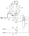
- FIG. 4 shows a configuration example of the VOC recovery device provided on the downstream side of the discharge vent 212 of the breather valve portion 2.
- the “open state” is shown in white, and the “closed state” is shown in black.
- a plurality of, for example, two adsorption towers 41a and 41b are connected in parallel to the exhaust line 401 through which the gas discharged from the storage tank 1 flows. These adsorption towers 41a and 41b are filled with an adsorbent capable of adsorbing and removing VOC contained in the gas, for example, activated carbon.
- An atmospheric discharge line 402 for discharging the gas from which VOC has been removed to the atmosphere is connected to the outlet side of each adsorption tower 41a, 41b.
- an adsorption operation is performed in the adsorption tower 41a on one side to adsorb and remove VOC in the gas discharged from the storage tank 1 and release it to the atmosphere.
- the adsorption tower 41b is disconnected from the exhaust line 401 and the atmospheric discharge line 402, and the adsorption tower 41b is vacuum-sucked to desorb the VOC from the adsorbent, thereby regenerating the adsorbent.
- a playback operation is being performed.
- the VOC adsorption operation and the adsorbent regeneration operation are alternately performed in the adsorption towers 41a and 41b.
- a desorption gas line 403 through which the VOC desorbed from the adsorbent during the regeneration operation flows is connected to the exhaust line 401. Connected in parallel.
- the desorption gas lines 403 connected to the adsorption towers 41 a and 41 b merge on the downstream side and are connected to the suction side of the common vacuum pump 43.
- an absorption tower 42 for performing an operation of absorbing and removing VOC using a solvent is provided on the discharge side of the vacuum pump 43.
- a separator that separates the lubricant discharged from the vacuum pump 43 may be provided between the vacuum pump 43 and the absorption tower 42.
- the absorption tower 42 of this example uses a petroleum product that is the liquid 31 in the storage tank 1 as a solvent for absorbing VOC.
- the absorption tower 42 is filled with a packing 421 for improving the efficiency of VOC and solvent, and the VOC discharged from the vacuum pump 43 is introduced to the lower side of the region filled with the packing 421.
- the solvent extracted from the storage tank 1 is distributed and supplied to the upper side of the above-described filling region of the filling material 421 by the solvent supply pump 44 through the solvent supply line 404.
- the VOC and the solvent come into countercurrent contact in the filling region of the filler 421, and the VOC is absorbed and removed in the solvent.
- the gas from which the VOC has been removed is extracted from the top of the absorption tower 42 and merged into the exhaust line 401, and after the VOC is further removed by adsorption in the adsorption towers 41a and 41b, it is released to the atmosphere.
- the solvent that has absorbed VOC is extracted from the bottom of the absorption tower 42 by the solvent recovery pump 45 and returned to the storage tank 1 via the solvent recovery line 405.
- emitted from the storage tank 1 is not limited to this example.
- a VOC recovery device that absorbs and removes VOC by bringing the gas discharged from the storage tank 1 into contact with a solvent may be provided, or VOC is not recovered and the VOC is burned in a flare stack and then returned to the atmosphere. May be released.
- thermal energy from the sun 501 can be cited as one of the largest factors that affect the pressure change of the gas 32 in the storage tank 1.
- the thermal energy supplied from the sun 501 can be specified by the longitude and latitude of the point where the storage tank 1 is installed and the calendar date. For example, in the northern hemisphere, the thermal energy supplied from the sun 501 is maximized on the summer solstice day of the blue sky.
- the thermal energy supplied from the sun 501 is the energy of the partition wall of the storage tank 1 irradiated with sunlight 502 as the sun 501 moves and the energy per unit area of the partition wall. It also changes over time as the density changes. Therefore, the inflow heat amount or the outflow heat amount with respect to the liquid 31 or the gas 32 through the partition wall of the storage tank 1 varies depending on the position of the partition wall, and also changes with time at each position.
- a method for estimating gas discharge according to an embodiment of the present invention is a computational fluid dynamics (CFD) model that takes into account the configuration of the storage tank 1 described above and the temperature change mechanism of the liquid 31 and gas 32 inside. Create and analyze. Based on the analysis result, the amount of gas discharged from the relief valve 211 and the amount of gas sucked from the suction valve 221 are estimated.
- CFD computational fluid dynamics
- Preconditions (a) to (e) are determined (P1: first step).
- Thermodynamic properties of the liquid 31 and gas 32 in the storage tank 1 include various physical properties required for CFD analysis, such as specific heat, vapor pressure, density, and viscosity of the liquid 31 and gas 32. Set up. When these physical properties have temperature dependence, a function or a table that expresses the correspondence between temperature and physical property values may be set. In addition, when the liquid 31 or the gas 32 includes a plurality of components, these physical properties may be set for each component, or the physical properties may be set for a mixed fluid including a plurality of components. Good. (E) for the operating pressure of the suction valve 221, in addition to the working pressure P 2 of the intake valve 221 when performing a suction of the gas has been described with reference to FIG. 3, the suction valve 221 is a valve seat described with reference to FIG. 2 The return pressure P 2 ′ when closing 224 is also set.
- initial conditions relating to the internal volume, temperature, and pressure are set for the liquid 31 and the gas 32 in the storage tank 1 (P2: second step).
- P2 second step
- the content volume of the liquid 31 in the storage tank 1 is determined, the remaining region becomes a gas phase space where the gas 32 exists, and the height position of the gas-liquid interface is specified.
- the temperature an average temperature of the liquid 31 and the gas 32 in the storage tank 1 may be set, or a temperature setting reflecting a temperature distribution grasped in advance may be performed.
- the pressure is set for the gas 32, but the pressure of the liquid 31 may be set as necessary.
- the distribution of the inflow heat amount / outflow heat amount through the partition walls (the bottom plate portion 101, the side wall portion 102, and the fixed roof portion 103) of the storage tank 1 is determined, and the temperature change of the liquid 31 and the gas 32 is determined by CFD analysis.
- the amount of mass transfer between the liquid and the gas is calculated by calculating the change in the liquid equilibrium state (P3: third step).
- the longitude and latitude of the point where the storage tank 1 is installed and the calendar day can be taken into consideration. For example, when determining the maximum processing capacity of the VOC device, in the northern hemisphere, the heat energy supplied from the sun 501 is supplied from the sun 501 at a predetermined longitude and latitude on the day of the blue sky summer solstice. Determine the thermal energy to be used.
- the irradiation region of sunlight 502 corresponding to the position of the sun 501 (the region 502 hatched with diagonal lines in the storage tank 1 shown in FIG. 5 is irradiated with sunlight 502.
- the inflow heat quantity / outflow heat quantity at each position of the partition wall of the storage tank 1 is determined.
- the inflow heat quantity / outflow heat quantity is determined in consideration of the temperature difference between the outside of the storage tank 1 and the outside air.
- the amount of inflow heat from the heating facility is also taken into consideration.
- the various settings of the first step and the second step and the determination of the inflow heat amount / outflow heat amount distribution in the third step are performed via software used for CFD analysis.
- the various settings of the first process and the second process and the determination of the distribution of the inflow heat quantity / outflow heat quantity in the third process are not strictly distinguished from each other, and according to the specifications of the CFD analysis software, etc.
- the setting items in the process may be set in parallel.
- the software used for the CFD analysis may be a commercially available general-purpose CFD analysis software, or may be dedicated CFD analysis software developed to execute the gas emission amount estimation method of this example.
- the pressure change of the gas 32 in the storage tank 1 is obtained from the mass transfer amount between the gas and the liquid, and whether or not the relief valve 211 and the suction valve 221 are operated, and the amount of gas discharged / inhaled when there is operation. Is calculated (P4: fourth step).
- VOCs contained in the discharged gas and others The ratio (VOC concentration) of the substance can be specified. As a result, the amount of VOC discharged from the relief valve 211 can be obtained.
- the internal volume of the gas 31 in the storage tank 1 ascertained from the quantity can be used as an initial condition when a new calculation is performed when the position of the sun 501 changes.
- the maximum discharge flow rate of gas per unit time and the gas discharged within a preset period for example, one day
- the VOC discharge amount can be calculated from the VOC concentration in the gas, the amount of adsorbent charged in the adsorption towers 41a and 41b by the VOC recovery device, the flow rate of the solvent supplied to the absorption tower 42, various pumps 43 , 44 and 45 (P5).
- the VOC recovery device is a solvent absorption method, it is reflected in the determination of the flow rate of the solvent, and when the VOC is burned in the flare stack, it is reflected in the determination of the flare stack size. Is possible.
- the method for estimating the gas discharge amount based on the inflow heat amount and the outflow heat amount with respect to the liquid 31 containing VOC stored in the storage tank 1, between the liquid 31 and the gas 32 in the storage tank 1. Since the mass transfer amount is specified and the gas discharge amount from the relief valve 221 is obtained based on the mass transfer amount, an accurate gas discharge amount can be grasped. As a result, it is possible to appropriately determine the capability of the VOC recovery device and the like, and it is possible to reduce an increase in device cost due to an excessive estimation of the gas discharge amount.
- the example described with reference to FIGS. 1 to 3 shows an example in which the gas discharged from the relief valve 211 is guided to the VCO recovery device via the discharge vent 212, but the breather valve unit 2 It is not indispensable to provide the discharge vent 212. Even in the case where the outlet side of the relief valve 211 is opened to the atmosphere and the gas discharged from the storage tank 1 is released to the atmosphere, it is needless to say that the gas discharge amount estimation method of this example can be applied. For example, when the storage tank 1 is installed in a place remote from an urban area, it can be used for examining whether or not it is necessary to install a VOC recovery device when the amount of VOC emission is extremely small.
Landscapes
- Engineering & Computer Science (AREA)
- Physics & Mathematics (AREA)
- Fluid Mechanics (AREA)
- General Physics & Mathematics (AREA)
- Mechanical Engineering (AREA)
- General Engineering & Computer Science (AREA)
- Filling Or Discharging Of Gas Storage Vessels (AREA)
Abstract
Description
(a)リリーフ弁を備えた固定屋根式の貯蔵タンクのタンク形状と、(b)前記リリーフ弁の作動圧力と、(c)前記貯蔵タンク内の液体の熱力学的物性と、(d)前記貯蔵タンク内の気体の熱力学的物性と、に係る前提条件を設定する第1工程と、
前記貯蔵タンク内の液体及び気体の各々について、内容量、温度、圧力の初期条件を設定する第2工程と、
前記貯蔵タンクの隔壁を介した、前記液体及び気体に対する流入熱量または流出熱量を定め、数値流体力学解析により、前記液体及び気体の温度変化と、気液平衡状態の変化とを計算して、前記液体-気体間の物質移動量を求める第3工程と、
前記物質移動量に基づいて前記気体の圧力変化を求め、変化後の気体の圧力が前記リリーフ弁の作動圧力を超えている場合には、当該リリーフ弁から排出される気体の排出量を求める第4工程と、を含むことを特徴とする。
(1)前記リリーフ弁は吐出ベントを備え、当該リリーフ弁から排出された気体は、前記吐出ベントを介して前記気体に含まれる揮発性の物質の回収装置へ向けて排出されること。
(2)前記貯蔵タンクは吸入弁を備え、前記第1工程では、前記前提条件として、さらに(e)前記吸入弁の作動圧力の設定を行うことと、前記第4工程では、前記圧力変化後の気体の圧力が前記吸入弁の作動圧力を下回っている場合には、当該吸入弁から吸入される気体の吸入量を求めること。このとき、前記吸入弁は吸入ベントを備え、当該吸入弁から吸入される気体は、前記吸入ベントを介して供給される不活性ガスであること。
(3)前記第3工程では、数値流体力学解析により、前記液体及び気体の対流に起因する熱移動を計算して、前記液体及び気体の温度変化と、気液平衡状態の変化とを特定すること。
(4)前記第3工程にて求めた前記液体及び気体の温度変化と、前記第4工程にて求めた前記気体の圧力変化と、この圧力変化より把握される貯蔵タンクの気体の内容量と、に基づき、前記第2工程の新たな初期条件を設定することと、前記第2工程の新たな初期条件を設定した後、前記液体及び気体に対する新たな流入熱量または流出熱量を定めて前記第3工程、第4工程を実行することと、前記第2工程の新たな初期条件の設定と、その後の第3工程、第4工程の実行とを繰り返すことにより、前記リリーフ弁から排出される気体の排出量の経時変化を求めること。
(5)(4)において、前記リリーフ弁から排出される気体の排出量の経時変化に基づき、単位時間当たりの最大排出流量、または予め設定した期間内に排出される気体の総排出量を求めること。
(6)前記第3工程にて定められる液体及び気体に対する流入熱量または流出熱量は、太陽光から前記隔壁を介して貯蔵タンク内に供給される熱エネルギーに基づき定められること。前記太陽光から供給される熱エネルギーは、当該貯蔵タンクが設置されている地点の経緯度と、暦日とにより定められること。
(7)前記貯蔵タンク内の気体には、前記揮発性の物質と、その他の物質とが含まれ、前記第3工程にて求めた前記液体-気体間の物質移動量と、前記第4工程にて求めた気体の排出量とに基づき、前記揮発性の物質の排出量を求めること。
図1には、円筒形状の側壁部102の上面にドームルーフ状の固定屋根部103を設けた貯蔵タンク1の例を示してある。
貯蔵タンク1には、貯蔵対象の液体の受け入れや払出しを行うための受入ライン/払出ラインの他、これらのラインに設けられる輸送ポンプ、貯蔵タンク1内の液体の撹拌を行うためのタンクミキサー、貯蔵タンク1に貯蔵される液体の性状や貯蔵タンク1の設置地域の気候などに応じて設けられる保温設備や加熱設備など、適宜、種々の付帯設備が設けられている。図1においては、これらの付帯設備の記載は省略してある。
本例では、揮発性の物質としてベンゼンやトルエンといった揮発性有機物(以下、「VOC」ともいう)を含む石油製品である液体31を貯蔵した貯蔵タンク1の例について説明する。
リリーフ弁211の出口側は、排気ライン401を介して後述のVOC回収装置に接続されている。また、吸入弁221の入口側は、貯蔵タンク1内にシール用の不活性ガスである例えば窒素ガスを供給するための窒素ガス供給ライン104に接続されている。
なお、吸入弁221から吸入される気体は不活性ガスに限定されない。例えば、貯蔵タンク1が気体シールの必要のない液体31を貯蔵している場合には、吸入弁221を開放して大気を吸入してもよい。
気体の排出により貯蔵タンク1内の圧力が低下して、リリーフ弁211の復帰圧力P1’以下になると、バネ215によってリリーフ弁211が押し下げられ、弁座214が閉じられる。
窒素ガスの吸入により貯蔵タンク1内の圧力が上昇して、吸入弁221の復帰圧力P2’以上になると、自重によりリリーフ弁211が降下し、弁座224が閉じられる。
また、吸入弁221は、図2、3のようにリリーフ弁221と隣接させて一つのブリーザー弁部2とする場合もあるが、吸入弁221とリリーフ弁221をそれぞれ独立させて設ける場合もある。
貯蔵タンク1から排出された気体が流れる排気ライン401に対しては、複数基、例えば2基の吸着塔41a、41bが並列に接続されている。これらの吸着塔41a、41bには、気体中に含まれるVOCを吸着除去可能な吸着剤、例えば活性炭が充填されている。各吸着塔41a、41bの出口側には、VOCが除去された気体を大気へ放出するための大気放出ライン402が接続されている。
本例のVOC回収装置においては、吸着塔41a、41bにおいて、VOCの吸着操作と吸着剤の再生操作とが交互に行われる。
VOCが除去された気体は、吸収塔42の塔頂から抜き出され、排気ライン401に合流した後、吸着塔41a、41bにてさらにVOCの吸着除去が行われてから大気へ放出される。また、VOCを吸収した溶剤は、溶剤回収ポンプ45により吸収塔42の塔底から抜き出され、溶剤回収ライン405を介して貯蔵タンク1へ戻される。
さらに、液体31や気体32においては、内部の温度差に伴う対流が発生し(図1)、対流に伴う熱移動や物質移動により、VOCの揮発や凝縮を支配する気体-液体の界面の温度や気体中のVOC濃度に影響を及ぼす。
これら種々の要因の中で、貯蔵タンク1の気体32の圧力変化に影響を与える最も大きな要因の一つとして、太陽501からの熱エネルギーの供給が挙げられる。太陽501から供給される熱エネルギーは、貯蔵タンク1が設置されている地点の経緯度と、暦日とにより特定することができる。例えば北半球の場合、青天の夏至の日において、太陽501から供給される熱エネルギーが最大となる。
従って、貯蔵タンク1の隔壁を介した液体31や気体32に対する流入熱量または流出熱量は、隔壁の位置に応じて異なり、さらに各位置においても経時的に変化することになる。
以下、図7を参照しながら上記推定を行う手順について説明する。
(b)リリーフ弁211の作動圧力については、図2を用いて説明した気体の排出を行う際のリリーフ弁211の作動圧力P1に加え、図3を用いて説明したリリーフ弁211が弁座214を閉じる際の復帰圧力P1’の設定も行う。
(e)吸入弁221の作動圧力については、図3を用いて説明した気体の吸入を行う際の吸入弁221の作動圧力P2に加え、図2を用いて説明した吸入弁221が弁座224を閉じる際の復帰圧力P2’の設定も行う。
貯蔵タンク1内における液体31の内容量を決定すると、残る領域は気体32が存在する気相空間となり、気体-液体の界面の高さ位置が特定される。温度は、貯蔵タンク1内の液体31、気体32の平均温度を設定してもよいし、予め把握している温度分布を反映した温度設定を行ってもよい。また、通常、圧力設定は、気体32について行うが、必要に応じて液体31の圧力設定を行ってもよい。
また既述のように、貯蔵タンク1が加熱設備を備える場合には、加熱設備からの流入熱量も考慮する。
上述の第2~第4工程を繰り返すことにより、リリーフ弁211から排出される気体の排出量の経時変化を求めることができる。
ここで、CFD解析ソフトウェアが、流入熱量/流出熱量の変化を考慮した動的解析を行うことができる場合には、既述の第2~第4工程を繰り返して実行する手法に替えて、CFDの動的解析によりリリーフ弁211から排出される気体の排出量の経時変化を求めてもよいことは勿論である。
また、既述のように、VOC回収装置が溶剤吸収方式である場合には、溶剤の流量の決定、フレアスタックにてVOCを燃焼させる場合には、フレアスタックのサイズの決定などに反映することが可能である。
この結果、VOC回収装置などの能力を適正に決定することが可能となり、気体排出量の過大な見積もりに伴う装置コストの増大を低減することができる。
2 ブリーザー弁部
211 リリーフ弁
212 吐出ベント
221 吸入弁
222 吸入ベント
32 気体
31 液体
41a、41b
吸着塔
42 吸収塔
501 太陽
Claims (10)
- 揮発性の物質を含む液体を貯蔵した貯蔵タンクからの気体排出量の推定方法であって、
(a)リリーフ弁を備えた固定屋根式の貯蔵タンクのタンク形状と、(b)前記リリーフ弁の作動圧力と、(c)前記貯蔵タンク内の液体の熱力学的物性と、(d)前記貯蔵タンク内の気体の熱力学的物性と、に係る前提条件を設定する第1工程と、
前記貯蔵タンク内の液体及び気体の各々について、内容量、温度、圧力の初期条件を設定する第2工程と、
前記貯蔵タンクの隔壁を介した、前記液体及び気体に対する流入熱量または流出熱量を定め、数値流体力学解析により、前記液体及び気体の温度変化と、気液平衡状態の変化とを計算して、前記液体-気体間の物質移動量を求める第3工程と、
前記物質移動量に基づいて前記気体の圧力変化を求め、変化後の気体の圧力が前記リリーフ弁の作動圧力を超えている場合には、当該リリーフ弁から排出される気体の排出量を求める第4工程と、を含むことを特徴とする気体排出量の推定方法。 - 前記リリーフ弁は吐出ベントを備え、当該リリーフ弁から排出された気体は、前記吐出ベントを介して前記気体に含まれる揮発性の物質の回収装置へ向けて排出されることを特徴とする請求項1に記載の気体排出量の推定方法。
- 前記貯蔵タンクは吸入弁を備え、
前記第1工程では、前記前提条件として、さらに(e)前記吸入弁の作動圧力の設定を行うことと、
前記第4工程では、前記圧力変化後の気体の圧力が前記吸入弁の作動圧力を下回っている場合には、当該吸入弁から吸入される気体の吸入量を求めることと、を特徴とする請求項1に記載の気体排出量の推定方法。 - 前記吸入弁は吸入ベントを備え、当該吸入弁から吸入される気体は、前記吸入ベントを介して供給される不活性ガスであることを特徴とする請求項3に記載の気体排出量の推定方法。
- 前記第3工程では、数値流体力学解析により、前記液体及び気体の対流に起因する熱移動を計算して、前記液体及び気体の温度変化と、気液平衡状態の変化とを特定することを特徴とする請求項1に記載の気体排出量の推定方法。
- 前記第3工程にて求めた前記液体及び気体の温度変化と、前記第4工程にて求めた前記気体の圧力変化と、この圧力変化より把握される貯蔵タンクの気体の内容量と、に基づき、前記第2工程の新たな初期条件を設定することと、
前記第2工程の新たな初期条件を設定した後、前記液体及び気体に対する新たな流入熱量または流出熱量を定めて前記第3工程、第4工程を実行することと、
前記第2工程の新たな初期条件の設定と、その後の第3工程、第4工程の実行とを繰り返すことにより、前記リリーフ弁から排出される気体の排出量の経時変化を求めることと、を特徴とする請求項1に記載の気体排出量の推定方法。 - 前記リリーフ弁から排出される気体の排出量の経時変化に基づき、単位時間当たりの最大排出流量、または予め設定した期間内に排出される気体の総排出量を求めることを特徴とする請求項6に記載の気体排出量の推定方法。
- 前記第3工程にて定められる液体及び気体に対する流入熱量または流出熱量は、太陽光から前記隔壁を介して貯蔵タンク内に供給される熱エネルギーに基づき定められることを特徴とする請求項1に記載の気体排出量の推定方法。
- 前記太陽光から供給される熱エネルギーは、当該貯蔵タンクが設置されている地点の経緯度と、暦日とにより定められることを特徴とする請求項8に記載の気体排出量の推定方法。
- 前記貯蔵タンク内の気体には、前記揮発性の物質と、その他の物質とが含まれ、前記第3工程にて求めた前記液体-気体間の物質移動量と、前記第4工程にて求めた気体の排出量とに基づき、前記揮発性の物質の排出量を求めることを特徴とする請求項1に記載の気体排出量の推定方法。
Priority Applications (5)
| Application Number | Priority Date | Filing Date | Title |
|---|---|---|---|
| PCT/JP2016/056799 WO2017149760A1 (ja) | 2016-03-04 | 2016-03-04 | 気体排出量の推定方法 |
| JP2016541700A JP6019271B1 (ja) | 2016-03-04 | 2016-03-04 | 気体排出量の推定方法 |
| US16/065,130 US10309819B2 (en) | 2016-03-04 | 2016-03-04 | Method of estimating gas emission amount |
| CN201680067147.XA CN108369122B (zh) | 2016-03-04 | 2016-03-04 | 气体排出量的推断方法 |
| KR1020187011900A KR101912208B1 (ko) | 2016-03-04 | 2016-03-04 | 기체 배출량의 추정 방법 |
Applications Claiming Priority (1)
| Application Number | Priority Date | Filing Date | Title |
|---|---|---|---|
| PCT/JP2016/056799 WO2017149760A1 (ja) | 2016-03-04 | 2016-03-04 | 気体排出量の推定方法 |
Publications (1)
| Publication Number | Publication Date |
|---|---|
| WO2017149760A1 true WO2017149760A1 (ja) | 2017-09-08 |
Family
ID=57216885
Family Applications (1)
| Application Number | Title | Priority Date | Filing Date |
|---|---|---|---|
| PCT/JP2016/056799 Ceased WO2017149760A1 (ja) | 2016-03-04 | 2016-03-04 | 気体排出量の推定方法 |
Country Status (5)
| Country | Link |
|---|---|
| US (1) | US10309819B2 (ja) |
| JP (1) | JP6019271B1 (ja) |
| KR (1) | KR101912208B1 (ja) |
| CN (1) | CN108369122B (ja) |
| WO (1) | WO2017149760A1 (ja) |
Cited By (1)
| Publication number | Priority date | Publication date | Assignee | Title |
|---|---|---|---|---|
| KR20220150923A (ko) * | 2020-03-26 | 2022-11-11 | 삼성중공업 주식회사 | 액화가스 저장탱크 시스템, 그 설계 및 제조 방법 |
Families Citing this family (1)
| Publication number | Priority date | Publication date | Assignee | Title |
|---|---|---|---|---|
| CN117054602A (zh) * | 2023-08-01 | 2023-11-14 | 中石化石油工程技术服务股份有限公司 | 一种VOCs监测方法 |
Citations (1)
| Publication number | Priority date | Publication date | Assignee | Title |
|---|---|---|---|---|
| JP2015175488A (ja) * | 2014-03-17 | 2015-10-05 | 大阪瓦斯株式会社 | 圧縮機稼働計画策定システム |
Family Cites Families (11)
| Publication number | Priority date | Publication date | Assignee | Title |
|---|---|---|---|---|
| US4976162A (en) * | 1987-09-03 | 1990-12-11 | Kamen Dean L | Enhanced pressure measurement flow control system |
| US4959569A (en) * | 1989-11-22 | 1990-09-25 | Westinghouse Electric Corp. | Stator coil water system early alert hydrogen leakage monitor |
| JP2691046B2 (ja) | 1990-05-02 | 1997-12-17 | 本田技研工業株式会社 | ブローチ加工方法 |
| JPH0413513U (ja) | 1990-05-21 | 1992-02-04 | ||
| JP4235429B2 (ja) * | 2002-10-17 | 2009-03-11 | キヤノン株式会社 | 密封容器のガス測定方法、並びに密封容器及び画像表示装置の製造方法 |
| DE112004000270T5 (de) * | 2003-02-10 | 2006-10-19 | Sheldon, Michael L., Georgetown | Messung von Fluidvolumina in einem Behälter unter Verwendung von Druck |
| US9396162B2 (en) * | 2010-07-22 | 2016-07-19 | John APPLEYARD | Method and apparatus for estimating the state of a system |
| CN202983499U (zh) * | 2012-11-29 | 2013-06-12 | 华南理工大学 | 一种基于cfd的工业锅炉sncr脱硝装置 |
| JP6486376B2 (ja) * | 2013-10-10 | 2019-03-20 | インジェヴィティ・サウス・カロライナ・エルエルシー | 蒸発燃料蒸気のエミッション制御システム |
| CN204017667U (zh) * | 2014-01-13 | 2014-12-17 | 广东清华中邦热能科技有限公司 | 一种新型scr脱硝系统 |
| CN103983313A (zh) * | 2014-05-30 | 2014-08-13 | 重庆长厦安基建筑设计有限公司 | 一种管网阻力系数确定方法及管网风量测量方法 |
-
2016
- 2016-03-04 US US16/065,130 patent/US10309819B2/en active Active
- 2016-03-04 JP JP2016541700A patent/JP6019271B1/ja active Active
- 2016-03-04 KR KR1020187011900A patent/KR101912208B1/ko active Active
- 2016-03-04 CN CN201680067147.XA patent/CN108369122B/zh active Active
- 2016-03-04 WO PCT/JP2016/056799 patent/WO2017149760A1/ja not_active Ceased
Patent Citations (1)
| Publication number | Priority date | Publication date | Assignee | Title |
|---|---|---|---|---|
| JP2015175488A (ja) * | 2014-03-17 | 2015-10-05 | 大阪瓦斯株式会社 | 圧縮機稼働計画策定システム |
Cited By (4)
| Publication number | Priority date | Publication date | Assignee | Title |
|---|---|---|---|---|
| KR20220150923A (ko) * | 2020-03-26 | 2022-11-11 | 삼성중공업 주식회사 | 액화가스 저장탱크 시스템, 그 설계 및 제조 방법 |
| JP2023525448A (ja) * | 2020-03-26 | 2023-06-16 | サムスン ヘビー インダストリーズ カンパニー リミテッド | 液化ガス貯蔵タンクシステム、その設計及び製造方法 |
| JP7494314B2 (ja) | 2020-03-26 | 2024-06-03 | サムスン ヘビー インダストリーズ カンパニー リミテッド | 液化ガス貯蔵タンクシステム、その設計及び製造方法 |
| KR102763392B1 (ko) * | 2020-03-26 | 2025-02-07 | 삼성중공업(주) | 액화가스 저장탱크 시스템, 그 설계 및 제조 방법 |
Also Published As
| Publication number | Publication date |
|---|---|
| US20190017858A1 (en) | 2019-01-17 |
| KR20180049170A (ko) | 2018-05-10 |
| US10309819B2 (en) | 2019-06-04 |
| JP6019271B1 (ja) | 2016-11-02 |
| JPWO2017149760A1 (ja) | 2018-03-15 |
| KR101912208B1 (ko) | 2018-10-26 |
| CN108369122A (zh) | 2018-08-03 |
| CN108369122B (zh) | 2019-06-18 |
Similar Documents
| Publication | Publication Date | Title |
|---|---|---|
| CN102166463B (zh) | 挥发性有机气体回收模拟试验装置 | |
| CN204294073U (zh) | 一种VOCs挥发气回收利用装置 | |
| CN204107268U (zh) | 油气回收装置 | |
| CN202279687U (zh) | 一种油气回收装置 | |
| JP6019271B1 (ja) | 気体排出量の推定方法 | |
| US8580020B2 (en) | Tank with containment chamber and gas scrubber | |
| CN108467743B (zh) | 一种油气回收凝液收集与输送装置及其方法 | |
| US9447782B2 (en) | Compressor and method for compressing technical gases | |
| CN207001381U (zh) | 一种氮气密封储罐的自主呼吸零排放系统 | |
| CN1994858A (zh) | 加油站油气回收的方法及装置 | |
| CN203874640U (zh) | 一种芳香烃类混合气体回收装置 | |
| CN201454139U (zh) | 油气回收处理装置 | |
| CN102314556A (zh) | 一种油气回收的评价方法及系统 | |
| CN105217559B (zh) | 加油站二次油气回收效率测试装置和测试方法 | |
| CN103523417A (zh) | 储油罐呼吸气回收系统 | |
| JP4658888B2 (ja) | ベーパー回収装置及びベーパー回収方法 | |
| CN201735205U (zh) | 一种分层吸附的油气回收装置 | |
| CN206837787U (zh) | 油气回收系统 | |
| CN204113773U (zh) | 一种油气运输车用动力转向油罐 | |
| CN101462689A (zh) | 加油站吸收冷凝吸附变频油气回收法 | |
| CN104923040B (zh) | 膜法油气回收分组控制装置及其使用方法 | |
| CN107413168A (zh) | 油气回收系统及其控制方法 | |
| CN108692184A (zh) | 压缩储气法自动控制挥发性化工产品气体回收技术 | |
| CN205269393U (zh) | 基于化学吸附的气相脱汞一体化装置 | |
| CN208865218U (zh) | 一种节能环保式油气回收处理装置 |
Legal Events
| Date | Code | Title | Description |
|---|---|---|---|
| ENP | Entry into the national phase |
Ref document number: 2016541700 Country of ref document: JP Kind code of ref document: A |
|
| ENP | Entry into the national phase |
Ref document number: 20187011900 Country of ref document: KR Kind code of ref document: A |
|
| NENP | Non-entry into the national phase |
Ref country code: DE |
|
| 121 | Ep: the epo has been informed by wipo that ep was designated in this application |
Ref document number: 16892600 Country of ref document: EP Kind code of ref document: A1 |
|
| 122 | Ep: pct application non-entry in european phase |
Ref document number: 16892600 Country of ref document: EP Kind code of ref document: A1 |