WO2017149730A1 - エレベータ駆動機用連結装置 - Google Patents
エレベータ駆動機用連結装置 Download PDFInfo
- Publication number
- WO2017149730A1 WO2017149730A1 PCT/JP2016/056637 JP2016056637W WO2017149730A1 WO 2017149730 A1 WO2017149730 A1 WO 2017149730A1 JP 2016056637 W JP2016056637 W JP 2016056637W WO 2017149730 A1 WO2017149730 A1 WO 2017149730A1
- Authority
- WO
- WIPO (PCT)
- Prior art keywords
- elevator
- car
- rescue
- rotating body
- connecting member
- Prior art date
Links
Images


Classifications
-
- B—PERFORMING OPERATIONS; TRANSPORTING
- B66—HOISTING; LIFTING; HAULING
- B66B—ELEVATORS; ESCALATORS OR MOVING WALKWAYS
- B66B5/00—Applications of checking, fault-correcting, or safety devices in elevators
-
- B—PERFORMING OPERATIONS; TRANSPORTING
- B66—HOISTING; LIFTING; HAULING
- B66B—ELEVATORS; ESCALATORS OR MOVING WALKWAYS
- B66B11/00—Main component parts of lifts in, or associated with, buildings or other structures
- B66B11/04—Driving gear ; Details thereof, e.g. seals
Definitions
- This invention relates to a connecting device for an elevator driving machine that moves a car by using an elevator provided by connecting two driving machines using a connecting member at the time of a power failure or the like.
- the conventional large-capacity elevator rescue methods include a method of using a battery in the event of a power failure, and a method of moving a car using gravity by opening a braking device of a driving machine.
- the control panel or the drive unit is operated via a control unit instead of the control panel by supplying power from the battery, and the car arranged in the drive unit is moved up and down via a hoisting rope.
- Patent Document 2 discloses a conventional technique for gradually lowering a car by using gravity by causing a braking device to repeatedly open and brake.
- the present invention has been made to solve such a problem, and does not require power supply, and when the car and the counterweight are in a balanced state, the car is raised and lowered to rescue passengers in the car. Objective.
- the connecting device for an elevator driving machine is connected to the shaft end of the rotating body of at least two elevator driving machines provided with a rotating body that lifts and lowers the weight of the car and the counterweight via a hoisting rope.
- a member is provided.
- another connecting device for an elevator drive according to the present invention is connected to a motor for driving at least two elevator drives each provided with a rotating body that lifts and lowers a weight with a car via a hoisting rope.
- the connecting member is provided.
- the car can be raised and lowered without supplying power even in a balanced state where the car does not move up and down even when the braking device is opened.
- FIG. 3 is an enlarged view of a portion A in FIG. 2. It is a top view connected with the drive machine of the two elevator apparatuses in Embodiment 2 which concerns on this invention through a connection apparatus. It is an enlarged view which shows the coupling device in Embodiment 2 which concerns on this invention. It is a top view which installs the normal time coupling device in Embodiment 3 which concerns on this invention.
- Embodiment 3 It is a block diagram of the two elevator apparatuses at the normal time in Embodiment 3 which concerns on this invention. It is a top view connected with the drive device of the two elevator apparatuses at the time of abnormality (or rescue time) in Embodiment 3 which concerns on this invention via a connection device. It is a figure connected with the drive machine of the two elevator apparatuses in Embodiment 4 which concerns on this invention via a connection apparatus.
- Embodiment 1 of the present invention will be described below.
- the present invention is not limited to the first embodiment.
- at least two elevator apparatuses are connected via a connecting member, and the other elevator apparatus is rotated by rotating the rotating body of the drive device of the other elevator apparatus by imbalance of the other elevator apparatus. Raise and lower the basket.
- Embodiment 1 will be described with reference to FIG. 1, FIG. 2, and FIG.
- FIG. 1 is a diagram showing a configuration in which two elevator apparatuses are connected via a connecting apparatus according to the present invention.
- Two elevator apparatuses are provided side by side, and the rotating shafts of the rotating bodies of the two drive machines are coaxial.
- the driving machine 1a is a driving machine that is installed in a hoistway (not shown) and moves the car 2a up and down.
- the car 2a is used by passengers.
- the counterweight 3a is provided at a position facing the car 2a in order to balance the weight of the car 2a.
- the hoisting rope 4a suspends and supports the counterweight 2a and the counterweight 3a, and guides the lifting and lowering of the counterweight 2a and the counterweight 3a by driving of the driving machine 1a.
- the baffle wheel 5a is disposed below the driving machine 1a and used in an auxiliary manner in order to keep the distance between the car 2a and the counterweight 3a constant.
- the connecting member 6 connects two elevator apparatuses.
- the rotating body of the driving machine 1a is rotated by supplying electric power, and the rotating body of the driving machine 1a moves up and down the counterweight 3a with the car 2a via the hoisting rope 4a.
- rotation of the drive machine 1a is stopped by a brake apparatus (not shown) installed in the drive machine 1a, and raising / lowering of the car 2a and the counterweight 3a is stopped.
- the drive machine 1a cannot be rotated by power supply, and the drive machine 1a cannot lift and lower the counterweight 3a with the car 2a by electric power.
- the car in the case of a power failure and in a balanced state with a car and a counterweight, the car can be lifted and lowered to rescue passengers in the car without supplying power by the battery.
- FIG. 2 is a diagram in which two elevator apparatuses are installed in the side, and a driving machine is connected through a connecting apparatus.
- the braking device 9a is a braking device that brakes the rotation of the drive machine 1a.
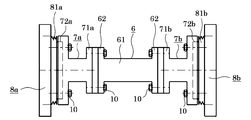
- FIG. 3 is an enlarged view of A in FIG. In FIG. 3, the structure and installation of the connecting member 6 installed at the shaft end of the drive machine 1a of one of the two elevator apparatuses will be described.
- the connecting member 6 includes a connecting shaft 61 that is an intermediate portion, and connecting flange portions (connecting fixing portions) 62 provided at both ends of the connecting shaft 61.
- the connecting shaft 61 has a cylindrical shape.
- the connection flange portion 62 is a protrusion that protrudes around the connection shaft 61.
- the shapes of the connecting shaft 61 and the connecting flange portion 62 are not limited.
- the spacer 7a is disposed between the connecting flange portion 62 of the connecting member 6 and the driving machine 1a.
- the spacer 7a is inserted into the joint of parts in order to adjust the interval appropriately.
- the spacer 7a has a cylindrical shape, but is not limited to a cylindrical shape.
- a spacer flange portion 71 a for joining to the connection flange portion 62 of the connection member 6 is provided on one side of the spacer 7 a.
- the spacer flange portion 71 a is fixed via the connecting flange portion 62 and the bolt 10.
- a recess 72a for fixing to the rotating body 8a of the driving machine 1a is provided.
- Rotating shaft fixing portion 81a is provided at the shaft end of rotating body 8a.
- the rotating shaft fixing portion 81a is a stepped convex portion 81a.
- a stepped convex portion 81 a is fitted into the concave portion 72 a of the spacer 7 a and is fixed via the bolt 10.
- a convex portion may be provided on the spacer 7a side, and a concave portion may be provided at the shaft end portion of the rotating body 8a.
- the shape of the recessed part 72a and the convex part 81a is not limited, What is necessary is just to be able to fix the spacer 7a and the rotating shaft 8a.
- FIG. 1 the rescue operation using the connecting device in the first embodiment will be described with reference to FIGS. 1, 2, and 3.
- FIG. 1
- the elevator device a is the rescued side
- the elevator device b is the rescue side.
- the rescue of the car 2a when the drive machine 1a and a control device (not shown) are stopped in the case of a power failure and in a state where the balance between the car 2a and the counterweight 3a is achieved will be described.
- the cover of the drive machine 1a (rescued side) of the elevator apparatus a is removed, and the convex portion 81a at the shaft end of the rotating body 8a is exposed.
- the projection 81a at the end of the shaft is fitted into the recess 72a of the spacer 7a and fixed via the bolt 10.
- the drive unit 1b (rescue side) of the side elevator b also removes the cover, exposes the convex part 81b of the shaft end of the rotating body 8b, fits the convex part 81b into the concave part 72b, and fixes it via the bolt 10.
- the connecting member 6 is disposed between the spacer 7a and the spacer 7b. The connecting member 6 and the spacer 7a, and the connecting member 6 and the spacer 7b are fixed with bolts 10, respectively.
- the rotary shaft 8a of the rescue-side drive machine 1a is connected to the rotary shaft 8b of the rescue-side drive machine 1b.
- the braking devices 9a and 9b of the two driving machines 1a and 1b are simultaneously opened.
- the rotating body 8a of the rescue-side driving machine 1a is rotated through the connecting member 6 by imbalance between the car 2b and the counterweight 3b in the side-by-side elevator apparatus b, and the rotating body 8a rotates to rotate the rotating apparatus 8a.
- the car 2a can be raised and lowered. Further, the car 2a can be moved to the rescue floor by repeating the braking operation and the releasing operation of the braking device 9a.
- the car 2a on the rescue side can be rescued via the connecting member 6 due to the imbalance of the elevator device b.
- the car 2a on the rescue side and the counterweight 3a have a small unbalance and the car 2a cannot be lifted or lowered even when the braking device 9a is opened.
- the rotating body 8a of the driving machine 1a and the rotating body 8b of the driving machine 1b are connected by the connecting member 6 to use the unbalance between the rescue-side car 2b and the counterweight 3b.
- the car 2a on the rescue side can be raised and lowered to the rescue floor.
- the car can be rescued in the event of a power outage, in a state where the balance between the car and the counterweight is balanced, or in the event of an abnormality such as damage to the rescue side drive or control device. it can.
- FIG. 1 a second embodiment of the present invention will be described with reference to FIGS. 1, 4, and 5.
- FIG. Constituent elements common to the first embodiment are denoted by the same reference numerals and description thereof is omitted.
- the rescue is performed via the connecting member 6.
- driving of the two elevator apparatuses is performed. Even if the rotational axes of the body rotating bodies 8a and 8b are not coaxial, the same effect as in the first embodiment can be obtained.
- FIG. 4 is a diagram in which the rotating bodies 8a and 8b of the driving machine are connected via the connecting device 6 when the rotating shafts of the rotating bodies 8a and 8b of the two driving machines in the second embodiment are not coaxial. is there.
- the spacer 7a is provided with a recess 72a and a spacer fixing portion (not shown) for fixing to the connecting member 6, and the spacer 7b is disposed to face the spacer 7a, and is fixed to the recess 72b and the connecting member 6 (spacer fixing portion (not shown)). (Not shown).
- FIG. 5 is an enlarged view of the connecting member 6 of FIG.
- the connecting member 6 is a member that can expand and contract according to the distance between at least two rotating bodies.
- the connecting member 6 according to the second embodiment can be adjusted in length by the distance between the rotating shafts of the drive units of the two elevator apparatuses, and is a columnar expansion / contraction member.
- the connecting member 6 has a columnar connecting shaft A63 and a hollow columnar connecting shaft B64.
- the diameter of the connecting shaft A63 is smaller than the diameter of the connecting shaft B64.
- a plurality of holes 65 are provided in each of the connecting shaft A63 and the connecting shaft B64. In the second embodiment, the diameters of the holes 65 are the same, and the distances between the two holes 65 are equally spaced.
- the connecting shaft A63 and the connecting shaft B64 may be fixed without defining the diameters of the plurality of holes 65 provided in the connecting shaft A63 and the connecting shaft B64 and the distance between the two holes 65. Furthermore, universal joints 67 are provided at both ends of the connecting member 6. The universal joint 67 is fixed to the spacer fixing portion of the spacer 7 with a bolt. The universal joint 67 can freely change the angle at which the two rotating axes intersect within a certain range.
- the connecting shaft A63 is inserted into the hollow portion of the connecting shaft B64, and the connecting shaft A63 is engaged with the connecting shaft B64. After that, the position of the hole 65 provided in the connecting shaft A63 and the position of the hole 65 provided in the connecting shaft B64 are aligned from the cylindrical side surface, and the pin 66 is inserted into the two aligned holes 65 to be connected to the connecting shaft A63.
- the axis B64 is fixed.
- the total length of the connecting shaft A63 and the connecting shaft B64 is changed by shifting the connecting shaft A63 and the connecting shaft B64 and changing the hole 65 corresponding to the connecting shaft A63 and the connecting shaft B64. Thereby, it can connect even if the distance between the rotary bodies of the drive machine of two elevator apparatuses differs.
- the connecting member 6 of the second embodiment is a columnar expansion / contraction member whose length can be adjusted.
- the shape of the connecting member 6 is not limited, and there may be a corner, and it is only necessary to connect the rotating bodies of the driving machine.
- the rescue operation of the second embodiment is the same as that of the first embodiment.
- the rescue-side car 2a If the unbalance with the counterweight 3a is small and the car 2a cannot be raised or lowered even when the braking device 9a is released, or if the counterweight 2a and the counterweight 3a are in balance, the counterweight 2b is balanced. Using the unbalance with the weight 3b, the rescued car 2a can be lifted and lowered.
- the second embodiment can obtain the same effect as the first embodiment. Moreover, in Embodiment 2, it can rescue even if the rotating shaft of the rotary body of two drive machines is not coaxial.
- FIG. 3 The third embodiment of the present invention will be described below with reference to FIGS. 6, 7, and 8.
- FIG. Constituent elements common to the first embodiment are denoted by the same reference numerals and description thereof is omitted.
- the rotating body of the rotating shaft 8 is physically connected by the connecting member 6, whereas in the third embodiment, the motor 11b for driving the rescue-side driving machine 1b and the target are connected. It is the structure which connects the motor 11a which drives the rescue side drive machine 1a with a connection member.
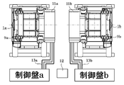
- FIG. 6 is a diagram in which the drive machines 1a and 1b of the two elevator apparatuses according to the third embodiment are installed at a normal time.
- the motor 11a and the control panel a for driving the drive machine 1a and the motor 11b and the control panel b for driving the drive machine 1b are connected to each other via power wires 13a and 13b, respectively.
- the terminal block 12 is provided between the control panel a and the control panel b.
- the terminal block 12 is a connecting member.
- FIG. 7 is a configuration diagram in which two elevator apparatuses are installed in a normal state.
- FIG. 8 is a diagram in which the drive units 1a and 1b of the two elevator apparatuses according to the third embodiment are connected by the terminal block 12 at the time of abnormality (at the time of rescue).
- the motor 11a that drives the drive machine 1a and the terminal block 12 are connected via a power wire 13a
- the motor 11b that drives the drive machine 1b and the terminal block 12 are connected via a power wire 13b. .
- the car 2a is the rescued side and the car 2b is the rescue side, as in the first and second embodiments.
- the power wire 13a from the motor 11a of the driving machine 1a for raising and lowering the car 2a to the control panel a is removed from the control panel a and attached to the terminal block 12.
- the power cable 13b from the motor 11b of the drive unit 1b to the control panel b is removed from the control panel b and attached to the terminal block 12.
- the two braking devices 9a and 9b are simultaneously opened, and the rotating body of the side-mounted driving machine 1b having an unbalance rotates.
- An electromotive force is generated in the motor 11b by the rotation of the rotating body of the driving machine 1b, and the electromotive force is supplied to the motor 11a of the driving machine 1a that moves the car 1a up and down through the power wire 13b, the terminal block 12, and the power wire 13a. .
- the motor 11a can rotate the rotary body of the drive machine 1a, and can raise / lower the cage
- the motors 11a and 11b of the two driving machines 1a and 1b are connected by the terminal block 12 so that the unbalance between the rescue-side car 2a and the counterweight 3a is small, and When the car 2a cannot be raised or lowered even when the braking device 9a is opened, an electromotive force is generated in the rescue-side motor 11b by unbalance between the rescue-side car 2b and the counterweight 3b. Then, the rescue-side motor 11a rotates the rotating body of the driving machine 1a to raise and lower the car 2a. Thereby, the car 2a can be rescued at the time of a power failure, in the case of a balance between the car 2a and the counterweight 3a, and in the case of an abnormality such as a damaged drive device or control device on the rescue side.
- Embodiment 4 FIG.
- the fourth embodiment of the present invention will be described below with reference to FIGS. Constituent elements common to the third embodiment are denoted by the same reference numerals and description thereof is omitted.
- the connecting member is always arranged with respect to the structure in which the connecting member is attached at the time of rescue of the third embodiment.
- FIG. 9 is a diagram in which the drive units of the two elevator apparatuses according to the fourth embodiment are connected by a connecting member.
- the wiring 14 is installed between the power wires 13a and 13b, and the connecting members 15 are arranged between the power wires 13a and 13b and the wire 14, respectively.
- the connecting member 15 is the changeover switch 15 and is not limited to this.
- the changeover switch 15 switches between normal and abnormal (or rescue). In normal times, the motor 11a and the control panel a are connected by a power cable 13a, and the motor 11b and the control panel b are connected by a power cable 13b. At the time of rescue, the changeover switch 15 is switched to the rescue side so that the motor 11a and the control panel a are not connected, the motor 11b and the control panel b are not connected, and the motor 11a and the motor 11b are connected to the wiring 14 and the changeover switch. 15 are connected.
- the changeover switch 15 can be installed either automatically or manually.
- the car 2a is the rescue side and the car 2b is the rescue side, as in the first to third embodiments.
- the changeover switch 15 is switched to the rescue side.
- the two braking devices 9a and 9b are simultaneously opened, and a rotating body (not shown) of the side-mounted driving machine 1b having an unbalance rotates.
- An electromotive force is generated in the motor 11b by the rotation of the rotating body, and the electromotive force is supplied to the motor 11a that moves the car 1a up and down through the changeover switch 15b, the wiring 14, and the changeover switch 15a.
- the motor 11a can rotate the rotary body of the drive machine 1a, and can raise / lower the cage
- Embodiment 4 can be rescued more easily than Embodiment 3 because no mounting work is required. Further, the same effect as in the third embodiment can be obtained.
- Embodiment 1 any embodiment from the above-described Embodiment 1 to Embodiment 4 may be combined.
Landscapes
- Engineering & Computer Science (AREA)
- Civil Engineering (AREA)
- Mechanical Engineering (AREA)
- Structural Engineering (AREA)
- Maintenance And Inspection Apparatuses For Elevators (AREA)
Abstract
この発明は、停電時等に、連結部材を用いて2つの駆動機を連結し、電力供給を必要とせず、かごと釣合いおもりとがバランス状態である場合、かごを昇降させ、かご内の乗客を救出することを目的とする。 この発明にかかるエレベータ駆動機用連結装置は、少なくとも2台のエレベータ駆動機の回転体の軸端部に連結される連結部材を備えるものである。また、少なくとも2台のエレベータ駆動機をそれぞれ駆動するモータに連結される連結部材を備えるものである。
Description
この発明は、停電時等に、連結部材を用いて2つの駆動機を連結することにより併設するエレベータを利用し、かごを移動させるエレベータ駆動機用連結装置に関するものである。
従来の大容量エレベータの救出方法は、停電時にバッテリーを使用する方法、及び駆動機の制動装置の開放動作により重力を利用してかごを移動させる方法がある。バッテリーを使用する方法では、バッテリーからの電力供給により制御盤もくしは制御盤に代わるコントロールユニットを介して駆動機を稼動させ、巻上ロープを介して駆動機に配置されたかごを昇降させることが従来技術として特許文献1に開示されている。
また、駆動機の制動装置の開放動作により重力を利用してかごを移動させる方法では、巻胴式の綱車と制動装置を有した駆動機が昇降路の下部に配置され、綱車に巻き付けられたロープはプーリーを介して昇降路の頂部に設置した一端をかごに連結されている。制動装置に開放と制動の動作を繰り返させることにより、重力を利用してかごを序々に降下させることが従来技術として特許文献2に開示されている。
従来技術において、バッテリーを使用する方法は、電力が必須であるため、バッテリーからの電力供給ができない場合には、かごを昇降できない問題があった。また、重力を利用してかごを移動させる方法は、かごと釣合いおもりのアンバランスが大きければ、制動装置の開放と制動の動作を繰り返すことにより、かごを昇降させることができるが、その反面、制動装置を開放してもかごが昇降しないバランス状態の場合は適用できない問題があった。
この発明は、かかる課題を解決するためなされたものであって、電力供給を必要とせず、かごとつり合いおもりとがバランス状態である場合、かごを昇降させ、かご内の乗客を救出することを目的とする。
この発明にかかるエレベータ駆動機用連結装置は、巻上ロープを介してかごとつり合いおもりを昇降させる回転体が設置された少なくとも2台のエレベータ駆動機の回転体の軸端部に連結される連結部材を備えるものである。
また、この発明にかかる別のエレベータ駆動機用連結装置は、巻上ロープを介してかごとつり合いおもりを昇降させる回転体が設置された少なくとも2台のエレベータ駆動機をそれぞれ駆動するモータに連結される連結部材を備えるものである。
また、この発明にかかる別のエレベータ駆動機用連結装置は、巻上ロープを介してかごとつり合いおもりを昇降させる回転体が設置された少なくとも2台のエレベータ駆動機をそれぞれ駆動するモータに連結される連結部材を備えるものである。
この発明によれば、制動装置を開放してもかごが昇降しないバランス状態の場合でも、電力を供給せずに、かごを昇降させることができる。
実施の形態1.
以下、この発明の実施の形態1について説明する。なお、この実施の形態1によりこの発明が限定されるものではない。この発明の実施の形態1では、少なくとも2台のエレベータ装置は連結部材を介して連結され、一方のエレベータ装置のアンバランスによって他方のエレベータ装置の駆動機の回転体を回転させることにより、他方のかごを昇降させる。
以下、この発明の実施の形態1について説明する。なお、この実施の形態1によりこの発明が限定されるものではない。この発明の実施の形態1では、少なくとも2台のエレベータ装置は連結部材を介して連結され、一方のエレベータ装置のアンバランスによって他方のエレベータ装置の駆動機の回転体を回転させることにより、他方のかごを昇降させる。
図1、図2、及び図3を用いて実施の形態1について説明する。
図1は、この発明に係る連結装置を介して2台のエレベータ装置に連結される構成を示す図である。2台のエレベータ装置は併設され、かつ、2台の駆動機の回転体の回転軸が同軸上である。図1において、2台のうちの1台のエレベータ装置を用いて各構成を説明する。駆動機1aは、図示しない昇降路内に設置され、かご2aを昇降させる駆動機である。かご2aは、乗客が乗るものである。つり合いおもり3aは、かご2aの重量とのつり合いを取るため、かご2aと対面する位置に設けられる。巻上ロープ4aは、かご2aとつり合いおもり3aを吊り支えると共に、駆動機1aの駆動によりかご2aとつり合いおもり3aの昇降を案内する。そらせ車5aは、かご2aとつり合いおもり3aの間隔を一定に保つため、駆動機1aの下方に配置され、補助的に用いられる。連結部材6は、2台のエレベータ装置を連結するものである。
エレベータ装置の基本動作において、エレベータ装置を運行する場合、電力供給により駆動機1aの回転体が回転し、駆動機1aの回転体は巻上ロープ4aを介してかご2aとつり合いおもり3aを昇降させる。エレベータ装置を制動する場合、駆動機1aに設置された図示しない制動装置により駆動機1aの回転を停止させ、かご2aとつり合いおもり3aとの昇降を停止させる。一方、停電時、駆動機1aが電力供給により回転できず、電力により駆動機1aがかご2aとつり合いおもり3aを昇降させることができない。この発明は、停電時、かつ、かごとつり合いおもりとのバランス状態の場合、バッテリーにより給電せず、かごを昇降させ、かご内の乗客を救出することができるものである。
図2は、2台のエレベータ装置を併設に設置し、連結装置を介して駆動機を連結する図である。制動装置9aは、駆動機1aの回転を制動する制動装置である。
図3は、図2のAの拡大図である。図3において、2台のうちの1台のエレベータ装置の駆動機1aの軸端部に設置された連結部材6の構成と設置を説明する。
連結部材6は、中間部である連結軸61と、連結軸61の両端部に設けられた連結フランジ部(連結固定部)62と、を有する。この実施の形態では、連結軸61は円柱形状である。連結フランジ部62は、連結軸61の周囲に張り出した出張りである。ここで、連結軸61と連結フランジ部62の形状などは限定されない。
スペーサ7aは、連結部材6の連結フランジ部62と駆動機1aとの間に配置される。スペーサ7aは、間隔を適当に調整するために部品の合わせ目に入れるものである。この実施の形態1では、スペーサ7aは円柱形状であるが、円柱形状には限定されない。また、スペーサ7aの片側には、連結部材6の連結フランジ部62と接合するためのスペーサフランジ部71aを設ける。スペーサフランジ部71aは連結フランジ部62とボルト10を介して固定される。スペーサ7aの他側には、駆動機1aの回転体8aと固定するための凹部72aを設ける。
回転体8aの軸端部には回転軸固定部81aを設ける。回転軸固定部81aは、段付の凸部81aである。スペーサ7aの凹部72aに段付の凸部81aを嵌め込み、ボルト10を介して固定する。一方、スペーサ7a側には凸部を設け、回転体8aの軸端部に凹部を設けてもよい。また、凹部72aと凸部81aの形状は限定されず、スペーサ7aと回転軸8aとを固定できるものであればよい。
次に、図1、図2、及び図3を合わせてこの実施の形態1における連結装置を用いた救出の動作について説明する。
エレベータ装置aを被救出側とし、エレベータ装置bを救出側とする。停電時、かつ、かご2aとつり合いおもり3aとの間のバランスを取った状態の場合に、駆動機1aと図示しない制御装置が停止したときの、かご2aの救出を説明する。まず、エレベータ装置aの駆動機1a(被救出側)のカバーを外し、回転体8aの軸端部の凸部81aを露出させる。その軸端部の凸部81aをスペーサ7aの凹部72aに嵌め込み、ボルト10を介して固定する。併設エレベータbの駆動機1b(救出側)も同様にカバーを外し、回転体8bの軸端部の凸部81bを露出させ、この凸部81bを凹部72bに嵌め込み、ボルト10を介して固定する。また、スペーサ7aとスペーサ7bとの間に連結部材6は配置される。連結部材6とスペーサ7a、及び連結部材6とスペーサ7bをボルト10にてそれぞれ固定する。これにより、被救出側の駆動機1aの回転軸8aと救出側の駆動機1bの回転軸8bとが連結される。
その後、2台の駆動機1a、1bの制動装置9a、9bを同時に開放する。併設エレベータ装置bにおけるかご2bとつり合いおもり3bとのアンバランスにより連結部材6を介して被救出側の駆動機1aの回転体8aを回転させ、回転体8aが回転することで当該エレベータ装置aのかご2aを昇降させることができる。また、制動装置9aの制動動作と開放動作とを繰り返すことにより、かご2aを救出階に移動させることができる。
この実施の形態1では、併設エレベータ装置bのアンバランスにより連結部材6を介して被救出側のかご2aを救出することができる。
また、この実施の形態1は、被救出側のかご2aとつり合いおもり3aとのアンバランスが小さくかつ制動装置9aを開放してもかご2aの昇降をさせられない場合、または、かご2aとつり合いおもり3aとがバランス状態の場合、駆動機1aの回転体8aと駆動機1bの回転体8bを連結部材6にて連結することにより、救出側のかご2bとつり合いおもり3bとのアンバランスを利用し、被救出側のかご2aを救出階に昇降させることができる。これにより、停電時、かごとつり合いおもりとの間のバランスが取られた状態の場合、及び、被救出側の駆動機もしく制御装置が損傷した場合等の異常時に、かごを救出することができる。
実施の形態2.
以下、図1、図4、及び図5を用いてこの発明の実施の形態2について説明する。実施の形態1と共通する構成要素については、同符号を付して説明を省略する。実施の形態1は、2台のエレベータ装置の回転体の回転軸が同軸である場合、連結部材6を介して救出するものであるが、この実施の形態2は、2台のエレベータ装置の駆動体の回転体8a、8bの回転軸が同軸でなくも実施の形態1と同様効果を得るものである。
以下、図1、図4、及び図5を用いてこの発明の実施の形態2について説明する。実施の形態1と共通する構成要素については、同符号を付して説明を省略する。実施の形態1は、2台のエレベータ装置の回転体の回転軸が同軸である場合、連結部材6を介して救出するものであるが、この実施の形態2は、2台のエレベータ装置の駆動体の回転体8a、8bの回転軸が同軸でなくも実施の形態1と同様効果を得るものである。
図4は、この実施の形態2における2台の駆動機の回転体8a、8bの回転軸が同軸ではない場合、駆動機の回転体8a、8bが連結装置6を介して連結された図である。スペーサ7aは、凹部72a、及び連結部材6と固定するスペーサ固定部(図示なし)を設け、スペーサ7bはスペーサ7aと対向して配置され、凹部72b、及び連結部材6と固定するスペーサ固定部(図示なし)を設ける。
図5は、図4の連結部材6の拡大図である。連結部材6は少なくとも2台の回転体の間の距離に応じて伸縮可能な部材である。この実施の形態2の連結部材6は、2台のエレベータ装置の駆動機の回転軸の間の距離により長さを調整でき、円柱状の伸縮部材である。この連結部材6は、円柱形状の連結軸A63と、中空の円柱形状の連結軸B64と、を有する。連結軸A63の直径は連結軸B64の直径より小さい。また、連結軸A63と、連結軸B64にはそれぞれ複数の穴65を設ける。この実施の形態2では、穴65の直径は同じ、2つの穴65の間の距離は等間隔である。連結軸A63と連結軸B64に設けられた複数の穴65の直径及び2つの穴65の間の距離を規定せず、連結軸A63と連結軸B64を固定すればよい。さらにまた、連結部材6の両端部に自在継手67が設けられる。自在継手67は、スペーサ7のスペーサ固定部とボルトで固定される。自在継手67は、回転する2軸の交わる角度をある範囲内で自由に変えられるものである。
次に、連結部材6の組み立てを説明する。連結軸A63は連結軸B64の中空部に挿入され、連結軸A63を連結軸B64に勘合する。その後、円筒側面から連結軸A63に設けた穴65の位置と連結軸B64に設けた穴65の位置とを合わせて、ピン66を位置合せた2つの穴65に挿入させ、連結軸A63と連結軸B64は固定される。一方、連結軸A63と連結軸B64をずらし、連結軸A63と連結軸B64とが対応する穴65を変えることによって連結軸A63と連結軸B64との全長を変化させる。これにより、2台のエレベータ装置の駆動機の回転体の間の距離が異なっても連結することができる。
この実施の形態2の連結部材6は、長さを調整できる円柱形の伸縮部材である。連結部材6の形状は限定されず、曲がり角があっても構わなく、駆動機の回転体の間を連結すればよい。
この実施の形態2の救出動作は実施の形態1と同様で、駆動機1aの回転体8aと駆動体1bの回転体8bを連結部材6で互いに連結することにより、被救出側のかご2aとつり合いおもり3aとのアンバランスが小さくかつ制動装置9aを開放してもかご2aの昇降をさせられない場合、または、かご2aとつり合いおもり3aとがバランス状態の場合、救出側のかご2bとつり合いおもり3bとのアンバランスを利用し、被救出側のかご2aを昇降させることができる。実施の形態2は実施の形態1と同様の効果を得ることができる。また、実施の形態2では2台の駆動機の回転体の回転軸が同軸ではなくても救出できる。
実施の形態3.
以下、図6、図7、及び図8を用いてこの発明の実施の形態3について説明する。実施の形態1と共通する構成要素については、同符号を付して説明を省略する。実施の形態1と実施の形態2は物理的に回転軸8の回転体を連結部材6で連結する構成に対し、この実施の形態3は、救出側の駆動機1bを駆動するモータ11bと被救出側の駆動機1aを駆動するモータ11aを連結部材で連結する構成である。
以下、図6、図7、及び図8を用いてこの発明の実施の形態3について説明する。実施の形態1と共通する構成要素については、同符号を付して説明を省略する。実施の形態1と実施の形態2は物理的に回転軸8の回転体を連結部材6で連結する構成に対し、この実施の形態3は、救出側の駆動機1bを駆動するモータ11bと被救出側の駆動機1aを駆動するモータ11aを連結部材で連結する構成である。
図6は、通常時に、この実施の形態3における2台のエレベータ装置の駆動機1a、1bを設置する図である。図6に示すように、通常時、駆動機1aを駆動するモータ11aと制御盤a、駆動機1bを駆動するモータ11bと制御盤bはそれぞれ動力電線13a、13bを介して接続される。制御盤aと制御盤bとの間に端子台12は設けられる。この実施の形態3では、端子台12は連結部材である。
図7は、通常時に、2台のエレベータ装置を設置する構成図である。
図8は、異常時(救出時)に、この実施の形態3における2台のエレベータ装置の駆動機1a、1bを端子台12で連結する図である。図8において、駆動機1aを駆動するモータ11aと端子台12とは動力電線13aを介して連結され、駆動機1bを駆動するモータ11bと端子台12とは動力電線13bを介して連結される。
以下、図6、図7、及び図8を用いてこの実施の形態3の救出動作を説明する。この実施の形態3は実施の形態1と実施の形態2と同様、かご2aを被救出側とし、かご2bを救出側とする。まず、かご2aを昇降させる駆動機1aのモータ11aから制御盤aへの動力電線13aを制御盤aから外して端子台12に取付ける。また、併設の駆動機1bのモータ11bから制御盤bへの動力電線13bを制御盤bから外して端子台12に取付ける。その後、2台の制動装置9a、9bを同時に開放し、アンバランスを有した併設の駆動機1bの回転体が回転する。駆動機1bの回転体の回転によりモータ11bに起電力を発生され、その起電力を動力電線13b、端子台12、動力電線13aを通し、かご1aを昇降させる駆動機1aのモータ11aに供給する。このため、モータ11aが駆動機1aの回転体を回転させ、かご2aを昇降させることができる。
この実施の形態3は、2台の駆動機1a、1bのモータ11a、11bを端子台12にて連結することにより、被救出側のかご2aとつり合いおもり3aとのアンバランスが小さく、且つ、制動装置9aを開放してもかご2aの昇降をさせられない状況の場合、救出側のかご2bとつり合いおもり3bとのアンバランスにより、救出側のモータ11bに起電力を発生させ、その起電力で被救出側のモータ11aが駆動機1aの回転体を回転させてかご2aを昇降させる。これにより、停電時、かご2aとつり合いおもり3aとのバランス状態の場合、及び、被救出側の駆動機もしく制御装置が損傷した場合等の異常時に、かご2aを救出することができる。
実施の形態4.
以下、図7と図9を用いてこの発明の実施の形態4について説明する。実施の形態3と共通する構成要素については、同符号を付して説明を省略する。この実施の形態4は、実施の形態3の救出時に連結部材を取付ける構造に対し、常に連結部材を配置するものである。
以下、図7と図9を用いてこの発明の実施の形態4について説明する。実施の形態3と共通する構成要素については、同符号を付して説明を省略する。この実施の形態4は、実施の形態3の救出時に連結部材を取付ける構造に対し、常に連結部材を配置するものである。
図9は、この実施の形態4における2台のエレベータ装置の駆動機を連結部材で連結する図である。図9に示すように、動力電線13aと13bとの間に配線14を設置し、動力電線13a、13bと配線14との間にそれぞれ連結部材15は配置される。この実施の形態4では、連結部材15は切換スイッチ15であり、これには限定されない。
切換スイッチ15は、通常と異常(又は救出)とに切換する。通常時は、モータ11aと制御盤aとを動力電線13aで接続し、モータ11bと制御盤bとを動力電線13bで接続するものである。救出時に、切換スイッチ15が救出側に切換することで、モータ11aと制御盤aとを接続せず、モータ11bと制御盤bとを接続せず、モータ11aとモータ11bは配線14と切換スイッチ15を介して連結される。切換スイッチ15は、自動と手動いずれも設置できる。
以下、図7と図9を用いてこの実施の形態4の救出動作を説明する。この実施の形態4では上記の実施の形態1から実施の形態3と同様、かご2aを被救出側とし、かご2bを救出側とする。救出時、切換スイッチ15は救出側に切換する。その後、2台の制動装置9a、9bを同時に開放し、アンバランスを有した併設の駆動機1bの回転体(図示なし)が回転する。回転体の回転によりモータ11bに起電力を発生させ、その起電力を切換スイッチ15b、配線14、切換スイッチ15aを通し、かご1aを昇降させるモータ11aに供給する。このため、モータ11aが駆動機1aの回転体を回転させ、かご2aを昇降させることができる。
この実施の形態4は、取付け作業が不要であるため、実施の形態3より簡単に救出することができる。また、実施の形態3と同様の効果を得ることができる。
また、上記の実施の形態1から実施の形態4までの任意な実施の形態を組み合わせてもよい。
1 駆動機、2 かご、3 つり合いおもり、4 巻上ロープ、5 そらせ車、6 連結部材、61 連結軸、62 連結フランジ部、63 連結軸A、64 連結軸B、65 穴、66 ピン、67 自在継手、7 スペーサ、71 スペーサフランジ部(スペーサ固定部)、72 凹部、8 回転体、81 凸部(回転軸固定部)、9 制動装置、10 ボルト、11 モータ、12 端子台、13 動力電線、14 配線、15 切換スイッチ
Claims (9)
- 巻上ロープを介してかごとつり合いおもりを昇降させる回転体が設置された少なくとも2台のエレベータ駆動機を連結するエレベータ駆動機用連結装置であって、
少なくとも2台の前記回転体の軸端部に連結される連結部材を備えることを特徴とするエレベータ駆動機用連結装置。 - 前記連結部材は、少なくとも2台の前記回転体の間の距離に応じて伸縮可能な部材であることを特徴とする請求項1に記載のエレベータ駆動機用連結装置。
- 前記連結部材の両端部に自在継手を設ける請求項1または請求項2に記載のエレベータ駆動機用連結装置。
- さらに、前記回転体の軸端部と前記連結部材との間に配置されたスペーサを備えることを特徴とすることを特徴とする請求項1から請求項3までいずれか1項に記載のエレベータ駆動機用連結装置。
- 前記回転体の軸端部に凸部を設け、
前記凸部が嵌め込まれる凹部は前記スペーサに設けられることを特徴とする請求項4に記載のエレベータ駆動機用連結装置。 - 前記回転体の軸端部に凹部を設け、
前記凹部に嵌め込む凸部は前記スペーサに設けられること特徴とする請求項4に記載のエレベータ駆動機用連結装置。 - 巻上ロープを介してかごとつり合いおもりを昇降させる回転体が設置された少なくとも2台のエレベータ駆動機を連結するエレベータ駆動機用連結装置であって、
少なくとも2台の前記駆動機をそれぞれ駆動するモータを連結する連結部材を備えることを特徴とする記載のエレベータ駆動機用連結装置。 - 前記連結部材は、端子台であることを特徴とする請求項7に記載のエレベータ駆動機用連結装置。
- 前記連結部材は、切換スイッチであることを特徴とする請求項7に記載のエレベータ駆動機用連結装置。
Priority Applications (3)
| Application Number | Priority Date | Filing Date | Title |
|---|---|---|---|
| CN201680082812.2A CN108698799B (zh) | 2016-03-03 | 2016-03-03 | 电梯驱动机用连结装置 |
| JP2018502456A JP6556325B2 (ja) | 2016-03-03 | 2016-03-03 | エレベータ駆動機用連結装置 |
| PCT/JP2016/056637 WO2017149730A1 (ja) | 2016-03-03 | 2016-03-03 | エレベータ駆動機用連結装置 |
Applications Claiming Priority (1)
| Application Number | Priority Date | Filing Date | Title |
|---|---|---|---|
| PCT/JP2016/056637 WO2017149730A1 (ja) | 2016-03-03 | 2016-03-03 | エレベータ駆動機用連結装置 |
Publications (1)
| Publication Number | Publication Date |
|---|---|
| WO2017149730A1 true WO2017149730A1 (ja) | 2017-09-08 |
Family
ID=59742585
Family Applications (1)
| Application Number | Title | Priority Date | Filing Date |
|---|---|---|---|
| PCT/JP2016/056637 WO2017149730A1 (ja) | 2016-03-03 | 2016-03-03 | エレベータ駆動機用連結装置 |
Country Status (3)
| Country | Link |
|---|---|
| JP (1) | JP6556325B2 (ja) |
| CN (1) | CN108698799B (ja) |
| WO (1) | WO2017149730A1 (ja) |
Citations (5)
| Publication number | Priority date | Publication date | Assignee | Title |
|---|---|---|---|---|
| US3559768A (en) * | 1969-12-22 | 1971-02-02 | Henry P Cox | Emergency elevator evacuation of tall buildings |
| JPH09142742A (ja) * | 1995-11-15 | 1997-06-03 | Toda Constr Co Ltd | エレベータ及びその制御方法 |
| JP2005231807A (ja) * | 2004-02-19 | 2005-09-02 | Toshiba Elevator Co Ltd | ダブルデッキエレベータ |
| JP2006341980A (ja) * | 2005-06-10 | 2006-12-21 | Mitsubishi Electric Corp | エレベータ装置及びその制御方法 |
| JP2012086970A (ja) * | 2010-10-21 | 2012-05-10 | Mitsubishi Electric Corp | エレベータ装置 |
Family Cites Families (2)
| Publication number | Priority date | Publication date | Assignee | Title |
|---|---|---|---|---|
| CN1096407C (zh) * | 1999-07-16 | 2002-12-18 | 周治梅 | 多层楼宇无机组电梯 |
| CN204124989U (zh) * | 2014-06-25 | 2015-01-28 | 德森克电梯(中国)有限公司 | 一种双曳引机电梯 |
-
2016
- 2016-03-03 WO PCT/JP2016/056637 patent/WO2017149730A1/ja active Application Filing
- 2016-03-03 JP JP2018502456A patent/JP6556325B2/ja not_active Expired - Fee Related
- 2016-03-03 CN CN201680082812.2A patent/CN108698799B/zh not_active Expired - Fee Related
Patent Citations (5)
| Publication number | Priority date | Publication date | Assignee | Title |
|---|---|---|---|---|
| US3559768A (en) * | 1969-12-22 | 1971-02-02 | Henry P Cox | Emergency elevator evacuation of tall buildings |
| JPH09142742A (ja) * | 1995-11-15 | 1997-06-03 | Toda Constr Co Ltd | エレベータ及びその制御方法 |
| JP2005231807A (ja) * | 2004-02-19 | 2005-09-02 | Toshiba Elevator Co Ltd | ダブルデッキエレベータ |
| JP2006341980A (ja) * | 2005-06-10 | 2006-12-21 | Mitsubishi Electric Corp | エレベータ装置及びその制御方法 |
| JP2012086970A (ja) * | 2010-10-21 | 2012-05-10 | Mitsubishi Electric Corp | エレベータ装置 |
Also Published As
| Publication number | Publication date |
|---|---|
| CN108698799A (zh) | 2018-10-23 |
| JPWO2017149730A1 (ja) | 2018-08-30 |
| JP6556325B2 (ja) | 2019-08-07 |
| CN108698799B (zh) | 2020-01-17 |
Similar Documents
| Publication | Publication Date | Title |
|---|---|---|
| JP5951104B2 (ja) | エレベータの改修方法 | |
| JP6203427B2 (ja) | エレベータ装置 | |
| JP6579736B2 (ja) | 機械室レスエレベータの改修方法及び機械室レスエレベータ | |
| JP5468679B2 (ja) | エレベータの巻上装置 | |
| JP6270635B2 (ja) | 機械室レスエレベータの改修方法 | |
| JP6556325B2 (ja) | エレベータ駆動機用連結装置 | |
| CN100427375C (zh) | 电梯用调速器 | |
| JP4694507B2 (ja) | エレベータ装置 | |
| US20100018810A1 (en) | Elevator apparatus | |
| CN1833981B (zh) | 电梯装置 | |
| JPWO2004074157A1 (ja) | エレベータ | |
| WO2005080818A1 (ja) | ブレーキ装置及びエレベータ用巻上機 | |
| JP6647411B2 (ja) | エレベータの吊車装置及び吊車装置の取付方法 | |
| JP2002241070A (ja) | エレベーター装置 | |
| JP5078998B2 (ja) | エレベータ装置 | |
| JPH04213581A (ja) | リニアモータ式エレベータの据付方法 | |
| JP2006341980A (ja) | エレベータ装置及びその制御方法 | |
| KR20080095841A (ko) | 엘리베이터 장치 | |
| KR20050007612A (ko) | 엘리베이터 장치 | |
| JP2023177370A (ja) | エレベータ巻上機の据付補助装置及び据付方法 | |
| JP4834317B2 (ja) | エレベータの交換方法 | |
| JP6587150B2 (ja) | エレベータ用巻上装置、エレベータ、及び巻上装置用ロープカバー | |
| CN101489904B (zh) | 电梯用卷扬机 | |
| JP2004345835A (ja) | 昇降装置及び同期回転出力軸装置 | |
| WO2004041703A1 (ja) | エレベータ装置 |
Legal Events
| Date | Code | Title | Description |
|---|---|---|---|
| ENP | Entry into the national phase |
Ref document number: 2018502456 Country of ref document: JP Kind code of ref document: A |
|
| NENP | Non-entry into the national phase |
Ref country code: DE |
|
| 121 | Ep: the epo has been informed by wipo that ep was designated in this application |
Ref document number: 16892570 Country of ref document: EP Kind code of ref document: A1 |
|
| 122 | Ep: pct application non-entry in european phase |
Ref document number: 16892570 Country of ref document: EP Kind code of ref document: A1 |