WO2017146146A1 - 段曲げ加工方法及び段曲げ金型 - Google Patents
段曲げ加工方法及び段曲げ金型 Download PDFInfo
- Publication number
- WO2017146146A1 WO2017146146A1 PCT/JP2017/006825 JP2017006825W WO2017146146A1 WO 2017146146 A1 WO2017146146 A1 WO 2017146146A1 JP 2017006825 W JP2017006825 W JP 2017006825W WO 2017146146 A1 WO2017146146 A1 WO 2017146146A1
- Authority
- WO
- WIPO (PCT)
- Prior art keywords
- mold
- bending
- roller
- die
- stepped
- Prior art date
- Legal status (The legal status is an assumption and is not a legal conclusion. Google has not performed a legal analysis and makes no representation as to the accuracy of the status listed.)
- Ceased
Links
Images



Classifications
-
- B—PERFORMING OPERATIONS; TRANSPORTING
- B21—MECHANICAL METAL-WORKING WITHOUT ESSENTIALLY REMOVING MATERIAL; PUNCHING METAL
- B21D—WORKING OR PROCESSING OF SHEET METAL OR METAL TUBES, RODS OR PROFILES WITHOUT ESSENTIALLY REMOVING MATERIAL; PUNCHING METAL
- B21D5/00—Bending sheet metal along straight lines, e.g. to form simple curves
- B21D5/01—Bending sheet metal along straight lines, e.g. to form simple curves between rams and anvils or abutments
-
- B—PERFORMING OPERATIONS; TRANSPORTING
- B21—MECHANICAL METAL-WORKING WITHOUT ESSENTIALLY REMOVING MATERIAL; PUNCHING METAL
- B21D—WORKING OR PROCESSING OF SHEET METAL OR METAL TUBES, RODS OR PROFILES WITHOUT ESSENTIALLY REMOVING MATERIAL; PUNCHING METAL
- B21D28/00—Shaping by press-cutting; Perforating
- B21D28/24—Perforating, i.e. punching holes
- B21D28/36—Perforating, i.e. punching holes using rotatable work or tool holders
-
- B—PERFORMING OPERATIONS; TRANSPORTING
- B21—MECHANICAL METAL-WORKING WITHOUT ESSENTIALLY REMOVING MATERIAL; PUNCHING METAL
- B21D—WORKING OR PROCESSING OF SHEET METAL OR METAL TUBES, RODS OR PROFILES WITHOUT ESSENTIALLY REMOVING MATERIAL; PUNCHING METAL
- B21D37/00—Tools as parts of machines covered by this subclass
- B21D37/14—Particular arrangements for handling and holding in place complete dies
-
- B—PERFORMING OPERATIONS; TRANSPORTING
- B21—MECHANICAL METAL-WORKING WITHOUT ESSENTIALLY REMOVING MATERIAL; PUNCHING METAL
- B21D—WORKING OR PROCESSING OF SHEET METAL OR METAL TUBES, RODS OR PROFILES WITHOUT ESSENTIALLY REMOVING MATERIAL; PUNCHING METAL
- B21D5/00—Bending sheet metal along straight lines, e.g. to form simple curves
- B21D5/06—Bending sheet metal along straight lines, e.g. to form simple curves by drawing procedure making use of dies or forming-rollers, e.g. making profiles
- B21D5/08—Bending sheet metal along straight lines, e.g. to form simple curves by drawing procedure making use of dies or forming-rollers, e.g. making profiles making use of forming-rollers
Definitions
- the present invention relates to a step bending method and a step bending mold for a plate-like workpiece, and more specifically, for example, a step that can be bent so that the step portion becomes a substantially right angle or an appropriately inclined step portion.
- the present invention relates to a bending method and a step bending mold.
- step bending When Z-shaped step bending is performed on a plate-shaped workpiece, it is generally performed by clamping the workpiece between upper and lower molds in a press brake. In this case, the step bending process is performed linearly.
- a plurality of upper and lower molds are required corresponding to the thickness of the workpiece and the inclination angle of the stepped portion.
- the present invention has been made in view of the above-described problems, and is a step bending method for performing step bending on a plate-like workpiece, and includes upper and lower step rollers provided in an upper die and a lower die, respectively. At least one of these is moved in the axial direction, and the workpiece is bent after adjusting the axial distance between the large diameter portions of the upper and lower stepped rollers.
- a step bending mold for performing a step bending process on a plate-shaped workpiece, wherein an upper mold and a lower mold opposed to each other are provided with a stepped roller rotatably, and at least one of the upper and lower molds.
- the stepped roller is provided so that its position can be adjusted in the axial direction.
- both ends of an upper roller support shaft that rotatably supports a step roller in the upper die are detachably supported by an upper die body in the upper die, and the step A spacer having an appropriate thickness is provided between the attaching roller and the upper die main body so as to be freely interposed.
- both end sides of the lower roller support shaft that rotatably supports the stepped roller in the lower mold are detachably supported on the lower mold body in the lower mold body, A spacer having an appropriate thickness is provided between the stepped roller and the lower die body so as to be freely interposed.
- the step bending can be easily performed even when the plate thickness of the plate-like workpiece is changed or when the inclination angle of the step portion at the step bending portion is different.
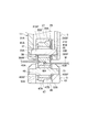
- FIG. 1 is a cross-sectional explanatory view showing a configuration of a step bending mold according to an embodiment of the present invention.
- a step bending mold 1 includes an upper mold 3 and a lower mold 5.
- the upper die 3 is provided so as to be movable up and down in an upper die holder 7 in a punch press (not shown), and the lower die 5 is detachably provided in a lower die holder 9 in the punch press.
- an upper die 3 is lowered by a striker ST provided on a punch press so as to be movable up and down, and stepped and bent into a plate-like workpiece W by upper and lower dies 3 and 5. Processing is performed.
- the upper die 3 includes a cylindrical upper die body (punch guide) 11 supported by the upper die holder 7 so as to be movable up and down.
- a punch body 13 is fitted in the upper die body 11 so as to be movable up and down.
- a punch driver 15 extending upward from the punch body 13 passes through a retainer collar 17 provided at an upper portion of the punch guide (upper die main body) 11 so as to be movable up and down.
- a punch head 19 is screwed to the upper end portion of the punch driver 15, and a stripper spring 21 is mounted between the punch head 19 and the retainer collar 17.
- An oil hole 23 penetrating vertically is formed in the axial center portion of the punch body 13.
- the oil hole 23 is freely connectable to an oil mist hole 25 formed in the striker ST, and receives supply of oil mist from the oil mist hole 25 when the striker ST is in contact with the punch head 19.
- the oil hole 23 communicates with a plurality of connection holes 23 ⁇ / b> A opened on the outer peripheral surface of the punch body 13.
- the oil mist supplied into the oil hole 23 lubricates between the outer peripheral surface of the punch body 13 and the inner peripheral surface of the punch guide 11 and also lubricates a stepped roller 29 described later.
- the stepped roller 29 is integrally provided with a large-diameter portion 29A and a small-diameter portion 29B in order to perform a step bending process on the plate-like workpiece W.
- an opening 27 is formed in a direction perpendicular to the axis of the punch guide 11. That is, the horizontal sectional shape of the opening 27 is a rectangular shape, and the longitudinal direction of the rectangular shape is orthogonal to the axis of the punch guide 11.
- a stepped roller 29 is rotatably provided in the opening 27. More specifically, by forming the opening 27, a pair of leg portions 31 ⁇ / b> A and 31 ⁇ / b> B are provided opposite to each other at the lower end portion of the upper mold body 11.
- the leg portions 31A, 31B are formed with inverted U-shaped cutout portions 33A, 33B that open downward. That is, the notches 33A and 33B have an inverted U-shape when viewed from the left and right directions in FIGS.
- Both ends of an upper roller support shaft 37 that rotatably supports the stepped roller 29 via a bearing 35 are engaged with the notches 33A and 33B.
- a fixing ring 39 for fixing both ends of the upper roller support shaft 37 in a state of being engaged with the notches 33A and 33B is provided through a fixture (not shown) such as a set screw. Is detachably attached to the lower end of the. Therefore, the upper roller support shaft 37 can be attached / detached to / from the punch guide 11 by attaching / detaching the fixing ring 39 to / from the punch guide 11.
- the fixing ring 39 has an inner surface 39AF that forms the same plane as the inner surface 31AF of the leg 31A, and an inner surface 39BF that forms the same plane as the inner surface 31BF of the leg 31B. It is formed. Then, in order to adjust the position of the stepped roller 29 in the axial direction (left-right direction in FIG. 2) with respect to the upper roller support shaft 37, between the inner surface 31AF of the leg portion 31A and the stepped roller 29 and the leg portion 31B. Between the inner surface 31BF and the stepped roller 29, spacers 41A and 41B having appropriate thicknesses are respectively interposed.
- the position of the stepped roller 29 can be adjusted in the left-right direction in FIG. 2 by reversing the arrangement of the spacers 41A and 41B and variously changing the thicknesses of the spacers 41A and 41B.
- the lower mold 5 includes a cylindrical lower mold main body 43 that is detachably supported by the lower mold holder 9.
- the lower mold body 43 is formed with an opening 45 in the vertical direction in order to arrange a stepped roller 47 described later.
- cutout portions 45A and 45B are provided so as to face each other.
- Both ends of the lower roller support shaft 51 are detachably supported by the notches 45A and 45B.
- the lower roller support shaft 51 is provided with a stepped roller (lower stepped roller) 47 that bends the workpiece W in cooperation with the stepped roller (upper stepped roller) 29 of the upper mold 3 via a bearing 49. And is supported rotatably.
- the stepped roller 47 includes a large diameter portion 47A and a small diameter portion 47B.
- the step between the large diameter portion 47A and the small diameter portion 47B is configured to be equal to the step between the large diameter portion 29A and the small diameter portion 29B in the upper stepped roller 29.
- the cross-sectional shape of the stepped portion is formed at a right angle on the upper and lower stepped rollers 29 and 47 so that the workpiece W can be bent at a right angle.
- the plate-like workpiece W is sandwiched between the stepped rollers 29 and 47 in the upper and lower molds 3 and 5. Then, by moving the workpiece W relative to the upper and lower molds 3 and 5, the workpiece W can be subjected to a linear or appropriately curved step bending process.
- the stepped rollers 29 and 47 in the upper and lower molds 3 and 5 are positioned in the left-right direction in FIG. 2 by variously changing the thickness of the spacers 41A and 41B: 53A and 53B. It can be adjusted. That is, as shown in FIG. 3, the axial distance L between the large diameter portion 29A of the upper stepped roller 29 and the large diameter portion 47A of the lower stepped roller 47 can be adjusted. Therefore, when performing the step bending of the workpiece W, the inclination angle of the stepped portion WA of the step bending portion of the workpiece W can be adjusted.
- the present invention is not limited to the above-described embodiments, and can be implemented in other forms by making appropriate changes.
- the large diameter portions 29A and 47A and the small diameter portions 29B and 47B of the upper and lower stepped rollers 29 and 47 in the upper and lower molds 3 and 5 are configured separately, and the large diameter portions 29A and 47A and the small diameter portions having different diameters are configured.
- the height difference of the stepped portion WA of the workpiece W can be set to various dimensions.
- the stepped roller and the roller support shaft may be integrated to adjust the position of the roller support shaft in the axial direction with respect to the upper mold body 11 and the lower mold body 43.
- the spacers 41A, 41B, etc. can be, for example, thrust bearings.
- the spacers 41A, 41B and the like can be thrust washers. In this case, it is possible to use a plurality of thrust washers.
- the step bending can be easily performed.
Landscapes
- Engineering & Computer Science (AREA)
- Mechanical Engineering (AREA)
- Bending Of Plates, Rods, And Pipes (AREA)
- Punching Or Piercing (AREA)
Abstract
上金型3及び下金型5にそれぞれ備えた上下の段付ローラ29,47の少なくとも一方を軸方向に移動し、上下の段付ローラ29,47における大径部29A,47Aの軸方向の間隔を調節した後にワークWの段曲げ加工を行う。板状のワークWに段曲げ加工を行う段曲げ金型は、上下に対向する上金型3及び下金型5にそれぞれ段付ローラ29,47を回転自在に備え、前記上下の金型3,5における少なくとも一方の段付ローラ29,47を、軸方向に位置調節可能に備えている。
Description
本発明は、板状のワークに段曲げ加工を行う方法及び段曲げ金型に係り、さらに詳細には、例えば段部を、ほぼ直角又は適宜に傾斜した段部になるように曲げ加工できる段曲げ加工方法及び段曲げ金型に関する。
板状のワークにZ形状の段曲げ加工を行う場合、一般的には、プレスブレーキにおける上下の金型の間にワークを挟圧することによって行われている。この場合、段曲げ加工は直線的に行われるものである。また、上下の金型に回転自在に備えた段付ローラの間にワークを挟み込んで段曲げ加工を行うことも提案されている(例えば特許文献1の図8(D)参照)。
特開平9-52129号公報
上記特許文献に記載の構成によれば、板状のワークに対して直線的な段曲げ加工及び曲線的な段曲げ加工を行うことが可能である。しかし、上金型における段付ローラの大径部と、下金型における段付ローラの大径部との軸方向の間隔は常に一定であるから、ワークの板厚が変わると、ワークの板厚に対応した上下の金型に変更する必要がある。また、ワークの板厚が同一であっても、段曲げ加工部分における段差部の傾斜角が異なる場合には、段差部の傾斜角に対応した段差部を有する上下の段付ローラを備えた上下の金型に変更する必要がある。
すなわち、ワークの板厚や段差部の傾斜角に対応して複数の上下の金型を必要とするものであった。
本発明は、前述のごとき問題に鑑みてなされたもので、板状のワークに段曲げ加工を行う段曲げ加工方法であって、上金型及び下金型にそれぞれ備えた上下の段付ローラの少なくとも一方を軸方向に移動し、上下の段付ローラにおける大径部の軸方向の間隔を調節した後にワークの段曲げ加工を行うことを特徴とするものである。
また、板状のワークに段曲げ加工を行う段曲げ金型であって、上下に対向する上金型及び下金型にそれぞれ段付ローラを回転自在に備え、前記上下の金型における少なくとも一方の段付ローラを、軸方向に位置調節可能に備えていることを特徴とするものである。
また、前記段曲げ金型において、前記上金型において段付ローラを回転自在に支持した上ローラ支持軸の両端側を、上金型における上型本体に着脱可能に支持して備え、前記段付ローラと前記上型本体との間に、適宜厚さのスペーサを介在自在に備えていることを特徴とするものである。
また、前記段曲げ金型において、前記下金型において段付ローラを回転自在に支持した下ローラ支持軸の両端側を、下金型本体における下型本体に着脱可能に支持して備え、前記段付ローラと前記下型本体との間に、適宜厚さのスペーサを介在自在に備えることを特徴とするものである。
本発明によれば、板状のワークの板厚が変わる場合や、段曲げ加工部分における段差部の傾斜角が異なる場合であっても、容易に対応して段曲げ加工を行い得る。
以下、図面を用いて本発明を実施した実施形態を説明する。
図1は、本発明の実施形態の段曲げ金型の構成を示す断面説明図である。
図1を参照するに、本発明の実施形態に係る段曲げ金型1は、上金型3と下金型5とを備えている。上金型3は、パンチプレス(図示省略)における上型ホルダ7に上下動自在に備えられており、下金型5は、パンチプレスにおける下型ホルダ9に着脱可能に備えられている。図1に示すように、パンチプレスに上下動自在に設けられたストライカSTによって上金型3が下降されるようになっており、上下の金型3,5によって板状のワークWに段曲げ加工が行われる。
上金型3は、上型ホルダ7に上下動自在に支持された円筒形状の上型本体(パンチガイド)11を備えている。この上型本体11内には、パンチボディ13が上下動自在に嵌入してある。そして、パンチボディ13から上方に延伸したパンチドライバ15は、パンチガイド(上型本体)11の上部に備えたリテーナカラー17を上下動自在に貫通してある。パンチドライバ15の上端部には、パンチヘッド19が螺着してあり、このパンチヘッド19とリテーナカラー17との間にはストリッパースプリング21が弾装してある。
パンチボディ13の軸心部には、上下に貫通した油孔23が形成してある。この油孔23は、ストライカSTに形成したオイルミスト孔25と接続自在であって、ストライカSTがパンチヘッド19に当接した状態にあるときに、オイルミスト孔25からオイルミストの供給を受ける。油孔23には、パンチボディ13の外周面に開口した複数の接続孔23Aが連通してある。
したがって、油孔23内へ供給されたオイルミストは、パンチボディ13の外周面とパンチガイド11の内周面との間の潤滑を行うと共に、後述する段付ローラ29の潤滑を行うものである。段付ローラ29は、板状のワークWに段曲げ加工を行うために、大径部29Aと小径部29Bとを一体的に備えている。
パンチガイド11の下端部には、当該パンチガイド11の軸心に対して直交する方向の開口部27が形成してある。すなわち、開口部27の水平方向の断面形状は長方形状であって、その長方形状の長手方向がパンチガイド11の軸心と直交してある。この開口部27内には、段付ローラ29が回転自在に備えられている。より詳細には、開口部27を形成したことにより、上型本体11の下端部には一対の脚部31A,31Bが対向して備えられている。そして、脚部31A,31Bには、下方向に開口した逆U字形状の切欠部33A,33Bが形成してある。すなわち、切欠部33A,33Bは、図1,2において左右方向から見た場合に、逆U字形状を呈するものである。
切欠部33A,33Bには、軸受35を介して段付ローラ29を回転自在に支持した上ローラ支持軸37の両端部が係合してある。そして、上ローラ支持軸37の両端部を、切欠部33A,33Bに係合した状態に固定するための固定用リング39が、止めねじなどのごとき固定具(図示省略)を介してパンチガイド11の下端部に着脱可能に取付けてある。したがって、パンチガイド11に対して固定用リング39を着脱することにより、パンチガイド11に対して上ローラ支持軸37を着脱することができる。
固定用リング39には、図2に示すように、脚部31Aの内面31AFと同一平面を形成する内面39AFが形成してあると共に、脚部31Bの内面31BFと同一平面を形成する内面39BFが形成してある。そして、段付ローラ29を、上ローラ支持軸37に対して軸方向(図2において左右方向)に位置調節するために、脚部31Aの内面31AFと段付ローラ29との間及び脚部31Bの内面31BFと段付ローラ29との間には、適宜厚さのスペーサ41A,41Bがそれぞれ介在してある。
したがって、各スペーサ41A,41Bの配置を逆にすることや各スペーサ41A,41Bの厚さを種々変更することにより、図2において、段付ローラ29を左右方向に位置調節できるものである。
下型5は、下型ホルダ9に着脱可能に支持される筒状の下型本体43を備えている。この下型本体43には、後述する段付ローラ47を配置するために、上下方向の開口部45が形成してある。そして、開口部45の両側には、上側に開口した切欠部45A,45B(図2参照)が対向配置して備えられている。この切欠部45A,45Bには、下ローラ支持軸51の両端部が着脱可能に支持されている。そして、下ローラ支持軸51は、上金型3の段付ローラ(上段付ローラ)29と協働してワークWに段曲げを行う段付ローラ(下段付ローラ)47を、軸受49を介して回転自在に支持している。
段付ローラ47は、大径部47Aと小径部47Bとを備えている。この大径部47Aと小径部47Bとの段差は、上段付ローラ29における大径部29Aと小径部29Bとの段差に等しく構成してある。そして、ワークWの段曲げを直角形状に行い得るように、上下の段付ローラ29,47に段差部の断面形状は直角に形成してある。
下金型5における下段付ローラ47を、図2において左右方向に位置調節するために、開口部45の一方の内面45AFと下段付ローラ47との間及び開口部45の他方の内面45BFと下段付ローラ47との間には、適宜厚さのスペーサ53A,53Bが介在してある。したがって、スペーサ53A,53Bの配置を逆にしたり、スペーサ53A,53Bの厚さを種々変更することにより、図2において、下段付ローラ47を左右方向に位置調節することができる。
以上のごとき構成において、図1,2に示すように、上下の金型3,5における段付ローラ29,47によって板状のワークWを挟み込む。そして、上下の金型3,5に対してワークWを相対的に移動することにより、ワークWに直線状又は適宜曲線の段曲げ加工を行うことができるものである。
ところで、既に理解されるように、上下の金型3,5における段付ローラ29,47は、スペーサ41A,41B:53A,53Bの厚さを種々変更することにより、図2において左右方向に位置調節することができるものである。すなわち、図3に示すように、上段付ローラ29における大径部29Aと下段付ローラ47における大径部47Aとの軸方向の間隔Lを調節することができる。したがって、ワークWの段曲げを行うに際して、ワークWの段曲げ加工部分の段差部WAの傾斜角を調節することができる。
換言すれば、ワークWの段曲げ加工部における段差部WAの傾斜角が種々の場合には、スペーサ41A,41B:53A,53Bの厚さを変更することにより容易に対応し得る。また、ワークWの厚さが種々異なる場合にも、図4に示すように、スペーサ41A,41B:53A,53Bの厚さを変更することにより容易に対応し得る。
ところで、本発明は、前述したごとき実施形態に限ることなく、適宜の変更を行うことにより、その他の形態で実施可能なものである。例えば、上下の金型3,5における上下の段付ローラ29,47の大径部29A,47Aと小径部29B,47Bとを別個に構成し、径の異なる大径部29A,47Aと小径部29B,47Bとを組合せることにより、ワークWの段差部WAの高低差を種々の寸法とすることも可能である。
また、上記説明においては、上下のローラ支持軸37,51に対して上下の段付ローラ29,47を軸方向に位置調節する場合について説明した。しかし、段付ローラとローラ支持軸とを一体構成として、上型本体11、下型本体43に対してローラ支持軸を軸方向に位置調節する構成とすることも可能である。
さらには、スペーサ41A,41B等を、例えばスラストベアリングとすることも可能である。また、スペーサ41A,41B等をスラストワッシャとすることも可能である。この場合スラストワッシャを複数枚重ねて使用することも可能である。
すなわち、種々の変更を行うことにより、前述した実施形態と異なる形態でもって実施することも可能なものである。
本発明によれば、板状のワークの板厚が変わる場合や、段曲げ加工部分における段差部の傾斜角が異なる場合であっても、容易に対応して段曲げ加工を行うことができる。
Claims (4)
- 板状のワークに段曲げ加工を行う段曲げ加工方法であって、上金型及び下金型にそれぞれ備えた上下の段付ローラの少なくとも一方を軸方向に移動し、上下の段付ローラにおける大径部の軸方向の間隔を調節した後にワークの段曲げ加工を行うことを特徴とする段曲げ加工方法。
- 板状のワークに段曲げ加工を行う段曲げ金型であって、上下に対向する上金型及び下金型にそれぞれ段付ローラを回転自在に備え、前記上下の金型における少なくとも一方の段付ローラを、軸方向に位置調節可能に備えていることを特徴とする段曲げ金型。
- 請求項2に記載の段曲げ金型において、前記上金型において段付ローラを回転自在に支持した上ローラ支持軸の両端側を、上金型における上型本体に着脱可能に支持して備え、前記段付ローラと前記上型本体との間に、適宜厚さのスペーサを介在自在に備えていることを特徴とする段曲げ金型。
- 請求項2又は3に記載の段曲げ金型において、前記下金型において段付ローラを回転自在に支持した下ローラ支持軸の両端側を、下金型本体における下型本体に着脱可能に支持して備え、前記段付ローラと前記下型本体との間に、適宜厚さのスペーサを介在自在に備えていることを特徴とする段曲げ金型。
Applications Claiming Priority (2)
| Application Number | Priority Date | Filing Date | Title |
|---|---|---|---|
| JP2016-034152 | 2016-02-25 | ||
| JP2016034152A JP6250079B2 (ja) | 2016-02-25 | 2016-02-25 | 段曲げ金型 |
Publications (1)
| Publication Number | Publication Date |
|---|---|
| WO2017146146A1 true WO2017146146A1 (ja) | 2017-08-31 |
Family
ID=59686283
Family Applications (1)
| Application Number | Title | Priority Date | Filing Date |
|---|---|---|---|
| PCT/JP2017/006825 Ceased WO2017146146A1 (ja) | 2016-02-25 | 2017-02-23 | 段曲げ加工方法及び段曲げ金型 |
Country Status (2)
| Country | Link |
|---|---|
| JP (1) | JP6250079B2 (ja) |
| WO (1) | WO2017146146A1 (ja) |
Cited By (1)
| Publication number | Priority date | Publication date | Assignee | Title |
|---|---|---|---|---|
| JP2019162638A (ja) * | 2018-03-19 | 2019-09-26 | 株式会社アマダホールディングス | 張り出し加工用金型及び張り出し加工方法 |
Families Citing this family (2)
| Publication number | Priority date | Publication date | Assignee | Title |
|---|---|---|---|---|
| CN110681771A (zh) * | 2019-09-18 | 2020-01-14 | 昌辉精密模具(黄山)有限公司 | 一种反锥度工件的成形装置 |
| JP7591629B1 (ja) | 2023-08-25 | 2024-11-28 | 株式会社アマダ | 段曲げ加工方法及び段曲げ加工における反り矯正方法 |
Citations (4)
| Publication number | Priority date | Publication date | Assignee | Title |
|---|---|---|---|---|
| JPS6089926U (ja) * | 1983-11-21 | 1985-06-20 | 日立金属株式会社 | 相互間隔調整ロ−ル |
| JPH0565418U (ja) * | 1992-02-07 | 1993-08-31 | 日鐵建材工業株式会社 | ロール位置設定装置 |
| JPH0952129A (ja) * | 1995-08-09 | 1997-02-25 | Amada Metrecs Co Ltd | パンチング加工方法およびその加工方法に用いるロールホーミング金型 |
| JPH11114630A (ja) * | 1997-10-07 | 1999-04-27 | Amada Metrecs Co Ltd | ベンディングマシン |
-
2016
- 2016-02-25 JP JP2016034152A patent/JP6250079B2/ja active Active
-
2017
- 2017-02-23 WO PCT/JP2017/006825 patent/WO2017146146A1/ja not_active Ceased
Patent Citations (4)
| Publication number | Priority date | Publication date | Assignee | Title |
|---|---|---|---|---|
| JPS6089926U (ja) * | 1983-11-21 | 1985-06-20 | 日立金属株式会社 | 相互間隔調整ロ−ル |
| JPH0565418U (ja) * | 1992-02-07 | 1993-08-31 | 日鐵建材工業株式会社 | ロール位置設定装置 |
| JPH0952129A (ja) * | 1995-08-09 | 1997-02-25 | Amada Metrecs Co Ltd | パンチング加工方法およびその加工方法に用いるロールホーミング金型 |
| JPH11114630A (ja) * | 1997-10-07 | 1999-04-27 | Amada Metrecs Co Ltd | ベンディングマシン |
Cited By (1)
| Publication number | Priority date | Publication date | Assignee | Title |
|---|---|---|---|---|
| JP2019162638A (ja) * | 2018-03-19 | 2019-09-26 | 株式会社アマダホールディングス | 張り出し加工用金型及び張り出し加工方法 |
Also Published As
| Publication number | Publication date |
|---|---|
| JP2017148846A (ja) | 2017-08-31 |
| JP6250079B2 (ja) | 2017-12-20 |
Similar Documents
| Publication | Publication Date | Title |
|---|---|---|
| CN104056883B (zh) | 一种板料多道次渐进式折弯成形装置 | |
| JP6250079B2 (ja) | 段曲げ金型 | |
| CN107427883B (zh) | 滚轧成形加工装置 | |
| CN103313809B (zh) | 滚子卷边装置 | |
| CN101125429A (zh) | 穿孔装置、穿孔用金属模具以及穿孔用金属模具的定位固定方法 | |
| CN108393402A (zh) | 一种带定位装置无拉痕折弯模下模 | |
| KR200355399Y1 (ko) | 조관기용 사이드 롤러 스탠드 | |
| JP2015213944A (ja) | ロール曲げ加工装置及びロール曲げ加工方法 | |
| US20230234117A1 (en) | Crowning method in press brake and press brake | |
| US20170368592A1 (en) | Press machine | |
| US7673487B2 (en) | Method for forming hollow shaft with a flange and product with hollow shaft formed by the same | |
| JP4479327B2 (ja) | Uoe鋼管製造工程におけるuプレス用ポンチ装置 | |
| JP2010284673A (ja) | 銅線の製造方法 | |
| CN104668600B (zh) | 深孔拉镗粗镗头 | |
| JP6650504B1 (ja) | 金型装置及びこれを用いた成形物の製造方法 | |
| CN2912857Y (zh) | 三维曲面柔性卷板装置 | |
| KR101838602B1 (ko) | 조관기의 파이프 외경 정밀규격 유지장치 | |
| JP3144606U (ja) | 直動軸受及びこれを使用した打抜き加工ユニット | |
| KR101836873B1 (ko) | 금형 교체가 필요없는 내진용 각관 성형방법 | |
| KR101482980B1 (ko) | 실시간 인장 투과전자현미경 관찰용 샘플 제조를 위한 롤금형 | |
| WO2016208659A1 (ja) | ロール成形装置 | |
| CN106734693A (zh) | 一种用于空间管件弯扭成形装置的送料机构 | |
| JP6458854B2 (ja) | リング状部材の製造装置及び製造方法、ラジアル転がり軸受の製造方法及び製造装置、並びに、回転機器の製造方法 | |
| JP4833288B2 (ja) | 金属ブランクからのリング圧延 | |
| JP2020037121A (ja) | 金属製部品の製造方法 |
Legal Events
| Date | Code | Title | Description |
|---|---|---|---|
| NENP | Non-entry into the national phase |
Ref country code: DE |
|
| 121 | Ep: the epo has been informed by wipo that ep was designated in this application |
Ref document number: 17756584 Country of ref document: EP Kind code of ref document: A1 |
|
| 122 | Ep: pct application non-entry in european phase |
Ref document number: 17756584 Country of ref document: EP Kind code of ref document: A1 |