WO2017146117A1 - 回転電動機の絶縁ボビン - Google Patents
回転電動機の絶縁ボビン Download PDFInfo
- Publication number
- WO2017146117A1 WO2017146117A1 PCT/JP2017/006673 JP2017006673W WO2017146117A1 WO 2017146117 A1 WO2017146117 A1 WO 2017146117A1 JP 2017006673 W JP2017006673 W JP 2017006673W WO 2017146117 A1 WO2017146117 A1 WO 2017146117A1
- Authority
- WO
- WIPO (PCT)
- Prior art keywords
- diameter side
- outer diameter
- stator core
- bobbin
- electric motor
- Prior art date
Links
Images


Classifications
-
- H—ELECTRICITY
- H02—GENERATION; CONVERSION OR DISTRIBUTION OF ELECTRIC POWER
- H02K—DYNAMO-ELECTRIC MACHINES
- H02K3/00—Details of windings
- H02K3/46—Fastening of windings on the stator or rotor structure
-
- H—ELECTRICITY
- H02—GENERATION; CONVERSION OR DISTRIBUTION OF ELECTRIC POWER
- H02K—DYNAMO-ELECTRIC MACHINES
- H02K9/00—Arrangements for cooling or ventilating
- H02K9/19—Arrangements for cooling or ventilating for machines with closed casing and closed-circuit cooling using a liquid cooling medium, e.g. oil
Definitions
- the present invention relates to an insulating bobbin of a rotary motor mounted on, for example, a vehicle, an industrial machine, etc., and more particularly to a technique that enables efficient cooling of a stator coil that is a heat source of the rotary motor.
- the main heat generation inside the rotary motor is the heat generation of the stator coil (copper loss) caused by energizing the stator coil and the heat generation (iron loss) caused by eddy currents generated in the magnetic material such as the stator core and rotor core. Is mentioned.
- stator coil copper loss
- iron loss iron loss
- Patent Documents 1 and 2 have been proposed as a method for cooling the inside of the rotary motor.
- an L-shaped guide plate that protrudes from the coil end is provided on the outer peripheral side of the coil of an insulating bobbin called an insulator, and cooling liquid ejected from above the coil end is caused to flow to the coil end. It has been proposed to cool the coil ends uniformly. Specifically, a hole penetrating in the radial direction is provided in the L-shaped guide plate of the insulating bobbin, and the guide plate receives the coolant sprayed from above the coil end. The cooling liquid received by the guide plate penetrates the coil end through the hole, thereby cooling the coil end.
- the insulating bobbin includes a main body portion that is fitted to the teeth of the stator core and has a coil wound around the outer periphery thereof, and the L-shaped guide plate that is disposed on the radially outer side of the main body portion. No guide plate is provided on the radially inner side of the main body portion as on the radially outer side.
- Patent Document 2 proposes that the coil end is sealed with a bobbin, and a through-hole leading to the coil end is provided at the top of the bobbin, and the cooling medium is made to flow through the through-hole so that the cooling medium is spread over the coil end. ing.
- the coolant discharged from above the coil end flows downward along the flow path formed on the outer diameter side of each insulating bobbin and flows from the hole of the insulating bobbin to the coil end.
- the coil end above the central axis of the stator is cooled.
- the coolant flowing through the coil end passes through the gap between the coils, when the coil is tightly wound, the flow of the coolant may deteriorate and the coil end may not be sufficiently cooled.
- simply flowing the coolant through the gap between the coils at the coil end cannot efficiently cool the inner peripheral side portion of the coil end where heat is easily generated.
- Patent Document 2 uses a bobbin to seal a coil end, fills the periphery of the coil end with a cooling medium, and cools the coil end.
- a cooling medium for the cooling medium exists only at one coil end.
- the coil end without the supply port may not be sufficiently cooled. There is no mention of cooling of the stator core.
- An object of the present invention is to provide an insulating bobbin for a rotary motor that can efficiently cool a stator coil with a coolant supplied from the outer diameter side of the stator core.
- An insulating bobbin for a rotary electric motor is an insulating bobbin that insulates a plurality of tooth portions arranged on the inner peripheral portion of an annular stator core in a rotary electric motor and a conductive wire arranged in a wound state on the outer periphery of the tooth portion.
- a cylindrical lead wire winding part in which a tooth part insertion hole into which the tooth part is inserted is formed and the conductive wire is wound in a laminated form on the outer peripheral surface, a radial outer diameter end of the stator core in the conductive wire winding part, and An outer diameter side flange and an inner diameter side flange projecting from the inner diameter end along the direction in which the conductors are laminated, and the diameter of the stator core on the outer peripheral surface portion facing the axial direction of the stator core in the conductor winding portion An outer circumferential groove extending in the direction is formed, and a first through hole that penetrates in the radial direction of the stator core and communicates with the outer circumferential groove is formed in the outer diameter side flange.
- the cooling liquid when the cooling liquid is supplied from the outer diameter side in the stator core radial direction, the cooling liquid is received by the outer diameter surface of the outer diameter side flange of the insulating bobbin.
- the coolant received by the outer diameter surface of the outer diameter side flange passes through the first through hole of the outer diameter side flange and enters the outer peripheral groove formed on the outer peripheral surface of the conductor winding portion.
- the outer peripheral groove is in contact with the inner peripheral surface of the coil end. For this reason, the coil end is cooled from the inner peripheral side where heat is easily generated while the coolant flows through the outer peripheral groove to the inner diameter side in the stator core radial direction. Further, while flowing through the outer peripheral groove, a part of the cooling liquid penetrates into the gaps between the coil ends and cools the coil ends from the inside.
- a second through hole penetrating in the radial direction of the stator core is formed in a coil end outer diameter side portion extending in the axial direction of the stator core from the conductor winding portion in the outer diameter side flange portion. Also good.
- the coolant received by the outer diameter surface of the outer diameter side flange of the insulating bobbin enters the outer peripheral groove through the first through hole, and also passes through the second through hole. It penetrates into the gap between the conductors from the outer diameter side of the coil end. As a result, the coolant spreads well over the entire coil end, and the coil end can be cooled more efficiently.
- the first through hole and the second through hole may be arranged such that their circumferential positions with respect to the axis of the stator core are shifted from each other. That is, the first through hole and the second through hole are staggered. As described above, the staggered arrangement allows the first through hole and the second through hole in the outer diameter side flange without increasing the width of the outer diameter side flange in the stator core axial direction more than necessary. Can be provided.
- an inner peripheral groove extending in the radial direction of the stator core may be formed in an inner peripheral surface portion of the conductive wire winding portion that faces the surface facing the axial direction of the stator core.
- the inner circumferential groove and the outer circumferential groove may be arranged such that their circumferential positions with respect to the axis of the stator core are shifted from each other. That is, the inner circumferential groove and the outer circumferential groove are staggered. As described above, the staggered arrangement allows the inner and outer grooves to be provided in the conductor winding portion without making the conductor winding portion thicker than necessary.
- a ridge projecting outward in the radial direction of the stator core may be formed at the tip of the coil end outer diameter side portion of the outer diameter side flange.
- the coolant received at the outer diameter side flange is less likely to flow out from the tip of the coil end outer diameter side portion, and the coolant is retained on the outer diameter surface of the outer diameter side flange. be able to. For this reason, a lot of coolant can be made to enter the first through hole.
- the second through hole and the inner peripheral groove are provided, a large amount of cooling liquid can be caused to enter the second through hole and the inner peripheral groove.
- FIG. 10 is a perspective view of the insulating bobbin and the stator core component as viewed from a direction different from FIG. 9.
- FIG. 1 is a longitudinal sectional view of a rotary motor.
- the rotary electric motor includes a rotary shaft 1 that is disposed sideways, a rotor 2 that is integrally fixed to the rotary shaft 1, a stator 3 that is disposed on the outer periphery of the rotor 2, And a housing 4 that covers and fixes the stator 3.
- a radial gap is provided between the rotor 2 and the stator 3.
- the motor shaft direction refers to the direction of the axis O of the rotary shaft 1.
- the housing 4 is composed of a main housing 4a whose one end surface in the axial direction is open, and a side housing 4b which closes the open end surface of the main housing 4a.
- the main housing 4a and the side housing 4b are fixed by a housing fixing bolt 5.
- the rotary shaft 1 is rotatably supported by rolling bearings (ball bearings) 6 and 7 provided in the main housing 4a and the side housing 4b, respectively.
- a preload spring 8 is interposed between the inner ring of the rolling bearing 6 and the step portion 1 a of the rotating shaft 1, and a predetermined preload is applied to the rolling bearings 6 and 7 by the preload spring 8.
- An oil seal 9 is provided in the gap between the main housing 4a and the rotary shaft 1.
- the rotor 2 includes a rotor core 10 and a plurality of permanent magnets 11 built in the rotor core 10.
- the permanent magnets 11 are arranged at regular intervals in the circumferential direction.
- a flange-shaped rotor fixing member 12 is integrally formed on the rotary shaft 1.
- the rotor fixing member 12 has a cylindrical portion 12a formed at the radially outer end, and a flange portion 12b extending radially outward from one axial end of the cylindrical portion 12a.
- the rotor core 10 is fitted to the outer periphery of the cylindrical portion 12a of the rotor fixing member 12, and the rotor core 10 and the permanent magnet 11 are sandwiched from both sides in the motor axial direction by the flange portion 12b and the magnet pressing member 13. Thereby, the rotor 2 is fixed to the rotating shaft 1.
- the magnet pressing member 13 is fixed to the cylindrical portion 12 a of the rotor fixing member 12 by a rotor fixing bolt 14.
- the rotor fixing member 12 is formed integrally with the rotating shaft 1, but the rotor fixing member 12 may be separate from the rotating shaft 1.
- the stator 3 includes a stator core 20 and a stator coil 21.
- the stator core 20 is made of, for example, a soft magnetic material.
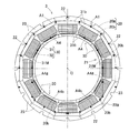
- FIG. 2 is a view of the stator 3 as viewed from the central axis direction.
- the stator core 20 is formed with a plurality of teeth 20b arranged radially around the axis O of the rotary shaft 1 (see FIG. 1) on the inner periphery of the annular portion 20a.
- the cross-sectional shape (not shown) obtained by cutting the tooth portion 20b along a plane perpendicular to the motor radial direction is, for example, a rectangle.
- a plurality of stator fixing bolt insertion notches 22 extending in the axial direction of the stator 3 are provided on the outer periphery of the annular portion 20a.
- the motor radial direction is a direction orthogonal to the axis O of the rotary shaft 1 (FIG. 1), and coincides with the radial direction of the stator core 20 in the assembled state. Further, the axial direction of the stator core 20 in the assembled state coincides with the motor axial direction.
- the stator core 20 of this embodiment is configured by combining a plurality of stator core components 23 having the same shape in the circumferential direction.
- Each stator core component 23 has one tooth portion 20b and one notch 22 for inserting a stator fixing bolt. Adjacent stator core components 23 are combined by engagement of the engaging projection 23a and the engagement recess 23b.
- the stator core 20 is composed of a plurality of stator core components 23, and is installed in the housing 4 as shown in FIG. That is, the annular portion 20a is fitted to the inner periphery of the main housing 4a, and one axial end surface of the annular portion 20a is in contact with the step surface 24 of the main housing 4a.
- the stator fixing bolts 25 are inserted into the notches 22 at arbitrary plural positions among the plurality of notches 22 for inserting the stator fixing bolts, and screwed into the screw holes 26 formed in the step surface 24. Thereby, the stator core 20 is fixed to the housing 4.
- the stator coil 21 is a concentrated winding type and includes a plurality of individual coils 30 provided on each tooth portion 20 b of the stator core 20.
- Each individual coil 30 includes an insulating bobbin 31 that surrounds the outer periphery of the tooth portion 20b, and a conductive wire 32 wound around the insulating bobbin 31 in a laminated manner.
- the insulating bobbin 31 insulates the tooth part 20b and the conducting wire 32 arranged around the outer periphery of the tooth part 20b.
- the insulating bobbin 31 includes a cylindrical wire winding portion 31 a into which the tooth portion 20 b of the stator core 20 is inserted, and an outer diameter end in the motor radial direction of the wire winding portion 31 a.
- the outer diameter side flange 31b protrudes along the lamination direction of the conducting wire 32
- the inner diameter side flange 31c protrudes along the lamination direction from the inner diameter end of the conductor winding portion 31a in the motor radial direction.
- the inside of the cylindrical conducting wire winding portion 31a constitutes a tooth portion insertion hole 33 into which the tooth portion 20b of the stator core 20 is inserted, and the conducting wire 32 is wound around the outer peripheral surface of the conducting wire winding portion 31a.
- the outer diameter side flange 31b constitutes a coil end outer diameter side portion 31ba extending in the motor axial direction from the conductor winding portion 31a.
- the inner diameter side flange 31c constitutes a coil end inner diameter side portion 31ca extending in the motor axial direction from the conductor winding portion 31a.
- the coil end 30a of the individual coil 30 is located.
- the coil end outer diameter side portion 31ba and the coil end inner diameter side portion 31ca are disposed on both sides in the motor axial direction with respect to the conductor winding portion 31a.
- the insulating bobbin 31 has a first through hole 36 (FIG. 3), an outer peripheral groove 37 (FIG. 3), a second through hole 38 (FIG. 4), and an inner peripheral groove 39 (FIG. 4). Yes.
- the first through-hole 36 is located at the boundary between the coil end outer diameter side portion 31ba and the conductor winding portion 31a in the outer diameter side flange 31b, and is in the motor radial direction (radial direction of the stator core 20).
- the first through hole 36 is, for example, a circular hole.
- the outer peripheral groove 37 is a groove extending in the motor radial direction formed in the outer peripheral surface portion facing the motor axial direction (axial direction of the stator core 20) in the conductor winding portion 31 a, and the outer diameter end is formed in the first through hole 36. Communicate.
- the outer peripheral groove 37 is, for example, a square groove.
- the second through hole 38 is located in the motor axial direction intermediate portion of the coil end outer diameter side portion 31ba and penetrates in the motor radial direction.
- the second through hole 38 is, for example, a circular hole.
- the inner circumferential groove 39 is formed in an inner circumferential surface portion of the conducting wire winding portion 31a facing the motor axial direction and extends in the motor radial direction.
- the inner peripheral groove 39 is, for example, a square groove.
- FIG. 5 is a view of the insulating bobbin 31 as seen from the outer diameter side.
- the insulating bobbin 31 shown in FIG. 3 is the III-III cross section of FIG. 5, and the insulating bobbin 31 shown in FIG. 4 is the IV-IV cross section of FIG.
- a plurality of first through holes 36 shown in FIG. 5 are provided in a range in contact with the conductor winding portion 31a in the circumferential direction of the coil end outer diameter side portion 31ba.
- a plurality of second through holes 38 are provided over a wider range than the first through hole 36 in the circumferential direction of the coil end outer diameter side portion 31ba of the outer diameter side flange 31b.
- the first through holes 36 and the second through holes 38 are arranged in a staggered manner.
- the first through hole 36 and the second through hole 38 can be provided in the side flange portion 31b.
- FIG. 6 is a cross-sectional view of the insulating bobbin 31 cut along a plane perpendicular to the radial direction.
- a plurality of outer circumferential grooves 37 are provided at circumferential positions corresponding to the first through holes 36 on the outer circumferential surface of the conductor winding portion 31a.
- a plurality of inner circumferential grooves 39 are provided at positions that are staggered with the outer circumferential grooves 37 on the inner circumferential surface of the conductor winding portion 31a.
- the insulating bobbin 31 includes two bobbin divided bodies 31A and 31B that are symmetrical to each other and are divided into two in the motor axial direction.
- the conductive wire winding part 31a is formed in a cylindrical shape.
- Each bobbin divided body 31A, 31B has one coil end outer diameter side portion 31ba and one coil end inner diameter side portion 31ca.
- each of the bobbin divided bodies 31 ⁇ / b> A and 31 ⁇ / b> B has an inner peripheral side joint portion 41 and an outer peripheral side joint portion 42.
- the inner circumferential side joining portion 41 and the outer circumferential side joining portion 42 overlap each other. For this reason, when the stator 3 is assembled as shown in FIG. 2, insulation between the stator core 20 and the conductive wire 32 can be ensured.
- FIG. 9 to 11 show the assembled state of the stator 3.
- 9 is a perspective view of the insulating bobbin 31 and the stator core component 23
- FIG. 10 is a perspective view of the insulating bobbin 31 and the stator core component 23 as seen from different directions
- FIG. 11 is a view before combining the pair of bobbin divided bodies 31A and 31B.
- FIG. 6 is a perspective view of an insulating bobbin 31 and a stator core component 23 showing a state. As shown in FIGS. 9 to 11, after the insulating bobbin 31 is attached to the tooth portion 20 b of each stator core component 23, the stator core components 23 with the insulating bobbin 31 are combined with each other.
- the inner diameter surface 43 of the inner diameter side flange portion 31 c has an arc shape centered on the axis O (FIG. 1) of the rotating shaft 1.
- the outer diameter surface 44 of the outer diameter side flange 31b has a flat portion 44a in a range in contact with the conductive wire winding portion 31a, and both side portions 44b are the axis O of the rotating shaft 1. It has an arc shape centered at.
- the circumferential side surface 45 of the outer diameter side flange 31b and the circumferential side surface 46 of the inner diameter side flange 31c are located on the same plane passing through the axis O of the rotary shaft 1.
- the outer diameter side flange portions 31b and the inner diameter side flange portions 31c of the adjacent insulating bobbins 31 are in contact with each other without a gap.
- the outer diameter side flanges 31b and the inner diameter side flanges 31c of the adjacent insulating bobbins 31 are in contact with each other without any gap. Only the insulating bobbin 31 of the individual coil 30 located at the top may be in contact with no gap.
- the “individual coil 30 located in the upper part” does not necessarily have to be all the individual coils 30 on the upper half circumference, and is, for example, the individual coil 30 having a quarter to 3 circumference including the upper end. Also good.
- the housing 4 is provided with a coolant supply means 50 for supplying coolant onto the insulating bobbin 31 of the upper individual coil 30.
- the coolant is, for example, oil.
- the coolant supply means 50 includes a coolant supply port 51 provided in the upper portion of the main housing 4a, a flow path 52 communicating with the supply port 51 and extending in the motor axial direction, and the motor axial direction of the flow path 52 Are provided with dripping ports 53 and 54 for communicating the vicinity of both ends and the inside of the housing 4.
- the dripping ports 53 and 54 are located above the insulating bobbin 31 of the individual coil 30 located at the upper part. In this embodiment, the dripping ports 53 and 54 are located directly above the coil end outer diameter side portion 31ba of the outer diameter side flange 31b in the insulating bobbin 31 of the uppermost individual coil 30.
- the supply port 51 is connected to a coolant supply device (not shown) which is provided separately from the rotary motor or attached to the rotary motor.
- a cooling liquid discharge port 55 is provided at a lower portion of the side housing 4b.
- the upper end position of the discharge port 55 is positioned lower than the lower end position of the rotor 2.
- the discharge port 55 is connected to the coolant supply device via an oil reservoir (not shown).
- the flow of coolant in this rotary motor will be described.
- the coolant sent from the coolant supply apparatus passes through the supply port 51 and the flow path 52 and is dropped from the dropping ports 53 and 54.
- the dropped coolant is received at the coil end outer diameter side portion 31ba (FIGS. 3 and 4) of the outer diameter side flange 31b of the uppermost insulating bobbin 31.
- the coolant received at the coil end outer diameter side portion 31ba enters the first through hole 36, the second through hole 38, and the inner peripheral groove 39 and flows downward.
- the protrusion 35 protruding outward is formed at the tip of the coil end outer diameter side portion 31ba, the received coolant is unlikely to flow out to the tip end side of the coil end outer diameter side portion 31ba.
- the coolant can be retained on the portion 31b. For this reason, a large amount of coolant can enter the first through hole 36, the second through hole 38, and the inner circumferential groove 39.
- the first through hole 36, the second through hole 38, and the inner circumference of the uppermost insulating bobbin 31 are arranged.
- the coolant that has not entered the groove 39 flows to the lower insulating bobbin 31 along the outer diameter surface of the outer diameter side flange 31b, as indicated by an arrow A1 in FIG. Thereafter, the coolant that has flowed into the lower insulating bobbin 31 enters the first through hole 36, the second through hole 38, and the inner peripheral groove 39 of the lower insulating bobbin 31.
- the coolant that has not entered the first through hole 36, the second through hole 38, and the inner peripheral groove 39 of any of the insulating bobbins 31 in the upper half is on the outer diameter side of the upper and lower intermediate insulating bobbins 31M. It falls from the collar part 31b.
- the coolant that has entered the first through hole 36 flows along the inner periphery of the coil end 30a through the outer peripheral groove 37 as shown by an arrow A2 in FIG. During this time, the coil end 30a is cooled from the inner peripheral side where heat is easily generated. Further, while flowing through the outer peripheral groove 37, a part of the cooling liquid penetrates into the gap between the conductive wires 32 and cools the coil end 30 a also from the inside.
- the coolant that has entered the second through-hole 38 penetrates into the gap between the conductors 32 from the upper side of the coil end 30a as indicated by an arrow A3 in FIG. As a result, the coolant spreads well over the entire coil end 30a, and the coil end 30a can be cooled more efficiently.
- the coolant that has entered the first through hole 36 and the second through hole 38 passes through the outer circumferential groove 37 or the coil end 30a, and is finally received by the inner diameter side flange 31c. Since the inner diameter side flanges 31c of the adjacent insulating bobbins 31 are arranged in contact with each other without a gap, as shown by an arrow A4 in FIG. Coolant flows to the individual coil 30 on the lower side.
- the coolant that has entered the inner circumferential groove 39 flows between the tooth portion 20b of the stator core 20 and the conductor winding portion 30a.
- gear part 20b of the stator core 20 can be cooled efficiently.
- the outer diameter side flanges 31b of the adjacent individual coils 30 of the upper individual coil 30 are arranged in contact with each other without a gap, the cooling received by the outer diameter side flange 31b of the uppermost individual bobbin 30
- the liquid flows through the outer diameter side flange 31bc of each individual coil 30 to the individual coil 30 on the lower side. Thereafter, the coolant that has flowed into the individual coil 30 on the lower side enters the inner peripheral groove 39 of the individual coil 30 on the lower side. For this reason, the tooth
- the coolant used for cooling the stator coil 21 and the stator core 20 is collected at the bottom of the housing 4 and discharged from the outlet 55 to the outside of the housing 4. Since the upper end position of the discharge port 55 is lower than the lower end position of the rotor 2, the lower end of the rotor 2 is not immersed in the coolant accumulated at the bottom of the housing 4. For this reason, the rotor 2 rotating at high speed does not scoop up the coolant and stir. Note that the lower portion of the stator 3 is immersed in the coolant accumulated at the bottom of the housing 4.
- the coolant discharged from the discharge port 55 is returned to the coolant supply device via the oil sump, and is used again for cooling the rotary motor.
- the stator coil 21 and the stator core 22 can be efficiently cooled by the coolant supplied from the upper part of the housing 4. As a result, the output of the rotary motor can be improved.
- FIG. 12 and 13 show an insulating bobbin different from the examples of FIGS.
- FIG. 12 is a perspective view of one bobbin divided body of the insulating bobbin
- FIG. 13 is a perspective view of the bobbin divided body seen from another direction.
- the bobbin divided body 31A (31B) of the insulating bobbin includes first and second recesses 61 for temporarily retaining the coolant on the inner diameter surface of the outer diameter side flange 31b and the outer diameter surface of the inner diameter side flange 31c.
- a plurality of 62 are formed.
- Both the first recess 61 (FIG. 13) formed on the inner diameter surface of the outer diameter side flange 31b and the second recess 62 (FIG. 12) formed on the outer diameter surface of the inner diameter side flange 31c are A groove shape extending in the direction in which the individual bobbins 30 are arranged.
- the number of the first and second recesses 61 and 62 is two.
- One first recess 61 is located between the first through hole 36 and the second through hole 38, and the other first recess 61 is located outside the second through hole 38 in the motor axial direction.
- the two second recesses 62 are also formed at substantially the same motor axial position as the two first recesses 61.
- the 1st and 2nd recessed parts 61 and 62 are formed in the internal diameter surface of the outer diameter side collar part 31b, and the outer diameter surface of the inner diameter side collar part 31c, the 1st and 2nd recessed part 61 will be formed. , 62 can temporarily hold the coolant. Therefore, the time for which the coolant comes into contact with the coil end (not shown) becomes longer, and the cooling effect is improved. Further, since the first and second recesses 61 and 62 are groove-shaped, the flow of the coolant from the upper individual coil 30 to the lower individual coil 30 becomes smooth.
- Only one of the recesses may be provided without providing both the first recess 61 and the second recess 62. Even in that case, the cooling effect can be improved as compared with the case where the first and second recesses 61 and 62 are not provided.
- FIG. 14 shows another embodiment of the rotary motor.
- the coolant supply means 50 is provided with a notch 22 for inserting a stator fixing bolt located at the top of the stator core 20 for the coolant. It is used as a flow path. That is, the flow path 52 and the dripping ports 53 and 54 (FIG. 1) are not provided in the main housing 4a, and the supply port 51 is communicated with the intermediate portion in the motor axial direction of the notch 22 for inserting the stator fixing bolt. ing.
- the coolant supplied to the supply port 51 flows to both sides in the motor axial direction through the notches 22 for inserting the stator fixing bolts, and is dropped on the outer diameter side flange 31b of the insulating bobbin 31.
- the subsequent flow of the coolant is the same as that of the rotary motor of the embodiment of FIG.
- the flow path 52 and the dripping ports 53 and 54 are provided in the main housing 4a as in the rotary motor of the embodiment of FIG. There is no need. As a result, the processing of the main housing 4a is facilitated. Except this, it is the same structure as the rotary electric motor of the embodiment shown in FIG.
- the invention of the insulating bobbin 31 having the outer peripheral groove 37 and the first through hole 36 has been described.
- the present invention can also be applied to a rotary electric motor having an insulating bobbin having a different configuration.
- Examples of such rotary electric motors include the following modes 1 to 6.
- the rotary electric motor of this aspect 1 is A rotation axis arranged sideways; A rotor integrally fixed to the rotating shaft; A stator disposed on the outer periphery of the rotor; A housing that covers and fixes the stator, and rotatably supports the rotating shaft via a plurality of bearings,
- the stator comprises a stator core and a stator coil,
- the stator core has a plurality of teeth arranged radially around the axis of the rotation shaft,
- the stator coil is composed of a plurality of individual coils provided on each tooth portion, These individual coils include an insulating bobbin that surrounds the outer periphery of the tooth portion, and a conductive wire wound around the insulating bobbin.
- Each of the insulating bobbins is A tooth portion insertion hole into which the tooth portion of the stator core is inserted is formed, and a cylindrical lead wire winding portion on which an outer peripheral surface is wound with the lead wire, and An outer diameter side flange projecting along the laminating direction of the conductor from the outer diameter end of the motor radial direction which is the radial direction with respect to the rotating shaft in the conductor winding portion; An inner diameter side flange protruding from the inner diameter end of the conductive wire winding portion along the lamination direction of the conductive wire,
- the insulating bobbins of the individual coils located in the upper half of the plurality of individual coils are arranged in a state in which the outer diameter side flanges and the inner diameter side flanges of the adjacent individual coils are in contact with each other without a gap, And a through-hole penetrating in the motor radial direction is formed in a coil end outer diameter side portion extending in the motor axial direction which
- the coolant is supplied from the upper portion of the housing by the coolant supply means, and the coolant is received by the outer diameter surface of the outer diameter side flange of the insulating bobbin of the individual coil located in the upper half.
- the coolant received at the outer diameter surface of the outer diameter side flange passes through the through hole of the outer diameter side flange and penetrates into the gap between the conductors from the upper side of the coil end. As a result, the coolant spreads well over the entire coil end, and the coil end can be efficiently cooled.
- the coolant that has not entered the through hole of the upper insulating bobbin flows to the lower insulating bobbin through each outer diameter side flange, and enters the through hole of the lower insulating bobbin. Further, the coolant that has flowed to the lower end of the coil end is received by the inner diameter side flange, and penetrates into the gap between the coil ends of the individual coils adjacent to the lower side.
- the insulation bobbin of the individual coil located in the upper half is disposed in a state where the outer diameter side flanges and the inner diameter side flanges of the insulation bobbins of adjacent individual coils are in contact with each other without any gap, so that the coolant is not It flows from the upper individual coil to the lower individual coil through the outer diameter side collar and the inner diameter side collar without spilling. For this reason, the cooling liquid can be sufficiently distributed to all of the individual coils located in the upper half, and can be efficiently cooled.
- the individual coil located in the lower half is cooled by the coolant supplied by flowing from the individual coil located in the upper half or the coolant supplied by dropping.
- the above coolant flow can be realized only by devising the shape of the insulating bobbin. No dedicated means for guiding the coolant to the coil end is required. For this reason, it is possible to efficiently cool the stator coil with a simple configuration.
- each of the insulating bobbins on the entire circumference is desirably arranged in a state where the outer diameter side flanges and the inner diameter side flanges of adjacent insulating bobbins are in contact with each other without any gap.
- Aspect 2 not only the individual coils located in the upper half, but also the outer diameter side flanges and the inner diameter side flanges of the adjacent insulating bobbins are arranged in contact with each other without any gaps for all individual coils.
- the coolant spreads even better to the individual coils located in the lower part. For this reason, the cooling effect of the coil end of the individual coil located in the lower part is improved.
- the insulating bobbin of the individual coil located in the upper half of the plurality of individual coils is arranged in the motor radial direction on an inner peripheral surface portion of the conductor winding portion facing the motor axial direction.
- An extending inner circumferential groove may be formed.
- a part of the cooling oil received by the outer diameter surface of the outer diameter side flange of the insulating bobbin of the individual coil located in the upper half passes through the inner peripheral groove and the tooth portion of the stator core and the insulating bobbin. It flows between the conductor winding parts. Thereby, the stator core can be efficiently cooled.
- the insulating bobbin of the individual coil located in the upper half of the plurality of individual coils is disposed at a tip of the coil end outer diameter side portion of the outer diameter side flange.
- a protrusion that protrudes toward the outer diameter side may be formed.
- the cooling liquid received by the outer diameter side flange is unlikely to flow down from the tip of the coil end outer diameter side portion, and the cooling liquid is placed on the outer diameter side flange. Can be stopped. For this reason, a large amount of cooling liquid can enter the through hole.
- a recess that temporarily holds the coolant is formed on at least one of the inner diameter surface of the outer diameter side flange and the outer diameter surface of the inner diameter side flange of the insulating bobbin. May be. According to the aspect 5, since the cooling liquid can be temporarily retained in the concave portion, the time during which the cooling liquid contacts the coil end can be lengthened, and the cooling effect of the coil end can be improved.
- the concave portion may have a groove shape extending in the arrangement direction of the individual bobbins.
- the recess has the groove shape, the flow of the coolant from the upper individual coil to the lower individual coil becomes smooth.
- the present invention is not limited to the above embodiment, and various additions, changes, or deletions are possible without departing from the gist of the present invention. Therefore, such a thing is also included in the scope of the present invention.
Landscapes
- Engineering & Computer Science (AREA)
- Power Engineering (AREA)
- Insulation, Fastening Of Motor, Generator Windings (AREA)
Abstract
絶縁ボビン(31)は、導線巻回部(31a)と外径側鍔部(34b)と内径側鍔部(34c)とを有する。導線巻回部(31a)は、ステータコア(20)の歯部(20b)が挿入される歯部挿入孔(33)が形成され、外周面に導線(32)が積層状に巻かれている。外径側鍔部(34b)および内径側鍔部(34c)は、導線巻回部(31a)におけるステータコア径方向の外径端および内径端からそれぞれ導線(32)の積層方向に沿って突出する。導線巻回部(31a)におけるステータコア軸方向を向く外周面部分に、ステータコア径方向に延びる外周溝(37)が形成され、かつ外径側鍔部(31b)に、ステータコア径方向に貫通し外周溝(37)に連通する第1の貫通孔(36)が形成されている。
Description
この出願は、2016年2月26日出願の特願2016-035447および特願2016-035448の優先権を主張するものであり、その全体を参照により本願の一部をなすものとして引用する。
この発明は、例えば車両、産業用機械等に搭載される回転電動機の絶縁ボビンに関し、特に回転電動機の発熱源であるステータコイルを効率良く冷却することを可能にする技術に関する。
近年、回転電動機の小形化、高出力化が進んでいる。それに伴い、回転電動機内部での発熱量の増加が課題となっている。回転電動機内部の発熱の主なものとしては、ステータコイルに通電することによるステータコイルの発熱(銅損)と、ステータコア、ロータコア等の磁性体に渦電流が発生することによる発熱(鉄損)とが挙げられる。これらの発熱によって温度上昇した回転電動機の内部、特にステータコイルおよびステータコアを効率良く冷却することが、回転電動機の出力を向上させるうえで重要である。
回転電動機の内部を冷却する手法として、例えば以下の特許文献1,2が提案されている。特許文献1には、インシュレータと称している絶縁ボビンのコイル外周側に、コイルエンドより突出したL字状の案内板を設け、コイルエンドの上方から噴出される冷却液をコイルエンドに流すことで、コイルエンドを均一に冷却することが提案されている。具体的には、絶縁ボビンのL字状の案内板に、径方向に貫通する孔が設けられており、コイルエンドの上方から噴出される冷却液を案内板が受ける。この案内板で受けられた冷却液が前記孔を通ってコイルエンドに浸透することで、コイルエンドを冷却する。なお、絶縁ボビンは、ステータコアのティースに嵌合し外周にコイルが巻回される本体部と、この本体部の径方向外側に配置された前記L字状の案内板とを有する。本体部の径方向内側には、径方向外側のような案内板が設けられていない。
特許文献2には、コイルエンドをボビンにより密封構造とし、ボビン上部にコイルエンドに通じる貫通孔を設け、この貫通孔に冷却媒体を流すことで、コイルエンドに冷却媒体を行き渡らせることが提案されている。
特許文献1の手法は、コイルエンドの上方から放出された冷却液が、各絶縁ボビンの外径側に形成された流路を伝って下方に流れると共に、絶縁ボビンの孔からコイルエンドに流れることで、ステータの中心軸よりも上部のコイルエンドを冷却する。しかしながら、コイルエンドを流れる冷却液はコイル間の隙間を通るため、コイルが密に巻かれている場合、冷却液の流れが悪くなって、コイルエンドを十分に冷却ができない可能性がある。また、単にコイルエンドのコイル間の隙間に冷却液を流すだけでは、熱が籠り易いコイルエンドの内周側の部分を効率良く冷却できない。
特許文献2の手法は、ボビンを利用してコイルエンドを密閉し、コイルエンドの周囲を冷却媒体で満たして、コイルエンドを冷却するようにしている。しかしながら、コイルエンドを密閉すると、ボビンの構造が複雑となる。また、冷却媒体の供給口が片方のコイルエンドにのみ存在するため、供給口の無いコイルエンドは十分に冷却されない可能性がある。ステータコアの冷却については言及されていない。
この発明の目的は、ステータコアの外径側から供給される冷却液によって、ステータコイルを効率良く冷却することができる回転電動機の絶縁ボビンを提供することである。
この発明の回転電動機の絶縁ボビンは、回転電動機における環状のステータコアの内周部に並ぶ複数の歯部とこの歯部の外周に巻回状態で配置される導線とを絶縁する絶縁ボビンであって、
前記歯部が挿入される歯部挿入孔が形成され外周面に前記導線が積層状に巻かれる筒状の導線巻回部と、この導線巻回部における前記ステータコアの径方向の外径端および内径端からそれぞれ前記導線の積層方向に沿って突出する外径側鍔部および内径側鍔部とを有し、前記導線巻回部における前記ステータコアの軸方向を向く外周面部分に前記ステータコアの径方向に延びる外周溝が形成され、かつ前記外径側鍔部に前記ステータコアの径方向に貫通し前記外周溝に連通する第1の貫通孔が形成されている。
前記歯部が挿入される歯部挿入孔が形成され外周面に前記導線が積層状に巻かれる筒状の導線巻回部と、この導線巻回部における前記ステータコアの径方向の外径端および内径端からそれぞれ前記導線の積層方向に沿って突出する外径側鍔部および内径側鍔部とを有し、前記導線巻回部における前記ステータコアの軸方向を向く外周面部分に前記ステータコアの径方向に延びる外周溝が形成され、かつ前記外径側鍔部に前記ステータコアの径方向に貫通し前記外周溝に連通する第1の貫通孔が形成されている。
この構成によると、ステータコア径方向の外径側から冷却液が供給された場合、その冷却液が絶縁ボビンの外径側鍔部の外径面で受けられる。外径側鍔部の外径面で受けられた冷却液は、外径側鍔部の第1の貫通孔を通って、導線巻回部の外周面に形成された外周溝に浸入する。外周溝は、コイルエンドの内周面に接している。このため、冷却液が外周溝をステータコア径方向の内径側へ流れる間に、コイルエンドが熱の籠り易い内周側から冷却される。また、外周溝を流れる間に一部の冷却液は、コイルエンドの導線間の隙間に浸透して、コイルエンドを内部からも冷却する。
この発明において、前記外径側鍔部における前記導線巻回部から前記ステータコアの軸方向に延びるコイルエンド外径側部位に、前記ステータコアの径方向に貫通する第2の貫通孔が形成されていてもよい。この構成によれば、絶縁ボビンの外径側鍔部の外径面で受けられた冷却液は、第1の貫通孔を通って外周溝に浸入する他に、第2の貫通孔を通ってコイルエンドの外径側から導線間の隙間に浸透する。これにより、コイルエンド全体に冷却液が良く行き渡り、コイルエンドをより一層効率良く冷却することができる。
前記第2の貫通孔を有する場合、前記第1の貫通孔および前記第2の貫通孔は、前記ステータコアの軸心に対する円周方向の位置が互いにずれて配置されていると良い。つまり、第1の貫通孔と第2の貫通孔は千鳥状の配置となる。このように、千鳥状の配置とすることにより、外径側鍔部のステータコア軸方向の幅を必要以上に広くすることなく、外径側鍔部に第1の貫通孔および第2の貫通孔を設けることができる。
この発明において、前記導線巻回部における前記ステータコアの軸方向を向く面に対向する内周面部分に前記ステータコアの径方向に延びる内周溝が形成されていてもよい。この構成によれば、外径側鍔部の外径面で受けられた冷却液の一部が、内周溝を通ってステータコアの歯部と絶縁ボビンの導線巻回部との間を流れる。これにより、ステータコアを効率良く冷却することができる。
前記内周溝および前記外周溝は、前記ステータコアの軸心に対する円周方向の位置が互いにずれて配置されていると良い。つまり、内周溝と外周溝は千鳥状の配置となる。このように、千鳥状の配置とすることにより、導線巻回部の肉厚を必要以上に厚くすることなく、導線巻回部に内周溝および外周溝を設けることができる。
この発明において、前記外径側鍔部における前記コイルエンド外径側部位の先端に前記ステータコアの径方向の外径側に突出する突条が形成されていても良い。突条が形成されていると、外径側鍔部で受けられた冷却液が、コイルエンド外径側部位の先端から流出しにくく、外径側鍔部の外径面上に冷却液を留めることができる。このため、第1の貫通孔に多くの冷却液を浸入させることができる。第2の貫通孔および内周溝を有する場合には、これら第2の貫通孔および内周溝にも多くの冷却液を浸入させることができる。
請求の範囲および/または明細書および/または図面に開示された少なくとも2つの構成のどのような組合せも、この発明に含まれる。特に、請求の範囲の各請求項の2つ以上のどのような組合せも、この発明に含まれる。
この発明は、添付の図面を参考にした以下の好適な実施形態の説明からより明瞭に理解されるであろう。しかしながら、実施形態および図面は単なる図示および説明のためのものであり、この発明の範囲を定めるために利用されるべきものではない。この発明の範囲は添付の請求の範囲によって定まる。添付図面において、複数の図面における同一の部品番号は、同一または相当部分を示す。
この発明の第1実施形態に係る絶縁ボビンを備えた回転電動機の縦断面図である。
同回転電動機のステータを中心軸方向から見た図である。
同回転電動機の一部の縦断面図である。
同回転電動機の異なる一部の縦断面図である。
同回転電動機のステータの絶縁ボビンを外径側から見た図である。
同絶縁ボビンを径方向と垂直な平面で切断した断面図である。
同絶縁ボビンの一方のボビン分割体をコイルエンド側から見た図である。
同ボビン分割体をステータコア側から見た図である。
同絶縁ボビンとステータコア用部品の斜視図である。
同絶縁ボビンとステータコア用部品を図9とは異なる方向から見た斜視図である。
同一対のボビン分割体を組み合わせる前の状態を示す絶縁ボビンとステータコア用部品の斜視図である。
異なる絶縁ボビンの片方のボビン分割体の斜視図である。
同ボビン分割体を他の方向から見た斜視図である。
同絶縁ボビンを備えた図1のものとは異なる回転電動機の断面図である。
この発明の一実施形態に係る絶縁ボビンを備えた回転電動機を図1ないし図11と共に説明する。図1は回転電動機の縦断面図である。図1に示すように、この回転電動機は、横向きに配置された回転軸1と、この回転軸1に一体に固定されたロータ2と、このロータ2の外周に配置されたステータ3と、このステータ3を覆って固定するハウジング4とを備える。ロータ2とステータ3との間には、ラジアルギャップが設けられている。以下の説明において、モータ軸方向は、回転軸1の軸心O方向のことをいう。
ハウジング4は、軸方向の一端面が開口したメインハウジング4aと、このメインハウジング4aの開口端面を塞ぐサイドハウジング4bとでなる。メインハウジング4aとサイドハウジング4bとは、ハウジング固定ボルト5で固定される。回転軸1は、メインハウジング4aおよびサイドハウジング4bにそれぞれ設けられた転がり軸受(玉軸受)6,7によって回転自在に支持されている。転がり軸受6の内輪と回転軸1の段部1aとの間に予圧ばね8が介在されており、この予圧ばね8によって転がり軸受6,7に所定の予圧が付与されている。メインハウジング4aと回転軸1との隙間に、オイルシール9が設けられている。
ロータ2は、ロータコア10と、このロータコア10に内蔵された複数の永久磁石11とを有する。永久磁石11は、円周方向に一定間隔おきに配列されている。回転軸1に、鍔状のロータ固定用部材12が一体形成されている。ロータ固定用部材12は、径方向外側端に形成された筒状部12aと、筒状部12aの軸方向一端部から径方向外側に延びるフランジ部12bとを有している。ロータコア10がロータ固定用部材12の筒状部12aの外周に嵌合され、フランジ部12bと磁石押え部材13により、ロータコア10および永久磁石11がモータ軸方向の両側から挟持されている。これにより、ロータ2が回転軸1に固定されている。
磁石押え部材13は、ロータ固定ボルト14によってロータ固定用部材12の筒状部12aに固定されている。この実施形態では、ロータ固定用部材12が回転軸1と一体に形成されているが、ロータ固定用部材12は回転軸1と別体であってもよい。
ステータ3は、ステータコア20とステータコイル21とからなる。ステータコア20は、例えば軟質磁性材料からなる。図2はステータ3を中心軸方向から見た図である。同図に示すように、ステータコア20は、円環状部20aの内周に、複数の歯部20bが回転軸1(図1参照)の軸心O回りに放射状に並んで形成されている。歯部20bをモータ径方向と垂直な平面で切断した断面の形状(図示せず)は、例えば矩形である。円環状部20aの外周には、ステータ3の軸方向に延びる複数のステータ固定ボルト挿入用の切欠き22が設けられている。
なお、前記モータ径方向は、回転軸1(図1)の軸心Oに直交する方向のことであり、組立状態におけるステータコア20の径方向と一致する。また、組立状態におけるステータコア20の軸方向は、モータ軸方向と一致する。
この実施形態のステータコア20は、同じ形状の複数のステータコア用部品23を円周方向に並べて組み合わせて構成されている。各ステータコア用部品23は、前記歯部20bおよびステータ固定ボルト挿入用の切欠き22をそれぞれ1つずつ有する。隣り合うステータコア用部品23は、係合凸部23aと係合凹部23bとが係合することで組み合わされる。
このように、ステータコア20は複数のステータコア用部品23で構成され、図1のようにハウジング4内に設置されている。すなわち、円環部20aがメインハウジング4aの内周に嵌合されると共に、円環部20aの軸方向一端面がメインハウジング4aの段面24に当接されている。この状態で、複数のステータ固定ボルト挿入用の切欠き22のうち任意の複数箇所の切欠き22にステータ固定ボルト25が挿通され、段面24に形成されたねじ孔26にねじ込まれている。これにより、ステータコア20が、ハウジング4に固定されている。
図2において、ステータコイル21は、巻回形式が集中巻であって、ステータコア20の各歯部20bに設けられた複数の個別コイル30からなる。各個別コイル30は、歯部20bの外周を囲む絶縁ボビン31と、この絶縁ボビン31に積層状に巻かれた導線32とでなる。絶縁ボビン31は、歯部20bと、その外周に巻回状態で配置される導線32とを絶縁する。
図3、図4は回転電動機の一部のそれぞれ異なる縦断面図であり、ステータコア20と絶縁ボビン31と導線32とが図示されている。図3,4に示すように、絶縁ボビン31は、内部にステータコア20の歯部20bが挿入される筒状の導線巻回部31aと、導線巻回部31aのモータ径方向の外径端から導線32の積層方向に沿って突出する外径側鍔部31bと、導線巻回部31aのモータ径方向の内径端から積層方向に沿って突出する内径側鍔部31cとを有する。筒状の導線巻回部31aの内部は、ステータコア20の歯部20bが挿入される歯部挿入孔33を構成し、導線巻回部31aの外周面に導線32が積層状に巻かれている。
この実施形態では、外径側鍔部31bは、導線巻回部31aからモータ軸方向に延びるコイルエンド外径側部位31baを構成している。同様に、内径側鍔部31cは、導線巻回部31aからモータ軸方向に延びるコイルエンド内径側部位31caを構成している。これらコイルエンド外径側部位31baとコイルエンド内径側部位31caとの間に、個別コイル30のコイルエンド30aが位置している。コイルエンド外径側部位31baおよびコイルエンド内径側部位31caは、導線巻回部31aに対してモータ軸方向の両側に配置されている。
外径側鍔部31bのコイルエンド外径側部位31baの先端に、外径側に突出する突条35が形成されている。また、絶縁ボビン31には、第1の貫通孔36(図3)、外周溝37(図3)、第2の貫通孔38(図4)および内周溝39(図4)が形成されている。
図3において、第1の貫通孔36は、外径側鍔部31bにおけるコイルエンド外径側部位31baと導線巻回部31aとの境界部に位置し、モータ径方向(ステータコア20の径方向)に貫通している。第1の貫通孔36は、例えば円形孔である。外周溝37は、導線巻回部31aにおけるモータ軸方向(ステータコア20の軸方向)を向く外周面部分に形成されたモータ径方向に延びる溝であり、外径端が第1の貫通孔36に連通している。外周溝37は、例えば角溝である。
図4において、第2の貫通孔38は、コイルエンド外径側部位31baのモータ軸方向中間部に位置し、モータ径方向に貫通している。第2の貫通孔38は、例えば円形孔である。内周溝39は、導線巻回部31aのモータ軸方向を向く内周面部分に形成され、モータ径方向に延びている。内周溝39は、例えば角溝である。
図5は絶縁ボビン31を外径側から見た図である。図3に示される絶縁ボビン31は、図5のIII-III断面であり、図4に示される絶縁ボビン31は、図5のIV-IV断面である。
(段落[0030]は2つに分けました。)
図5に示す第1の貫通孔36は、コイルエンド外径側部位31baの周方向における導線巻回部31aと接する範囲に複数設けられている。第2の貫通孔38は、外径側鍔部31bのコイルエンド外径側部位31baの周方向における第1の貫通孔36よりも広い範囲に亘って複数設けられている。これら第1の貫通孔36と第2の貫通孔38とは、互いに千鳥状に配置されている。このように、第1の貫通孔36と第2の貫通孔38とを千鳥状に配置することにより、外径側鍔部31bのモータ軸方向の幅を必要以上に広くすることなく、外径側鍔部31bに第1の貫通孔36および第2の貫通孔38を設けることができる。
図5に示す第1の貫通孔36は、コイルエンド外径側部位31baの周方向における導線巻回部31aと接する範囲に複数設けられている。第2の貫通孔38は、外径側鍔部31bのコイルエンド外径側部位31baの周方向における第1の貫通孔36よりも広い範囲に亘って複数設けられている。これら第1の貫通孔36と第2の貫通孔38とは、互いに千鳥状に配置されている。このように、第1の貫通孔36と第2の貫通孔38とを千鳥状に配置することにより、外径側鍔部31bのモータ軸方向の幅を必要以上に広くすることなく、外径側鍔部31bに第1の貫通孔36および第2の貫通孔38を設けることができる。
図6は絶縁ボビン31を径方向と垂直な平面で切断した断面図である。外周溝37は、導線巻回部31aの外周面における第1の貫通孔36に対応する周方向位置に複数設けられている。内周溝39は、導線巻回部31aの内周面における外周溝37と千鳥状の配置となる位置に複数設けられている。このように、内周溝39と外周溝37とを千鳥状に配置することにより、導線巻回部31aの肉厚を必要以上に厚くすることなく、導線巻回部31aに内周溝39および外周溝37を設けることができる。
図5、図6に示すように、絶縁ボビン31は、モータ軸方向に2分割された互いに対称形状の2つのボビン分割体31A,31Bからなる。2つのボビン分割体31A,31Bを組み合わせることで、導線巻回部31aが筒状に形成される。各ボビン分割体31A,31Bは、コイルエンド外径側部位31baおよびコイルエンド内径側部位31caを1つずつ有している。
図6に示すように、各ボビン分割体31A,31Bは、内周側接合部41と外周側接合部42とを有している。接合状態で、各ボビン分割体31A,31Bは、内周側接合部41と外周側接合部42とが互いに重なっている。このため、図2のようにステータ3として組み立てた場合に、ステータコア20と導線32との絶縁を確保することができる。
図9~図11は、ステータ3の組立て状態を示す。図9は絶縁ボビン31とステータコア用部品23の斜視図、図10は絶縁ボビン31とステータコア用部品23を異なる方向から見た斜視図、図11は一対のボビン分割体31A,31Bを組み合わせる前の状態を示す絶縁ボビン31とステータコア用部品23の斜視図である。これらの図9~図11に示すように、各ステータコア用部品23の歯部20bに絶縁ボビン31が取り付けられた後、絶縁ボビン31付きの各ステータコア用部品23が互いに組み合わされる。
図7に示すように、内径側鍔部31cの内径面43は、回転軸1の軸心O(図1)を中心とする円弧状である。また、図8に示すように、外径側鍔部31bの外径面44は、導線巻回部31aと接する範囲の部分44aが平面状で、その両側部分44bは回転軸1の軸心Oを中心とする円弧状である。
外径側鍔部31bの円周方向の側面45および内径側鍔部31cの円周方向の側面46は、回転軸1の軸心Oを通る同一の平面上に位置する。ステータコア20の各歯部20bに絶縁ボビン31を取り付けた状態では、図2に示すように、隣り合う絶縁ボビン31の外径側鍔部31b同士および内径側鍔部31c同士が互いに隙間無く接する。
この実施形態では、すべての絶縁ボビン31について、隣り合う絶縁ボビン31の外径側鍔部31b同士および内径側鍔部31c同士が互いに隙間無く接している。上部に位置する個別コイル30の絶縁ボビン31のみが隙間無く接するようにしてもよい。ここで、「上部に位置する個別コイル30」とは、必ずしも上側半周のすべての個別コイル30でなくてもよく、例えば、上端を含む1/4~1/3周の個別コイル30であってもよい。
図1において、ハウジング4には、上部の個別コイル30の絶縁ボビン31上に冷却液を供給する冷却液供給手段50が設けられている。冷却液は、例えば、油である。冷却液供給手段50は、メインハウジング4aの上部に設けられた冷却液の供給口51と、この供給口51に連通してモータ軸方向に延びる流路52と、この流路52のモータ軸方向の両端付近とハウジング4の内部とを連通する滴下口53,54とを備える。
滴下口53,54は、上部に位置する個別コイル30の絶縁ボビン31の上方に位置している。この実施形態では、最上位の個別コイル30の絶縁ボビン31における外径側鍔部31bのコイルエンド外径側部位31baの真上に、滴下口53,54が位置する。供給口51は、この回転電動機とは別設またはこの回転電動機に付属の冷却液供給装置(図示せず)に接続されている。
また、サイドハウジング4bの下部には、冷却液の排出口55が設けられている。この排出口55の上端位置は、ロータ2の下端位置よりも下位に位置している。排出口55は、油溜り(図示せず)を経由して前記冷却液供給装置に接続されている。
この回転電動機における冷却液の流れについて説明する。冷却液供給装置から送られてくる冷却液が、供給口51および流路52を通り、滴下口53,54から滴下される。滴下された冷却液は、最上位の絶縁ボビン31の外径側鍔部31bのコイルエンド外径側部位31ba(図3、図4)で受けられる。コイルエンド外径側部位31baで受けられた冷却液は、第1の貫通孔36、第2の貫通孔38、および内周溝39に浸入して下方へ流れる。
コイルエンド外径側部位31baの先端に外径側に突出する突条35が形成されているので、受けられた冷却液がコイルエンド外径側部位31baの先端側へ流れ出にくく、外径側鍔部31bの上に冷却液を留めることができる。このため、第1の貫通孔36、第2の貫通孔38、および内周溝39に多くの冷却液を浸入させることができる。
隣り合う絶縁ボビン31の外径側鍔部31b同士が互いに隙間無く接する状態で配置されているため、最上位の絶縁ボビン31の第1の貫通孔36、第2の貫通孔38、および内周溝39に浸入しなかった冷却液は、図2に矢印A1で示すように、外径側鍔部31bに外径面に沿って下位側の絶縁ボビン31へと流れる。その後、下位側の絶縁ボビン31へと流れた冷却液は、下位側の絶縁ボビン31の第1の貫通孔36、第2の貫通孔38、および内周溝39に浸入する。上半部のいずれの絶縁ボビン31の第1の貫通孔36、第2の貫通孔38、および内周溝39にも浸入しなかった冷却液は、上下中間位の絶縁ボビン31Mの外径側鍔部31bから落下する。
第1の貫通孔36に浸入した冷却液は、図3に矢印A2で示すように、外周溝37を通ってコイルエンド30aの内周に沿って流れる。この間に、コイルエンド30aが、熱の籠り易い内周側から冷却される。また、外周溝37を流れる間に、一部の冷却液は、導線32間の隙間に浸透して、コイルエンド30aを内部からも冷却する。
第2の貫通孔38に浸入した冷却液は、図4に矢印A3で示すように、コイルエンド30aの上部側から導線32間の隙間に浸透する。これにより、コイルエンド30aの全体に冷却液が良く行き渡り、コイルエンド30aをより一層効率良く冷却することができる。
第1の貫通孔36および第2の貫通孔38に浸入した冷却液は、外周溝37またはコイルエンド30aを通過し、最終的に内径側鍔部31cで受けられる。隣り合う絶縁ボビン31の内径側鍔部31c同士が互いに隙間無く接する状態で配置されているので、図2に矢印A4で示すように、内径側鍔部31cを伝って上位側の個別コイル30から下位側の個別コイル30へと冷却液が流れる。
上下中間位の絶縁ボビン31Mの内径側鍔部31cに達した冷却液は、矢印A4aで示すように、下半部の個別コイル30のコイルエンド30aを通過しながら下方へ流れる。その後、矢印A4bで示すように、外径側鍔部31bの内径面に沿って最下位の個別コイル30の絶縁ボビン31まで流れ、この最下位の絶縁ボビン31から落下する、またはハウジング4の下部に溜まった冷却液に合流する。このように、冷却液が上位側から下位側へと伝っていくことで、下部に位置する個別コイル30のコイルエンド30aも効率良く冷却することができる。
図4に矢印A5で示すように、内周溝39に浸入した冷却液は、ステータコア20の歯部20bと導線巻回部30aとの間を流れる。これにより、ステータコア20の歯部20bを効率良く冷却することができる。上部の個別コイル30の隣り合う個別コイル30の外径側鍔部31b同士が互いに隙間無く接する状態で配置されているので、最上位の個別ボビン30の外径側鍔部31bに受けられた冷却液が、各個別コイル30の外径側鍔部31bcを伝って下位側の個別コイル30へと流れる。その後、下位側の個別コイル30へと流れた冷却液は、下位側の個別コイル30の内周溝39に浸入する。このため、下位に位置する歯部20bも効率良く冷却することができる。
ステータコイル21およびステータコア20の冷却に供された冷却液は、ハウジング4の底部に集められ、排出口55からハウジング4の外部に排出される。排出口55の上端位置がロータ2の下端位置よりも下位にあるので、ハウジング4の底部に溜まった冷却液にロータ2の下端が浸ることがない。このため、高速で回転するロータ2が冷却液を掻き上げて撹拌することがない。なお、ステータ3の下部は、ハウジング4の底部に溜まった冷却液に浸っている。排出口55から排出された冷却液は、油溜りを経由して冷却液供給装置に戻され、再度、回転電動機内部の冷却に用いられる。
このように、この発明の絶縁ボビン31を用いることにより、ハウジング4の上部から供給される冷却液によってステータコイル21およびステータコア22を効率良く冷却することができる。その結果、回転電動機の出力を向上させることができる。
図12、13は、図1~11の例とは異なる絶縁ボビンを示す。図12は、同絶縁ボビンの片方のボビン分割体の斜視図で、図13は同ボビン分割体を他の方向から見た斜視図である。この絶縁ボビンのボビン分割体31A(31B)は、外径側鍔部31bの内径面および内径側鍔部31cの外径面に、冷却液を一時的に留める第1および第2の凹部61,62がそれぞれ複数形成されている。外径側鍔部31bの内径面に形成された第1の凹部61(図13)、および内径側鍔部31cの外径面に形成された第2の凹部62(図12)は共に、各個別ボビン30の並び方向に延びる溝状である。
図12,13の例では、第1および第2の凹部61,62の数は2本である。1本の第1の凹部61は第1の貫通孔36と第2の貫通孔38の間に位置し、もう1本の第1の凹部61は第2の貫通孔38のモータ軸方向外側に位置する。また、2本の第2の凹部62も、2本の第1の凹部61とほぼ同じモータ軸方向位置に形成されている。
このように、外径側鍔部31bの内径面および内径側鍔部31cの外径面に、第1および第2の凹部61,62が形成されていると、第1および第2の凹部61,62に冷却液を一時的に留めることができる。したがって、冷却液がコイルエンド(図示せず)と接触する時間が長くなって、冷却効果が向上する。また、第1および第2の凹部61,62が溝状であるので、上位側の個別コイル30から下位側の個別コイル30への冷却液の流れが円滑となる。
第1の凹部61および第2の凹部62の両方を設けずに、いずれか一方の凹部のみを設けても良い。その場合でも、第1および第2の凹部61,62を設けない場合と比べて、冷却効果を向上させることができる。
図14は回転電動機の他の実施形態を示す。図14の実施形態において、図1の実施形態と同じ構成の箇所については同一符号を付して、その説明を省略する。図14の実施形態の回転電動機は、冷却液供給手段50が図1の実施形態の回転電動機のものと異なり、ステータコア20の最上部に位置するステータ固定ボルト挿入用の切欠き22を冷却液の流路として利用している。すなわち、メインハウジング4aに流路52および滴下口53,54(図1)が設けられておらず、供給口51が、ステータ固定ボルト挿入用の切欠き22のモータ軸方向の中間部に連通されている。供給口51に供給された冷却液は、ステータ固定ボルト挿入用の切欠き22を通ってモータ軸方向の両側に流れ、絶縁ボビン31の外径側鍔部31bに滴下される。その後の冷却液の流れは図1の実施形態の回転電動機と同じである。
このようにステータ固定ボルト挿入用の切欠き22を冷却液の流路として利用することにより、図1の実施形態の回転電動機のようにメインハウジング4aに流路52および滴下口53,54を設ける必要がない。その結果、メインハウジング4aの加工が容易となる。これ以外は、図1に示す実施形態の回転電動機と同じ構成であり、同様の効果を奏する。
図1~図14では、外周溝37と第1の貫通孔36とを有する絶縁ボビン31の発明について説明したが、本発明は、これと異なる構成の絶縁ボビンを備えた回転電動機にも応用できる。このような回転電動機の態様として、以下の態様1~6がある。
[態様1]
この態様1の回転電動機は、
横向きに配置された回転軸と、
この回転軸に一体に固定されたロータと、
このロータの外周に配置されたステータと、
このステータを覆って固定すると共に、複数の軸受を介して前記回転軸を回転自在に支持するハウジングと、を備え、
前記ステータは、ステータコアおよびステータコイルからなり、
前記ステータコアは、前記回転軸の軸心回りに放射状に並ぶ複数の歯部を有し、
前記ステータコイルは、前記各歯部に設けられた複数の個別コイルからなり、
これら個別コイルは、前記歯部の外周を囲む絶縁ボビンと、この絶縁ボビンに巻かれた導線とでなる。
この回転電動機において、
前記各絶縁ボビンは、
前記ステータコアの前記歯部が挿入される歯部挿入孔が形成され、外周面に前記導線が積層状に巻かれる筒状の導線巻回部と、
この導線巻回部における前記回転軸に対する径方向であるモータ径方向の外径端から前記導線の積層方向に沿って突出する外径側鍔部と、
前記導線巻回部の内径端から前記導線の積層方向に沿って突出する内径側鍔部と、を有し、
複数の前記個別コイルのうち上半部に位置する個別コイルの前記絶縁ボビンは、隣り合う個別コイルの前記外径側鍔部同士および前記内径側鍔部同士が互いに隙間無く接する状態で配置され、かつ
前記外径側鍔部における前記導線巻回部から前記回転軸の軸心方向であるモータ軸方向に延びるコイルエンド外径側部位に、前記モータ径方向に貫通する貫通孔が形成され、
前記ハウジングの上部に、前記上半部の個別コイルの前記絶縁ボビン上に冷却液を供給する冷却液供給手段が設けられている。
態様1によると、冷却液供給手段によりハウジングの上部から冷却液が供給され、その冷却液が上半部に位置する個別コイルの絶縁ボビンの外径側鍔部の外径面で受けられる。外径側鍔部の外径面で受けられた冷却液は、外径側鍔部の貫通孔を通って、コイルエンドの上部側から導線間の隙間に浸透する。これにより、コイルエンドの全体に冷却液が良く行き渡り、コイルエンドを効率良く冷却することができる。
上位の絶縁ボビンの貫通孔に浸入しなかった冷却液は、各外径側鍔部を伝って下位の絶縁ボビンへと流れ、下位の絶縁ボビンの貫通孔に浸入する。また、コイルエンドの下端まで流れた冷却液は、内径側鍔部で受けられ、下位側に隣り合う個別コイルのコイルエンドの導線間の隙間に浸透する。上半部に位置する個別コイルの絶縁ボビンは、隣り合う個別コイルの絶縁ボビンの外径側鍔部同士および内径側鍔部同士が互いに隙間無く接する状態で配置されているので、冷却液が途中でこぼれ落ちることなく、外径側鍔部および内径側鍔部を伝って上位側の個別コイルから下位側の個別コイルへと流れる。このため、上半部に位置する個別コイルのすべてに冷却液を十分に行き渡らせて、効率良く冷却することができる。下半部に位置する個別コイルは、上半部に位置する個別コイルから伝い流れして供給される冷却液、または落下して供給される冷却液により冷却される。
上記冷却液の流れを、絶縁ボビンの形状の工夫によるだけで実現することができる。冷却液をコイルエンドに導くだけの専用の手段が不要である。このため、簡素な構成でありながら、効率良いステータコイルの冷却が可能である。
[態様2]
態様1において、全周の前記各絶縁ボビンは、隣り合う絶縁ボビンの前記外径側鍔部同士および前記内径側鍔部同士が互いに隙間無く接する状態で配置されているのが望ましい。
態様2によれば、上半部に位置する個別コイルだけでなく、すべての個別コイルについて隣り合う絶縁ボビンの外径側鍔部同士および内径側鍔部同士が互いに隙間無く接する状態で配置されているので、下部に位置する個別コイルに冷却液がより一層良好に行き渡る。このため、下部に位置する個別コイルのコイルエンドの冷却効果が向上する。
態様1において、全周の前記各絶縁ボビンは、隣り合う絶縁ボビンの前記外径側鍔部同士および前記内径側鍔部同士が互いに隙間無く接する状態で配置されているのが望ましい。
態様2によれば、上半部に位置する個別コイルだけでなく、すべての個別コイルについて隣り合う絶縁ボビンの外径側鍔部同士および内径側鍔部同士が互いに隙間無く接する状態で配置されているので、下部に位置する個別コイルに冷却液がより一層良好に行き渡る。このため、下部に位置する個別コイルのコイルエンドの冷却効果が向上する。
[態様3]
態様1または2において、複数の前記個別コイルのうち前記上半部に位置する個別コイルの前記絶縁ボビンは、前記導線巻回部の前記モータ軸方向を向く内周面部分に前記モータ径方向に延びる内周溝が形成されていても良い。
態様3の場合、上半部に位置する個別コイルの絶縁ボビンの外径側鍔部の外径面で受けられた冷却油の一部が、内周溝を通ってステータコアの歯部と絶縁ボビンの導線巻回部との間を流れる。これにより、ステータコアを効率良く冷却することができる。
態様1または2において、複数の前記個別コイルのうち前記上半部に位置する個別コイルの前記絶縁ボビンは、前記導線巻回部の前記モータ軸方向を向く内周面部分に前記モータ径方向に延びる内周溝が形成されていても良い。
態様3の場合、上半部に位置する個別コイルの絶縁ボビンの外径側鍔部の外径面で受けられた冷却油の一部が、内周溝を通ってステータコアの歯部と絶縁ボビンの導線巻回部との間を流れる。これにより、ステータコアを効率良く冷却することができる。
[態様4]
態様1から3のいずれか一態様において、複数の前記個別コイルのうち前記上半部に位置する個別コイルの前記絶縁ボビンは、前記外径側鍔部における前記コイルエンド外径側部位の先端に外径側に突出する突条が形成されていても良い。
態様4によれば、突条が形成されているので、外径側鍔部で受けられた冷却液が、コイルエンド外径側部位の先端から流れ落ち難く、外径側鍔部の上に冷却液を留めることができる。このため、貫通孔に多くの冷却液を浸入させることができる。
態様1から3のいずれか一態様において、複数の前記個別コイルのうち前記上半部に位置する個別コイルの前記絶縁ボビンは、前記外径側鍔部における前記コイルエンド外径側部位の先端に外径側に突出する突条が形成されていても良い。
態様4によれば、突条が形成されているので、外径側鍔部で受けられた冷却液が、コイルエンド外径側部位の先端から流れ落ち難く、外径側鍔部の上に冷却液を留めることができる。このため、貫通孔に多くの冷却液を浸入させることができる。
[態様5]
態様1から4のいずれか一態様において、前記絶縁ボビンの前記外径側鍔部の内径面および前記内径側鍔部の外径面の少なくとも一方に、冷却液を一時的に留める凹部が形成されていても良い。
態様5によれば、凹部に冷却液を一時的に留めることができるので、冷却液がコイルエンドと接触する時間を長くして、コイルエンドの冷却効果を向上させることができる。
態様1から4のいずれか一態様において、前記絶縁ボビンの前記外径側鍔部の内径面および前記内径側鍔部の外径面の少なくとも一方に、冷却液を一時的に留める凹部が形成されていても良い。
態様5によれば、凹部に冷却液を一時的に留めることができるので、冷却液がコイルエンドと接触する時間を長くして、コイルエンドの冷却効果を向上させることができる。
[態様6]
態様5において、前記凹部は、各個別ボビンの並び方向に延びる溝状であっても良い。
凹部が上記溝状であると、上位側の個別コイルから下位側の個別コイルへの冷却液の流れが円滑となる。
態様5において、前記凹部は、各個別ボビンの並び方向に延びる溝状であっても良い。
凹部が上記溝状であると、上位側の個別コイルから下位側の個別コイルへの冷却液の流れが円滑となる。
本発明は、以上の実施形態に限定されるものでなく、本発明の要旨を逸脱しない範囲内で、種々の追加、変更または削除が可能である。したがって、そのようなものも本発明の範囲内に含まれる。
20…ステータコア
20b…歯部
31…絶縁ボビン
31a…導線巻回部
31b…外径側鍔部
31ba…コイルエンド外径側部位
31c…内径側鍔部
31ca…コイルエンド内径側部位
32…導線
33…歯部挿入孔
35…突条
36…第1の貫通孔
37…外周溝
38…第2の貫通孔
39…内周溝
20b…歯部
31…絶縁ボビン
31a…導線巻回部
31b…外径側鍔部
31ba…コイルエンド外径側部位
31c…内径側鍔部
31ca…コイルエンド内径側部位
32…導線
33…歯部挿入孔
35…突条
36…第1の貫通孔
37…外周溝
38…第2の貫通孔
39…内周溝
Claims (12)
- 回転電動機における環状のステータコアの内周部に並ぶ複数の歯部とこの歯部の外周に巻回状態で配置される導線とを絶縁する絶縁ボビンであって、
内部に前記歯部が挿入される歯部挿入孔が形成され、外周面に前記導線が積層状に巻かれる筒状の導線巻回部と、
この導線巻回部における前記ステータコアの径方向の外径端から前記導線の積層方向に沿って突出する外径側鍔部と、
前記導線巻回部における前記ステータコアの径方向の内径端から前記導線の積層方向に沿って突出する内径側鍔部と、を有し、
前記導線巻回部における前記ステータコアの軸方向を向く外周面部分に、前記ステータコアの径方向に延びる外周溝が形成され、かつ、
前記外径側鍔部に、前記ステータコアの径方向に貫通して前記外周溝に連通する第1の貫通孔が形成されている回転電動機の絶縁ボビン。 - 請求項1に記載の回転電動機の絶縁ボビンにおいて、前記外径側鍔部における前記導線巻回部から前記ステータコアの軸方向に延びるコイルエンド外径側部位に、前記ステータコアの径方向に貫通する第2の貫通孔が形成されている回転電動機の絶縁ボビン。
- 請求項2に記載の回転電動機の絶縁ボビンにおいて、前記第1の貫通孔および前記第2の貫通孔は、前記ステータコアの軸心に対する円周方向の位置が互いにずれて配置されている回転電動機の絶縁ボビン。
- 請求項1から請求項3のいずれか1項に記載の回転電動機の絶縁ボビンにおいて、筒状の前記導線巻回部の内周面部分に、前記ステータコアの径方向に延びる内周溝が形成されている回転電動機の絶縁ボビン。
- 請求項4に記載の回転電動機の絶縁ボビンにおいて、前記内周溝および前記外周溝は、前記ステータコアの軸心に対する円周方向の位置が互いにずれて配置されている回転電動機の絶縁ボビン。
- 請求項1から請求項5のいずれか1項に記載の回転電動機の絶縁ボビンにおいて、前記外径側鍔部における前記導線巻回部から前記ステータコアの軸方向に延びるコイルエンド外径側部位の先端に、前記ステータコアの径方向の外径側に突出する突条が形成されている回転電動機の絶縁ボビン。
- 請求項1に記載の絶縁ボビンを備えた回転電動機であって、
横向きに配置された回転軸と、
この回転軸に一体に固定されたロータと、
このロータの外周に配置されたステータと、
このステータを覆って固定すると共に、複数の軸受を介して前記回転軸を回転自在に支持するハウジングと、を備え、
前記ステータは、前記ステータコアおよびステータコイルからなり、
前記ステータコアは、前記回転軸の軸心回りに放射状に並ぶ複数の前記歯部を有し、
前記ステータコイルは、前記歯部のそれぞれに設けられた複数の個別コイルからなり、
これら個別コイルは、前記歯部の外周を囲む前記絶縁ボビンと、この絶縁ボビンに巻かれた導線とでなり、
複数の前記個別コイルのうち上半部に位置する個別コイルの前記絶縁ボビンは、隣り合う個別コイルの前記外径側鍔部同士および前記内径側鍔部同士が互いに隙間無く接する状態で配置され、
前記ハウジングに、前記上半部の個別コイルの前記絶縁ボビンに冷却液を供給する冷却液供給手段が設けられている回転電動機。 - 請求項7に記載の回転電動機において、全周の前記絶縁ボビンは、隣り合う絶縁ボビンの前記外径側鍔部同士および前記内径側鍔部同士がそれぞれ互いに隙間無く接する状態で配置されている回転電動機。
- 請求項7または請求項8に記載の回転電動機において、複数の前記個別コイルのうち上半部に位置する個別コイルの前記絶縁ボビンは、前記導線巻回部の内周面部分に前記モータ径方向に延びる内周溝が形成されている回転電動機。
- 請求項7から請求項9のいずれか1項に記載の回転電動機において、複数の前記個別コイルのうち上半部に位置する個別コイルの前記絶縁ボビンは、前記外径側鍔部における前記コイルエンド外径側部位の先端に外径側に、突出する突条が形成されている回転電動機。
- 請求項7から請求項10のいずれか1項に記載の回転電動機において、前記絶縁ボビンの前記外径側鍔部の内径面および前記内径側鍔部の外径面の少なくとも一方に、冷却液を一時的に留める凹部が形成されている回転電動機。
- 請求項11に記載の回転電動機において、前記凹部は、各個別ボビンの並び方向に延びる溝状である回転電動機。
Applications Claiming Priority (4)
| Application Number | Priority Date | Filing Date | Title |
|---|---|---|---|
| JP2016035447A JP2017153309A (ja) | 2016-02-26 | 2016-02-26 | 回転電動機の絶縁ボビン |
| JP2016035448A JP2017153310A (ja) | 2016-02-26 | 2016-02-26 | 回転電動機 |
| JP2016-035447 | 2016-02-26 | ||
| JP2016-035448 | 2016-02-26 |
Publications (1)
| Publication Number | Publication Date |
|---|---|
| WO2017146117A1 true WO2017146117A1 (ja) | 2017-08-31 |
Family
ID=59685762
Family Applications (1)
| Application Number | Title | Priority Date | Filing Date |
|---|---|---|---|
| PCT/JP2017/006673 WO2017146117A1 (ja) | 2016-02-26 | 2017-02-22 | 回転電動機の絶縁ボビン |
Country Status (1)
| Country | Link |
|---|---|
| WO (1) | WO2017146117A1 (ja) |
Cited By (4)
| Publication number | Priority date | Publication date | Assignee | Title |
|---|---|---|---|---|
| CN109861419A (zh) * | 2019-03-05 | 2019-06-07 | 苏州阿福机器人有限公司 | 一种电机铁芯 |
| WO2020225872A1 (ja) * | 2019-05-08 | 2020-11-12 | 三菱電機株式会社 | 電動機の固定子、電動機、密閉型圧縮機及び冷凍サイクル装置 |
| EP3823139A1 (en) * | 2019-11-18 | 2021-05-19 | Rolls-Royce Deutschland Ltd & Co KG | Winding head, stator tooth, electric motor and aircraft |
| US20220029497A1 (en) * | 2020-07-22 | 2022-01-27 | Hyundai Mobis Co., Ltd. | Motor |
Citations (7)
| Publication number | Priority date | Publication date | Assignee | Title |
|---|---|---|---|---|
| JPS53155003U (ja) * | 1977-05-10 | 1978-12-06 | ||
| JPH0417539A (ja) * | 1990-05-08 | 1992-01-22 | Nippondenso Co Ltd | 回転電機の固定子 |
| JP2008054391A (ja) * | 2006-08-23 | 2008-03-06 | Makita Corp | Dcブラシレスモータの冷却構造 |
| JP2010239775A (ja) * | 2009-03-31 | 2010-10-21 | Mitsubishi Heavy Ind Ltd | 回転電機 |
| JP2013013192A (ja) * | 2011-06-28 | 2013-01-17 | Nissan Motor Co Ltd | ステーター及びインシュレーター |
| JP2014107874A (ja) * | 2012-11-22 | 2014-06-09 | Toyota Motor Corp | 回転電機 |
| JP2015012792A (ja) * | 2013-07-02 | 2015-01-19 | トヨタ自動車株式会社 | 回転電機のステータ |
-
2017
- 2017-02-22 WO PCT/JP2017/006673 patent/WO2017146117A1/ja active Application Filing
Patent Citations (7)
| Publication number | Priority date | Publication date | Assignee | Title |
|---|---|---|---|---|
| JPS53155003U (ja) * | 1977-05-10 | 1978-12-06 | ||
| JPH0417539A (ja) * | 1990-05-08 | 1992-01-22 | Nippondenso Co Ltd | 回転電機の固定子 |
| JP2008054391A (ja) * | 2006-08-23 | 2008-03-06 | Makita Corp | Dcブラシレスモータの冷却構造 |
| JP2010239775A (ja) * | 2009-03-31 | 2010-10-21 | Mitsubishi Heavy Ind Ltd | 回転電機 |
| JP2013013192A (ja) * | 2011-06-28 | 2013-01-17 | Nissan Motor Co Ltd | ステーター及びインシュレーター |
| JP2014107874A (ja) * | 2012-11-22 | 2014-06-09 | Toyota Motor Corp | 回転電機 |
| JP2015012792A (ja) * | 2013-07-02 | 2015-01-19 | トヨタ自動車株式会社 | 回転電機のステータ |
Cited By (5)
| Publication number | Priority date | Publication date | Assignee | Title |
|---|---|---|---|---|
| CN109861419A (zh) * | 2019-03-05 | 2019-06-07 | 苏州阿福机器人有限公司 | 一种电机铁芯 |
| WO2020225872A1 (ja) * | 2019-05-08 | 2020-11-12 | 三菱電機株式会社 | 電動機の固定子、電動機、密閉型圧縮機及び冷凍サイクル装置 |
| EP3823139A1 (en) * | 2019-11-18 | 2021-05-19 | Rolls-Royce Deutschland Ltd & Co KG | Winding head, stator tooth, electric motor and aircraft |
| US20220029497A1 (en) * | 2020-07-22 | 2022-01-27 | Hyundai Mobis Co., Ltd. | Motor |
| US11764631B2 (en) * | 2020-07-22 | 2023-09-19 | Hyundai Mobis Co., Ltd. | Motor |
Similar Documents
| Publication | Publication Date | Title |
|---|---|---|
| WO2017146117A1 (ja) | 回転電動機の絶縁ボビン | |
| JP5942714B2 (ja) | 回転電機 | |
| US7952240B2 (en) | Rotary electric machine | |
| JP7139969B2 (ja) | 回転電機 | |
| JP2010166708A (ja) | 電機子 | |
| JP5493440B2 (ja) | 回転電機の固定子および回転電機の固定子の冷却方法 | |
| WO2015092833A1 (ja) | 回転電機 | |
| JP6452164B2 (ja) | 回転電機のステータ | |
| CN110277859B (zh) | 旋转电机 | |
| JP7334635B2 (ja) | 回転電機 | |
| JP5892091B2 (ja) | マルチギャップ型回転電機 | |
| US10784748B2 (en) | Cooling structure of rotary electric machine and rotary electric machine | |
| JP5924352B2 (ja) | 回転電機 | |
| US20220200367A1 (en) | Stator for electrical machines | |
| JP2020188560A (ja) | 回転電機 | |
| JP2020188561A (ja) | 回転電機 | |
| JP7115010B2 (ja) | 回転電機 | |
| JP2017153309A (ja) | 回転電動機の絶縁ボビン | |
| WO2017141867A1 (ja) | モータの冷却構造 | |
| US20210099040A1 (en) | Stator and motor | |
| JP2017153310A (ja) | 回転電動機 | |
| US10784749B2 (en) | Cooling structure of rotary electric machine and rotary electric machine | |
| JP5788055B1 (ja) | 車両用回転電機 | |
| CN113629919A (zh) | 转子及旋转电机 | |
| US20230291280A1 (en) | Cooling device for electric motor |
Legal Events
| Date | Code | Title | Description |
|---|---|---|---|
| NENP | Non-entry into the national phase |
Ref country code: DE |
|
| 121 | Ep: the epo has been informed by wipo that ep was designated in this application |
Ref document number: 17756555 Country of ref document: EP Kind code of ref document: A1 |
|
| 122 | Ep: pct application non-entry in european phase |
Ref document number: 17756555 Country of ref document: EP Kind code of ref document: A1 |