WO2017145702A1 - 液液接触装置及び液液接触方法 - Google Patents
液液接触装置及び液液接触方法 Download PDFInfo
- Publication number
- WO2017145702A1 WO2017145702A1 PCT/JP2017/003951 JP2017003951W WO2017145702A1 WO 2017145702 A1 WO2017145702 A1 WO 2017145702A1 JP 2017003951 W JP2017003951 W JP 2017003951W WO 2017145702 A1 WO2017145702 A1 WO 2017145702A1
- Authority
- WO
- WIPO (PCT)
- Prior art keywords
- liquid
- heavy
- light
- discharge port
- heavy liquid
- Prior art date
- Legal status (The legal status is an assumption and is not a legal conclusion. Google has not performed a legal analysis and makes no representation as to the accuracy of the status listed.)
- Ceased
Links
Images



Classifications
-
- B—PERFORMING OPERATIONS; TRANSPORTING
- B01—PHYSICAL OR CHEMICAL PROCESSES OR APPARATUS IN GENERAL
- B01D—SEPARATION
- B01D11/00—Solvent extraction
- B01D11/04—Solvent extraction of solutions which are liquid
-
- B—PERFORMING OPERATIONS; TRANSPORTING
- B01—PHYSICAL OR CHEMICAL PROCESSES OR APPARATUS IN GENERAL
- B01D—SEPARATION
- B01D11/00—Solvent extraction
- B01D11/04—Solvent extraction of solutions which are liquid
- B01D11/0484—Controlling means
-
- B—PERFORMING OPERATIONS; TRANSPORTING
- B01—PHYSICAL OR CHEMICAL PROCESSES OR APPARATUS IN GENERAL
- B01D—SEPARATION
- B01D11/00—Solvent extraction
- B01D2011/002—Counter-current extraction
Definitions
- the present invention relates to a liquid-liquid contact apparatus and a liquid-liquid contact method.
- Patent Document 1 discloses an extraction device as an example of such a liquid-liquid contact device.
- the extraction device disclosed in Patent Literature 1 makes a light liquid (light liquid) and a heavy liquid (heavy liquid) come into countercurrent contact to extract a specific component from one of the light liquid and heavy liquid to the other. It is generated as an interaction.
- the extraction device of Patent Document 1 has a double tube structure including an outer tube extending in the vertical direction and an inner tube installed in the outer tube so as to extend in the same direction as the outer tube.
- the space inside the inner tube is an inner chamber for bringing the light liquid and the heavy liquid into countercurrent contact.
- An outer chamber is formed between the outer wall surface of the inner tube and the inner wall surface of the outer tube.
- a heavy liquid extraction hole is provided in the lower part of the inner tube to communicate the inner chamber with the outer chamber.
- a light liquid supply pipe for supplying light liquid to the inner chamber is provided at a position above the heavy liquid extraction hole at the lower part of the inner pipe.
- a light liquid discharge pipe that communicates with the inner chamber and discharges the light liquid from the inner chamber is provided at an upper portion of the inner pipe.
- a heavy liquid supply pipe for supplying heavy liquid to the inner chamber is provided at a position slightly above the light liquid discharge pipe.
- In the upper part of the outer pipe there is provided a heavy liquid discharge pipe that communicates with the outer chamber and discharges the heavy liquid from the outer chamber.
- the light liquid discharged from the light liquid supply pipe rises from the lower part in the inner chamber
- the light liquid discharged from the heavy liquid supply pipe drops from the upper part in the inner chamber, so that the light liquid And heavy liquid are in countercurrent contact in the inner chamber.
- the light liquid after the countercurrent contact is discharged out of the apparatus through the light liquid discharge pipe from the upper part of the inner chamber.
- the heavy liquid after the countercurrent contact flows out from the lower part of the inner chamber through the heavy liquid extraction hole to the outer chamber, rises in the outer chamber, and is discharged out of the apparatus through the heavy liquid discharge pipe. It has come to be.
- the heavy liquid is discharged through the light liquid discharge pipe that is originally discharged in a state where only the light liquid is separated from the heavy liquid. After the heavy liquid is mixed, it is necessary to perform a process for separating the light liquid and the heavy liquid.
- the object of the present invention is to allow the light liquid and the heavy liquid after the treatment to be mixed and discharged from the liquid-liquid contact device even when the heavy liquid introduced into the inner chamber overflows from the upper side of the inner chamber.
- An object of the present invention is to provide a liquid-liquid contact device and a liquid-liquid contact method that can be prevented.
- a liquid-liquid contact device is a liquid-liquid contact device that counter-contacts a light liquid and a heavy liquid having a specific gravity larger than that of the light liquid, and extends in the vertical direction and rises from below.
- the light liquid introduction pipe is a light liquid discharge port disposed in the inner chamber, and the light liquid guided by the light liquid introduction pipe is discharged into the inner chamber through the light liquid discharge port.
- the heavy liquid introduction pipe is disposed in the inner chamber above the light liquid discharge port.
- a discharge port that allows the heavy liquid guided by the heavy liquid introduction pipe to be discharged into the inner chamber through the heavy liquid discharge port, and the inner housing has an upper opening. And allowing the light liquid after countercurrent contact with the heavy liquid to flow from the inner chamber through the upper opening to the outer chamber, and at a position below the upper opening.
- the external casing is a heavy liquid discharge port that allows the heavy liquid to be discharged from the outer chamber through the heavy liquid discharge port, and is disposed above the heavy liquid discharge port.
- a light liquid discharge port that allows the light liquid to be discharged from the outer chamber through the light liquid discharge port.
- a liquid-liquid contact method is a liquid-liquid contact method in which a light liquid and a heavy liquid having a specific gravity greater than that of the light liquid are brought into countercurrent contact, and a preparation step of preparing the liquid-liquid contact device And introducing the light liquid into the inner chamber through the light liquid introduction pipe and introducing the heavy liquid into the inner chamber through the heavy liquid introduction pipe, and the light liquid introduced into the inner chamber rises.
- the heavy liquid introduced into the inner chamber descends so that the light liquid and the heavy liquid come into countercurrent contact, and after the contacting process, the light liquid is opened from the inner chamber to the upper opening.
- a liquid-liquid contact method is a liquid-liquid contact method in which a light liquid and a heavy liquid having a specific gravity larger than that of the light liquid are brought into countercurrent contact, and the liquid-liquid contact device is prepared. Introducing the light liquid into the inner chamber through the light liquid introduction pipe and introducing the heavy liquid into the inner chamber through the heavy liquid introduction pipe; and the light liquid introduced into the inner chamber The heavy liquid introduced into the inner chamber ascends and descends, so that the light liquid and the heavy liquid come into countercurrent contact, and after the contact process, the light liquid is removed from the inner chamber to the upper side.
- a discharge step of discharging from the outer chamber through the heavy liquid discharge port Through the light liquid introduction pipe so as to maintain the height position of the contact interface between the light liquid and the heavy liquid formed in the range between the light liquid discharge port and the heavy liquid discharge port.
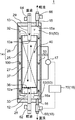
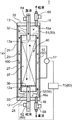
- FIG. 1 shows the overall configuration of a liquid-liquid contact device 1 according to an embodiment of the present invention.
- the liquid-liquid contact device 1 makes a light liquid and a heavy liquid counter-current-contact in order to produce interaction with a light liquid and the heavy liquid whose specific gravity is larger than the light liquid.
- the liquid-liquid contact device 1 causes the extraction of a specific component from one liquid of the light liquid and the heavy liquid to the other liquid as an interaction. That is, the liquid-liquid contact device 1 according to the present embodiment is an extraction device.
- the liquid-liquid contact device 1 is configured so that the light liquid and the heavy liquid after interaction (after the extraction process) can be individually discharged in a state where they are separated from each other.
- the liquid-liquid contact apparatus 1 includes a light liquid introduction pipe 12, a heavy liquid introduction pipe 13, an apparatus main body 14, a liquid level gauge 17, a discharge flow rate control device 18, a light liquid introduction flow rate adjustment valve 62, a heavy liquid.
- An introduction flow rate adjustment valve 64 and a light liquid discharge flow rate adjustment valve 66 are provided.
- the light liquid introduction pipe 12 is a pipe for introducing a light liquid into an inner chamber 40 described later of the apparatus main body 14.
- the heavy liquid introduction pipe 13 is a pipe for introducing heavy liquid into an inner chamber 40 described later of the apparatus main body 14. Specific configurations of the light liquid introduction pipe 12 and the heavy liquid introduction pipe 13 will be described later.
- the apparatus main body 14 is subjected to a process of countercurrently contacting the light liquid and the heavy liquid and a process of separating and separately discharging the light liquid and the heavy liquid after the processing.
- the apparatus main body 14 includes an internal housing 25, an external housing 26, a porous plate 36, and a filler 37.
- the inner casing 25 surrounds the inner chamber 40 that is a space in which the light liquid rising from the lower side and the heavy liquid falling from the upper side are in countercurrent contact.
- the internal housing 25 is a cylindrical body that extends in the vertical direction.
- the internal housing 25 has an upper opening 32 and a lower opening 33 that opens at a position below the upper opening 32. That is, the upper and lower ends of the inner housing 25 are opened, the upper opening of the inner housing 25 is the upper opening 32, and the lower opening of the inner housing 25 is the lower opening 33. is there.
- a light liquid is introduced into the inner chamber 40 from the lower side and a heavy liquid is introduced from the upper side, and the introduced light liquid rises in the inner chamber 40, while the introduced heavy liquid is introduced into the inner chamber 40.
- the light liquid and heavy liquid come into countercurrent contact in the inner chamber 40.
- the light liquid after the countercurrent contact flows out from the upper opening 32 and the heavy liquid after the countercurrent contact flows out from the lower opening 33. That is, the upper opening 32 allows the light liquid after countercurrent contact with the heavy liquid to flow out from the inner chamber 40 through the upper opening 32. Further, the lower opening 33 allows the heavy liquid that has been in countercurrent contact with the light liquid to flow out from the inner chamber 40 through the lower opening 33.
- the outer casing 26 surrounds the inner casing 25 and forms an outer chamber 50 around the inner casing 25.
- the external casing 26 includes a casing body 27, a lower lid 28, an upper lid 29, a light liquid discharge pipe 15, and a heavy liquid discharge pipe 16.
- the housing body 27 is a cylindrical one extending in the vertical direction.
- the casing body 27 has a larger diameter than the inner casing 25 and a length larger than the length of the inner casing 25.
- the casing main body 27 is arranged coaxially with the inner casing 25 and surrounding the inner casing 25. Thereby, a double tube structure is formed.
- the upper end and the lower end of the housing body 27 are open.
- the lower lid 28 is attached to the lower end of the casing body 27 so as to cover and seal the opening at the lower end of the casing body 27.
- the upper lid 29 is attached to the upper end of the casing body 27 so as to cover and seal the opening at the upper end of the casing body 27.
- the light liquid flowing out from the inner chamber 40 through the upper opening 32 of the inner housing 25 and the heavy liquid flowing out from the inner chamber 40 through the lower opening 33 of the inner housing 25 temporarily. It is a space that accumulates.
- the outer chamber 50 the light liquid and the heavy liquid are separated from each other and accumulated due to the difference in specific gravity between them.
- the outer chamber 50 includes an upper space 51, a lower space 52, and a gap region 53.
- the upper space 51 corresponds to a region located above the upper end of the inner casing 25 in the outer chamber 50, that is, a region located above the upper opening 32 of the inner casing 25 in the outer chamber 50.
- the lower space 52 corresponds to a region of the outer chamber 50 located below the lower end of the inner housing 25, that is, a region of the outer chamber 50 located below the lower opening 33 of the inner housing 25.
- the gap region 53 corresponds to a region between the outer peripheral surface of the inner housing 25 and the inner peripheral surface of the outer housing 26 in the outer chamber 50. Light liquid accumulates in approximately the upper half of the upper space 51 and the gap area 53, and heavy liquid accumulates in approximately the lower half of the lower space 52 and the gap area 53. Accordingly, the contact interface 100 between the light liquid and the heavy liquid that accumulates in the outer chamber 50 is formed in the gap region 53.
- the perforated plate 36 is a plate body in which a large number of through holes are formed.
- the porous plate 36 is disposed below the inner chamber 40 so as to be substantially horizontal, and is fixed to the internal housing 25.
- the filling 37 is filled in the inner chamber 40 on the perforated plate 36.
- the filling 37 is for improving the contact efficiency between the light liquid and the heavy liquid that are in countercurrent contact in the inner chamber 40.
- the light liquid introduction pipe 12 is inserted through the lower opening 33 in the lower part of the inner chamber 40 in the inner casing 25.
- the light liquid introduction pipe 12 passes through the lower lid 28 from the lower side of the outer casing 26 and is inserted into the lower portion of the inner chamber 40.
- the light liquid introduction pipe 12 guides the light liquid from the outside of the outer housing 26 to the inner chamber 40.
- the distal end (upper end) of the light liquid introduction pipe 12 is disposed at a position below the porous plate 36 and above the lower opening 33 in the lower part of the inner chamber 40.
- the light liquid introduction pipe 12 has a light liquid discharge port 12 a provided at the tip (upper end) of the light liquid introduction pipe 12.
- the light liquid discharge port 12 a is disposed in the inner chamber 40 at a position below the porous plate 36 and above the lower opening 33.
- the light liquid discharge port 12a allows light liquid guided by the light liquid introduction pipe 12 to be discharged into the inner chamber 40 through the light liquid discharge port 12a. Accordingly, the light liquid is discharged from the light liquid discharge port 12 a at a position above the lower opening 33 in the inner chamber 40.
- the heavy liquid introduction pipe 13 is inserted through the upper opening 32 in the upper part of the inner chamber 40 in the inner housing 25.
- the heavy liquid introduction tube 13 passes through the upper lid 29 from the upper side of the outer casing 26 and is inserted into the upper portion of the inner chamber 40.
- the heavy liquid introduction pipe 13 guides the heavy liquid from the outside of the outer housing 26 to the inner chamber 40.
- the tip (lower end) of the heavy liquid introduction tube 13 is disposed at a position above the region filled with the filling 37 in the upper part of the inner chamber 40 and below the upper opening 32.
- the heavy liquid introduction pipe 13 has a heavy liquid discharge port 13 a provided at the tip (lower end) of the heavy liquid introduction pipe 13.
- the heavy liquid discharge port 13 a is arranged at a position above the region filled with the filling 37 in the inner chamber 40 and below the upper opening 32. That is, the heavy liquid discharge port 13a is disposed in the inner chamber 40 above the light liquid discharge port 12a.
- the heavy liquid discharge port 13a allows the heavy liquid guided by the heavy liquid introduction pipe 13 to be discharged into the inner chamber 40 through the heavy liquid discharge port 13a. Accordingly, heavy liquid is discharged from the heavy liquid discharge port 13 a at a position below the upper opening 32 in the inner chamber 40. In the inner chamber 40, heavy liquid is discharged from the heavy liquid discharge port 13a at a position above the light liquid discharge port 12a.
- the light liquid discharge pipe 15 is a pipe for discharging light liquid from the outer chamber 50.
- the light liquid discharge pipe 15 is attached to the upper lid 29 so as to penetrate the upper lid 29.
- the light liquid discharge pipe 15 has a light liquid discharge port 15a provided at the lower end thereof.
- the light liquid discharge port 15a is a light liquid discharge port of the external housing 26 that allows light liquid to be discharged from the outer chamber 50 through the light liquid discharge port 15a.
- the light liquid discharge port 15a is disposed above a later-described heavy liquid discharge port 16a.
- the light liquid discharge port 15 a is disposed at a position above the upper opening 32 of the internal housing 25, that is, at a position above the upper end of the internal housing 25.
- the light liquid discharge port 15 a is disposed at the upper end portion of the outer chamber 50, that is, the upper end portion of the upper space 51, and is disposed away from the upper opening 32 of the internal housing 25.
- Light liquid is discharged from the upper space 51 of the outer chamber 50 through the light liquid discharge port 15a, flows into the light liquid discharge pipe 15, and passes through the light liquid discharge pipe 15 to the outside of the liquid-liquid contact device 1. It is supposed to be discharged.
- the heavy liquid discharge pipe 16 is a pipe for discharging heavy liquid from the outer chamber 50.
- the heavy liquid discharge pipe 16 is attached to the lower lid 28 so as to penetrate the lower lid 28.
- the heavy liquid discharge pipe 16 has a heavy liquid discharge port 16a provided at the upper end thereof.
- the heavy liquid discharge port 16a is a heavy liquid discharge port of the external housing 26 that allows the heavy liquid to be discharged from the outer chamber 50 through the heavy liquid discharge port 16a.
- the heavy liquid discharge port 16 a is disposed at a position below the lower opening 33 of the internal housing 25, that is, at a position below the lower end of the internal housing 25.
- the heavy liquid discharge port 16 a is disposed at the lower end of the outer chamber 50, that is, the lower end of the lower space 52, and is disposed away from the lower opening 33 of the inner housing 25. Yes. Heavy liquid is discharged from the lower space 52 of the outer chamber 50 through the heavy liquid discharge port 16a, flows into the heavy liquid discharge pipe 16, and passes through the heavy liquid discharge pipe 16 to the outside of the liquid-liquid contact device 1. It is supposed to be discharged.
- the liquid level gauge 17 detects the height position of the contact interface 100 between the light liquid and the heavy liquid in the outer chamber 50. Specifically, the liquid level gauge 17 detects the height position of the contact interface 100 between the light liquid and the heavy liquid formed in the gap region 53. The liquid level meter 17 sequentially outputs the detected height position data of the contact interface 100 to a control unit 70 described later of the discharge flow rate control device 18.
- the discharge flow rate control device 18 controls the discharge flow rate of heavy liquid from the outer chamber 50 through the heavy liquid discharge pipe 16.
- the discharge flow rate control device 18 maintains the height position of the contact interface 100 between the light liquid and the heavy liquid in the outer chamber 50 within a range between the light liquid discharge port 15a and the heavy liquid discharge port 16a.
- the discharge flow rate of heavy liquid from the lower space 52 of the outer chamber 50 through the heavy liquid discharge pipe 16 is controlled.
- the discharge flow rate control device 18 lowers the outer chamber 50 so as to maintain the height position of the contact interface 100 within a range between the upper opening 32 and the lower opening 33 of the inner housing 25.
- a heavy liquid discharge flow rate from the space 52 through the heavy liquid discharge pipe 16 is controlled.
- the discharge flow rate control device 18 controls the discharge flow rate of heavy liquid through the heavy liquid discharge pipe 16 so as to maintain the height position of the contact interface 100 in the vicinity of the center position in the vertical direction of the internal housing 25.
- the discharge flow rate control device 18 includes a heavy liquid discharge flow rate adjustment valve 68 and a control unit 70.
- the heavy liquid discharge flow rate adjustment valve 68 is for adjusting the flow rate of the heavy liquid discharged from the outer chamber 50.
- the heavy liquid discharge flow rate adjustment valve 68 is provided in the heavy liquid discharge pipe 16 and adjusts the flow rate of the heavy liquid flowing through the heavy liquid discharge pipe 16.
- the heavy liquid discharge flow rate adjustment valve 68 increases or decreases the heavy liquid discharge flow rate in accordance with a control signal input from the control unit 70.
- the controller 70 determines the height position of the contact interface 100 according to the height position data of the contact interface 100 between the light liquid and the heavy liquid detected by the level gauge 17 and the light liquid discharge port 15a and the heavy liquid.
- the heavy liquid discharge flow rate adjustment valve 68 is adjusted to adjust the discharge flow rate of the heavy liquid so as to be maintained within the range between the discharge port 16a.
- the control unit 70 stores a predetermined set height position between the light liquid discharge port 15a and the heavy liquid discharge port 16a as a set value of the height position of the contact interface 100.
- the set height position is a height position just between the upper opening 32 and the lower opening 33 of the internal housing 25 and corresponds to the central height position of the internal housing 25 in the vertical direction.
- the controller 70 increases the heavy liquid discharge flow rate to the heavy liquid discharge flow rate adjustment valve 68.
- a control signal to be instructed is sent, whereby the heavy liquid discharge flow rate adjusting valve 68 is increased in the heavy liquid discharge flow rate from the lower space 52 of the outer chamber 50 through the heavy liquid discharge pipe 16. Thereby, the contact interface 100 falls toward the set height position.
- the controller 70 discharges the heavy liquid to the heavy liquid discharge flow rate adjustment valve 68. Is sent to the heavy liquid discharge flow rate adjusting valve 68 to reduce the heavy liquid discharge flow rate from the lower space 52 of the outer chamber 50 through the heavy liquid discharge pipe 16. Thereby, the contact interface 100 rises toward the set height position.
- control unit 70 causes the heavy liquid discharge flow rate adjustment valve 68 to adjust the discharge flow rate of the heavy liquid, so that the height position of the contact interface 100 between the light liquid and the heavy liquid in the outer chamber 50 is the set height position. It is designed to be maintained nearby.
- the light liquid introduction flow rate adjustment valve 62 is provided in the light liquid introduction pipe 12.
- the light liquid introduction flow rate adjustment valve 62 is for adjusting the flow rate of the light liquid introduced into the inner chamber 40 through the light liquid introduction pipe 12.
- the heavy liquid introduction flow rate adjustment valve 64 is provided in the heavy liquid introduction pipe 13.
- the heavy liquid introduction flow rate adjustment valve 64 is for adjusting the flow rate of the heavy liquid introduced into the inner chamber 40 through the heavy liquid introduction pipe 13.
- the light liquid discharge flow rate adjustment valve 66 is provided in the light liquid discharge pipe 15.
- the light liquid discharge flow rate adjustment valve 66 is for adjusting the discharge flow rate of the light liquid discharged from the upper space 51 of the outer chamber 50 through the light liquid discharge pipe 15.
- liquid-liquid contact method according to the present embodiment will be described.
- a specific component is extracted as an interaction between a light liquid and a heavy liquid by bringing the light liquid and the heavy liquid into countercurrent contact in the liquid-liquid contact method.
- the liquid-liquid contact device 1 having the above-described configuration is prepared.
- the light liquid is introduced into the inner chamber 40 through the light liquid introduction pipe 12 and the heavy liquid is introduced into the inner chamber 40 through the heavy liquid introduction pipe 13.
- One liquid of the light liquid and the heavy liquid introduced into the inner chamber 40 contains a specific component to be extracted, and the other liquid of the light liquid and the heavy liquid is changed from the one liquid to the specific component. It is an extractable that can be extracted.
- the light liquid is discharged from the light liquid discharge port 12a at a position below the porous plate 36 in the inner chamber 40, and rises in the inner chamber 40 through a number of holes formed in the porous plate 36.
- the heavy liquid is discharged from the heavy liquid discharge port 13 a at a position above the filling 37 in the inner chamber 40 and descends in the inner chamber 40.
- the light liquid and the heavy liquid are brought into countercurrent contact with each other in the region filled with the filling 37 in the inner chamber 40. By this countercurrent contact, a specific component is extracted from one liquid of the light liquid and the heavy liquid to the other liquid.
- the light liquid after the countercurrent contact rises and flows out from the upper opening 32 to the outer chamber 50, and the heavy liquid after the countercurrent contact descends and passes through a large number of holes in the perforated plate 36 and passes through the lower opening 33. It flows out to the outer chamber 50.
- the light liquid that has flowed into the outer chamber 50 temporarily accumulates in the upper half 51 of the outer chamber 50 and the upper half of the gap region 53 and is discharged from the light liquid discharge port 15a through the light liquid discharge pipe 15. . Further, the heavy liquid that has flowed into the outer chamber 50 is temporarily accumulated in the lower space 52 and the lower half of the gap region 53 of the outer chamber 50, and is discharged from the heavy liquid discharge port 16a through the heavy liquid discharge pipe 16. Is done.
- the light liquid and the heavy liquid temporarily accumulated in the outer chamber 50 form a contact interface 100 between them in the gap region 53.
- the liquid level gauge 17 detects the height position of the contact interface 100 and outputs data of the detected height position to the control unit 70 of the discharge flow rate control device 18.
- the discharge flow rate control device 18 based on the data on the height position of the contact interface 100 detected by the level gauge 17, the contact interface 100 of the light liquid and the heavy liquid formed in the gap region 53 of the outer chamber 50.
- control unit 70 compares the stored set height position of the contact interface with the height position of the contact interface 100 indicated by the data received from the liquid level gauge 17. When the height position of the contact interface 100 indicated by the data received from the liquid level gauge 17 is higher than the set height position, the controller 70 increases the heavy liquid discharge flow rate to the heavy liquid discharge flow rate adjustment valve 68. Send a control signal to indicate On the other hand, when the height position of the contact interface 100 indicated by the data received from the liquid level gauge 17 is lower than the set height position, the controller 70 reduces the heavy liquid discharge flow rate to the heavy liquid discharge flow rate adjustment valve 68. Send a control signal to indicate
- the heavy liquid discharge flow rate adjustment valve 68 When the control signal received from the controller 70 indicates an increase in the heavy liquid discharge flow rate, the heavy liquid discharge flow rate adjustment valve 68 is configured to discharge heavy liquid from the outer chamber 50 through the heavy liquid discharge pipe 16. Increase the discharge flow rate.
- the control signal received from the control unit 70 instructs the heavy liquid discharge flow rate adjustment valve 68 to reduce the heavy liquid discharge flow rate
- the heavy liquid discharge flow rate adjustment valve 68 is connected to the heavy liquid discharge pipe 16 through the heavy liquid discharge pipe 16. Reduce liquid discharge flow rate.
- the height position of the contact interface 100 between the light liquid and the heavy liquid in the outer chamber 50 is light. It is maintained in the vicinity of an intermediate height position between the liquid discharge port 15a and the heavy liquid discharge port 16a, more specifically, in the vicinity of an intermediate height position between the upper opening 32 and the lower opening 33 of the internal housing 25.
- the extraction method using the liquid-liquid contact device 1 according to the present embodiment is performed.
- the light liquid discharge port 15a for discharging the light liquid from the outer chamber 50 is provided above the heavy liquid discharge port 16a for discharging the heavy liquid from the outer chamber 50. For this reason, if the heavy liquid introduced into the inner chamber 40 overflows from the upper opening 32 to the outer chamber 50, the overflowing heavy liquid is not discharged through the light liquid discharge port 15a. The liquid is discharged through the heavy liquid discharge port 16a located below the light liquid discharge port 15a.
- the outer chamber 50 there is usually a light liquid that has flowed into the outer chamber 50 through the upper opening 32, and when heavy liquid overflows from the upper opening 32 to the outer chamber 50 as described above.
- the heavy liquid is mixed in the light liquid in the outer chamber 50.
- the heavy liquid exerts a greater downward force due to gravity than the light liquid, so that the heavy liquid overflowing into the outer chamber 50 descends quickly, while the light liquid falls like the heavy liquid. do not do.
- the light liquid is not discharged from the light liquid discharge port 15a provided on the upper side of the light liquid discharge port 15a and the heavy liquid discharge port 16a, but the light liquid is discharged.
- the heavy liquid discharge port that originally discharges only the heavy liquid. It is possible to prevent the light liquid from being discharged through 16a. As a result, it is possible to prevent the treated heavy liquid and light liquid from being mixed and discharged from the heavy liquid discharge port 16a.
- the light liquid discharge port 15 a is disposed above the upper opening 32 of the internal housing 25. For this reason, even when heavy liquid overflows from the inner chamber 40 to the outer chamber 50 through the upper opening 32, the heavy liquid is more reliably prevented from being discharged through the light liquid discharge port 15a. be able to.
- the heavy liquid discharge port 16 a is disposed below the lower opening 33 of the inner housing 25. For this reason, even when the light liquid overflows from the inner chamber 40 to the outer chamber 50 through the lower opening 33, the light liquid is more reliably discharged through the heavy liquid discharge port 16a. Can be prevented.
- heavy liquid is discharged from the heavy liquid discharge port 13a at a position below the upper opening 32 in the inner chamber 40. For this reason, the heavy liquid discharged from the heavy liquid discharge port 13 a can be reliably introduced into the inner chamber 40.
- light liquid is discharged from the light liquid discharge port 12a at a position above the lower opening 33 in the inner chamber 40. For this reason, the light liquid discharged from the light liquid discharge port 12a can be reliably introduced into the inner chamber 40.
- the discharge flow rate control device 18 sets the height position of the contact interface 100 between the light liquid and the heavy liquid in the outer chamber 50 between the light liquid discharge port 15a and the heavy liquid discharge port 16a.
- the discharge flow rate of the heavy liquid from the outer chamber 50 through the heavy liquid discharge pipe 16 is controlled so as to be maintained within the range. For this reason, when the flow rate of heavy liquid introduced into the inner chamber 40 increases, the contact interface 100 rises and reaches the light liquid discharge port 15a, or when the flow rate of light liquid introduced into the inner chamber 40 increases. It is possible to prevent the interface 100 from being lowered and reaching the heavy liquid discharge port 16a.
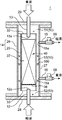
- a liquid-liquid contact device 1 as shown in FIG. 2 was used.
- the basic configuration of the liquid-liquid contact device 1 used in this experiment is the same as the configuration of the liquid-liquid contact device 1 described above.
- the light liquid discharge pipe 15 and the heavy liquid discharge pipe 16 are attached to the housing body 27.
- the light liquid discharge pipe 15 is located below the upper opening 32 at the upper end of the inner housing 25 in the housing body 27 and above the center position in the vertical direction of the housing body 27.
- the heavy liquid discharge pipe 16 is attached to a location above the lower opening 33 of the lower end of the internal housing 25 in the housing body 27 and below the center position in the vertical direction of the housing body 27. It has been.
- the light liquid discharge port 15 a is located below the upper opening 32 and above the center position in the vertical direction of the housing body 27, and the heavy liquid discharge port 16 a is located above the lower opening 33. And it is located below the center position of the up-and-down direction of case body 27.
- the light liquid discharge pipe 15 and the heavy liquid discharge pipe 16 extend horizontally from their attachment locations to the housing body 27 outward in the radial direction of the housing body 27.
- the liquid-liquid contact device 1 used in this experiment does not include the light liquid introduction flow rate adjustment valve and the heavy liquid introduction flow rate adjustment valve, and the heavy liquid discharge flow rate adjustment valve 68 to adjust the discharge flow rate of the heavy liquid. There is also no control unit for controlling the above.
- a pipe made of vinyl chloride having an inner diameter of 103 mm, an outer diameter of 114 mm, and a vertical length of 800 mm is used as the casing body 27.
- the inner casing 25 a pipe made of vinyl chloride having an inner diameter of 71 mm, an outer diameter of 76 mm, and a vertical length of 600 mm is used.
- Each leg 25a is composed of a plate-shaped piece having a vertical length of 200 mm, a thickness of 5 mm, and a width of 15 mm in the radial direction of the internal housing 25.
- the four legs 25 a are arranged at equal intervals in the circumferential direction of the internal housing 25.
- Each leg 25a is attached to the internal housing 25 so as to protrude 100 mm downward from the lower end of the internal housing 25 and protrude 10 mm radially inward from the inner wall surface of the internal housing 25.
- porous plate 36 installed in the lower part of the inner chamber 40, it is a circular plate formed of PEEK (polyether ether ketone) or PVC (polyvinyl chloride), and has a large number of through-holes having a diameter of 10 mm. Those arranged in a staggered pattern were used.
- PEEK polyether ether ketone
- PVC polyvinyl chloride
- the Raschig ring is cylindrical and has a length and an outer diameter of 12 mm in the central axis direction and a thickness of 2 mm.
- a level sensor having a probe was used as an interface meter for detecting the height position of the contact interface 100 between the light liquid and the heavy liquid in the outer chamber 50.
- the probe is a detection unit that detects the position of the contact interface 100, and generally has a length over a distance from the upper lid 29 to the vicinity of the lower end of the inner housing 25.
- the probe is inserted in the gap region 53 of the outer chamber 50 to a position near the lower end of the inner housing 25 through the upper lid 29 in a vertically extending posture, and the level sensor is fixed to the outer housing 26 in this state. .
- liquid-liquid contact device 1 Using the liquid-liquid contact device 1 as described above, heavy liquid is introduced into the inner chamber 40 through the heavy liquid introduction pipe 13 at a flow rate of 30 L / h, and light liquid is introduced into the inner chamber 40 through the light liquid introduction pipe 12. Introduced at a flow rate of h.
- the heavy liquid water containing metal ions was used.
- a light liquid a metal extractant PC-88A manufactured by Daihachi Chemical Industry Co., Ltd. diluted with kerosene to 1 mol / L was used.
- PC-88A is mainly composed of 2-ethylhexylphosphonic acid mono-2-ethylhexyl ester.
- the heavy liquid descends from the upper part in the inner chamber 40, while the light liquid rises from the lower part in the inner chamber 40. It was confirmed that the light and heavy liquids were in countercurrent contact. In addition, a light liquid that flows out from the inner chamber 40 to the outer chamber 50 through the upper opening 32 after the countercurrent contact, and a heavy liquid that flows out from the inner chamber 40 to the outer chamber 50 through the lower opening 33 after the countercurrent contact. However, it was confirmed that the contact interface 100 was formed at a height position between the light liquid discharge port 15a and the heavy liquid discharge port 16a in the gap region 53 of the outer chamber 50.
- liquid-liquid contact apparatus by this invention is not necessarily limited to the thing like the said embodiment.
- the liquid-liquid contact device according to the present invention for example, the following configuration can be adopted.
- the light liquid discharge pipe 15 does not necessarily have to be attached to the upper cover 29 of the outer casing 26, and the heavy liquid discharge pipe 16 does not necessarily have to be attached to the lower cover 28 of the outer casing 26. That is, the light liquid discharge pipe 15 and the heavy liquid discharge pipe 16 may be attached to the housing body 27 as in the liquid-liquid contact apparatus 1 used in the above-described experiment. However, the light liquid discharge pipe 15 and the heavy liquid discharge pipe 16 are attached to the casing main body 27 in the liquid liquid contact device 1 used in the above-described experiment. It is not limited to the part attached to 27. FIG.
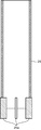
- FIG. 5 shows a first modification in which an attachment location different from the case of the liquid-liquid contact device 1 used in the above-described experiment is adopted as an attachment location of the light liquid discharge pipe 15 and the heavy liquid discharge pipe 16 with respect to the housing body 27. A liquid-liquid contact device 1 is shown.
- the light liquid discharge pipe 15 is attached to a portion of the housing main body 27 that is located above the upper opening 32 at the upper end of the internal housing 25, and
- the liquid discharge pipe 16 is attached to a portion of the housing body 27 that is located below the lower opening 33 of the lower end of the internal housing 25.
- the light liquid discharge pipe 15 is attached to the side wall of the upper end portion of the housing main body 27, and the heavy liquid discharge pipe 16 is attached to the side wall of the lower end portion of the housing main body 27.
- the light liquid discharge pipe 15 extends horizontally from a location where the light liquid discharge pipe 15 is attached to the casing body 27 outward in the radial direction of the casing body 27. Further, the heavy liquid discharge pipe 16 extends horizontally from a position where the heavy liquid discharge pipe 16 is attached to the housing body 27 outward in the radial direction of the housing body 27.
- the light liquid discharge port 15 a is positioned above the upper opening 32 at the upper end of the internal housing 25, and the heavy liquid discharge port 16 a is positioned below the lower opening 33 at the lower end of the internal housing 25. Yes.
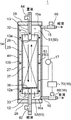
- FIG. 6 shows a liquid-liquid contact device 1 according to a second modification including such a discharge flow rate control device 18.
- the discharge flow rate control device 18 includes a light liquid discharge flow rate adjustment valve 66 and a control unit 70.
- the light liquid discharge flow rate adjustment valve 66 is provided in the light liquid discharge pipe 15.
- the light liquid discharge flow rate adjusting valve 66 discharges light liquid discharged from the upper space 51 of the outer chamber 50 through the light liquid discharge pipe 15, that is, discharged from the upper space 51 of the outer chamber 50 through the light liquid discharge port 15a.
- the discharge flow rate of the light liquid is adjusted according to a control signal from the control unit 70.
- the controller 70 determines the height position of the contact interface 100 according to the height position data of the contact interface 100 between the light liquid and the heavy liquid detected by the level gauge 17 and the light liquid discharge port 15a and the heavy liquid.
- the light liquid discharge flow rate adjustment valve 66 is caused to adjust the light liquid discharge flow rate from the upper space 51 of the outer chamber 50 so as to be maintained within the range between the discharge port 16a.
- the control unit 70 stores the set height position of the contact interface 100 as in the case of the above embodiment.
- the control unit 70 reduces the light liquid discharge flow rate to the light liquid discharge flow rate adjustment valve 66.
- An instructing control signal is sent, and thereby the light liquid discharge flow rate adjustment valve 66 is reduced in the light liquid discharge flow rate from the upper space 51 of the outer chamber 50. Thereby, the contact interface 100 falls toward the set height position.
- the control unit 70 determines the light liquid discharge flow rate to the light liquid discharge flow rate adjustment valve 66.
- a control signal for instructing the increase is sent, whereby the light liquid discharge flow rate adjusting valve 66 is caused to increase the light liquid discharge flow rate from the upper space 51 of the outer chamber 50.
- the contact interface 100 rises toward the set height position.
- control unit 70 causes the light liquid discharge flow rate adjustment valve 66 to adjust the light liquid discharge flow rate so that the height position of the contact interface 100 formed in the outer chamber 50 is the light liquid discharge port 15a and the heavy liquid. It is maintained in the vicinity of a set height position with respect to the discharge port 16 a, specifically, in the vicinity of a height position just between the upper opening 32 and the lower opening 33 of the internal housing 25.
- the liquid-liquid contact device 1 maintains the height position of the contact interface 100 between the light liquid and the heavy liquid formed in the outer chamber 50 within the range between the light liquid discharge port 15a and the heavy liquid discharge port 16a.
- an introduction flow rate control device 80 that controls the flow rate of heavy liquid introduced into the inner chamber 40 through the heavy liquid introduction pipe 13 may be provided.
- FIG. 7 shows a liquid-liquid contact device 1 according to a third modification including such an introduction flow rate control device 80.
- the introduction flow rate control device 80 sets the height position of the contact interface 100 between the light liquid and the heavy liquid formed in the outer chamber 50 to the light liquid discharge port 15a and the heavy liquid.
- the flow rate of heavy liquid introduced into the inner chamber 40 through the heavy liquid introduction pipe 13 is controlled so as to be maintained within the range between the outlet 16a.
- the introduction flow rate control device 80 directly controls the flow rate of heavy liquid passing through the heavy liquid introduction pipe 13, that is, the discharge flow rate of heavy liquid discharged from the heavy liquid discharge port 13a.
- the introduction flow rate control device 80 includes a heavy liquid introduction flow rate adjustment valve 64 and a control unit 70.
- the heavy liquid introduction flow rate adjustment valve 64 is provided in the heavy liquid introduction pipe 13, and an introduction flow rate of heavy liquid introduced into the inner chamber 40 through the heavy liquid introduction pipe 13 (a flow of heavy liquid from the heavy liquid discharge port 13a).
- the discharge flow rate) is adjusted according to a control signal from the control unit 70.
- the controller 70 determines the height position of the contact interface 100 according to the height position data of the contact interface 100 between the light liquid and the heavy liquid detected by the level gauge 17 and the light liquid discharge port 15a and the heavy liquid.
- the heavy liquid introduction flow rate adjusting valve 64 is adjusted so that the heavy liquid introduction flow rate into the inner chamber 40 (the discharge flow rate of heavy liquid from the heavy liquid discharge port 13a) is maintained within the range between the discharge port 16a.
- the control unit 70 stores the set height position of the contact interface 100 as in the case of the above embodiment.
- the control unit 70 reduces the heavy liquid introduction flow rate to the heavy liquid introduction flow rate adjustment valve 64.
- a control signal for instructing is sent, and thereby the heavy liquid introduction flow rate adjusting valve 64 is reduced in the heavy liquid introduction flow rate into the inner chamber 40.
- the flow rate of the heavy liquid flowing out from the inner chamber 40 through the lower opening 33 to the outer chamber 50 is reduced, and as a result, the contact interface 100 is lowered toward the set height position.
- the control unit 70 determines the introduction flow rate of the heavy liquid to the heavy liquid introduction flow rate adjustment valve 64.
- a control signal for instructing the increase is sent, whereby the flow rate of heavy liquid introduction into the inner chamber 40 is increased in the heavy liquid introduction flow rate adjustment valve 64.
- the flow rate of the heavy liquid flowing out from the inner chamber 40 through the lower opening 33 to the outer chamber 50 increases, and as a result, the contact interface 100 rises toward the set height position.
- control unit 70 causes the heavy liquid introduction flow rate adjustment valve 64 to adjust the heavy liquid introduction flow rate so that the height position of the contact interface 100 formed in the outer chamber 50 is the light liquid discharge port 15a and the heavy liquid. It is maintained in the vicinity of a set height position with respect to the discharge port 16 a, specifically, in the vicinity of a height position just between the upper opening 32 and the lower opening 33 of the internal housing 25.
- the introduction flow rate control device 80 maintains the height position of the contact interface 100 between the light liquid and the heavy liquid formed in the outer chamber 50 within the range between the light liquid discharge port 15a and the heavy liquid discharge port 16a. As described above, the flow rate of the light liquid introduced into the inner chamber 40 through the light liquid introduction pipe 12 may be controlled.
- FIG. 8 shows a liquid-liquid contact device 1 according to a fourth modification including such an introduction flow rate control device 80.
- the introduction flow rate control device 80 directly controls the light liquid flow rate through the light liquid introduction pipe 12, that is, the light liquid discharged from the light liquid discharge port 12a. It controls the discharge flow rate.
- the introduction flow rate control device 80 in the fourth modification has a light liquid introduction flow rate adjustment valve 62 and a control unit 70.
- the light liquid introduction flow rate adjustment valve 62 is provided in the light liquid introduction pipe 12, and an introduction flow rate of light liquid introduced into the inner chamber 40 through the light liquid introduction pipe 12 (the light liquid from the light liquid discharge port 12a).
- the discharge flow rate is adjusted according to a control signal from the control unit 70.
- the controller 70 determines the height position of the contact interface 100 according to the height position data of the contact interface 100 between the light liquid and the heavy liquid detected by the level gauge 17 and the light liquid discharge port 15a and the heavy liquid.
- the light liquid introduction flow rate adjustment valve 62 adjusts the light liquid introduction flow rate into the inner chamber 40 (light liquid discharge flow rate from the light liquid discharge port 12a) so as to maintain the range between the discharge port 16a.
- the control unit 70 stores the set height position of the contact interface 100 as in the case of the above embodiment.
- the controller 70 increases the light liquid introduction flow rate to the light liquid introduction flow rate adjustment valve 62.
- a control signal for instructing is sent, whereby the light liquid introduction flow rate adjustment valve 62 is increased in the light liquid introduction flow rate into the inner chamber 40.
- the flow rate of the light liquid flowing out from the inner chamber 40 through the upper opening 32 to the outer chamber 50 increases, and as a result, the contact interface 100 decreases toward the set height position.
- the control unit 70 determines the light liquid introduction flow rate to the light liquid introduction flow rate adjustment valve 62.
- a control signal for instructing the reduction is sent, whereby the light liquid introduction flow rate adjusting valve 62 is reduced in the light liquid introduction flow rate into the inner chamber 40.
- the flow rate of the light liquid flowing out from the inner chamber 40 through the upper opening 32 to the outer chamber 50 is reduced, and as a result, the contact interface 100 rises toward the set height position.
- control unit 70 causes the light liquid introduction flow rate adjustment valve 62 to adjust the light liquid introduction flow rate, so that the height position of the contact interface 100 formed in the outer chamber 50 corresponds to the light liquid discharge port 15a and the heavy liquid. It is maintained in the vicinity of a set height position with respect to the discharge port 16 a, specifically, in the vicinity of a height position just between the upper opening 32 and the lower opening 33 of the internal housing 25.
- liquid-liquid contact device does not necessarily include the discharge flow rate control device and the introduction flow rate control device.
- emission for maintaining the height position of the contact interface 100 of the light liquid and heavy liquid formed in the outer chamber 50 in the range between the light liquid discharge port 15a and the heavy liquid discharge port 16a.
- Adjustment of heavy liquid discharge flow rate by the flow rate adjustment valve 68, adjustment of light liquid discharge flow rate by the light liquid discharge flow rate adjustment valve 66, adjustment of heavy liquid introduction flow rate by the heavy liquid introduction flow rate adjustment valve 64, and light liquid introduction The adjustment of the light liquid introduction flow rate by the flow rate adjustment valve 62 is not necessarily performed by the control unit 70 automatically controlling each adjustment valve according to the height position data of the contact interface 100 detected by the level gauge 17. Therefore, the control valve is not limited to those which are performed by the control valve.
- Adjustment and adjustment of the flow rate of the light liquid introduced into the inner chamber 40 are performed so that the height position of the contact interface 100 formed in the outer chamber 50 is between the light liquid discharge port 15a and the heavy liquid discharge port 16a. It may be maintained within the range.
- the heavy liquid discharge flow rate from the outer chamber may be controlled without using the heavy liquid discharge flow rate adjustment valve, and the light liquid discharge flow rate from the outer chamber may be controlled without using the light liquid discharge flow rate adjustment valve. May be.
- the flow rate of heavy liquid introduced into the inner chamber may be controlled without using the heavy liquid introduction flow rate adjustment valve, and the light and light introduction flow rate into the inner chamber may be controlled without using the light liquid introduction flow rate adjustment valve. Also good.
- the discharge flow rate control device 18 controls both the discharge flow rate of the light liquid from the outer chamber 50 and the discharge flow rate of the heavy liquid, and sets the height position of the contact interface 100 to the light liquid discharge port 15a and the heavy liquid discharge port 16a. It may be maintained within a range between.
- the control unit 70 sends a control signal to the light liquid discharge flow rate adjustment valve 66 to cause the light liquid discharge flow rate adjustment valve 66 to adjust the light liquid discharge flow rate, and the heavy liquid discharge flow rate adjustment valve.
- a control signal may be sent to 68 to cause the heavy liquid discharge flow rate adjustment valve 68 to adjust the heavy liquid discharge flow rate.
- the introduction flow rate control device 80 controls both the introduction flow rate of the light liquid into the inner chamber 40 and the introduction flow rate of the heavy liquid, and sets the height position of the contact interface 100 to the light liquid discharge port 15a and the heavy liquid discharge port 16a. It may be maintained within a range between.
- the control unit 70 sends a control signal to the light liquid introduction flow rate adjustment valve 62 to cause the light liquid introduction flow rate adjustment valve 62 to adjust the light liquid introduction flow rate into the inner chamber 40 and A control signal may be sent to the liquid introduction flow rate adjustment valve 64 so that the heavy liquid introduction flow rate adjustment valve 64 adjusts the introduction flow rate of heavy liquid into the inner chamber 40.
- the inner casing is not necessarily a cylinder
- the casing main body of the outer casing is not necessarily a cylinder
- the upper opening is not necessarily provided at the upper end of the inner casing, and the lower opening is not necessarily provided at the lower end of the inner casing. That is, as long as the lower opening is disposed below the upper opening, the upper opening may be provided at a location other than the upper end of the inner casing, and the lower opening is other than the lower end of the inner casing. It may be provided at the location.
- the light liquid discharge port is not necessarily limited to that provided in the light liquid discharge pipe.
- the light liquid discharge port may be formed in the upper lid of the external housing or the housing body.
- the heavy liquid discharge port is not necessarily limited to that provided in the heavy liquid discharge pipe.
- the heavy liquid discharge port may be formed in the lower lid of the external housing or the housing body.
- the heavy liquid discharge port may be disposed above the lower opening of the internal housing.
- the light liquid discharge port may be disposed below the upper opening of the internal housing.
- the interaction that occurs in the light liquid and the heavy liquid by bringing the light liquid and the heavy liquid into countercurrent contact is not limited to extraction.
- the interaction generated in the light liquid and the heavy liquid by the countercurrent contact between the light liquid and the heavy liquid may be a chemical reaction between the light liquid and the heavy liquid.
- the light liquid introduction pipe is not necessarily limited to the one that introduces the light liquid to a position above the lower opening of the inner casing in the inner chamber.
- the light liquid introduction pipe may be configured to introduce the light liquid to a position outside the inner chamber and below the lower opening (a position directly below). That is, the light liquid discharge port may be disposed at a position below the lower opening of the internal housing (a position immediately below). In this configuration, the light liquid discharged from the light liquid discharge port rises and flows into the inner chamber through the lower opening.
- the heavy liquid introduction pipe is not necessarily limited to the one that introduces the heavy liquid to a position below the upper opening of the inner housing in the inner chamber.
- the heavy liquid introduction tube may be configured to introduce heavy liquid to a position outside the inner chamber and above the upper opening (a position immediately above). That is, the heavy liquid discharge port may be arranged at a position above (above) the upper opening of the internal housing. In this configuration, the heavy liquid discharged from the heavy liquid discharge port descends and flows into the inner chamber through the upper opening.
- the liquid-liquid contact device is a liquid-liquid contact device that counter-contacts a light liquid and a heavy liquid having a specific gravity larger than that of the light liquid, and extends in the vertical direction from the lower side.
- An inner housing surrounding the inner chamber for countercurrent contact between the rising light liquid and the heavy liquid descending from the upper side, and the inner housing so as to form an outer chamber around the inner housing
- An outer casing surrounding the outer casing, a light liquid introduction pipe for guiding the light liquid from the outside of the outer casing to the inner chamber, and a heavy liquid introduction pipe for guiding the heavy liquid from the outside of the outer casing to the inner chamber;
- the light liquid introduction pipe is a light liquid discharge port disposed in the inner chamber, and the light liquid guided by the light liquid introduction pipe is discharged into the inner chamber through the light liquid discharge port.
- the heavy liquid introduction pipe is located above the light liquid discharge port in the inner chamber.
- a heavy liquid discharge port disposed to allow the heavy liquid guided by the heavy liquid introduction pipe to be discharged into the inner chamber through the heavy liquid discharge port; Is an upper opening that allows the light liquid after countercurrent contact with the heavy liquid to flow from the inner chamber through the upper opening to the outer chamber, and below the upper opening.
- a lower opening that is open at a position that allows the heavy liquid after countercurrent contact with the light liquid to flow from the inner chamber through the lower opening to the outer chamber;
- the external housing is a heavy liquid discharge port that allows the heavy liquid to be discharged from the outer chamber through the heavy liquid discharge port, and from the heavy liquid discharge port.
- a light liquid discharge port arranged on the top, which allows the light liquid to be discharged from the outer chamber through the light liquid discharge port. I have a thing, a.
- the light liquid discharge port of the external housing that discharges light liquid from the outer chamber is provided above the heavy liquid discharge port of the external housing that discharges heavy liquid from the outer chamber.
- the overflowing heavy liquid is not discharged through the light liquid discharge port, but below the light liquid discharge port. It is discharged through the located heavy liquid outlet.
- the outer chamber there is usually a light liquid that flows out to the outer chamber through the upper opening, and when heavy liquid overflows from the upper opening to the outer chamber as described above, Heavy liquid will be mixed in light liquid.
- the heavy liquid exerts a greater downward force due to gravity than the light liquid, so the heavy liquid overflowing into the outer chamber descends quickly, while the light liquid does not fall like the heavy liquid. .
- the heavy liquid discharge port provided on the upper side of the light liquid discharge port and the heavy liquid discharge port the heavy liquid that descends quickly is not discharged and the light liquid is discharged.
- the heavy liquid discharge port provided on the lower side of the heavy liquid discharge port the light liquid that does not fall like the heavy liquid is not discharged, and the heavy liquid is discharged.
- this liquid-liquid contact device even when the heavy liquid introduced into the inner chamber overflows from the upper opening of the inner chamber to the outer chamber, it passes through the light liquid discharge port that originally discharges only the light liquid.
- the heavy liquid can be prevented from being discharged, and the processed light liquid and heavy liquid can be prevented from being mixed and discharged from the light liquid discharge port.
- the liquid-liquid contact device even when light liquid introduced into the inner chamber overflows from the lower opening of the inner chamber to the outer chamber, the liquid-liquid contact device passes through a heavy liquid discharge port that originally discharges only heavy liquid.
- the light liquid can be prevented from being discharged, and the processed heavy liquid and the light liquid can be prevented from being mixed and discharged from the heavy liquid discharge port.
- the light liquid discharge port is disposed above the upper opening.
- the heavy liquid discharge port is preferably disposed below the lower opening.
- the heavy liquid discharge port is preferably disposed below the upper opening in the inner chamber.
- the heavy liquid discharged from the heavy liquid discharge port of the heavy liquid introduction pipe can be reliably introduced into the inner chamber.
- the light liquid discharge port is disposed above the lower opening in the inner chamber.
- the liquid-liquid contact device maintains a height position of a contact interface between the light liquid and the heavy liquid formed in the outer chamber within a range between the light liquid discharge port and the heavy liquid discharge port.
- a discharge flow rate control device for controlling at least one of the discharge flow rate of the light liquid from the outer chamber through the light liquid discharge port and the discharge flow rate of the heavy liquid from the outer chamber through the heavy liquid discharge port. It is preferable to further provide.
- At least one of the discharge flow rate of light liquid from the outer chamber through the light liquid discharge port and the discharge flow rate of heavy liquid from the outer chamber through the heavy liquid discharge port is controlled by the discharge flow rate control device. Accordingly, the height position of the contact interface between the light liquid and the heavy liquid in the outer chamber is maintained within the range between the light liquid discharge port and the heavy liquid discharge port. For this reason, when the flow rate of heavy liquid introduced into the inner chamber increases, the contact interface rises to reach the light liquid discharge port, or when the flow rate of light liquid introduced into the inner chamber increases, the contact interface It is possible to prevent the drop from reaching the heavy liquid discharge port. For this reason, along with fluctuations in the flow rate of heavy and light liquids into the inner chamber, heavy liquid is discharged from the outer chamber through the light liquid discharge port, and light liquid from the outer chamber passes through the heavy liquid discharge port. Can be prevented.
- the liquid-liquid contact device maintains a height position of a contact interface between the light liquid and the heavy liquid formed in the outer chamber within a range between the light liquid discharge port and the heavy liquid discharge port.
- An introduction flow rate control device for controlling at least one of the introduction flow rate of the light liquid into the inner chamber through the light liquid introduction pipe and the introduction flow rate of the heavy liquid into the inner chamber through the heavy liquid introduction pipe, It is preferable to further provide.
- the introduction flow rate of the light liquid into the inner chamber through the light liquid introduction pipe and the introduction flow rate of the heavy liquid into the inner chamber through the heavy liquid introduction pipe is controlled by the introduction flow control device. Accordingly, the height position of the contact interface between the light liquid and the heavy liquid in the outer chamber is maintained within the range between the light liquid discharge port and the heavy liquid discharge port. For this reason, the introduction flow rate of light liquid into the inner chamber increases until the contact interface decreases and reaches the heavy liquid discharge port, or the heavy liquid introduction flow rate until the contact interface rises and reaches the light liquid discharge port. Can be prevented from increasing. Therefore, in this configuration, the heavy liquid and the heavy liquid are discharged from the outer chamber through the light liquid discharge port, or the light liquid and the heavy liquid are discharged from the outer chamber through the heavy liquid discharge port. Variations in the flow rate of the liquid can be prevented.
- the liquid-liquid contact method according to the embodiment and the modified example is a liquid-liquid contact method in which a light liquid and a heavy liquid having a specific gravity larger than that of the light liquid are in countercurrent contact, and the liquid-liquid contact device is prepared. Introducing the light liquid into the inner chamber through the light liquid introduction pipe and introducing the heavy liquid into the inner chamber through the heavy liquid introduction pipe; and the light liquid introduced into the inner chamber The heavy liquid introduced into the inner chamber ascends and descends, so that the light liquid and the heavy liquid come into countercurrent contact, and after the contact process, the light liquid is removed from the inner chamber to the upper side.
- a discharge step of discharging from the outer chamber through the heavy liquid discharge port Through the light liquid outlet, the height position of the contact interface between the light liquid and the heavy liquid formed in the outer chamber is maintained within the range between the light liquid outlet and the heavy liquid outlet.
- a discharge flow rate control step for controlling at least one of the discharge flow rate of the light liquid from the outer chamber and the discharge flow rate of the heavy liquid from the outer chamber through the heavy liquid discharge port.
- this liquid-liquid contact method by controlling at least one of a light liquid discharge flow rate from the outer chamber through the light liquid discharge port and a heavy liquid discharge flow rate from the outer chamber through the heavy liquid discharge port, The height position of the contact interface between the light liquid and the heavy liquid in the outer chamber is maintained within the range between the light liquid discharge port and the heavy liquid discharge port. For this reason, when the flow rate of heavy liquid introduced into the inner chamber increases, the contact interface rises to reach the light liquid discharge port, or when the flow rate of light liquid introduced into the inner chamber increases, the contact interface It is possible to prevent the drop from reaching the heavy liquid discharge port. For this reason, along with fluctuations in the flow rate of heavy and light liquids into the inner chamber, heavy liquid is discharged from the outer chamber through the light liquid discharge port, and light liquid from the outer chamber passes through the heavy liquid discharge port. Can be prevented.
- the liquid-liquid contact method is a liquid-liquid contact method in which a light liquid and a heavy liquid having a specific gravity larger than that of the light liquid are counter-current contacted, and the liquid-liquid contact device is prepared.
- the light liquid and the heavy liquid come into countercurrent contact with each other, and after the contact process, the light liquid is removed from the inner chamber.
- a discharge step of discharging from the outer chamber through the heavy liquid discharge port The light liquid introduction is performed so that the height position of the contact interface between the light liquid and the heavy liquid formed in the outer chamber is maintained within a range between the light liquid discharge port and the heavy liquid discharge port.
- this liquid-liquid contact method by controlling at least one of a light liquid introduction flow rate into the inner chamber through the light liquid introduction tube and a heavy liquid introduction flow rate into the inner chamber through the heavy liquid introduction tube, The height position of the contact interface between the light liquid and the heavy liquid in the outer chamber is maintained within the range between the light liquid discharge port and the heavy liquid discharge port. For this reason, the introduction flow rate of light liquid into the inner chamber increases until the contact interface decreases and reaches the heavy liquid discharge port, or the heavy liquid introduction flow rate until the contact interface rises and reaches the light liquid discharge port. Can be prevented from increasing.
- the heavy liquid is discharged from the outer chamber through the light liquid discharge port, or the light liquid is discharged from the outer chamber to the inner chamber through which the light liquid is discharged through the heavy liquid discharge port. It is possible to prevent fluctuations in the introduction flow rate of liquid and heavy liquid.
- the embodiment and the modified example even when the heavy liquid introduced into the inner chamber overflows from the upper opening, the light liquid and the heavy liquid after the treatment are separated from the liquid liquid contact device. It is possible to prevent the liquid from being mixed and discharged.
Landscapes
- Chemical & Material Sciences (AREA)
- Chemical Kinetics & Catalysis (AREA)
- Extraction Or Liquid Replacement (AREA)
- Production Of Liquid Hydrocarbon Mixture For Refining Petroleum (AREA)
- Automatic Analysis And Handling Materials Therefor (AREA)
Abstract
Description
前記実施形態及び前記変形例をまとめると、以下の通りである。
Claims (9)
- 軽液とその軽液よりも比重が大きい重液とを向流接触させる液液接触装置であって、
上下方向に延びていて下側から上昇する前記軽液と上側から降下する前記重液とを向流接触させるための内室の周りを囲む内部筐体と、
前記内部筐体の周りに外室を形成するように前記内部筐体を囲む外部筐体と、
前記外部筐体の外部から前記内室へ前記軽液を導く軽液導入管と、
前記外部筐体の外部から前記内室へ前記重液を導く重液導入管と、を備え、
前記軽液導入管は、前記内室に配置された軽液吐出口であって前記軽液導入管によって導かれる前記軽液が当該軽液吐出口を通って前記内室に吐出されるのを許容するものを有し、
前記重液導入管は、前記内室において前記軽液吐出口よりも上に配置された重液吐出口であって前記重液導入管によって導かれる前記重液が当該重液吐出口を通って前記内室に吐出されるのを許容するものを有し、
前記内部筐体は、上側開口であって前記重液と向流接触した後の前記軽液が前記内室から当該上側開口を通って前記外室へ流出するのを許容するものと、前記上側開口よりも下の位置で開口している下側開口であって前記軽液と向流接触した後の前記重液が前記内室から当該下側開口を通って前記外室へ流出するのを許容するものと、を有し、
前記外部筐体は、重液排出口であって前記外室から当該重液排出口を通って前記重液が排出されるのを許容するものと、前記重液排出口よりも上に配置された軽液排出口であって前記外室から当該軽液排出口を通って前記軽液が排出されるのを許容するものと、を有する、液液接触装置。 - 請求項1に記載の液液接触装置において、
前記軽液排出口は、前記上側開口よりも上に配置されている、液液接触装置。 - 請求項1に記載の液液接触装置において、
前記重液排出口は、前記下側開口よりも下に配置されている、液液接触装置。 - 請求項1に記載の液液接触装置において、
前記重液吐出口は、前記内室において前記上側開口よりも下に配置されている、液液接触装置。 - 請求項1に記載の液液接触装置において、
前記軽液吐出口は、前記内室において前記下側開口よりも上に配置されている、液液接触装置。 - 請求項1に記載の液液接触装置において、
前記外室において形成される前記軽液と前記重液との接触界面の高さ位置を前記軽液排出口と前記重液排出口との間の範囲内に維持するように前記軽液排出口を通じた前記外室からの前記軽液の排出流量及び前記重液排出口を通じた前記外室からの前記重液の排出流量の少なくとも一方を制御する排出流量制御装置をさらに備える、液液接触装置。 - 請求項1に記載の液液接触装置において、
前記外室において形成される前記軽液と前記重液との接触界面の高さ位置を前記軽液排出口と前記重液排出口との間の範囲内に維持するように前記軽液導入管を通じた前記内室への前記軽液の導入流量及び前記重液導入管を通じた前記内室への前記重液の導入流量の少なくとも一方を制御する導入流量制御装置をさらに備える、液液接触装置。 - 軽液とその軽液よりも比重が大きい重液とを向流接触させる液液接触方法であって、
請求項1~7のいずれか1項に記載の液液接触装置を用意する用意工程と、
前記軽液導入管を通じて前記内室へ前記軽液を導入するとともに前記重液導入管を通じて前記内室へ前記重液を導入する導入工程と、
前記内室に導入した前記軽液が上昇するとともに前記内室に導入した前記重液が降下することにより、それらの軽液と重液が向流接触する接触工程と、
前記接触工程の後、前記軽液が前記内室から前記上側開口を通って前記外室へ流出し、その外室から前記軽液排出口を通って排出される一方、前記重液が前記内室から前記下側開口を通って前記外室へ流出し、その外室から前記重液排出口を通って排出される排出工程と、
前記外室において形成される前記軽液と前記重液との接触界面の高さ位置を前記軽液排出口と前記重液排出口との間の範囲内に維持するように前記軽液排出口を通じた前記外室からの前記軽液の排出流量及び前記重液排出口を通じた前記外室からの前記重液の排出流量の少なくとも一方を制御する排出流量制御工程と、を備える、液液接触方法。 - 軽液とその軽液よりも比重が大きい重液とを向流接触させる液液接触方法であって、
請求項1~7のいずれか1項に記載の液液接触装置を用意する用意工程と、
前記軽液導入管を通じて前記内室へ前記軽液を導入するとともに前記重液導入管を通じて前記内室へ前記重液を導入する導入工程と、
前記内室に導入した前記軽液が上昇するとともに前記内室に導入した前記重液が降下することにより、それらの軽液と重液が向流接触する接触工程と、
前記接触工程の後、前記軽液が前記内室から前記上側開口を通って前記外室へ流出し、その外室から前記軽液排出口を通って排出される一方、前記重液が前記内室から前記下側開口を通って前記外室へ流出し、その外室から前記重液排出口を通って排出される排出工程と、
前記外室において形成される前記軽液と前記重液との接触界面の高さ位置を前記軽液排出口と前記重液排出口との間の範囲内に維持するように前記軽液導入管を通じた前記内室への前記軽液の導入流量及び前記重液導入管を通じた前記内室への前記重液の導入流量の少なくとも一方を制御する導入流量制御工程と、を備える、液液接触方法。
Priority Applications (3)
| Application Number | Priority Date | Filing Date | Title |
|---|---|---|---|
| US16/079,026 US10561963B2 (en) | 2016-02-24 | 2017-02-03 | Liquid-liquid contact device and liquid-liquid contact method |
| KR1020187025860A KR102106946B1 (ko) | 2016-02-24 | 2017-02-03 | 액액 접촉 장치 및 액액 접촉 방법 |
| CN201780012603.5A CN108697949A (zh) | 2016-02-24 | 2017-02-03 | 液液接触装置及液液接触方法 |
Applications Claiming Priority (2)
| Application Number | Priority Date | Filing Date | Title |
|---|---|---|---|
| JP2016032984A JP6623080B2 (ja) | 2016-02-24 | 2016-02-24 | 液液接触装置及び液液接触方法 |
| JP2016-032984 | 2016-02-24 |
Publications (1)
| Publication Number | Publication Date |
|---|---|
| WO2017145702A1 true WO2017145702A1 (ja) | 2017-08-31 |
Family
ID=59685299
Family Applications (1)
| Application Number | Title | Priority Date | Filing Date |
|---|---|---|---|
| PCT/JP2017/003951 Ceased WO2017145702A1 (ja) | 2016-02-24 | 2017-02-03 | 液液接触装置及び液液接触方法 |
Country Status (5)
| Country | Link |
|---|---|
| US (1) | US10561963B2 (ja) |
| JP (1) | JP6623080B2 (ja) |
| KR (1) | KR102106946B1 (ja) |
| CN (1) | CN108697949A (ja) |
| WO (1) | WO2017145702A1 (ja) |
Families Citing this family (1)
| Publication number | Priority date | Publication date | Assignee | Title |
|---|---|---|---|---|
| JP2022041565A (ja) * | 2020-09-01 | 2022-03-11 | 株式会社神戸製鋼所 | 相分離器及びこれを備えた相分離システム並びに相分離方法 |
Citations (2)
| Publication number | Priority date | Publication date | Assignee | Title |
|---|---|---|---|---|
| JPH04313303A (ja) * | 1991-04-10 | 1992-11-05 | Mitsubishi Petrochem Co Ltd | 連続抽出装置 |
| JP2016123907A (ja) * | 2014-12-26 | 2016-07-11 | 国立研究開発法人日本原子力研究開発機構 | エマルション流の制御方法 |
Family Cites Families (8)
| Publication number | Priority date | Publication date | Assignee | Title |
|---|---|---|---|---|
| US2614064A (en) * | 1949-10-31 | 1952-10-14 | Phillips Petroleum Co | Method of and apparatus for liquid-liquid contacting |
| US3718319A (en) * | 1971-11-16 | 1973-02-27 | Us Army | Apparatus and process for contacting immiscible liquids |
| US5076930A (en) * | 1988-10-19 | 1991-12-31 | Stone & Webster Engineering Corporation | Apparatus and process for liquid-liquid contact |
| CN1168518C (zh) * | 2002-03-05 | 2004-09-29 | 中国科学院过程工程研究所 | 液-液-液三相连续萃取震动筛板塔 |
| ES2826023T3 (es) * | 2012-12-21 | 2021-05-17 | Sulzer Management Ag | Un sistema de extracción líquido-líquido y procedimiento para su uso |
| CN204261377U (zh) * | 2014-09-16 | 2015-04-15 | 毛学峰 | 一种连续液-液萃取装置 |
| CN104740900B (zh) * | 2015-01-30 | 2016-08-24 | 中兴农谷湖北有限公司 | 一种高效的液液分离器 |
| CN104667578A (zh) * | 2015-02-04 | 2015-06-03 | 上海安赐机械设备有限公司 | 一种生物柴油中连续化脱除甘油系统及工艺 |
-
2016
- 2016-02-24 JP JP2016032984A patent/JP6623080B2/ja not_active Expired - Fee Related
-
2017
- 2017-02-03 CN CN201780012603.5A patent/CN108697949A/zh active Pending
- 2017-02-03 KR KR1020187025860A patent/KR102106946B1/ko not_active Expired - Fee Related
- 2017-02-03 WO PCT/JP2017/003951 patent/WO2017145702A1/ja not_active Ceased
- 2017-02-03 US US16/079,026 patent/US10561963B2/en active Active
Patent Citations (2)
| Publication number | Priority date | Publication date | Assignee | Title |
|---|---|---|---|---|
| JPH04313303A (ja) * | 1991-04-10 | 1992-11-05 | Mitsubishi Petrochem Co Ltd | 連続抽出装置 |
| JP2016123907A (ja) * | 2014-12-26 | 2016-07-11 | 国立研究開発法人日本原子力研究開発機構 | エマルション流の制御方法 |
Also Published As
| Publication number | Publication date |
|---|---|
| JP6623080B2 (ja) | 2019-12-18 |
| CN108697949A (zh) | 2018-10-23 |
| JP2017148727A (ja) | 2017-08-31 |
| KR102106946B1 (ko) | 2020-05-06 |
| US20190046896A1 (en) | 2019-02-14 |
| KR20180105240A (ko) | 2018-09-27 |
| US10561963B2 (en) | 2020-02-18 |
Similar Documents
| Publication | Publication Date | Title |
|---|---|---|
| KR101062578B1 (ko) | 전기분해방식의 선박평형수 처리장치의 전해수 수소 분리장치 | |
| JP6623080B2 (ja) | 液液接触装置及び液液接触方法 | |
| US11241662B2 (en) | Multiphase flow mixing apparatus and method of mixing | |
| JP6954645B2 (ja) | オゾン溶液生成装置及びオゾン溶液生成方法 | |
| JP5326377B2 (ja) | 窒素置換式脱酸素装置 | |
| SA08290355B1 (ar) | حاوية تحتوي على طبقة حبيبية وتوزيع طور غازي وطور سائل يدوران في تدفق متصاعد | |
| JP2019111504A (ja) | 脱気装置 | |
| WO2013152938A1 (de) | Verfahren zum betreiben einer vakuumschmelzanlage und nach diesem verfahren betriebene vakuumschmelzanlage | |
| KR20200035145A (ko) | 레지스트 제거 방법 및 레지스트 제거 장치 | |
| JP4474467B2 (ja) | 工業用水を排水流路へ排出するための重力流下式水槽を備えた装置 | |
| CN111863577B (zh) | 排出流动调节部及包括其的等离子处理装置 | |
| KR102015036B1 (ko) | 수두차를 이용한 콜드브루 커피 추출 장치 | |
| JP2010058066A (ja) | 加圧浮上装置 | |
| KR101597311B1 (ko) | 가압부상설비용 용존공기 순환수 발생장치 | |
| JP4048646B2 (ja) | 溶融ガラスの減圧脱泡方法および減圧脱泡によるガラスの製造装置 | |
| EP0127405B1 (en) | Improved flow control apparatus | |
| JP4096635B2 (ja) | 溶融金属の精錬装置と方法ならびに微細気泡生成装置 | |
| KR102008709B1 (ko) | 코팅액 공급 장치 및 방법과 이를 위한 토출밸브 | |
| KR101843515B1 (ko) | 라돈 제거장치 | |
| JP5935016B2 (ja) | 触媒分離装置 | |
| EP2425883A1 (en) | Fluid treatment apparatus | |
| EP2106454A1 (de) | Vorrichtung und verfahren zum behandeln von werkblei | |
| CN210057548U (zh) | 一种过滤器 | |
| GB1568820A (en) | Dissolving gas in liquid | |
| KR101479990B1 (ko) | 수질 측정용 포트 구조체 |
Legal Events
| Date | Code | Title | Description |
|---|---|---|---|
| NENP | Non-entry into the national phase |
Ref country code: DE |
|
| ENP | Entry into the national phase |
Ref document number: 20187025860 Country of ref document: KR Kind code of ref document: A |
|
| WWE | Wipo information: entry into national phase |
Ref document number: 1020187025860 Country of ref document: KR |
|
| 121 | Ep: the epo has been informed by wipo that ep was designated in this application |
Ref document number: 17756144 Country of ref document: EP Kind code of ref document: A1 |
|
| 122 | Ep: pct application non-entry in european phase |
Ref document number: 17756144 Country of ref document: EP Kind code of ref document: A1 |