WO2017145615A1 - 発電システム - Google Patents
発電システム Download PDFInfo
- Publication number
- WO2017145615A1 WO2017145615A1 PCT/JP2017/002466 JP2017002466W WO2017145615A1 WO 2017145615 A1 WO2017145615 A1 WO 2017145615A1 JP 2017002466 W JP2017002466 W JP 2017002466W WO 2017145615 A1 WO2017145615 A1 WO 2017145615A1
- Authority
- WO
- WIPO (PCT)
- Prior art keywords
- load test
- flow path
- generator
- outlet
- test apparatus
- Prior art date
Links
Images


Classifications
-
- G—PHYSICS
- G01—MEASURING; TESTING
- G01R—MEASURING ELECTRIC VARIABLES; MEASURING MAGNETIC VARIABLES
- G01R31/00—Arrangements for testing electric properties; Arrangements for locating electric faults; Arrangements for electrical testing characterised by what is being tested not provided for elsewhere
- G01R31/34—Testing dynamo-electric machines
- G01R31/343—Testing dynamo-electric machines in operation
-
- F—MECHANICAL ENGINEERING; LIGHTING; HEATING; WEAPONS; BLASTING
- F01—MACHINES OR ENGINES IN GENERAL; ENGINE PLANTS IN GENERAL; STEAM ENGINES
- F01P—COOLING OF MACHINES OR ENGINES IN GENERAL; COOLING OF INTERNAL-COMBUSTION ENGINES
- F01P11/00—Component parts, details, or accessories not provided for in, or of interest apart from, groups F01P1/00 - F01P9/00
- F01P11/10—Guiding or ducting cooling-air, to, or from, liquid-to-air heat exchangers
-
- F—MECHANICAL ENGINEERING; LIGHTING; HEATING; WEAPONS; BLASTING
- F02—COMBUSTION ENGINES; HOT-GAS OR COMBUSTION-PRODUCT ENGINE PLANTS
- F02B—INTERNAL-COMBUSTION PISTON ENGINES; COMBUSTION ENGINES IN GENERAL
- F02B63/00—Adaptations of engines for driving pumps, hand-held tools or electric generators; Portable combinations of engines with engine-driven devices
- F02B63/04—Adaptations of engines for driving pumps, hand-held tools or electric generators; Portable combinations of engines with engine-driven devices for electric generators
- F02B63/044—Adaptations of engines for driving pumps, hand-held tools or electric generators; Portable combinations of engines with engine-driven devices for electric generators the engine-generator unit being placed on a frame or in an housing
-
- G—PHYSICS
- G01—MEASURING; TESTING
- G01R—MEASURING ELECTRIC VARIABLES; MEASURING MAGNETIC VARIABLES
- G01R1/00—Details of instruments or arrangements of the types included in groups G01R5/00 - G01R13/00 and G01R31/00
- G01R1/20—Modifications of basic electric elements for use in electric measuring instruments; Structural combinations of such elements with such instruments
- G01R1/203—Resistors used for electric measuring, e.g. decade resistors standards, resistors for comparators, series resistors, shunts
-
- G—PHYSICS
- G01—MEASURING; TESTING
- G01R—MEASURING ELECTRIC VARIABLES; MEASURING MAGNETIC VARIABLES
- G01R1/00—Details of instruments or arrangements of the types included in groups G01R5/00 - G01R13/00 and G01R31/00
- G01R1/44—Modifications of instruments for temperature compensation
-
- G—PHYSICS
- G01—MEASURING; TESTING
- G01R—MEASURING ELECTRIC VARIABLES; MEASURING MAGNETIC VARIABLES
- G01R31/00—Arrangements for testing electric properties; Arrangements for locating electric faults; Arrangements for electrical testing characterised by what is being tested not provided for elsewhere
- G01R31/34—Testing dynamo-electric machines
-
- H—ELECTRICITY
- H02—GENERATION; CONVERSION OR DISTRIBUTION OF ELECTRIC POWER
- H02K—DYNAMO-ELECTRIC MACHINES
- H02K11/00—Structural association of dynamo-electric machines with electric components or with devices for shielding, monitoring or protection
- H02K11/20—Structural association of dynamo-electric machines with electric components or with devices for shielding, monitoring or protection for measuring, monitoring, testing, protecting or switching
-
- H—ELECTRICITY
- H02—GENERATION; CONVERSION OR DISTRIBUTION OF ELECTRIC POWER
- H02K—DYNAMO-ELECTRIC MACHINES
- H02K7/00—Arrangements for handling mechanical energy structurally associated with dynamo-electric machines, e.g. structural association with mechanical driving motors or auxiliary dynamo-electric machines
- H02K7/18—Structural association of electric generators with mechanical driving motors, e.g. with turbines
- H02K7/1807—Rotary generators
- H02K7/1815—Rotary generators structurally associated with reciprocating piston engines
-
- F—MECHANICAL ENGINEERING; LIGHTING; HEATING; WEAPONS; BLASTING
- F01—MACHINES OR ENGINES IN GENERAL; ENGINE PLANTS IN GENERAL; STEAM ENGINES
- F01P—COOLING OF MACHINES OR ENGINES IN GENERAL; COOLING OF INTERNAL-COMBUSTION ENGINES
- F01P1/00—Air cooling
- F01P2001/005—Cooling engine rooms
Definitions
- the present invention relates to a power generation system including a load test apparatus.
- Patent Document 1 an apparatus in which a generator and a load test apparatus are integrated has been proposed.
- an object of the present invention is to provide a power generation system including a load test apparatus in which components are not easily deteriorated.
- An electric power generation system electrically converts an engine body, an engine having a radiator for exchanging heat of cooling water flowing inside the engine body, and a fan for cooling the radiator, and a rotational force obtained by the engine body.
- a switching device that changes at least one of changing the position of the load test apparatus and changing the flow path.
- the cooling of the load test device can also be used as a fan for cooling the engine radiator, so the configuration of the cooling member of the power generation system including the load test device can be simplified.
- the switching device When the load test equipment is not in the load test, the switching device is used to remove the cooling air flow from the fan. Therefore, during normal use (other than the load test), the load test equipment resistors, etc. Not exposed to cooling air from the fan. For this reason, the time of exposure to the warm air after cooling the radiator can be shortened, and the deterioration of the components of the load test device such as resistors is reduced compared to the case where the air is always exposed to the warm air after cooling of the radiator. It becomes possible to delay.
- the switching device is used to place the load test device on the cooling air flow path from the fan, so the warm air after cooling the radiator flows to the load test device and the resistance of the load test device
- the vessel can be cooled.
- the switching device has a guide for holding the load test device in a slidable state in order to change the position of the load test device.
- the generator when the load test apparatus is positioned on the flow path and downstream of the radiator, the power supply from the generator to the load test apparatus is maintained, and when the load test apparatus is removed from the flow path, the generator Is further provided with a power supply control unit that cuts off the power supply to the load testing apparatus.
- the apparatus further includes a case for housing the engine and the generator, and the load test device and the guide are arranged at an upper portion of the case, and when the load test device is removed from the flow path, at least the upper surface of the load test device is provided.
- a cover is provided for covering.
- a load generator can be easily added to the case that houses the engine and generator to form a power generation system.
- the outlet of the flow path has a first outlet that does not face the load test device, and a second outlet that faces the load test device, and the switching device has a first outlet for changing the flow path.
- a flow path switching plate is provided that shields one of the second outlets and opens the other.
- the apparatus further includes a case for storing the engine and the generator, the first outlet is provided in the upper surface opening of the case, and the second outlet is provided in the opening of the case, shielding the first outlet and second.
- a flow path switching plate is disposed on the upper surface opening, and when the second outlet is shielded and the first outlet is opened, the flow path switching plate is provided between the front opening and the load test apparatus. Is placed.
- the flow path switching plate opens the second outlet
- the power supply from the generator is maintained to the load testing device, and when the flow path switching plate shields the second outlet, the load is supplied from the generator.
- a power supply control unit for cutting off power supply to the test apparatus is further provided.
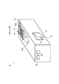
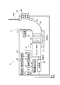
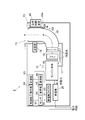
- the power generation system 1 includes an engine 10, a generator 20, a duct 30, a load test device 40, a switching device (state switching device) 45, a power storage device 50, a control unit 61, an operation unit 62, a measurement unit 63, A temperature sensor 64, a display unit 65, a communication unit 66, and a case 70 are provided (see FIGS. 1 to 8).
- the engine 10 is a device that generates a rotational force based on the explosive force of a gas such as gasoline and applies the rotational force to the generator 20, and a radiator that performs heat exchange of the coolant flowing through the engine body 11 and the engine body 11. 13.
- a fan 15 for cooling the radiator 13, an exhaust gas pipe 17, and a silencer (muffler) 18 are provided.
- the cylinder block and the cylinder head around the combustion chamber of the engine body 11 are provided with a water jacket, and cooling water passes through the water jacket, thereby suppressing the heating of the engine body 11 due to combustion.
- the cooling water heated by passing through the water jacket is cooled by blowing air from the fan 15 when passing through the radiator 13 (radiator core).
- the cooling water circulates inside the water jacket and the radiator 13 by a water pump (not shown).
- the fan 15 is a device that sends cooling air to the radiator 13 and may be driven based on the rotational force generated in the engine body 11 or driven based on an electric motor (not shown). Also good.
- the fan 15 is not only for cooling the radiator 13, but also for the resistor R of the load test apparatus 40 disposed on the cooling air flow path flowing from the fan 15 and downstream of the radiator 13 during the load test. Also used for cooling.
- the radiator 13 is disposed on the side of the engine body 11 so that the surface of the radiator core facing the fan 15 is substantially perpendicular to the horizontal direction.
- the fan 15 is disposed between the engine body 11 and the radiator 13 so as to be blown sideways and directed toward the radiator core of the radiator 13.
- the exhaust gas pipe 17 is a guide path that exhausts exhaust gas discharged from the engine body 11 to the outside from the upper part of the case 70, and extends to an opening (upper surface opening 71) provided in the upper part of the case 70.
- a silencer 18 that reduces exhaust noise is provided in the guide path.
- the generator 20 is a device that converts the rotational force obtained by the engine body 11 into electricity (a device that generates electricity), and the electric power obtained by the power generation is supplied to an external electric appliance connected to the generator 20.
- the electricity is stored in the electricity storage device 50.
- the generator 20 When performing a load test, the generator 20 is electrically connected to the load test apparatus 40, and the electrical connection with an external electric appliance is interrupted.
- the duct 30 has a substantially L-shaped flow path when viewed from the side, and is a guide path that guides the lateral air flow from the fan 15 upward.
- the inlet faces the radiator core of the radiator 13 and the outlet opens on the upper surface. It faces 71.
- the load test apparatus 40 has an upper surface and a lower surface that are open, and a plurality of rod-shaped resistors R parallel to the horizontal direction are arranged in series with a predetermined interval, and one or more resistors are arranged in the vertical direction. Used to perform a load test of the generator 20.
- the switching device 45 is arranged such that the resistor R of the load test device 40 is located on the cooling air flow path from the fan 15 and at the first position downstream of the radiator 13. Is used to move the load testing device 40 (see FIGS. 1 to 3).
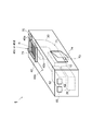
- the load test apparatus 40 is moved using the switching device 45 so that the load test apparatus 40 is located at the second position outside the flow path (FIGS. 4 to 5). 6).
- the load test device 40 may be arranged on the upper surface of the case 70, or may be arranged inside the case 70 at a position close to the upper surface.
- the capacity of the load test apparatus 40 is at least 25% or more with respect to the rated output of the generator 20, and is preferably 70% or less.
- the load test apparatus 40 desirably has a capacity of 8.75 to 24.5 kW.
- the switching device 45 is a device used to remove the load test device 40 from the cooling air flow path from the fan 15 or to position the load test device 40 on the flow channel and downstream of the radiator 13.
- an actuator 45a that moves the load test device 40 in the horizontal direction on the case 70 and a rail, a groove, and the like are held in a state in which the load test device 40 is slidable in the horizontal direction.
- a guide 45b is held in a guide 45b.
- the load test device 40 is moved to a position facing the upper surface opening 71 by the actuator 45a, that is, the first position on the flow path of the cooling air from the fan 15 (see FIGS. 1 to 3).
- the load test device 40 is moved to a position not facing the upper surface opening 71 by the actuator 45a, that is, to a second position outside the flow path of the cooling air from the fan 15 (FIGS. 4 to 6). reference).
- the generator 20 Is provided with a power supply control unit that maintains power supply from the generator 20 to the load test apparatus 40 when the load test apparatus 40 is removed from the flow path. desirable.
- the power supply control unit is connected to the generator 20 and arranged near the upper surface opening 71.
- the load test device 40 comes into contact with the load test device 40.
- the 1st terminal part 45c electrically connected with the resistor R can be considered.
- the generator 20 and the load test apparatus 40 are electrically connected via the first terminal portion 45c.
- the load test device 40 When the load test device 40 is removed from the flow path, the load test device 40 is in a non-contact state with the first terminal portion 45c, and the electrical connection state between the generator 20 and the load test device 40 is released.
- the position detection sensor 45d that detects whether or not the load test apparatus 40 is in the first position, and the generator 20 only when the position detection sensor 45d detects that the load test apparatus 40 is in the first position. It is also conceivable that the control unit 61 that supplies power to the resistor R of the load test device 40 functions as a power supply control unit.
- the mode in which the load test device 40 is automatically moved to the first position or the second position by the actuator 45a has been described.
- the load test device is manually installed by the user without providing the actuator 45a.
- the form which moves 40 to a 1st position or a 2nd position may be sufficient.
- the power storage device 50 includes a power storage unit 51 and an AC / DC converter 53.
- the power storage unit 51 is connected to the generator 20 via the AC / DC converter 53 and stores the power obtained by the power generator 20 such as a battery or a capacitor. , And supplied to an external electric appliance connected to the power storage device 50.
- the power storage device 50 may be connected to an AC power source (not shown) and used as an emergency power source.
- the control unit 61 performs control of operation of each part of the power generation system 1 (operation control of the engine 10 and the generator 20, control of each part of the load test device 40, operation control of the actuator 45a, power storage control of the power storage device 50, etc.). Device.
- the control unit 61 switches the resistor R of the load test apparatus 40 and the generator 20 electrically, and drives the actuator 45a to place the load test apparatus 40 in the first position.
- the movement control is performed to move the engine body 11 and the fan 15. It is desirable that the cooling water is circulated inside the engine body without passing through the radiator 13 until the temperature of the cooling water reaches a predetermined temperature or higher.
- the fan 15 When performing the load test, the fan 15 is used not only for cooling the radiator 13 but also for cooling the resistor R of the load test apparatus 40. Therefore, when the rotational speed can be controlled, such as driving with an electric motor. It is desirable to drive the engine 10 and the generator 20 with a larger output (higher rotational speed) than when the engine 10 and the generator 20 are driven without performing a load test.
- the cooling water passing through the radiator core of the radiator 13 is at most about 80 ° C. and lower than the temperature of the resistor R of the load test device 40 (about 200 ° C.), so the output control of the fan 15 is not performed. Even so, it is possible to cool the resistor R of the load test apparatus 40 with the air after heat exchange in the radiator 13.
- the operation unit 62 is used to perform an on / off operation of the engine 10 and the generator 20, an on / off operation of a load test of the generator 20 using the load test apparatus 40, a load amount, and a date and time setting for performing the load test. .
- the measuring unit 63 is connected to the generator 20, and the number of times the load test of the generator 20 using the load test apparatus 40 is performed. In the load test, a predetermined load amount (for example, 30% of the rated output of the generator 20). ) Is applied to the generator 20, and the measured load amount actually applied to the generator 20, and the time during which the measured load amount is equal to or greater than the predetermined load amount in the load test are measured.
- the measurement result is displayed on the display unit 65. Further, the measurement result may be transmitted to an external device via the communication unit 66 or recorded in a recording unit (not shown).
- the temperature sensor 64 measures the ambient temperature of the engine 10 or the generator 20 and outputs it to the control unit 61 when performing a load test.
- a threshold value for example, a temperature corresponding to a load test condition defined by a law such as the Fire Service Act (40 ° C. or the like
- the control unit 61 may decrease the ambient temperature.
- the control unit 61 stops the load test and causes the display unit 65 to display a warning.
- another temperature sensor (not shown) is provided in the vicinity of the load test apparatus 40, and when the ambient temperature of the load test apparatus 40 does not fall below a certain value (for example, 200 ° C.) even by cooling by the fan 15, The control unit 61 may cancel the load test and display a warning on the display unit 65.
- a certain value for example, 200 ° C.
- the display unit 65 displays information related to the load test such as the operating state of the engine 10, the generator 20, and the load test apparatus 40, particularly the measurement result by the measurement unit 63 and the ambient temperature of the engine 10 or the generator 20 by the temperature sensor 64.
- the communication unit 66 is a device that transmits and receives signals to and from a device external to the power generation system 1 (for example, a computer used to manage the power generation system 1) via a network.
- the information is transmitted to an external device, or information on the on / off operation of the load test and the date / time setting for performing the load test is received from the external device.
- the case 70 is a casing that covers members (including at least the upper surface, the side surface, the front surface, and the back surface) of the power generation system 1 such as the load test apparatus 40, and the operation unit 62 and the display unit 65 are provided on the back surface.
- the case 70 is provided with an upper surface opening 71 on the upper surface and above the outlet of the duct 30.
- the upper surface opening 71 is preferably provided with a slit-like lid (not shown) so that rainwater is difficult to enter.
- the cooling air passes through the load test device 40 through the duct 30, the cooling air easily passes (so that the resistor R of the load test device 40 does not obstruct the passage of the cooling air).
- 30 and the upper surface opening 71 of the case 70 are preferably wider than the region where the resistors R of the load test apparatus 40 are arranged.
- case 70 is a side surface, and a side opening 73 is provided on the side of the engine body 11, the fan 15, and the generator 20, and an opening / closing door 74 is provided in the side opening 73.
- an opening / closing door (not shown) is provided on the back surface of the case 70 (on the side where the power storage device 50 and the generator 20 are provided), and the power storage device 50 and the generator 20 are connected to external electric appliances through the opening / closing door.
- the operation unit 62 and the display unit 65 may be provided on the back surface of the case 70 and inside the opening / closing door.
- the cooling of the load test apparatus 40 can also be used as the fan 15 that cools the radiator 13 of the engine 10
- the configuration of the cooling member of the power generation system 1 including the load test apparatus 40 can be simplified.
- the load test device 40 Since the load test device 40 is arranged at the second position outside the flow path of the cooling air from the fan 15 using the switching device 45 at times other than the load test, it is normally used (at the time other than the load test).
- the resistor R of the load test apparatus 40 is not exposed to the cooling air from the fan 15. For this reason, it is possible to shorten the time for which the radiator 13 is exposed to the warm air after cooling, and the configuration of the load testing device 40 such as the resistor R as compared with the form in which the radiator 13 is always exposed to the warm air after cooling. It becomes possible to delay the deterioration of parts.
- the switching device 45 is used to place the load test device 40 at the first position on the flow path of the cooling air from the fan 15, so that the warm air after cooling of the radiator 13 is used as the load test device.
- the resistor R of the load test apparatus 40 can be cooled.
- the exhaust gas of the engine body 11 can be discharged from the upper surface opening 71.
- the minimum size (dimensions and capacity) necessary for the performance of the generator 20 is optimal.
- the engine 10 and the load test apparatus 40 can be combined. In particular, it is possible to combine the minimum load test apparatus 40 necessary for performing a load test at a predetermined load ratio (for example, 25% to 70%) with respect to the rated output of the generator 20.
- the engine 10 and the generator 20 are housed in one housing (case 70), the engine 10 and the generator 20 are automatically controlled by controlling them using the control unit 61. , And a load test is performed via the load test device 40, and the result is displayed on the display unit 65, transmitted to an external device via the communication unit 66, or the load test is controlled from an external device. It is also possible to do. It is also easy to prevent tampering of the load test.
- the load test apparatus 40 when the load test apparatus 40 is arranged on the upper surface of the case 70, the load test apparatus 40 is simply added to the case 70 housing the engine 10 and the generator 20, and the power generation system 1 in the first embodiment is configured. Can be formed.
- the load test device 40 by changing the position of the load test device 40 using the switching device 45 (guide 45b or the like), the load test device 40 is removed from the flow path of the cooling air from the fan 15 or on the flow path.
- the load test device 40 is positioned downstream of the radiator 13.
- another switching device 45 flow channel switching plate 45 e
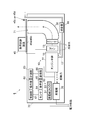
- the load test device 40 may be removed from the cooling air flow channel, or the load test device 40 may be positioned on the flow channel and downstream of the radiator 13 (second embodiment, FIGS. 9 to 9). 11).
- a resistor group in which a plurality of rod-like resistors R parallel to the horizontal direction and arranged in series at a predetermined interval is connected in series is opened in another horizontal direction.
- One or more stages are arranged in the front-rear direction away from the case 70 and are used to perform a load test of the generator 20 and are fixed above the front surface of the case 70.
- the case 70 in the second embodiment is provided with an upper surface opening 71 and a front surface opening 72 at a portion facing the load test apparatus 40 on the front surface.
- the duct 30 according to the second embodiment has a substantially L-shaped channel when viewed from the side, and is a guide path that guides the horizontal air flow from the fan 15 upward, with an inlet facing the radiator core of the radiator 13.
- One of the outlets (first outlet) faces the upper surface opening 71, and the other outlet (second outlet) faces the front opening 72 (load test apparatus 40 provided on the front surface of the case 70).
- the switching device 45 in the second embodiment includes a flow path switching plate 45e that shields one of the first outlet and the second outlet and opens the other.
- the flow path switching plate 45e is disposed so as to be positioned at one of the outlets of the duct 30 (the first outlet that does not face the load test device 40) (first state, see FIG. 9).
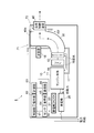
- the duct 30 is disposed so as to be located between the other outlet of the duct 30 (second outlet facing the load test apparatus 40) and the load test apparatus 40 (second state, see FIG. 11).
- the flow path switching plate 45e is rotated from the first state (see FIG. 9), the end opposite to the rotation shaft is lifted upward (see FIG. 10), and then lowered downward to be in the second state (see FIG. 9). 11). Further, the flow path switching plate 45e is lifted upward (see FIG. 10) from the second state (see FIG. 11), and then rotated to be switched to the first state (see FIG. 9).
- the flow path switching plate 45e may be configured to be switched between the first state and the second state by another method.
- the other side of the outlet of the duct 30 (second outlet, front opening 72) is shielded by using the flow path switching plate 45e, and one of the outlets of the duct 30 (first outlet, upper surface opening 71) is blocked. Since it opens, the load test apparatus 40 is removed from the flow path of the cooling air from the fan 15, and the resistor R of the load test apparatus 40 is cooled from the fan 15 during normal use (other than the load test). Not exposed to the wind. For this reason, it is possible to shorten the time for which the radiator 13 is exposed to the warm air after cooling, and the configuration of the load testing device 40 such as the resistor R as compared with the form in which the radiator 13 is always exposed to the warm air after cooling. It becomes possible to delay the deterioration of parts.
- the load test device 40 is positioned on the flow path of the cooling air from the fan 15, and the warm air after the cooling of the radiator 13 flows to the load test device 40, and the resistor of the load test device 40. R can be cooled.
- the flow path switching plate 45e may be manually switched between the first state and the second state, or may be automatically switched using an actuator (not shown) or the like.
- the flow path switching plate 45e opens the other outlet (second outlet, front opening 72) of the duct 30 so that power is not supplied to the resistor R of the load testing apparatus 40 by mistake at a time other than the load test.
- the generator 20 It is desirable to provide a power supply control unit that cuts off the power supply from the power supply to the load test apparatus 40.
- the power supply control unit is connected to the generator 20 and is disposed under the load test apparatus 40.
- the flow path switching plate 45e opens the other outlet (second outlet, front opening 72) of the duct 30.
- a second terminal portion 45f that contacts the load test device 40 with an upward biasing force and is electrically connected to the resistor R of the load test device 40 is conceivable.
- the generator 20 and the load test apparatus 40 are electrically connected via the second terminal portion 45f.
- the second terminal portion 45f is pushed down by the flow path switching plate 45e, and the load test apparatus 40 is The terminal portion 45f is brought into a non-contact state, and the electrical connection state between the generator 20 and the load test apparatus 40 is released.
- the switching device 45 is provided.
- Using and changing the position of the load test device 40 (first embodiment) and changing the flow path (second embodiment) may be both forms, or only one is performed. It may be.
Landscapes
- Engineering & Computer Science (AREA)
- Physics & Mathematics (AREA)
- General Physics & Mathematics (AREA)
- Chemical & Material Sciences (AREA)
- Combustion & Propulsion (AREA)
- Mechanical Engineering (AREA)
- General Engineering & Computer Science (AREA)
- Power Engineering (AREA)
- Microelectronics & Electronic Packaging (AREA)
- Tests Of Circuit Breakers, Generators, And Electric Motors (AREA)
- Connection Of Motors, Electrical Generators, Mechanical Devices, And The Like (AREA)
Abstract
構成部品が劣化しにくい負荷試験装置を含む発電システムを提供する。 発電システム1は、エンジン本体11と、エンジン本体11の内部を流れる冷却水の熱交換を行うラジエーター13と、ラジエーター13を冷却するファン15とを有するエンジン10を備える。エンジン本体11で得られた回転力を電気に変換する発電機20を備える。複数の抵抗器を有し、発電機20の負荷試験を行うために使用される負荷試験装置40を備える。ファン15からの冷却風の流路から負荷試験装置40を外したり、負荷試験の時に流路上であってラジエーター13よりも下流に負荷試験装置40を位置させたりするために、負荷試験装置40の位置を変えることと流路を変えることの少なくとも一方を行う切替装置(45a、45b)を備える。
Description
本発明は、負荷試験装置を含む発電システムに関する。
従来、特許文献1のように、発電機と負荷試験装置とが一体となった装置が提案されている。
しかし、負荷試験装置はファンからの冷却風にさらされ続けるため、負荷試験装置の構成部品が劣化するおそれがある。
ない。
ない。
したがって本発明の目的は、構成部品が劣化しにくい負荷試験装置を含む発電システムを提供することである。
本発明に係る発電システムは、エンジン本体と、エンジン本体の内部を流れる冷却水の熱交換を行うラジエーターと、ラジエーターを冷却するファンとを有するエンジンと、エンジン本体で得られた回転力を電気に変換する発電機と、複数の抵抗器を有し、発電機の負荷試験を行うために使用される負荷試験装置と、ファンからの冷却風の流路から負荷試験装置を外したり、負荷試験の時に流路上であってラジエーターよりも下流に負荷試験装置を位置させたりするために、負荷試験装置の位置を変えることと流路を変えることの少なくとも一方を行う切替装置とを備える。
負荷試験装置の冷却は、エンジンのラジエーターを冷却するファンを兼用出来るため、負荷試験装置を含む発電システムの冷却部材の構成を簡素化出来る。
負荷試験装置は、負荷試験以外の時には、切替装置を使って、ファンからの冷却風の流路から外れるため、通常使用時(負荷試験以外の時)には、負荷試験装置の抵抗器などはファンからの冷却風にさらされない。
このため、ラジエーターの冷却後の温風にさらされる時間を短くすることが出来、常時、ラジエーターの冷却後の温風にさらされる形態に比べて、抵抗器など負荷試験装置の構成部品の劣化を遅らせることが可能になる。
このため、ラジエーターの冷却後の温風にさらされる時間を短くすることが出来、常時、ラジエーターの冷却後の温風にさらされる形態に比べて、抵抗器など負荷試験装置の構成部品の劣化を遅らせることが可能になる。
また、負荷試験時は、切替装置を使って、ファンからの冷却風の流路上に負荷試験装置が配置されるため、ラジエーターの冷却後の温風が負荷試験装置に流れ、負荷試験装置の抵抗器を冷却することが出来る。
好ましくは、切替装置は、負荷試験装置の位置を変えるために、負荷試験装置を摺動可能な状態で保持するガイドを有する。
さらに好ましくは、負荷試験装置を流路上であってラジエーターよりも下流に位置させた時に、発電機から負荷試験装置への電力供給を維持し、負荷試験装置が流路から外れた時に、発電機から負荷試験装置への電力供給を遮断する電力供給制御部を更に備える。
負荷試験以外の時に、誤って、負荷試験装置の抵抗器に電力供給がされるのを防止することが出来る。
また、好ましくは、エンジンと、発電機を収納するケースを更に備え、負荷試験装置と、ガイドは、ケースの上部に配置され、負荷試験装置が流路から外れた時に、負荷試験装置の少なくとも上面を覆うカバーが設けられる。
エンジンと発電機を収納したケースに簡単に負荷試験装置を追加して、発電システムを形成することが出来る。
また、好ましくは、流路の出口は、負荷試験装置と対向しない第1出口と、負荷試験装置と対向する第2出口を有し、切替装置は、流路を変えるために、第1出口と第2出口の一方を遮蔽し他方を開口させる流路切替板を有する。
さらに好ましくは、エンジンと、発電機を収納するケースを更に備え、第1出口は、ケースの上面開口に設けられ、第2出口は、ケースの開口に設けられ、第1出口を遮蔽し第2出口を開口させる場合には、上面開口の上に流路切替板が配置され、第2出口を遮蔽し第1出口を開口させる場合には、前面開口と負荷試験装置の間に流路切替板が配置される。
また、好ましくは、流路切替板が第2出口を開口させた時に、発電機から負荷試験装置への電力供給を維持し、流路切替板が第2出口を遮蔽した時に、発電機から負荷試験装置への電力供給を遮断する電力供給制御部を更に備える。
以上のように本発明によれば、構成部品が劣化しにくい負荷試験装置を含む発電システムを提供することができる。
以下、本実施形態について、図を用いて説明する。第1実施形態における発電システム1は、エンジン10、発電機20、ダクト30、負荷試験装置40、切替装置(状態切替装置)45、蓄電装置50、制御部61、操作部62、計測部63、温度センサ64、表示部65、通信部66、ケース70を備える(図1~図8参照)。
なお、図2と図5の斜視図では、ケース70の内部に収められる発電機20などの機器を点線で示すが、制御部61と計測部63と温度センサ64と通信部66は図示を省略している。
エンジン10は、ガソリンなどガスの爆発力に基づいて回転力を発生させ、発電機20に当該回転力を与える装置で、エンジン本体11、エンジン本体11の内部を流れる冷却水の熱交換を行うラジエーター13、ラジエーター13を冷却するファン15、排気ガス管17、消音器(マフラー)18を有する。
エンジン本体11の燃焼室の周囲にあるシリンダーブロックやシリンダーヘッドには、ウォータージャケットが設けられ、ウォータージャケットに冷却水が通ることにより、燃焼によるエンジン本体11の加熱を抑えられる。ウォータージャケットを通過したことで加熱した冷却水は、ラジエーター13(のラジエーターコア)を通る際に、ファン15からの送風により冷却される。冷却水は、図示しないウォーターポンプによって、ウォータージャケットやラジエーター13の内部を循環する。
ファン15は、ラジエーター13に冷却用の空気を送る装置で、エンジン本体11で発生した回転力に基づいて駆動する形態であってもよいし、図示しない電動モーターに基づいて駆動する形態であってもよい。
第1実施形態では、ファン15は、ラジエーター13の冷却の他、負荷試験時にファン15から流れる冷却風の流路上であってラジエーター13よりも下流に配置された負荷試験装置40の抵抗器Rの冷却にも使用される。
ラジエーター13は、ラジエーターコアのファン15と対向する面が水平方向と略垂直になるように、エンジン本体11の側部に配置される。ファン15は、横向きで且つラジエーター13のラジエーターコアの方に向けて送風が行われるように、エンジン本体11とラジエーター13の間に配置される。
排気ガス管17は、エンジン本体11から排出される排気ガスをケース70の上部から外部に排出させる誘導路で、ケース70の上部に設けられた開口部(上面開口71)に延びる。
当該誘導路には、排気音を低減させる消音器18が設けられる。
当該誘導路には、排気音を低減させる消音器18が設けられる。
発電機20は、エンジン本体11で得られた回転力を電気に変換する装置(発電する装置)で、発電により得られた電力は、発電機20に接続された外部の電気器具に供給されたり、蓄電装置50に蓄電されたりする。
負荷試験を行う際には、発電機20は、負荷試験装置40と電気的に接続され、外部の電気器具との電気的な接続は遮断される。
ダクト30は、流路が側面から見て略L字形状を有し、ファン15からの横向きの送風を上方向に導く誘導路で、入口がラジエーター13のラジエーターコアと対向し、出口が上面開口71と対向する。
負荷試験装置40は、上面と下面が開口し、水平方向に平行な棒状の抵抗器Rが所定の間隔を空けて複数本並べられ直列接続された抵抗器群が、鉛直方向に1段以上並べられたもので、発電機20の負荷試験を行うために用いられる。
第1実施形態では、負荷試験時に、負荷試験装置40の抵抗器Rが、ファン15からの冷却風の流路上で、且つラジエーター13よりも下流の第1位置に位置するように、切替装置45を使って、負荷試験装置40が移動せしめられる(図1~図3参照)。
また、負荷試験以外の時は、負荷試験装置40は、当該流路から外れた第2位置に位置するように、切替装置45を使って、負荷試験装置40が移動せしめられる(図4~図6参照)。
また、負荷試験以外の時は、負荷試験装置40は、当該流路から外れた第2位置に位置するように、切替装置45を使って、負荷試験装置40が移動せしめられる(図4~図6参照)。
負荷試験装置40は、図示するように、ケース70の上面に配置する形態であってもよいし、ケース70の内部であって上面に近い位置に配置する形態であってもよい。
ケース70の上面に負荷試験装置40を配置する場合には、負荷試験以外の時に抵抗器Rなどが風雨にさらされないように、負荷試験装置40を囲むカバー43が設けられるのが望ましい(図7、図8参照)。
負荷試験装置40の容量は、発電機20の定格出力に対して少なくとも25%以上有するものであり、70%以下であることが望ましい。例えば、発電機20の定格出力が35kVAである場合には、負荷試験装置40は8.75~24.5kWの容量を有するのが望ましい。
切替装置45は、ファン15からの冷却風の流路から負荷試験装置40を外したり、当該流路上であってラジエーター13の下流に負荷試験装置40を位置させたりするために使用される装置で、第1実施形態では、負荷試験装置40をケース70の上で水平方向に移動させるアクチュエータ45aと、レールや溝などで構成され負荷試験装置40を当該水平方向に摺動可能な状態で保持するガイド45bとを有する。
負荷試験時は、アクチュエータ45aによって、負荷試験装置40は上面開口71と対向する位置、すなわちファン15からの冷却風の流路上の第1位置に移動せしめられる(図1~図3参照)。
負荷試験以外の時は、アクチュエータ45aによって、負荷試験装置40は上面開口71と対向しない位置、すなわちファン15からの冷却風の流路から外れた第2位置に移動せしめられる(図4~図6参照)。
負荷試験以外の時に、誤って、負荷試験装置40の抵抗器Rに電力供給がされないように、負荷試験装置40を当該流路上であってラジエーター13よりも下流に位置させた時に、発電機20から負荷試験装置40への電力供給を維持し、負荷試験装置40が当該流路から外れた時に、発電機20から負荷試験装置40への電力供給を遮断する電力供給制御部が設けられるのが望ましい。
電力供給制御部としては、発電機20と接続され、上面開口71の近傍などに配置され、負荷試験装置40が第1位置に位置した時に、負荷試験装置40と接触し、負荷試験装置40の抵抗器Rと電気的に接続する第1端子部45cが考えられる。発電機20と負荷試験装置40とは、当該第1端子部45cを介して電気的な接続が行われる。
負荷試験装置40が当該流路から外れた時、負荷試験装置40は第1端子部45cと非接触状態となり、発電機20と負荷試験装置40の電気的な接続状態が解除される。
また、負荷試験装置40が第1位置にいるか否かを検知する位置検出センサ45dと、当該位置検出センサ45dによって負荷試験装置40が第1位置にいることが検知された時にだけ、発電機20から負荷試験装置40の抵抗器Rへの電力供給を行わせる制御部61が、電力供給制御部として機能する形態も考えられる。
なお、第1実施形態では、アクチュエータ45aによって自動的に負荷試験装置40を第1位置や第2位置に移動させる形態を説明したが、アクチュエータ45aを設けずに、使用者による手動で負荷試験装置40を第1位置や第2位置に移動させる形態であってもよい。
蓄電装置50は、蓄電部51と、AC/DCコンバーター53を有する。蓄電部51は、AC/DCコンバーター53を介して、発電機20と接続され、バッテリーやコンデンサなど、発電機20で得られた電力を蓄える装置で、蓄えた電力は、発電システム1の各部や、蓄電装置50に接続された外部の電気器具に供給される。
なお、蓄電装置50は、図示しないAC電源と接続されて、非常用電源として用いられる形態であってもよい。
制御部61は、発電システム1の各部の動作制御(エンジン10や発電機20の動作制御、負荷試験装置40の各部の制御、アクチュエータ45aの動作制御、蓄電装置50の蓄電制御など)を行う制御装置である。
負荷試験を行う際には、制御部61は、負荷試験装置40の抵抗器Rと発電機20とを電気的に接続させるスイッチ制御と、アクチュエータ45aを駆動して負荷試験装置40を第1位置に移動させる移動制御を行い、エンジン本体11やファン15を駆動させる。なお、冷却水の温度が所定の温度以上になるまでは、ラジエーター13を通らずに、エンジン本体の内部で冷却水を循環させるのが望ましい。
負荷試験を行う際に、ファン15は、ラジエーター13の冷却だけでなく、負荷試験装置40の抵抗器Rの冷却にも使用されるため、電動モーターで駆動するなど回転数を制御出来る場合には、負荷試験を行わずにエンジン10や発電機20を駆動する際よりも大きい出力(大きい回転数)で駆動させるのが望ましい。
ただし、ラジエーター13のラジエーターコアを通過する冷却水は高くても80℃前後であり、負荷試験装置40の抵抗器Rの温度(約200℃)よりは低いため、ファン15の出力制御を行わなかったとしても、ラジエーター13での熱交換後の空気で、負荷試験装置40の抵抗器Rを冷却することは可能である。
操作部62は、エンジン10や発電機20のオンオフ操作や、負荷試験装置40を使った発電機20の負荷試験のオンオフ操作や負荷量や該負荷試験を行う日時設定を行うために使用される。
計測部63は、発電機20と接続され、負荷試験装置40を使った発電機20の負荷試験を行った回数、該負荷試験において所定の負荷量(例えば、発電機20の定格出力の30%)を発電機20にかけたことによって実際に発電機20にかかっている測定負荷量、該負荷試験において該測定負荷量が該所定の負荷量以上になっている時間を測定する。測定結果は、表示部65に表示される。また、測定結果は、通信部66を介して外部の装置に送信したり、図示しない記録部に記録させたりしてもよい。
温度センサ64は、負荷試験を行う際に、エンジン10若しくは発電機20の周囲温度を測定し、制御部61に出力する。制御部61は、該周囲温度が閾値(例えば、消防法などの法律で定められた負荷試験時の条件に対応した温度(40℃など))よりも高い場合には、該周囲温度が下がるように、ファン15の出力(回転数)を上げ、それでも該周囲温度が閾値以下にならない場合は、制御部61は、負荷試験を中止し、表示部65に警告表示させる。
また、負荷試験装置40の近傍にも別の温度センサ(不図示)を設け、負荷試験装置40の周囲温度がファン15による冷却などでも一定値(例えば、200℃)を下回らない場合には、制御部61は、負荷試験を中止し、表示部65に警告表示させてもよい。
表示部65は、エンジン10、発電機20、負荷試験装置40の運転状態、特に計測部63による計測結果や温度センサ64によるエンジン10若しくは発電機20の周囲温度など負荷試験に関する情報を表示する。
通信部66は、ネットワークを介して、発電システム1の外部の装置(例えば、発電システム1の管理するために使用されるコンピュータ)と信号送受信を行う装置で、発電機20の負荷試験に関する情報を外部の装置に送信したり、外部の装置から負荷試験のオンオフ操作や該負荷試験を行う日時設定に関する情報を受信したりする。
ケース70は、負荷試験装置40など、発電システム1を構成する部材(の少なくとも上面と側面と前面と背面)を覆う筐体であり、背面に操作部62や表示部65が設けられる。
また、ケース70は、上面であってダクト30の出口の上方に上面開口71が設けられる。上面開口71には、雨水が入りにくくなるようにスリット状の蓋(不図示)が設けられるのが望ましい。
ダクト30を介して負荷試験装置40に冷却風が通過する際に、冷却風が通過しやすくするため(負荷試験装置40の抵抗器Rが冷却風の通過の妨げになりにくくするため)、ダクト30における流路やケース70の上面開口71は、負荷試験装置40の抵抗器Rが並べられた領域よりも広くしておくのが望ましい。
また、ケース70は、側面であってエンジン本体11やファン15や発電機20の側部に側面開口73が設けられ、側面開口73には開閉扉74が設けられる。
また、ケース70の背面(蓄電装置50や発電機20が設けられた側)には、図示しない開閉ドアが設けられ、当該開閉ドアを介して、蓄電装置50や発電機20が外部の電気器具と接続される。操作部62や表示部65は、ケース70の背面であって当該開閉ドアの内側に設けられる形態であってもよい。
第1実施形態では、負荷試験装置40の冷却は、エンジン10のラジエーター13を冷却するファン15を兼用出来るため、負荷試験装置40を含む発電システム1の冷却部材の構成を簡素化出来る。
負荷試験装置40は、負荷試験以外の時には、切替装置45を使って、ファン15からの冷却風の流路から外れた第2位置に配置されるため、通常使用時(負荷試験以外の時)には、負荷試験装置40の抵抗器Rなどはファン15からの冷却風にさらされない。
このため、ラジエーター13の冷却後の温風にさらされる時間を短くすることが出来、常時、ラジエーター13の冷却後の温風にさらされる形態に比べて、抵抗器Rなど負荷試験装置40の構成部品の劣化を遅らせることが可能になる。
このため、ラジエーター13の冷却後の温風にさらされる時間を短くすることが出来、常時、ラジエーター13の冷却後の温風にさらされる形態に比べて、抵抗器Rなど負荷試験装置40の構成部品の劣化を遅らせることが可能になる。
また、負荷試験時は、切替装置45を使って、ファン15からの冷却風の流路上の第1位置に負荷試験装置40が配置されるため、ラジエーター13の冷却後の温風が負荷試験装置40に流れ、負荷試験装置40の抵抗器Rを冷却することが出来る。
また、ラジエーター13や負荷試験装置40における熱交換後の熱風はケース70の上面開口71から上方に排出されるため、使用者に熱風が当たるのを防止することが出来る。
また、上面開口71からエンジン本体11の排気ガスも排出することが可能になる。
また、上面開口71や側面開口73から外部の空気を導入出来るので、エンジン10若しくは発電機20の周囲温度上昇を抑えることが可能になる。
また、エンジン10、発電機20、負荷試験装置40が1つの筐体(ケース70)に収められるので、発電機20の性能に合わせて必要最小限の大きさ(寸法や容量)で且つ最適なエンジン10や負荷試験装置40を組み合わせることが出来る。特に、発電機20の定格出力に対する所定の割合(たとえば、25%~70%)の負荷量で負荷試験を行うために必要最小限の負荷試験装置40を組み合わせることが出来る。
また、エンジン10、発電機20、負荷試験装置40が1つの筐体(ケース70)に収められるので、制御部61を使ってこれらを制御することで、自動的に、エンジン10や発電機20を駆動し、負荷試験装置40を介して負荷試験を行い、その結果を表示部65に表示させたり、通信部66を介して外部の装置に送信したり外部の装置から負荷試験を制御したりすることも可能になる。また、負荷試験の改ざん防止も容易に行える。
特に、ケース70の上面に負荷試験装置40を配置した場合には、エンジン10と発電機20を収納したケース70に簡単に負荷試験装置40を追加して、第1実施形態における発電システム1を形成することが出来る。
第1実施形態では、切替装置45(ガイド45bなど)を使って負荷試験装置40の位置を変えることにより、ファン15からの冷却風の流路から負荷試験装置40を外したり、当該流路上であってラジエーター13の下流に負荷試験装置40を位置させたりする形態を説明したが、別の切替装置45(流路切替板45e)を使って、当該流路を変えることにより、ファン15からの冷却風の流路から負荷試験装置40を外したり、当該流路上であってラジエーター13の下流に負荷試験装置40を位置させたりする形態であってもよい(第2実施形態、図9~図11参照)。
第2実施形態における負荷試験装置40は、側面が開口し、水平方向に平行な棒状の抵抗器Rが所定の間隔を空けて複数本並べられ直列接続された抵抗器群が、別の水平方向(ケース70から離れる前後方向)に1段以上並べられたもので、発電機20の負荷試験を行うために用いられ、ケース70の前面の上方に固定される。
第2実施形態におけるケース70は、上面開口71と、前面であって負荷試験装置40と対向する部分に前面開口72が設けられる。
第2実施形態におけるダクト30は、流路が側面から見て略L字形状を有し、ファン15からの横向きの送風を上方向に導く誘導路で、入口がラジエーター13のラジエーターコアと対向し、出口の一方(第1出口)が上面開口71と対向し、出口の他方(第2出口)が前面開口72(ケース70の前面に設けられた負荷試験装置40)と対向する。
第2実施形態における切替装置45は、第1出口と第2出口のいずれか一方を遮蔽し、他方を開口させる流路切替板45eを有する。
流路切替板45eは、負荷試験時は、ダクト30の出口の一方(負荷試験装置40と対向しない第1出口)に位置するように配置され(第1状態、図9参照)、負荷試験以外の時は、ダクト30の出口の他方(負荷試験装置40と対向する第2出口)と負荷試験装置40の間に位置するように配置される(第2状態、図11参照)。
流路切替板45eは、負荷試験時は、ダクト30の出口の一方(負荷試験装置40と対向しない第1出口)に位置するように配置され(第1状態、図9参照)、負荷試験以外の時は、ダクト30の出口の他方(負荷試験装置40と対向する第2出口)と負荷試験装置40の間に位置するように配置される(第2状態、図11参照)。
流路切替板45eは、第1状態(図9参照)から、回転して回転軸と反対側の端部が上方に持ち上げられ(図10参照)、その後下方に降ろされて第2状態(図11参照)に切り替えられる。
また、流路切替板45eは、第2状態(図11参照)から、上方に持ち上げられ(図10参照)、その後回転させて第1状態(図9参照)に切り替えられる。
ただし、流路切替板45eは、他の方法で第1状態と第2状態とが切り替えられる形態であってもよい。
また、流路切替板45eは、第2状態(図11参照)から、上方に持ち上げられ(図10参照)、その後回転させて第1状態(図9参照)に切り替えられる。
ただし、流路切替板45eは、他の方法で第1状態と第2状態とが切り替えられる形態であってもよい。
負荷試験以外の時には、流路切替板45eを使って、ダクト30の出口の他方(第2出口、前面開口72)が遮蔽され、ダクト30の出口の一方(第1出口、上面開口71)が開口するため、負荷試験装置40は、ファン15からの冷却風の流路から外れ、通常使用時(負荷試験以外の時)には、負荷試験装置40の抵抗器Rなどはファン15からの冷却風にさらされない。
このため、ラジエーター13の冷却後の温風にさらされる時間を短くすることが出来、常時、ラジエーター13の冷却後の温風にさらされる形態に比べて、抵抗器Rなど負荷試験装置40の構成部品の劣化を遅らせることが可能になる。
このため、ラジエーター13の冷却後の温風にさらされる時間を短くすることが出来、常時、ラジエーター13の冷却後の温風にさらされる形態に比べて、抵抗器Rなど負荷試験装置40の構成部品の劣化を遅らせることが可能になる。
また、負荷試験時は、流路切替板45eを使って、ダクト30の出口の一方(第1出口、上面開口71)が遮蔽され、ダクト30の出口の他方(第2出口、前面開口72)が開口するため、負荷試験装置40は、ファン15からの冷却風の流路上に位置することになり、ラジエーター13の冷却後の温風が負荷試験装置40に流れ、負荷試験装置40の抵抗器Rを冷却することが出来る。
流路切替板45eは、手動で第1状態と第2状態とが切り替えられる形態であってもよいし、アクチュエータ(不図示)などを使って自動的に切り替えられる形態であってもよい。
負荷試験以外の時に、誤って、負荷試験装置40の抵抗器Rに電力供給がされないように、流路切替板45eがダクト30の出口の他方(第2出口、前面開口72)を開口させている時に、発電機20から負荷試験装置40への電力供給を維持し、流路切替板45eがダクト30の出口の他方(第2出口、前面開口72)を遮蔽している時に、発電機20から負荷試験装置40への電力供給を遮断する電力供給制御部が設けられるのが望ましい。
電力供給制御部としては、発電機20と接続され、負荷試験装置40の下に配置され、流路切替板45eがダクト30の出口の他方(第2出口、前面開口72)を開口させている時に、上方向の付勢力で負荷試験装置40と接触し、負荷試験装置40の抵抗器Rと電気的に接続する第2端子部45fが考えられる。発電機20と負荷試験装置40とは、第2端子部45fを介して電気的な接続が行われる。
流路切替板45eがダクト30の出口の他方(第2出口、前面開口72)を遮蔽している時、流路切替板45eにより第2端子部45fが押し下げられ、負荷試験装置40は第2端子部45fと非接触状態となり、発電機20と負荷試験装置40の電気的な接続状態が解除される。
ファン15からの冷却風の流路から負荷試験装置40を外したり、負荷試験の時に当該流路上であってラジエーター13よりも下流に負荷試験装置40を位置させたりするために、切替装置45を使って、負荷試験装置40の位置を変えること(第1実施形態)と、当該流路を変えること(第2実施形態)は、両方を行う形態であってもよいし、一方だけを行う形態であってもよい。
1 発電システム
10 エンジン
11 エンジン本体
13 ラジエーター
15 ファン
17 排気ガス管
18 消音器
20 発電機
30 ダクト
40 負荷試験装置
43 カバー
45 切替装置
45a アクチュエータ
45b ガイド
45c 第1端子部
45d 位置検出センサ
45e 流路切替板
45f 第2端子部
50 蓄電装置
51 蓄電部
53 AC/DCコンバーター
61 制御部
62 操作部
63 計測部
64 温度センサ
65 表示部
66 通信部
70 ケース
71 上面開口
72 前面開口
73 側面開口
74 開閉扉
10 エンジン
11 エンジン本体
13 ラジエーター
15 ファン
17 排気ガス管
18 消音器
20 発電機
30 ダクト
40 負荷試験装置
43 カバー
45 切替装置
45a アクチュエータ
45b ガイド
45c 第1端子部
45d 位置検出センサ
45e 流路切替板
45f 第2端子部
50 蓄電装置
51 蓄電部
53 AC/DCコンバーター
61 制御部
62 操作部
63 計測部
64 温度センサ
65 表示部
66 通信部
70 ケース
71 上面開口
72 前面開口
73 側面開口
74 開閉扉
Claims (7)
- エンジン本体と、前記エンジン本体の内部を流れる冷却水の熱交換を行うラジエーターと、前記ラジエーターを冷却するファンとを有するエンジンと、
前記エンジン本体で得られた回転力を電気に変換する発電機と、
複数の抵抗器を有し、前記発電機の負荷試験を行うために使用される負荷試験装置と、
前記ファンからの冷却風の流路から前記負荷試験装置を外したり、前記負荷試験の時に前記流路上であって前記ラジエーターよりも下流に前記負荷試験装置を位置させたりするために、前記負荷試験装置の位置を変えることと前記流路を変えることの少なくとも一方を行う切替装置とを備えることを特徴とする発電システム。 - 前記切替装置は、前記負荷試験装置の位置を変えるために、前記負荷試験装置を摺動可能な状態で保持するガイドを有することを特徴とする請求項1に記載の発電システム。
- 前記負荷試験装置を前記流路上であって前記ラジエーターよりも下流に位置させた時に、前記発電機から前記負荷試験装置への電力供給を維持し、前記負荷試験装置が前記流路から外れた時に、前記発電機から前記負荷試験装置への電力供給を遮断する電力供給制御部を更に備えることを特徴とする請求項2に記載の発電システム。
- 前記エンジンと、前記発電機を収納するケースを更に備え、
前記負荷試験装置と、前記ガイドは、前記ケースの上部に配置され、
前記負荷試験装置が前記流路から外れた時に、前記負荷試験装置の少なくとも上面を覆うカバーが設けられることを特徴とする請求項2に記載の発電システム。 - 前記流路の出口は、前記負荷試験装置と対向しない第1出口と、前記負荷試験装置と対向する第2出口を有し、
前記切替装置は、前記流路を変えるために、前記第1出口と前記第2出口の一方を遮蔽し他方を開口させる流路切替板を有することを特徴とする請求項1に記載の発電システム。 - 前記エンジンと、前記発電機を収納するケースを更に備え、
前記第1出口は、前記ケースの上面開口に設けられ、
前記第2出口は、前記ケースの前面開口に設けられ、
前記第1出口を遮蔽し前記第2出口を開口させる場合には、前記上面開口の上に前記流路切替板が配置され、
前記第2出口を遮蔽し前記第1出口を開口させる場合には、前記前面開口と前記負荷試験装置の間に前記流路切替板が配置されることを特徴とする請求項5に記載の発電システム。 - 前記流路切替板が前記第2出口を開口させた時に、前記発電機から前記負荷試験装置への電力供給を維持し、前記流路切替板が前記第2出口を遮蔽した時に、前記発電機から前記負荷試験装置への電力供給を遮断する電力供給制御部を更に備えることを特徴とする請求項5に記載の発電システム。
Priority Applications (5)
| Application Number | Priority Date | Filing Date | Title |
|---|---|---|---|
| KR1020187013681A KR101929410B1 (ko) | 2016-02-25 | 2017-01-25 | 발전 시스템 |
| JP2017536909A JP6275346B2 (ja) | 2016-02-25 | 2017-01-25 | 発電システム |
| EP17756057.0A EP3422030B1 (en) | 2016-02-25 | 2017-01-25 | Electricity generating system |
| CN201780006459.4A CN108463735B (zh) | 2016-02-25 | 2017-01-25 | 发电系统 |
| US15/972,288 US10379163B2 (en) | 2016-02-25 | 2018-05-07 | Power generation system |
Applications Claiming Priority (2)
| Application Number | Priority Date | Filing Date | Title |
|---|---|---|---|
| JP2016-033733 | 2016-02-25 | ||
| JP2016033733 | 2016-02-25 |
Related Child Applications (1)
| Application Number | Title | Priority Date | Filing Date |
|---|---|---|---|
| US15/972,288 Continuation US10379163B2 (en) | 2016-02-25 | 2018-05-07 | Power generation system |
Publications (1)
| Publication Number | Publication Date |
|---|---|
| WO2017145615A1 true WO2017145615A1 (ja) | 2017-08-31 |
Family
ID=59685102
Family Applications (1)
| Application Number | Title | Priority Date | Filing Date |
|---|---|---|---|
| PCT/JP2017/002466 WO2017145615A1 (ja) | 2016-02-25 | 2017-01-25 | 発電システム |
Country Status (6)
| Country | Link |
|---|---|
| US (1) | US10379163B2 (ja) |
| EP (1) | EP3422030B1 (ja) |
| JP (1) | JP6275346B2 (ja) |
| KR (1) | KR101929410B1 (ja) |
| CN (1) | CN108463735B (ja) |
| WO (1) | WO2017145615A1 (ja) |
Cited By (3)
| Publication number | Priority date | Publication date | Assignee | Title |
|---|---|---|---|---|
| CN107797064A (zh) * | 2017-10-18 | 2018-03-13 | 重庆理工大学 | 一种小型永磁中频液冷发电机测试系统 |
| WO2020059159A1 (ja) * | 2018-09-18 | 2020-03-26 | 株式会社辰巳菱機 | 負荷抵抗器 |
| WO2021070461A1 (ja) * | 2019-10-08 | 2021-04-15 | 株式会社辰巳菱機 | 試験システム、試験システムを含む負荷試験装置 |
Families Citing this family (1)
| Publication number | Priority date | Publication date | Assignee | Title |
|---|---|---|---|---|
| CN113746267B (zh) * | 2021-07-22 | 2023-11-28 | 成都中车电机有限公司 | 一种发电机冷却通风装置 |
Citations (4)
| Publication number | Priority date | Publication date | Assignee | Title |
|---|---|---|---|---|
| JPH0743436A (ja) * | 1993-07-28 | 1995-02-14 | Tatsumi Riyouki:Kk | 自家用発電機等の切り替え型試験装置 |
| JP2001280585A (ja) * | 2000-03-29 | 2001-10-10 | Meidensha Corp | 発電装置 |
| WO2014162678A1 (ja) * | 2013-04-02 | 2014-10-09 | 株式会社辰巳菱機 | 発電システム |
| EP2899858A1 (en) * | 2014-01-24 | 2015-07-29 | Siemens Aktiengesellschaft | Electric generator arrangement with improved cooling system and operating method thereto |
Family Cites Families (17)
| Publication number | Priority date | Publication date | Assignee | Title |
|---|---|---|---|---|
| US2971596A (en) * | 1957-11-29 | 1961-02-14 | Gen Motors Corp | Vehicle speed control system |
| DE2019731C3 (de) | 1970-04-20 | 1974-11-21 | Ver Kesselwerke Ag | Verfahren zur Aufbereitung von Abwasserschlamm zur Verbesserung seiner Entwässerungseigenschaften und Vorrichtung zur Durchführung des Verfahrens |
| US4130794A (en) * | 1976-11-05 | 1978-12-19 | Cox C Eugene | Methods and means for identifying and testing circuit connections |
| JPS5420782A (en) | 1977-07-15 | 1979-02-16 | Fuji Electric Co Ltd | Jig for high temperature tension test |
| US5181387A (en) | 1985-04-03 | 1993-01-26 | Gershon Meckler | Air conditioning apparatus |
| US7254468B2 (en) * | 2001-12-21 | 2007-08-07 | Oshkosh Truck Corporation | Multi-network control system for a vehicle |
| US7545111B2 (en) * | 2006-12-22 | 2009-06-09 | Chrysler Llc | Testing inverter driven electric motor shut-off path |
| US20120235566A1 (en) * | 2008-09-27 | 2012-09-20 | Aristeidis Karalis | Tunable wireless energy transfer for lighting applications |
| JP2011071174A (ja) * | 2009-09-24 | 2011-04-07 | Renesas Electronics Corp | 半導体装置、及び半導体装置の特性劣化検出方法 |
| CN201594785U (zh) * | 2009-10-09 | 2010-09-29 | Abb瑞士有限公司 | 拉出电阻 |
| US8050879B2 (en) * | 2009-12-02 | 2011-11-01 | General Electric Company | Phase identification system and method |
| GB2480847B (en) * | 2010-06-03 | 2014-12-10 | St Microelectronics Res & Dev | Remote testing system |
| US9304147B2 (en) * | 2010-06-17 | 2016-04-05 | Integrated Technology Corporation | High current Kelvin connection and verification method |
| KR20130078181A (ko) * | 2011-12-30 | 2013-07-10 | 주식회사 실리콘웍스 | 직류-직류 변환기의 시험회로 |
| FR2990308B1 (fr) * | 2012-05-03 | 2014-04-18 | Schneider Toshiba Inverter | Procede et systeme de detection d'un defaut sur le bus continu d'alimentation d'un convertisseur de puissance |
| JP5551324B1 (ja) | 2013-11-20 | 2014-07-16 | 株式会社辰巳菱機 | 負荷試験装置 |
| JP5702039B1 (ja) * | 2014-02-24 | 2015-04-15 | 株式会社辰巳菱機 | 負荷試験機、及び負荷試験機の接続切り替え部 |
-
2017
- 2017-01-25 JP JP2017536909A patent/JP6275346B2/ja active Active
- 2017-01-25 CN CN201780006459.4A patent/CN108463735B/zh active Active
- 2017-01-25 EP EP17756057.0A patent/EP3422030B1/en active Active
- 2017-01-25 KR KR1020187013681A patent/KR101929410B1/ko active IP Right Grant
- 2017-01-25 WO PCT/JP2017/002466 patent/WO2017145615A1/ja unknown
-
2018
- 2018-05-07 US US15/972,288 patent/US10379163B2/en active Active
Patent Citations (4)
| Publication number | Priority date | Publication date | Assignee | Title |
|---|---|---|---|---|
| JPH0743436A (ja) * | 1993-07-28 | 1995-02-14 | Tatsumi Riyouki:Kk | 自家用発電機等の切り替え型試験装置 |
| JP2001280585A (ja) * | 2000-03-29 | 2001-10-10 | Meidensha Corp | 発電装置 |
| WO2014162678A1 (ja) * | 2013-04-02 | 2014-10-09 | 株式会社辰巳菱機 | 発電システム |
| EP2899858A1 (en) * | 2014-01-24 | 2015-07-29 | Siemens Aktiengesellschaft | Electric generator arrangement with improved cooling system and operating method thereto |
Non-Patent Citations (1)
| Title |
|---|
| See also references of EP3422030A4 * |
Cited By (7)
| Publication number | Priority date | Publication date | Assignee | Title |
|---|---|---|---|---|
| CN107797064A (zh) * | 2017-10-18 | 2018-03-13 | 重庆理工大学 | 一种小型永磁中频液冷发电机测试系统 |
| WO2020059159A1 (ja) * | 2018-09-18 | 2020-03-26 | 株式会社辰巳菱機 | 負荷抵抗器 |
| JP2020047687A (ja) * | 2018-09-18 | 2020-03-26 | 株式会社辰巳菱機 | 負荷抵抗器 |
| JP7085790B2 (ja) | 2018-09-18 | 2022-06-17 | 株式会社辰巳菱機 | 負荷抵抗器 |
| US11417446B2 (en) | 2018-09-18 | 2022-08-16 | Tatsumi Ryoki Co., Ltd | Load resistor |
| WO2021070461A1 (ja) * | 2019-10-08 | 2021-04-15 | 株式会社辰巳菱機 | 試験システム、試験システムを含む負荷試験装置 |
| JPWO2021070461A1 (ja) * | 2019-10-08 | 2021-11-04 | 株式会社辰巳菱機 | 試験システム、試験システムを含む負荷試験装置 |
Also Published As
| Publication number | Publication date |
|---|---|
| JP6275346B2 (ja) | 2018-02-07 |
| US10379163B2 (en) | 2019-08-13 |
| US20180252773A1 (en) | 2018-09-06 |
| EP3422030A1 (en) | 2019-01-02 |
| JPWO2017145615A1 (ja) | 2018-03-08 |
| CN108463735B (zh) | 2019-04-19 |
| CN108463735A (zh) | 2018-08-28 |
| KR101929410B1 (ko) | 2018-12-14 |
| EP3422030B1 (en) | 2022-08-17 |
| KR20180070633A (ko) | 2018-06-26 |
| EP3422030A4 (en) | 2019-09-25 |
Similar Documents
| Publication | Publication Date | Title |
|---|---|---|
| JP6275346B2 (ja) | 発電システム | |
| JP5420782B1 (ja) | 発電システム | |
| US8153924B2 (en) | Plasma cutter having thermal model for component protection | |
| CN111133605B (zh) | 排气系统 | |
| KR20110022213A (ko) | 고장대응을 위한 자동차용 에어플랩 개폐장치 | |
| ES2377830T3 (es) | Sistema para controlar, proteger y monitorizar el estado de motores de refrigeración forzada para transformadores de potencia y similares. | |
| US20080276631A1 (en) | System and Method for Cooling a Battery | |
| JP2001308572A (ja) | 冷却装置 | |
| JP6758655B2 (ja) | 発電システム | |
| JP2012054032A (ja) | 電池温度制御装置 | |
| JP2014118828A (ja) | 水温センサのバックアップシステム | |
| JP2004286365A (ja) | 電子機器収容用ラック、空気調和システム、これに用いる制御ボックス及び空気調和システムの制御方法 | |
| JP6091878B2 (ja) | 可搬式エンジン発電機 | |
| CN210951749U (zh) | 一种空调用集中控制柜 | |
| KR102159290B1 (ko) | 차량용 egr 쿨러의 냉각수 유동 제어장치 및 제어방법 | |
| JP6016685B2 (ja) | 複合型インバータ装置 | |
| CN111982177A (zh) | 一种传感器热防护装置、方法及消防机器人 | |
| JP5758059B1 (ja) | 負荷試験装置 | |
| JP2013012625A (ja) | 冷却装置 | |
| JP2013073533A (ja) | 温度制御装置及び温度制御方法 | |
| JP2013194619A (ja) | ガスタービン吸気凍結防止装置 | |
| GB2524076A (en) | Improved Heater | |
| CN217719749U (zh) | 可排放排出气体的电池组及其控制系统 | |
| CN213280530U (zh) | 一种电控柜改进型散热结构 | |
| KR101908946B1 (ko) | 차량의 내연 기관용 전기식 구동기 |
Legal Events
| Date | Code | Title | Description |
|---|---|---|---|
| ENP | Entry into the national phase |
Ref document number: 2017536909 Country of ref document: JP Kind code of ref document: A |
|
| ENP | Entry into the national phase |
Ref document number: 20187013681 Country of ref document: KR Kind code of ref document: A |
|
| NENP | Non-entry into the national phase |
Ref country code: DE |
|
| 121 | Ep: the epo has been informed by wipo that ep was designated in this application |
Ref document number: 17756057 Country of ref document: EP Kind code of ref document: A1 |