WO2017145485A1 - 飛行体の離着陸支援装置及び飛行装置 - Google Patents
飛行体の離着陸支援装置及び飛行装置 Download PDFInfo
- Publication number
- WO2017145485A1 WO2017145485A1 PCT/JP2016/085911 JP2016085911W WO2017145485A1 WO 2017145485 A1 WO2017145485 A1 WO 2017145485A1 JP 2016085911 W JP2016085911 W JP 2016085911W WO 2017145485 A1 WO2017145485 A1 WO 2017145485A1
- Authority
- WO
- WIPO (PCT)
- Prior art keywords
- flying object
- guide rods
- guide
- flying
- landing
- Prior art date
Links
- 230000000694 effects Effects 0.000 description 6
- 238000002485 combustion reaction Methods 0.000 description 3
- 230000007423 decrease Effects 0.000 description 3
- 238000001514 detection method Methods 0.000 description 2
- 238000010586 diagram Methods 0.000 description 2
- 238000000034 method Methods 0.000 description 2
- 230000002093 peripheral effect Effects 0.000 description 2
- 230000007613 environmental effect Effects 0.000 description 1
Images


Classifications
-
- B—PERFORMING OPERATIONS; TRANSPORTING
- B64—AIRCRAFT; AVIATION; COSMONAUTICS
- B64F—GROUND OR AIRCRAFT-CARRIER-DECK INSTALLATIONS SPECIALLY ADAPTED FOR USE IN CONNECTION WITH AIRCRAFT; DESIGNING, MANUFACTURING, ASSEMBLING, CLEANING, MAINTAINING OR REPAIRING AIRCRAFT, NOT OTHERWISE PROVIDED FOR; HANDLING, TRANSPORTING, TESTING OR INSPECTING AIRCRAFT COMPONENTS, NOT OTHERWISE PROVIDED FOR
- B64F1/00—Ground or aircraft-carrier-deck installations
- B64F1/02—Arresting gear; Liquid barriers
- B64F1/0299—Arresting gear; Liquid barriers characterized by the use of multiple devices
-
- B—PERFORMING OPERATIONS; TRANSPORTING
- B64—AIRCRAFT; AVIATION; COSMONAUTICS
- B64C—AEROPLANES; HELICOPTERS
- B64C27/00—Rotorcraft; Rotors peculiar thereto
- B64C27/04—Helicopters
- B64C27/08—Helicopters with two or more rotors
-
- B—PERFORMING OPERATIONS; TRANSPORTING
- B64—AIRCRAFT; AVIATION; COSMONAUTICS
- B64C—AEROPLANES; HELICOPTERS
- B64C39/00—Aircraft not otherwise provided for
- B64C39/02—Aircraft not otherwise provided for characterised by special use
- B64C39/024—Aircraft not otherwise provided for characterised by special use of the remote controlled vehicle type, i.e. RPV
-
- B—PERFORMING OPERATIONS; TRANSPORTING
- B64—AIRCRAFT; AVIATION; COSMONAUTICS
- B64D—EQUIPMENT FOR FITTING IN OR TO AIRCRAFT; FLIGHT SUITS; PARACHUTES; ARRANGEMENTS OR MOUNTING OF POWER PLANTS OR PROPULSION TRANSMISSIONS IN AIRCRAFT
- B64D45/00—Aircraft indicators or protectors not otherwise provided for
- B64D45/04—Landing aids; Safety measures to prevent collision with earth's surface
-
- B—PERFORMING OPERATIONS; TRANSPORTING
- B64—AIRCRAFT; AVIATION; COSMONAUTICS
- B64F—GROUND OR AIRCRAFT-CARRIER-DECK INSTALLATIONS SPECIALLY ADAPTED FOR USE IN CONNECTION WITH AIRCRAFT; DESIGNING, MANUFACTURING, ASSEMBLING, CLEANING, MAINTAINING OR REPAIRING AIRCRAFT, NOT OTHERWISE PROVIDED FOR; HANDLING, TRANSPORTING, TESTING OR INSPECTING AIRCRAFT COMPONENTS, NOT OTHERWISE PROVIDED FOR
- B64F1/00—Ground or aircraft-carrier-deck installations
- B64F1/007—Helicopter portable landing pads
-
- B—PERFORMING OPERATIONS; TRANSPORTING
- B64—AIRCRAFT; AVIATION; COSMONAUTICS
- B64F—GROUND OR AIRCRAFT-CARRIER-DECK INSTALLATIONS SPECIALLY ADAPTED FOR USE IN CONNECTION WITH AIRCRAFT; DESIGNING, MANUFACTURING, ASSEMBLING, CLEANING, MAINTAINING OR REPAIRING AIRCRAFT, NOT OTHERWISE PROVIDED FOR; HANDLING, TRANSPORTING, TESTING OR INSPECTING AIRCRAFT COMPONENTS, NOT OTHERWISE PROVIDED FOR
- B64F1/00—Ground or aircraft-carrier-deck installations
- B64F1/02—Arresting gear; Liquid barriers
-
- B—PERFORMING OPERATIONS; TRANSPORTING
- B64—AIRCRAFT; AVIATION; COSMONAUTICS
- B64F—GROUND OR AIRCRAFT-CARRIER-DECK INSTALLATIONS SPECIALLY ADAPTED FOR USE IN CONNECTION WITH AIRCRAFT; DESIGNING, MANUFACTURING, ASSEMBLING, CLEANING, MAINTAINING OR REPAIRING AIRCRAFT, NOT OTHERWISE PROVIDED FOR; HANDLING, TRANSPORTING, TESTING OR INSPECTING AIRCRAFT COMPONENTS, NOT OTHERWISE PROVIDED FOR
- B64F1/00—Ground or aircraft-carrier-deck installations
- B64F1/12—Anchoring
- B64F1/125—Mooring or ground handling devices for helicopters
-
- B—PERFORMING OPERATIONS; TRANSPORTING
- B64—AIRCRAFT; AVIATION; COSMONAUTICS
- B64U—UNMANNED AERIAL VEHICLES [UAV]; EQUIPMENT THEREFOR
- B64U70/00—Launching, take-off or landing arrangements
- B64U70/30—Launching, take-off or landing arrangements for capturing UAVs in flight by ground or sea-based arresting gear, e.g. by a cable or a net
-
- B—PERFORMING OPERATIONS; TRANSPORTING
- B64—AIRCRAFT; AVIATION; COSMONAUTICS
- B64U—UNMANNED AERIAL VEHICLES [UAV]; EQUIPMENT THEREFOR
- B64U70/00—Launching, take-off or landing arrangements
- B64U70/90—Launching from or landing on platforms
- B64U70/97—Means for guiding the UAV to a specific location on the platform, e.g. platform structures preventing landing off-centre
-
- B—PERFORMING OPERATIONS; TRANSPORTING
- B64—AIRCRAFT; AVIATION; COSMONAUTICS
- B64U—UNMANNED AERIAL VEHICLES [UAV]; EQUIPMENT THEREFOR
- B64U10/00—Type of UAV
- B64U10/10—Rotorcrafts
-
- B—PERFORMING OPERATIONS; TRANSPORTING
- B64—AIRCRAFT; AVIATION; COSMONAUTICS
- B64U—UNMANNED AERIAL VEHICLES [UAV]; EQUIPMENT THEREFOR
- B64U10/00—Type of UAV
- B64U10/10—Rotorcrafts
- B64U10/13—Flying platforms
-
- B—PERFORMING OPERATIONS; TRANSPORTING
- B64—AIRCRAFT; AVIATION; COSMONAUTICS
- B64U—UNMANNED AERIAL VEHICLES [UAV]; EQUIPMENT THEREFOR
- B64U10/00—Type of UAV
- B64U10/10—Rotorcrafts
- B64U10/13—Flying platforms
- B64U10/14—Flying platforms with four distinct rotor axes, e.g. quadcopters
-
- B—PERFORMING OPERATIONS; TRANSPORTING
- B64—AIRCRAFT; AVIATION; COSMONAUTICS
- B64U—UNMANNED AERIAL VEHICLES [UAV]; EQUIPMENT THEREFOR
- B64U30/00—Means for producing lift; Empennages; Arrangements thereof
- B64U30/20—Rotors; Rotor supports
- B64U30/26—Ducted or shrouded rotors
-
- B—PERFORMING OPERATIONS; TRANSPORTING
- B64—AIRCRAFT; AVIATION; COSMONAUTICS
- B64U—UNMANNED AERIAL VEHICLES [UAV]; EQUIPMENT THEREFOR
- B64U70/00—Launching, take-off or landing arrangements
- B64U70/80—Vertical take-off or landing, e.g. using rockets
-
- B—PERFORMING OPERATIONS; TRANSPORTING
- B64—AIRCRAFT; AVIATION; COSMONAUTICS
- B64U—UNMANNED AERIAL VEHICLES [UAV]; EQUIPMENT THEREFOR
- B64U80/00—Transport or storage specially adapted for UAVs
Definitions
- the present invention relates to a flying object take-off and landing support apparatus and a flying apparatus for supporting take-off and landing actions of the flying object.
- a flying object with a rotating wing raises the flying object by increasing the rotating speed of the rotating wing or raising the rotating blade pitch angle (tilting the pitch angle in the direction in which the lifting force of the rotating wing increases), and lowering the rotating speed. Or, the flying object is lowered by laying down the pitch angle of the rotor blade (inclining the pitch angle in a direction in which the lift of the rotor blade is reduced).
- a driving device such as a motor or an internal combustion engine
- the user controls driving of the driving device automatically or manually using a wireless line or a wired line. Or controlling the pitch angle of the rotor blades.
- Patent Document 1 there is one described in Patent Document 1 below.
- the flying object When landing the flying object, the flying object is lowered by landing control on the ground by controlling the driving device and lowering the rotational speed of the rotor blades. At this time, since the flying body descends at a low speed by lowering the rotational speed of the rotary wing, the lift of the rotary wing becomes small, so that the posture is difficult to control immediately before landing, and the vehicle becomes unstable. Therefore, the flying object is easily affected by environmental changes such as wind immediately before landing, and it is difficult to land in a stable posture. In addition, the flying object is affected by so-called surface effects, which are affected by changes in the air flow between the rotor blades and the ground, and even in this case, landing in a stable posture is difficult. It becomes.
- the present invention solves the above-described problems, and an object of the present invention is to provide a flying object take-off and landing support device and a flying device that enable stable take-off and landing of the flying object.
- a flying object takeoff and landing support apparatus is a flying object takeoff and landing support apparatus for landing and landing a flying object having a rotary wing with respect to a target point, the flying object and the target point.
- a plurality of guide rods provided in any one of the plurality of guide rods and parallel to each other, and a plurality of guide rings provided in any other of the flying object and the target point, through which the plurality of guide rods can be inserted.
- the center distance between the plurality of guide rods and the center distance between the plurality of guide rings are set to the same distance.
- the plurality of guide rods are inserted into the plurality of guide rings, so that the attitude of the flying object is suppressed from being disturbed even if the flying object is affected by changes in the surrounding environment or surface effects.
- the flying object can be taken off and landing at the target point easily and stably.
- the plurality of guide rods have different overall lengths.
- each guide ring is inserted into each guide rod having a different length in order, and each guide ring can be easily inserted into each guide rod.
- the plurality of guide rods are tapered toward the tip.
- each guide ring can be easily inserted into each guide rod by making the tip of each guide rod tapered.
- the flying object takeoff and landing support apparatus of the present invention is characterized in that a detector is provided for detecting that the guide ring has passed through the guide rod.
- the detector since the detector detects that the guide ring has passed through the guide rod, it can recognize the restraint and release of the flying object in the horizontal direction with respect to the guide rod, and appropriately adjust the output of the flying object. Can do.
- the plurality of guide rods are provided in three or more.
- the flying object is restrained by three or more horizontal movements by each guide rod, and the flying object can be guided in a stable posture.
- the flying object takeoff and landing support apparatus of the present invention is characterized in that a target that can be detected from the flying object side is provided at the target point.
- the flying object will land while detecting the target provided at the target point, and the flying object can be landed with high accuracy with respect to the target point.
- the plurality of guide rods or the plurality of guide rings are arranged outside the rotor wing.
- the plurality of guide rods are arranged along the vertical direction at the target point.
- the guide rod can be easily inserted into the guide ring by moving the flying object along the vertical direction.
- the flying object takeoff and landing support apparatus of the present invention is characterized in that an adjustment mechanism for maintaining the plurality of guide rods along the vertical direction is provided.
- each guide rod can be always maintained along the vertical direction by the adjusting mechanism, and the guide rod can be easily inserted into the guide ring.
- the adjustment mechanism is characterized in that the plurality of guide rods are largely inclined in the windward direction as the wind speed increases based on information from the anemometer. Yes.
- the guide rod can be easily inserted into the guide ring when landing from the hovered state by tilting the flying body in the windward direction.
- the flying device of the present invention is characterized by including a flying object having a rotating wing and a take-off and landing support device for the flying object.
- the plurality of guide rods are inserted into the plurality of guide rings, so that the flying object can be easily and stably landed and landed at the target point.
- the plurality of guide rods are provided on a moving body, and the plurality of guide rings are provided on the flying body.
- the guide rod is provided on the moving body, the flying body can be taken off and landed on the moving body by the guide ring, and the flying device can be moved to a desired place and used.
- the plurality of guide rods are provided in a building, and the plurality of guide rings are provided in the flying object.
- the guide rod is provided in the building, and the flying object can be taken off and landed on the building by the guide ring.
- the cargo can be easily transported by the flying object.
- a plurality of guide rods are provided at one of the flying object and the target point, and a plurality of guide rings are provided at the other.
- the flying object can be easily and stably landed and landed at the target point.
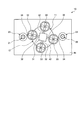
- FIG. 1 is a front view showing a flying object take-off and landing support apparatus of this embodiment.
- FIG. 2 is a plan view showing a flying object take-off and landing support apparatus.
- FIG. 3 is a schematic diagram showing the takeoff and landing operation of the flying object.
- FIG. 4 is a schematic diagram showing a flying object take-off and landing operation.
- FIG. 1 is a front view showing a flying object take-off and landing support apparatus according to the present embodiment
- FIG. 2 is a plan view showing the flying object take-off and landing support apparatus.
- a flying body having a rotating blade driven by a driving device such as a motor or an internal combustion engine
- the lift (effect) of the rotating blade increases or decreases the rotational speed of the rotating blade.
- the flying body that is adjusted (controlled) will be described.
- the flying object take-off and landing support device 10 automatically takes off and landing the flying object 11 with respect to the target point 12.
- the flying object take-off and landing support apparatus 10 is provided in the vicinity of the target point 12 and is parallel to each other (two in this embodiment) guide rods 21 and 22, and the flying object 11 is provided with a plurality of guides.
- a plurality of (two in this embodiment) guide rings 23 and 24 through which the rods 21 and 22 can be inserted are provided.
- the flying body 11 has a plurality of (four in this embodiment) rotor blades 33 connected to the outside of the main body 31 by connecting portions 32.
- Each rotor blade 33 is arranged at a predetermined interval in the circumferential direction, and can be rotated by a built-in drive device (motor or internal combustion engine) (not shown).
- the flying body 11 can ascend by obtaining lift by rotating the rotor blades 33. Further, the flying object 11 can be lowered with a reduced lift by lowering the rotational speed of each rotary wing 33. Further, the flying object 11 can move in the horizontal direction by changing the number of rotations of each rotary wing 33 to change the lift of each rotary wing 33 and tilting the posture.
- guide rings 23 and 24 are connected to the outside of two of the plurality of rotor blades 33 by connecting portions 34, respectively.
- the two rotor blades 33 to which the guide rings 23 and 24 are attached are arranged at opposing positions passing through the center of the flying object 11.
- the flying object 11 is provided with a plurality of leg portions 36 by connecting rods 35.
- a support plate 41 is installed on the upper surface, and a take-off / landing platform 42 serving as the target point 12 is provided on the support plate 41.
- the takeoff / landing platform 42 has a cylindrical shape, and a plurality of legs 36 of the flying object 11 can be landed.
- the support plate 41 has guide rods 21 and 22 erected on both sides of the takeoff / landing base 42. The two guide rods 21 and 22 are arranged at opposing positions passing through the center of the take-off and landing platform 42.
- the distance between the centers of the guide rods 21 and 22 and the distance between the centers of the guide rings 23 and 24 are set to the same distance. Therefore, the guide rings 23 and 24 provided on the flying object 11 can be inserted into the guide rods 21 and 22 provided on the support plate 41 on the ground G, respectively.
- the guide rods 21 and 22 have different overall lengths, and the guide rod 21 is longer than the guide rod 22.
- each guide rod 21, 22 is desirably set to a length up to a position where the flying object 11 is unlikely to receive a surface effect from the ground G.
- the surface effect of the flying object 11 from the ground G differs depending on the weight of the flying object 11 and the output of each rotary wing 33, but in this embodiment, for example, it is in the range of 30 cm to 5 m. ing.
- Each guide rod 21 and 22 has a tapered shape toward the tip.
- each guide rod 21, 22 has a conical shape, a lower end portion is fixed to the support plate 41, and has a tapered shape whose outer diameter decreases toward the upper end portion.
- the guide rings 23 and 24 on the side of the flying object 11 can be inserted into the guide rods 21 and 22 at the target point 12, but at the position where the flying object 11 is placed on the takeoff / landing platform 42.
- a gap is secured between the inner peripheral surfaces of 23 and 24 and the outer peripheral surfaces of the guide rods 21 and 22.
- the two guide rods 21 and 22 are arranged parallel to each other along the vertical direction from the support plate 41.
- two guide rods 21 and 22 and two guide rings 23 and 24 are provided. However, three or more may be provided.
- detectors 43 and 44 for detecting that the guide rings 23 and 24 have passed through the guide rods 21 and 22 are provided.
- Each detector 43, 44 is provided on the upper part of each guide rod 21, 22, and detects that each guide ring 23, 24 has passed.
- a target (for example, a plurality of LED lamps) 45 is provided on the upper surface of the takeoff / landing platform 42 to be the target point 12, while a detector (for example, a camera) capable of detecting the target 45 from the flying object 11 side. 46 is provided.
- the flying object take-off and landing support device 10 is applied to a flying device in which the flying object 11 takes off and landing with respect to the target point 12 on the ground G.
- the present invention is not limited to this configuration.
- the guide rods 21 and 22 may be provided on a moving body such as an automobile, a railway, and a ship, and the flying body 11 on which the guide rings 23 and 24 are provided with respect to the moving body may take off and land.
- the guide rods 21 and 22 are provided on the roof of a building such as a public building such as a hospital or a school, a condominium as a residence, a factory, a warehouse, etc., and the flying object 11 provided with guide rings 23 and 24 for the building.
- It may be a flying device that takes off and landing.
- a take-off and landing facility such as a heliport or a take-off and landing tower
- the adjustment mechanism is configured to allow the guide rods 21 and 22 to move in an amount proportional to the wind speed in the windward direction based on information from an anemometer (not shown) attached to the flying object 11. It is desirable to incline.
- the adjustment mechanism is adjusted so that the plurality of guide rods 21 and 22 are maintained along the vertical direction, or the tip portion is adjusted to be inclined in an amount proportional to the wind speed in the windward direction,
- the distance between the centers of the plurality of guide rods 21 and 22 and the distance between the centers of the plurality of guide rings 23 and 24 are maintained to be the same distance.
- the support plate 41 is also tilted together, and the interval (distance) between the plurality of guide rods 21 and 22 is also adjusted.
- the rotating object 33 is lowered to the main body 31 by lowering the rotation of each rotating wing 33 from the state where the flying object 11 is released from the restraint from the guide rods 21 and 22.
- the generated lift decreases and the flying object 11 is lowered.
- a detector (camera) 46 provided on the flying object 11 detects a target object (LED lamp) 45 on the upper surface of the take-off / landing platform 42 that becomes the target point 12 and performs image processing on the detection result.
- the position of the flying object 11 in the horizontal direction with respect to the target point 12 is recognized from the position and shape of the image, and the positions of the guide rings 23 and 24 in the circumferential direction with respect to the guide rods 21 and 22 are recognized.
- the attitude of the flying object 11 is controlled so that the main body 31 is located above the target point 12 and the guide rings 23 and 24 are located above the guide rods 21 and 22, the attitude is maintained. And descends downward B in the vertical direction. Then, as shown by a two-dot chain line in FIG. 4, the flying body 11 is restrained from moving in the horizontal direction by inserting the guide rods 21 and 22 into the guide rings 23 and 24. At this time, the flying object 11 is first inserted into the long guide rod 21 by the guide ring 23 to restrain the movement in the linear direction in the horizontal direction, and then the guide ring 24 is inserted into the guide rod 22 in the horizontal direction. Circumferential movement is restricted.
- the flying object 11 descends with the guide rods 21 and 22 being inserted into the guide rings 23 and 24 and restrained in the horizontal direction, and as shown in FIG.
- the rotating blades 33 are stopped while rotating.
- the flying body 11 is restrained by the guide rods 21 and 22 via the guide rings 23 and 24, and then descends while being guided by the guide rods 21 and 22, and the take-off and landing platform 42 that becomes the target point 12. Placed on top.
- the flying object take-off and landing support device of the present embodiment is the flying object take-off and landing support device 10 that takes off and landing the flying object 11 having the rotary wing 33 with respect to the target point 12.
- the plurality of guide rods 21 and 22 that are parallel to each other and the plurality of guide rings 23 and 24 that are provided at the target point 12 and into which the plurality of guide rods 21 and 22 can be inserted are provided. And the center distance between the plurality of guide rings 23 and 24 are set to the same distance.
- the plurality of guide rods 21 and 22 are inserted into the plurality of guide rings 23 and 24, so that the horizontal movement of the flying object 11 is prevented. Even when affected by changes in the surrounding environment and surface effects, the horizontal posture is prevented from being disturbed, and the flying object 11 can be landed and landed at the target point 12 easily and stably.
- the plurality of guide rods 21 and 22 have different overall lengths. Therefore, when the flying object 11 lands at the target point 12, the guide rings 23 and 24 are inserted and restrained in order by the guide rods 21 and 22 having different lengths, and the guide rings 23 and 24 are connected to the guide rings 23 and 24, respectively.
- the guide rods 21 and 22 can be easily inserted, and the flying object 11 can be easily maintained in a horizontal state.
- each guide rod 21 and 22 is tapered toward the tip. Therefore, the guide rings 23 and 24 can be easily inserted into the guide rods 21 and 22.
- the flying object take-off and landing support apparatus of the present embodiment is provided with detectors 43 and 44 that detect that the guide rings 23 and 24 have passed through the guide rods 21 and 22. Therefore, the detectors 43 and 44 recognize the restraint and release of the flying object 11 in the horizontal direction with respect to the guide rods 21 and 22 in order to detect that the guide rods 21 and 22 have passed through the guide rings 23 and 24. And the output of the flying object 11 can be adjusted appropriately.
- a plurality of guide rods 21 and 22 are provided at least three. Accordingly, the flying object 11 is restrained by three or more horizontal movements by the guide rods 21 and 22, so that the flying object 11 can be guided in a stable posture.
- a target object 45 that can be detected from the detector 46 of the flying object 11 is provided at the target point 12. Therefore, the flying object 11 is landed while detecting the target 45 provided at the target point 12, and the flying object 11 can be landed with high accuracy with respect to the target point 12.
- a plurality of guide rings 23 and 24 are arranged outside the rotor wing 33. Therefore, interference between the rotary wing 33 and the guide rods 21 and 22 when the flying object 11 takes off and landing can be suppressed.
- a plurality of guide rods 21 and 22 are arranged at the target point 12 along the vertical direction. Therefore, the guide rods 21 and 22 can be easily inserted into the guide rings 23 and 24 by moving the flying object 11 along the vertical direction.
- an adjustment mechanism for maintaining the plurality of guide rods 21 and 22 along the vertical direction is provided. Therefore, when the side on which the guide rods 21 and 22 are installed is a moving body, the guide rods 21 and 22 can always be maintained along the vertical direction by the adjustment mechanism, and the guide rods 23 and 24 can be easily guided by the guide rods. 21 and 22 can be inserted.
- the adjustment mechanism has a plurality of guide rods 21 and 22 that wind at the tip part based on information from an anemometer (not shown) attached to the flying object 11. It can be greatly tilted upward as the wind speed increases. Therefore, the guide rods 21 and 22 can be easily inserted into the guide rings 23 and 24 when the flying object 11 is landed from a state where it is hovered by tilting it in the windward direction.
- the adjustment mechanism is adjusted so that the plurality of guide rods 21 and 22 are maintained along the vertical direction, or the tip portion is adjusted to be inclined in an amount proportional to the wind speed in the windward direction.
- the distance between the centers of the plurality of guide rods 21 and 22 and the distance between the centers of the plurality of guide rings 23 and 24 are maintained to be the same distance.
- the flying device of the present embodiment includes the flying object 11 having the rotary wing 33 and the flying object take-off and landing support device 10. Therefore, when the flying object 11 is taken off and landing using the flying object take-off and landing support device 10, the plurality of guide rods 21 and 22 are inserted into the plurality of guide rings 23 and 24, so that the flying object 11 can be easily and It is possible to stably take off and land at the target point 12.
- a plurality of guide rods 21 and 22 are provided on the moving body, and a plurality of guide rings 23 and 24 are provided on the flying body 11. Therefore, the flying object 11 can be taken off and landed on the moving object by the guide rings 23 and 24, and the flying device can be moved to a desired place and used.
- a plurality of guide rods 21 and 22 are provided in the building, and a plurality of guide rings 23 and 24 are provided in the flying body 11. Therefore, the flying object 11 can be taken off and landing on the building by the guide rings 23 and 24. For example, the flying object 11 can easily carry the cargo.
- the guide rods 21 and 22 are provided at the target point 12 and the guide rings 23 and 24 are provided at the flying object 11.
- the guide ring is provided at the target point 12 and the guide rod is provided at the flying object 11. It may be provided.
- the flying object 11 is configured to be placed on the takeoff / landing platform 42.
- the flying object 11 may be configured to be placed on the support plate 41 or the ground G.
- stepped portions of the guide rods 21 and 22 may be provided so that the guide rings 23 and 24 of the flying object 11 abut on the stepped portions of the guide rods 21 and 22.
- the detector (camera) 46 provided on the flying object 11 detects the target (LED lamp) 45 on the upper surface of the take-off / landing platform 42 as the target point 12, and the attitude of the flying object 11 is determined.
- the present invention is not limited to this configuration.
- a transmitter and a receiver that transmit and receive the position signal between the flying object 11 and the target point 12 may be provided, and the flying object 11 may land on the target point 12 according to the position signal.
- GPS may be mounted on the flying object 11 and the flying object 11 may be landed on the target point 12 according to the GPS detection result.
- the flying object takeoff and landing support apparatus 10 has been described as automatically taking off and landing the flying object 11 at the target point 12. However, the flying object 11 manually takes off and landing at the target point 12. You may apply to.
Abstract
飛行体の離着陸支援装置及び飛行装置において、回転翼(33)を有する飛行体(11)を目標地点(12)に対して離着陸させる飛行体(11)の離着陸支援装置(10)とし、飛行体(11)に設けられて互いに平行をなす複数のガイドロッド(21,22)と、目標地点(12)に設けられて複数のガイドロッド(21,22)が挿通可能な複数のガイドリング(23,24)とを備え、複数のガイドロッド(21,22)の中心間距離と複数のガイドリング(23,24)の中心間距離とを同距離に設定することで、飛行体の安定した離着陸を可能とする。
Description
本発明は、飛行体の離陸動作及び着陸動作を支援するための飛行体の離着陸支援装置及び飛行装置に関するものである。
回転翼を有する飛行体は、回転翼の回転数を上げたり、回転翼ピッチ角を立てる(回転翼の揚力が大きくなる方向へピッチ角を傾ける)ことで飛行体を上昇させ、回転数を下げたり、回転翼ピッチ角を寝かせる(回転翼の揚力が小さくなる方向へピッチ角を傾ける)ことで飛行体を下降させる。特に、無人の飛行体の場合は、駆動装置(モータまたは内燃機関など)により駆動する回転翼を有しており、ユーザが自動または手動により無線回線または有線回線を用いてこの駆動装置を駆動制御したり、回転翼のピッチ角を制御したりしている。
このような技術として、例えば、下記特許文献1に記載されたものがある。
飛行体を着陸させるときは、駆動装置を駆動制御して回転翼の回転数を下げることで飛行体を下降させ、地面に着地させる。このとき、飛行体は、回転翼の回転数を下げて低速で下降することから、回転翼の揚力が小さくなるために着地直前は姿勢を制御しにくく、不安定な状態となる。そのため、飛行体は、着地直前に風などの環境変化の影響を受けやすく、安定した姿勢での着地が困難となる。また、飛行体は、着地時、回転翼と地面との間の空気流の変化の影響を受ける、所謂、表面効果の影響を受け、この場合であっても、安定した姿勢での着地が困難となる。
本発明は上述した課題を解決するものであり、飛行体の安定した離着陸を可能とする飛行体の離着陸支援装置及び飛行装置を提供することを目的とする。
上述の目的を達成するための本発明の飛行体の離着陸支援装置は、回転翼を有する飛行体を目標地点に対して離着陸させる飛行体の離着陸支援装置であって、前記飛行体と前記目標地点のいずれか一方に設けられて互いに平行をなす複数のガイドロッドと、前記飛行体と前記目標地点のいずれか他方に設けられて前記複数のガイドロッドが挿通可能な複数のガイドリングと、を備え、前記複数のガイドロッドの中心間距離と前記複数のガイドリングの中心間距離とが同距離に設定される、ことを特徴とするものである。
従って、飛行体の離着陸時に、複数のガイドロッドが複数のガイドリングに挿通することで、飛行体が周辺の環境の変化の影響や表面効果の影響を受けても、姿勢が乱れることが抑制され、飛行体を容易に、且つ、安定して目標地点に離着陸させることができる。
本発明の飛行体の離着陸支援装置では、前記複数のガイドロッドは、全長が相違することを特徴としている。
従って、飛行体が目標地点に着陸するとき、各ガイドリングが長さの異なる各ガイドロッドに順に挿通されることとなり、各ガイドリングを各ガイドロッドに容易に挿通させることができる。
本発明の飛行体の離着陸支援装置では、前記複数のガイドロッドは、先端部に向けて先細形状をなすことを特徴としている。
従って、各ガイドロッドの先端部を先細形状とすることで、各ガイドリングを各ガイドロッドに容易に挿通させることができる。
本発明の飛行体の離着陸支援装置では、前記ガイドリングが前記ガイドロッドに通過されたことを検出する検出器が設けられることを特徴としている。
従って、検出器は、ガイドリングにガイドロッドに通過されたことを検出するため、ガイドロッドに対する飛行体の水平方向における拘束及び解除を認識することができ、飛行体の出力を適正に調整することができる。
本発明の飛行体の離着陸支援装置では、前記複数のガイドロッドは、3個以上設けられることを特徴としている。
従って、飛行体は、各ガイドロッドにより水平方向の移動が3か所以上で拘束されることとなり、飛行体を安定した姿勢でガイドすることができる。
本発明の飛行体の離着陸支援装置では、前記目標地点に前記飛行体側から検出可能な目標物が設けられることを特徴としている。
従って、飛行体は、目標地点に設けられた目標物を検出しながら着陸することとなり、飛行体を目標地点に対して高精度に着地させることができる。
本発明の飛行体の離着陸支援装置では、前記回転翼の外側に前記複数のガイドロッドまたは前記複数のガイドリングが配置されることを特徴としている。
従って、回転翼の外側にガイドロッドまたはガイドリングが配置されることで、回転翼とガイドロッドまたはガイドリングとの干渉を抑制することができる。
本発明の飛行体の離着陸支援装置では、前記複数のガイドロッドは、前記目標地点に鉛直方向に沿って配置されることを特徴としている。
従って、ガイドロッドを目標地点に鉛直方向に沿って配置することで、飛行体を鉛直方向に沿って移動することで、容易にガイドリングにガイドロッドを挿通させることができる。
本発明の飛行体の離着陸支援装置では、前記複数のガイドロッドを鉛直方向に沿って維持する調整機構が設けられることを特徴としている。
従って、各ガイドロッドを設置する側が移動体であるとき、調整機構により各ガイドロッドを常時鉛直方向に沿って維持することができ、ガイドリングに容易にガイドロッドを挿通させることができる。
本発明の飛行体の離着陸支援装置では、前記調整機構は、風向風速計の情報に基づいて前記複数のガイドロッドを先端部が風上方向へ風速の増加に伴って大きく傾斜させることを特徴としている。
従って、飛行体を風上方向へ傾けることでホバリングさせた状態から着陸させるとき、ガイドリングに容易にガイドロッドを挿通させることができる。
また、本発明の飛行装置は、回転翼を有する飛行体と、前記飛行体の離着陸支援装置と、を備えることを特徴とするものである。
従って、飛行体を離着陸支援装置を用いて離着陸させるとき、複数のガイドロッドが複数のガイドリングに挿通することで、飛行体を容易に、且つ、安定して目標地点に離着陸させることができる。
本発明の飛行装置では、前記複数のガイドロッドが移動体に設けられ、前記複数のガイドリングが前記飛行体に設けられることを特徴としている。
従って、ガイドロッドを移動体に設け、飛行体をガイドリングにより移動体に対して離着陸させることができ、飛行装置を所望の場所に移動して使用することができる。
本発明の飛行装置では、前記複数のガイドロッドが建物に設けられ、前記複数のガイドリングが前記飛行体に設けられることを特徴としている。
従って、ガイドロッドを建屋に設け、飛行体をガイドリングにより建屋に対して離着陸させることができ、例えば、飛行体により容易に荷物の搬送を行うことができる。
本発明の飛行体の離着陸支援装置及び飛行装置によれば、飛行体と目標地点のいずれか一方に複数のガイドロッドを設け、他方に複数のガイドリングを設けるので、飛行体の離着陸時に、複数のガイドロッドが複数のガイドリングに挿通することで、飛行体を容易に、且つ、安定して目標地点に離着陸させることができる。
以下に添付図面を参照して、本発明に係る飛行体の離着陸支援装置及び飛行装置の好適な実施形態を詳細に説明する。なお、この実施形態により本発明が限定されるものではなく、また、実施形態が複数ある場合には、各実施形態を組み合わせて構成するものも含むものである。
図1は、本実施形態の飛行体の離着陸支援装置を表す正面図、図2は、飛行体の離着陸支援装置を表す平面図である。なお、ここでは、説明の1例として、モータや内燃機関な度の駆動装置により駆動する回転翼を有する飛行体について記載し、回転翼の揚力(効果)は、回転翼の回転数を上げ下げすることで調整(制御)している飛行体について説明する。
本実施形態において、図1及び図2に示すように、飛行体の離着陸支援装置10は、飛行体11を目標地点12に対して自動的に離着陸させるものである。飛行体の離着陸支援装置10は、目標地点12の近傍に設けられて互いに平行をなす複数(本実施形態では、2個)のガイドロッド21,22と、飛行体11に設けられて複数のガイドロッド21,22が挿通可能な複数(本実施形態では、2個)のガイドリング23,24とを備えている。
飛行体11は、本体31の外側に連結部32により複数(本実施形態では、4個)の回転翼33が連結されている。各回転翼33は、周方向に所定間隔を空けて配置され、内蔵された駆動装置(モータまたは内燃機関など)(図示略)により回転可能となっている。飛行体11は、各回転翼33を回転することで、揚力を得て上昇することができる。また、飛行体11は、各回転翼33の回転数を下げることで、揚力を少なくして下降することができる。更に、飛行体11は、各回転翼33の回転数を変えることで、各回転翼33の揚力を変えて姿勢を傾けて水平方向に移動することができる。
飛行体11は、複数の回転翼33のうちの2個の回転翼33の外側に連結部34によりガイドリング23,24がそれぞれ連結されている。各ガイドリング23,24が取付けられる2個の回転翼33は、飛行体11の中心を通る対向位置に配置されている。また、飛行体11は、連結ロッド35により複数の脚部36が設けられている。
一方、地面Gは、上面に支持板41が設置され、支持板41上に目標地点12となる離着陸台42が設けられている。この離着陸台42は、円柱形状をなし、飛行体11の複数の脚部36が着地可能となっている。また、支持板41は、離着陸台42の両側にガイドロッド21,22がそれぞれ立設されている。この2個のガイドロッド21,22は、離着陸台42の中心を通る対向位置に配置されている。
各ガイドロッド21,22の中心間距離と、各ガイドリング23,24の中心間距離とは、同距離に設定されている。そのため、飛行体11に設けられた各ガイドリング23,24が、地面Gの支持板41に設けられた各ガイドロッド21,22にそれぞれ挿通可能となる。
各ガイドロッド21,22は、全長が相違しており、ガイドロッド21がガイドロッド22よりも長くなっている。この場合、各ガイドロッド21,22は、飛行体11が地面Gからの表面効果を受けにくい位置までの長さに設定することが望ましい。この場合、飛行体11の地面Gからの表面効果は、飛行体11の重量や各回転翼33による出力などにより相違するものであるが、本実施形態では、例えば、30cmから5mの範囲となっている。また、各ガイドロッド21,22は、先端部に向けて先細形状をなしている。即ち、各ガイドロッド21,22は、円錐形状をなし、下端部が支持板41に固定され、上端部に向けて外径が小さくなる先細形状となっている。そして、飛行体11側の各ガイドリング23,24は、目標地点12の各ガイドロッド21,22に挿通可能であるが、飛行体11が離着陸台42上に載置された位置で、ガイドリング23,24の内周面とガイドロッド21,22の外周面との間に隙間が確保される。
この2個のガイドロッド21,22は、支持板41から鉛直方向に沿って互いに平行をなして配置されている、本実施形態では、ガイドロッド21,22とガイドリング23,24をそれぞれ2個ずつ設けたが、3個以上設けてもよい。
また、各ガイドリング23,24が各ガイドロッド21,22に通過されたことを検出する検出器43,44が設けられている。各検出器43,44は、各ガイドロッド21,22の上部に設けられており、各ガイドリング23,24が通過したことを検出する。更に、目標地点12となる離着陸台42の上面に目標物(例えば、複数のLEDランプなど)45が設けられる一方、飛行体11側から目標物45を検出可能な検出器(例えば、カメラなど)46が設けられている。
なお、本実施形態では、飛行体の離着陸支援装置10を、地面Gの目標地点12に対して飛行体11が離着陸する飛行装置に適用したが、この構成に限定されるものではない。例えば、ガイドロッド21,22を自動車、鉄道、船舶などの移動体に設け、この移動体に対してガイドリング23,24が設けられた飛行体11が離着陸する飛行装置としてもよい。また、ガイドロッド21,22を病院や学校などの公共のビル、住宅としてのマンション、工場、倉庫などの建屋の屋上に設け、この建屋に対してガイドリング23,24が設けられた飛行体11が離着陸する飛行装置としてもよい。この場合、建物の屋上以外に、ベランダ、廊下、または、敷地内に設置した離着陸用設備(ヘリポート、離着陸用タワーなど)に複数のガイドロッド21,22を設けることが望ましい。
また、ガイドロッド21,22を移動体に設けた場合、各ガイドロッド21,22を鉛直方向に沿って維持する調整機構を設けることが望ましい。更に、このとき、調整機構は、飛行体11に装着された風向風速計(図示略)の情報に基づいて、複数のガイドロッド21,22を先端部が風上方向へ風速に比例した量だけ傾斜させることが望ましい。そして、調整機構により複数のガイドロッド21,22が鉛直方向に沿って維持するように調整したり、先端部が風上方向へ風速に比例した量だけ傾斜させるように調整したりしても、複数のガイドロッド21,22の中心間距離と複数のガイドリング23,24の中心間距離とが同距離になるように維持する。具体的には、調整機構により複数のガイドロッド21,22の角度を調整するとき、支持板41も一緒に傾斜させたり、複数のガイドロッド21,22の間隔(距離)も調整したりする。
ここで、本実施形態の飛行体の離着陸支援装置10による飛行体の離着陸方法について説明する。
飛行体11が離陸する場合、図1に示すように、飛行体11が目標地点12となる離着陸台42上に載置された状態から、各回転翼33を駆動回転すると、本体31に揚力が発生し、この飛行体11が上昇する。このとき、飛行体11は、図3に示すように、各ガイドリング23,24に各ガイドロッド21,22が挿通して水平方向の移動が拘束されていることから、各ガイドロッド21,22に沿って鉛直方向の上方Aに向けて上昇する。そして、図4に二点鎖線で示すように、各検出器43,44が各ガイドリング23,24を検出すると、所定時間後に、飛行体11の各ガイドリング23,24が各ガイドロッド21,22から抜け出ることが確認され、飛行体11は、図4に実線で示すように、各ガイドロッド21,22からの拘束が外れて所望の方向に飛行する。
一方、飛行体11が着陸する場合、図4に示すように、飛行体11が各ガイドロッド21,22からの拘束が外れて飛行する状態から、各回転翼33の回転を下げて本体31に発生する揚力が低下し、飛行体11を下降させる。このとき、飛行体11に設けられた検出器(カメラ)46が目標地点12となる離着陸台42の上面の目標物(LEDランプ)45を検出し、検出結果を画像処理する。そして、画像の位置と形状から、目標地点12に対する飛行体11の水平方向における位置を認識すると共に、各ガイドロッド21,22に対する各ガイドリング23,24の周方向における位置を認識する。
そして、飛行体11は、本体31が目標地点12の上方で、且つ、各ガイドリング23,24が各ガイドロッド21,22の上方に位置するように姿勢を制御すると、その姿勢を維持したままで鉛直方向の下方Bに向けて下降する。すると、飛行体11は、図4に二点鎖線で示すように、各ガイドリング23,24に各ガイドロッド21,22が挿通されて水平方向の移動が拘束される。このとき、飛行体11は、まず、ガイドリング23が長いガイドロッド21に挿通して水平方向における直線方向の移動が拘束され、次に、ガイドリング24がガイドロッド22に挿通して水平方向における周方向の移動が拘束される。
そして、飛行体11は、各ガイドリング23,24に各ガイドロッド21,22が挿通されて水平方向の移動が拘束されて下降し、図3に示すように、各検出器43,44が各ガイドリング23,24を検出すると、各回転翼33の回転を下げながら停止する。すると、飛行体11は、各ガイドリング23,24を介して各ガイドロッド21,22に拘束されることで、各ガイドロッド21,22にガイドされながら下降し、目標地点12となる離着陸台42上に載置される。
このように本実施形態の飛行体の離着陸支援装置にあっては、回転翼33を有する飛行体11を目標地点12に対して離着陸させる飛行体の離着陸支援装置10とし、飛行体11に設けられて互いに平行をなす複数のガイドロッド21,22と、目標地点12に設けられて複数のガイドロッド21,22が挿通可能な複数のガイドリング23,24とを備え、複数のガイドロッド21,22の中心間距離と複数のガイドリング23,24の中心間距離とを同距離に設定する。
従って、飛行体11の離着陸時に、複数のガイドロッド21,22が複数のガイドリング23,24に挿通することで、飛行体11における水平方向の移動が阻止されることとなり、飛行体11は、周辺の環境の変化の影響や表面効果の影響を受けても、水平姿勢が乱れることが抑制され、飛行体11を容易に、且つ、安定して目標地点12に離着陸させることができる。
本実施形態の飛行体の離着陸支援装置では、複数のガイドロッド21,22の全長を相違させている。従って、飛行体11が目標地点12に着陸するとき、各ガイドリング23,24が長さの異なる各ガイドロッド21,22に順に挿通されて拘束されることとなり、各ガイドリング23,24を各ガイドロッド21,22に容易に挿通させることができると共に、飛行体11を容易に水平状態に維持することができる。
本実施形態の飛行体の離着陸支援装置では、各ガイドロッド21,22を先端部に向けて先細形状としている。従って、各ガイドリング23,24を各ガイドロッド21,22に容易に挿通させることができる。
本実施形態の飛行体の離着陸支援装置では、ガイドリング23,24がガイドロッド21,22に通過されたことを検出する検出器43,44を設けている。従って、検出器43,44は、ガイドリング23,24にガイドロッド21,22が通過されたことを検出するため、ガイドロッド21,22に対する飛行体11の水平方向における拘束及び解除を認識することができ、飛行体11の出力を適正に調整することができる。
本実施形態の飛行体の離着陸支援装置では、複数のガイドロッド21,22を3個以上設けている。従って、飛行体11は、各ガイドロッド21,22により水平方向の移動が3か所以上で拘束されることとなり、飛行体11を安定した姿勢でガイドすることができる。
本実施形態の飛行体の離着陸支援装置では、目標地点12に飛行体11の検出器46から検出可能な目標物45を設けている。従って、飛行体11は、目標地点12に設けられた目標物45を検出しながら着陸することとなり、飛行体11を目標地点12に対して高精度に着地させることができる。
本実施形態の飛行体の離着陸支援装置では、回転翼33の外側に複数のガイドリング23,24を配置している。従って、飛行体11の離着陸時における回転翼33とガイドロッド21,22との干渉を抑制することができる。
本実施形態の飛行体の離着陸支援装置では、複数のガイドロッド21,22を目標地点12に鉛直方向に沿って配置している。従って、飛行体11を鉛直方向に沿って移動することで、容易にガイドリング23,24にガイドロッド21,22を挿通させることができる。
本実施形態の飛行体の離着陸支援装置では、複数のガイドロッド21,22を鉛直方向に沿って維持する調整機構を設けている。従って、各ガイドロッド21,22を設置する側が移動体であるとき、調整機構により各ガイドロッド21,22を常時鉛直方向に沿って維持することができ、ガイドリング23,24に容易にガイドロッド21,22を挿通させることができる。
また、本実施形態の飛行体の離着陸支援装置では、調整機構は、飛行体11に装着された風向風速計(図示略)の情報に基づいて、複数のガイドロッド21,22を先端部が風上方向へ風速の増加に伴って大きく傾斜させることができる。そのため、飛行体11を風上方向へ傾けることでホバリングさせた状態から着陸させるとき、ガイドリング23,24に容易にガイドロッド21,22を挿通させることができる。
このとき、調整機構により複数のガイドロッド21,22が鉛直方向に沿って維持するように調整したり、先端部が風上方向へ風速に比例した量だけ傾斜させるように調整したりしても、複数のガイドロッド21,22の中心間距離と複数のガイドリング23,24の中心間距離とが同距離になるように維持する。
また、本実施形態の飛行装置にあっては、回転翼33を有する飛行体11と、飛行体の離着陸支援装置10とを備えている。従って、飛行体11を飛行体の離着陸支援装置10を用いて離着陸させるとき、複数のガイドロッド21,22が複数のガイドリング23,24に挿通することで、飛行体11を容易に、且つ、安定して目標地点12に離着陸させることができる。
本実施形態の飛行装置にあっては、複数のガイドロッド21,22を移動体に設け、複数のガイドリング23,24を飛行体11に設けている。従って、飛行体11をガイドリング23,24により移動体に対して離着陸させることができ、飛行装置を所望の場所に移動して使用することができる。
本実施形態の飛行装置にあっては、複数のガイドロッド21,22を建物に設け、複数のガイドリング23,24を飛行体11に設けている。従って、飛行体11をガイドリング23,24により建屋に対して離着陸させることができ、例えば、飛行体11により容易に荷物の搬送を行うことができる。
なお、上述した実施形態では、目標地点12にガイドロッド21,22を設け、飛行体11にガイドリング23,24を設けたが、目標地点12にガイドリングを設け、飛行体11にガイドロッドを設けてもよい。
また、上述した実施形態では、飛行体11を離着陸台42上に載置するように構成したが、支持板41や地面G上に載置するように構成してもよい。更に、ガイドロッド21,22の段付き部を設け、飛行体11のガイドリング23,24が、ガイドロッド21,22の段付き部に当接するように構成してもよい。
また、上述した実施形態では、飛行体11に設けられた検出器(カメラ)46が目標地点12となる離着陸台42の上面の目標物(LEDランプ)45を検出し、飛行体11の姿勢を制御するように構成したが、この構成に限定されるものではない。例えば、飛行体11と目標地点12との間でその位置信号を送受信する送信機と受信機を設け、この位置信号に応じて飛行体11を目標地点12に着陸させてもよい。また、飛行体11にGPSを搭載し、GPSの検出結果に応じて飛行体11を目標地点12に着陸させてもよい。
また、上述した実施形態にて、飛行体の離着陸支援装置10は、飛行体11を目標地点12に自動的に離着陸させるものとして説明したが、飛行体11を目標地点12に手動で離着陸させるものに適用してもよい。
10 飛行体の離着陸支援装置
11 飛行体
12 目標地点
21,22 ガイドロッド
23,24 ガイドリング
31 本体
33 回転翼
36 脚部
41 支持板
42 離着陸台
43,44 検出器
45 目標物
46 検出器
G 地面
11 飛行体
12 目標地点
21,22 ガイドロッド
23,24 ガイドリング
31 本体
33 回転翼
36 脚部
41 支持板
42 離着陸台
43,44 検出器
45 目標物
46 検出器
G 地面
Claims (13)
- 回転翼を有する飛行体を目標地点に対して離着陸させる飛行体の離着陸支援装置であって、
前記飛行体と前記目標地点のいずれか一方に設けられて互いに平行をなす複数のガイドロッドと、
前記飛行体と前記目標地点のいずれか他方に設けられて前記複数のガイドロッドが挿通可能な複数のガイドリングと、
を備え、
前記複数のガイドロッドの中心間距離と前記複数のガイドリングの中心間距離とが同距離に設定される、
ことを特徴とする飛行体の離着陸支援装置。 - 前記複数のガイドロッドは、全長が相違することを特徴とする請求項1に記載の飛行体の離着陸支援装置。
- 前記複数のガイドロッドは、先端部に向けて先細形状をなすことを特徴とする請求項1または請求項2に記載の飛行体の離着陸支援装置。
- 前記ガイドリングが前記ガイドロッドに通過されたことを検出する検出器が設けられることを特徴とする請求項1から請求項3のいずれか一項に記載の飛行体の離着陸支援装置。
- 前記複数のガイドロッドは、3個以上設けられることを特徴とする請求項1から請求項4のいずれか一項に記載の飛行体の離着陸支援装置。
- 前記目標地点に前記飛行体側から検出可能な目標物が設けられることを特徴とする請求項1から請求項5のいずれか一項に記載の飛行体の離着陸支援装置。
- 前記回転翼の外側に前記複数のガイドロッドまたは前記複数のガイドリングが配置されることを特徴とする請求項1から請求項6のいずれか一項に記載の飛行体の離着陸支援装置。
- 前記複数のガイドロッドは、前記目標地点に鉛直方向に沿って配置されることを特徴とする請求項1から請求項7のいずれか一項に記載の飛行体の離着陸支援装置。
- 前記複数のガイドロッドを鉛直方向に沿って維持する調整機構が設けられることを特徴とする請求項8に記載の飛行体の離着陸支援装置。
- 前記調整機構は、風向風速計の情報に基づいて前記複数のガイドロッドを先端部が風上方向へ風速の増加に伴って大きく傾斜させることを特徴とする請求項9に記載の飛行体の離着陸支援装置。
- 回転翼を有する飛行体と、
請求項1から請求項10のいずれか一項に記載の飛行体の離着陸支援装置と、
を備えることを特徴とする飛行装置。 - 前記複数のガイドロッドが移動体に設けられ、前記複数のガイドリングが前記飛行体に設けられることを特徴とする請求項11に記載の飛行装置。
- 前記複数のガイドロッドが建物に設けられ、前記複数のガイドリングが前記飛行体に設けられることを特徴とする請求項11に記載の飛行装置。
Priority Applications (2)
| Application Number | Priority Date | Filing Date | Title |
|---|---|---|---|
| EP16891641.9A EP3421376B1 (en) | 2016-02-26 | 2016-12-02 | Flying body take-off and landing assistance device |
| US16/063,923 US11046456B2 (en) | 2016-02-26 | 2016-12-02 | Takeoff and landing assist apparatus for flight vehicle, and flight device |
Applications Claiming Priority (2)
| Application Number | Priority Date | Filing Date | Title |
|---|---|---|---|
| JP2016036328A JP6691794B2 (ja) | 2016-02-26 | 2016-02-26 | 飛行体の離着陸支援装置及び飛行装置 |
| JP2016-036328 | 2016-02-26 |
Publications (1)
| Publication Number | Publication Date |
|---|---|
| WO2017145485A1 true WO2017145485A1 (ja) | 2017-08-31 |
Family
ID=59686177
Family Applications (1)
| Application Number | Title | Priority Date | Filing Date |
|---|---|---|---|
| PCT/JP2016/085911 WO2017145485A1 (ja) | 2016-02-26 | 2016-12-02 | 飛行体の離着陸支援装置及び飛行装置 |
Country Status (4)
| Country | Link |
|---|---|
| US (1) | US11046456B2 (ja) |
| EP (1) | EP3421376B1 (ja) |
| JP (1) | JP6691794B2 (ja) |
| WO (1) | WO2017145485A1 (ja) |
Cited By (1)
| Publication number | Priority date | Publication date | Assignee | Title |
|---|---|---|---|---|
| US11459100B2 (en) * | 2016-12-13 | 2022-10-04 | Korea Aerospace Research Institute | Drone takeoff and landing system |
Families Citing this family (3)
| Publication number | Priority date | Publication date | Assignee | Title |
|---|---|---|---|---|
| DE102018101315A1 (de) * | 2018-01-22 | 2019-07-25 | Deutsche Post Ag | Anordnung und Verfahren mit einer flugfähigen unbemannten Transporteinrichtung |
| US11932424B2 (en) * | 2019-08-12 | 2024-03-19 | Roman Nawojczyk | Utter system for multiple use of the space-rockets equipped with spreadable-arms and possibly more devices, and method of these space-rockets vertical landing by hanging on landing-station having movable gantries and more apparatus |
| US20210387744A1 (en) * | 2020-01-08 | 2021-12-16 | Iron Drone Ltd. | Unmanned aerial vehicle (uav) launching assembly for monitored and stable launching of uavs |
Citations (3)
| Publication number | Priority date | Publication date | Assignee | Title |
|---|---|---|---|---|
| JP2010179914A (ja) * | 2009-02-03 | 2010-08-19 | Honeywell Internatl Inc | 変容式無人航空/陸上ビークル |
| JP2011230756A (ja) * | 2010-04-27 | 2011-11-17 | Honeywell Internatl Inc | 地上近接性センサ |
| JP2015182744A (ja) * | 2014-03-26 | 2015-10-22 | 保俊 横山 | 固定ピッチ式の同軸2重反転型ヘリコプタ |
Family Cites Families (14)
| Publication number | Priority date | Publication date | Assignee | Title |
|---|---|---|---|---|
| DE2658483C3 (de) * | 1976-12-23 | 1981-10-22 | Messerschmitt-Bölkow-Blohm GmbH, 8000 München | Anlage zum Verzurren eines Fluggerätes, insbesondere eines Hubschraubers |
| US8453966B2 (en) * | 2009-02-12 | 2013-06-04 | Aerovel Corporation | Method and apparatus for automated launch, retrieval, and servicing of a hovering aircraft |
| DE102013004881A1 (de) * | 2013-03-07 | 2014-09-11 | Daniel Dirks | Lande- und (Akku-)Aufladestation - mit Kontakt oder kontaktlos - für einzelne oder mehrere im Verbund ferngesteuerte oder autonom fliegende Drohnen mit Drehflügeln (UAVs/Flugroboter/Multikopter) |
| KR101524936B1 (ko) * | 2013-10-21 | 2015-06-10 | 한국항공우주연구원 | 수직무인이착륙 비행체의 충전 및 격납을 위한 운송체 및 그 방법 |
| KR101842031B1 (ko) * | 2013-12-11 | 2018-03-26 | 한화테크윈 주식회사 | 감시 시스템 |
| CN105979837B (zh) * | 2014-01-23 | 2018-09-18 | 瓦斯菲·阿希达法特 | 用于建物正面清理装置的安全/稳定工具 |
| WO2015195175A2 (en) * | 2014-03-21 | 2015-12-23 | Borko Brandon | System for automatic takeoff and landing by interception of small uavs |
| US9499265B2 (en) | 2014-07-02 | 2016-11-22 | Skycatch, Inc. | Unmanned aerial vehicle landing interface |
| CN106715265B (zh) * | 2014-08-05 | 2019-08-16 | 意大利电信股份公司 | 无人飞行器起降平台 |
| CN113232547B (zh) * | 2014-08-08 | 2023-07-18 | 深圳市大疆创新科技有限公司 | 无人飞行器电池更换系统及方法 |
| WO2016137982A1 (en) * | 2015-02-24 | 2016-09-01 | Airogistic, L.L.C. | Methods and apparatus for unmanned aerial vehicle landing and launch |
| BR112018004732B1 (pt) * | 2015-09-11 | 2023-03-07 | Reese Alexander Mozer | Estação de docagem |
| KR101874204B1 (ko) * | 2016-12-13 | 2018-07-03 | 한국항공우주연구원 | 드론 착륙 시스템 |
| CN109896035A (zh) * | 2019-02-02 | 2019-06-18 | 南京航空航天大学 | 用于多旋翼无人机在移动平台上起降和承载的辅助系统 |
-
2016
- 2016-02-26 JP JP2016036328A patent/JP6691794B2/ja active Active
- 2016-12-02 US US16/063,923 patent/US11046456B2/en active Active
- 2016-12-02 WO PCT/JP2016/085911 patent/WO2017145485A1/ja active Application Filing
- 2016-12-02 EP EP16891641.9A patent/EP3421376B1/en active Active
Patent Citations (3)
| Publication number | Priority date | Publication date | Assignee | Title |
|---|---|---|---|---|
| JP2010179914A (ja) * | 2009-02-03 | 2010-08-19 | Honeywell Internatl Inc | 変容式無人航空/陸上ビークル |
| JP2011230756A (ja) * | 2010-04-27 | 2011-11-17 | Honeywell Internatl Inc | 地上近接性センサ |
| JP2015182744A (ja) * | 2014-03-26 | 2015-10-22 | 保俊 横山 | 固定ピッチ式の同軸2重反転型ヘリコプタ |
Non-Patent Citations (1)
| Title |
|---|
| See also references of EP3421376A4 * |
Cited By (1)
| Publication number | Priority date | Publication date | Assignee | Title |
|---|---|---|---|---|
| US11459100B2 (en) * | 2016-12-13 | 2022-10-04 | Korea Aerospace Research Institute | Drone takeoff and landing system |
Also Published As
| Publication number | Publication date |
|---|---|
| JP2017149393A (ja) | 2017-08-31 |
| EP3421376A1 (en) | 2019-01-02 |
| US20180370653A1 (en) | 2018-12-27 |
| EP3421376A4 (en) | 2019-10-16 |
| JP6691794B2 (ja) | 2020-05-13 |
| EP3421376B1 (en) | 2022-04-06 |
| US11046456B2 (en) | 2021-06-29 |
Similar Documents
| Publication | Publication Date | Title |
|---|---|---|
| WO2017145485A1 (ja) | 飛行体の離着陸支援装置及び飛行装置 | |
| US11059576B2 (en) | Rotor units having asymmetric rotor blades | |
| US9908615B2 (en) | Rotor blown wing aircraft including a rotor blown wing having at least one selectively controllable control surface and a method of controlling a rotor blown wing aircraft | |
| EP3494043B1 (en) | Methods and systems for detecting and resolving failure events when raising and lowering a payload | |
| JP5633799B2 (ja) | 気象観測装置 | |
| CN110944909B (zh) | 旋翼机 | |
| EP4166450A1 (en) | Payload coupling apparatus for uav and method of delivering a payload | |
| US11518542B2 (en) | Landing structure for an unmanned aerial vehicle | |
| EP3943389A1 (en) | Methods and systems for user interaction and feedback via control of tether | |
| US20160179097A1 (en) | Unmanned Aerial Vehicle and a Method for Landing the Same | |
| US11560708B2 (en) | 3D concrete printer | |
| AU2018392807B2 (en) | Payload coupling apparatus for UAV and method of delivering a payload | |
| JP6721191B2 (ja) | 回転翼航空機 | |
| JP7343046B2 (ja) | 離着陸施設、飛行体システム、及び着陸制御方法 | |
| KR20160150496A (ko) | 무인 비행체 | |
| ES2948316T3 (es) | Un método para controlar una altura de punta de un aerogenerador | |
| WO2017055818A2 (en) | Guidance system for an aircraft or vehicle and a method of use thereof | |
| CN116710360A (zh) | 飞行体、处理器、飞行控制方法、程序、飞行辅助设备 | |
| JP2019043394A (ja) | 回転翼航空機 | |
| KR20160081328A (ko) | 자율 세일형 기구 | |
| AU2022203829B2 (en) | Stereo abort of unmanned aerial vehicle deliveries | |
| WO2021210136A1 (ja) | 着陸施設、飛行体システム、及び着陸制御方法 | |
| KR20180085207A (ko) | 비행체 착륙 장치 및 제어방법 | |
| JP2021191667A (ja) | 無人移動体 | |
| JP2024065248A (ja) | 飛行システムおよび飛行システムの制御方法 |
Legal Events
| Date | Code | Title | Description |
|---|---|---|---|
| NENP | Non-entry into the national phase |
Ref country code: DE |
|
| WWE | Wipo information: entry into national phase |
Ref document number: 2016891641 Country of ref document: EP |
|
| ENP | Entry into the national phase |
Ref document number: 2016891641 Country of ref document: EP Effective date: 20180926 |
|
| 121 | Ep: the epo has been informed by wipo that ep was designated in this application |
Ref document number: 16891641 Country of ref document: EP Kind code of ref document: A1 |