WO2017145359A1 - 複合体及びその製造方法、筒状体 - Google Patents
複合体及びその製造方法、筒状体 Download PDFInfo
- Publication number
- WO2017145359A1 WO2017145359A1 PCT/JP2016/055827 JP2016055827W WO2017145359A1 WO 2017145359 A1 WO2017145359 A1 WO 2017145359A1 JP 2016055827 W JP2016055827 W JP 2016055827W WO 2017145359 A1 WO2017145359 A1 WO 2017145359A1
- Authority
- WO
- WIPO (PCT)
- Prior art keywords
- xerogel
- base material
- composite
- surface direction
- predetermined volume
- Prior art date
Links
Images


Classifications
-
- D—TEXTILES; PAPER
- D06—TREATMENT OF TEXTILES OR THE LIKE; LAUNDERING; FLEXIBLE MATERIALS NOT OTHERWISE PROVIDED FOR
- D06M—TREATMENT, NOT PROVIDED FOR ELSEWHERE IN CLASS D06, OF FIBRES, THREADS, YARNS, FABRICS, FEATHERS OR FIBROUS GOODS MADE FROM SUCH MATERIALS
- D06M11/00—Treating fibres, threads, yarns, fabrics or fibrous goods made from such materials, with inorganic substances or complexes thereof; Such treatment combined with mechanical treatment, e.g. mercerising
- D06M11/77—Treating fibres, threads, yarns, fabrics or fibrous goods made from such materials, with inorganic substances or complexes thereof; Such treatment combined with mechanical treatment, e.g. mercerising with silicon or compounds thereof
Definitions
- the present invention relates to a composite having xerogel and a fibrous base material carrying the xerogel, a method for producing the same, and a cylindrical body including the composite.
- Patent Document 1 Conventionally, as this type of composite, one having an airgel and a mat-like fiber material supporting the airgel is known (for example, Patent Document 1). Such a composite is used, for example, in such a manner that a flat surface of a mat-like fiber material is curved and brought into close contact with the periphery of the pipe so as to be heat-insulated.
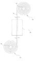
- such a composite is manufactured from a cylindrical body 3 formed by winding a long mat-like fiber material 1 around an axis of an axis 2 toward the axis 4.
- the tubular body 5 is vertically fixed so that the central axis of the tubular body 5 is along the vertical direction, and the sol solution impregnated in the tubular body 5 is gelled.
- the cylindrical body 5 is fixed in the vertical direction in the gelling step, and the sol solution impregnated in the cylindrical body 5 is vertical, that is, mat-like fiber material by gravity.
- 1 is a result of a difference in concentration between the sol solutions contained in the one end side and the other end of the cylindrical body 5 (for example, the concentration of the sol solution is the surface direction).
- the other end side portion is higher than the one end side portion.
- the weight and physical properties are higher on the other end side than on the one end side in the plane direction.
- Such a bias may occur in the thickness direction depending on the fixed state of the cylindrical body 5 in the gelling step, but in the surface direction in a mat-like base material in which the dimension in the thickness direction is relatively shorter than the dimension in the surface direction. Easy to manifest.
- the problem of this bias is not only when the cylindrical body 5 is fixed in the vertical direction in the gelling step, but also when the central axis of the cylindrical body 5 is fixed in the horizontal direction. is there. That is, when the cylindrical body 5 is fixed in the horizontal direction in the gelling step, it is included in one end side portion and the other end side portion in the radial direction along the vertical direction in the radial direction of the cylindrical body 5.
- the concentration difference in the sol solution for example, the result that the sol solution concentration is higher at the other end side than at the one end side in the radial direction
- the plane direction that is the longitudinal direction (length direction) The deviation (difference) in physical properties such as weight and thermal conductivity tends to be manifested between the one end side and the other end side.
- the problem of such a bias is not only a composite obtained from the cylindrical body 5 manufactured by winding the mat-like fiber material 1 around the central axis as described above, but also, for example, a rectangular shape (flat plate shape). The same applies to a composite obtained by using the mat-like fiber material 1 as it is.
- an object of the present invention is to provide a composite that can suppress the occurrence of weight and physical property bias, a manufacturing method thereof, and a cylindrical body including the composite.
- the influence of gravity is obtained by rotating a fibrous base material impregnated with a fluid sol solution, which is a raw material for producing xerogel, for a predetermined time in a state where the sol solution has fluidity. It was found that the sol solution can be uniformly dispersed in the fibrous base material, and the occurrence of uneven weight and physical properties can be suppressed in the composite.
- a fluid sol solution which is a raw material for producing xerogel
- the composite of the present invention is a composite having a xerogel and a fibrous base material supporting the xerogel, and the fibrous base material has a sheet shape, and a plurality of the fibrous base materials are arranged in a plane direction along the plane of the sheet shape.
- the xerogel is obtained by using the xerogel carrying amount per unit weight of each part cut out at a predetermined volume at each of the plurality of ends of the substrate. It is characterized by being uniformly dispersed and supported in the substrate so that the coefficient of variation of the xerogel loading obtained by dividing the standard deviation by the average value is 0.24 or less.
- the part can be configured to include a central part cut out at a predetermined volume in the center part in the surface direction of the base material.
- the base material has a normal direction of a sheet-shaped plane and has end portions facing each other in a thickness direction orthogonal to the surface direction, It is possible to include a thickness direction end portion cut out in a predetermined volume on each of the opposing both end sides in the thickness direction.
- the xerogel is obtained by using the bulk density of each part cut out at a predetermined volume at the center portion in the surface direction of the substrate and each of the plurality of end portions in the surface direction.
- the variation coefficient of the bulk density obtained by dividing the standard deviation of the bulk density by the average value can be dispersed and supported in the substrate so that it is 0.20 or less. .
- the base material impregnated with a fluid sol solution which is a raw material for producing the xerogel, is dried for a predetermined time under atmospheric pressure drying in a state where the sol solution is fluid. , And can be obtained by rotating.
- the cylindrical body of the present invention is a cylindrical body having a main body, and the main body has a sheet body having a xerogel and a fibrous base material carrying the xerogel wound around a central axis of the cylindrical body.
- the sheet is the composite.
- the method for producing a composite according to the present invention includes a xerogel and a fibrous base material supporting the xerogel, and the fibrous base material has a sheet shape and has a plurality of ends in a plane direction along the plane of the sheet shape.
- the xerogel is obtained by using the xerogel carrying amount per unit weight of each part cut out at a predetermined volume at each of the plurality of end portions of the base material, and the standard deviation of the xerogel carrying amount Is a method for producing a composite that is uniformly dispersed and supported in a base material such that the coefficient of variation of the xerogel support amount is 0.24 or less, It includes a gelling step of rotating the base material impregnated with a fluid sol solution for a predetermined time in a state where the sol solution is fluid.
- the predetermined time in the gelation step can be configured to be 1 hour or longer.
- the xerogel is obtained by using the xerogel carrying amount per unit weight of each part cut out at a predetermined volume at each of the plurality of ends in the surface direction of the base material. It is dispersed and supported in the substrate so that the coefficient of variation of the xerogel loading obtained by dividing the standard deviation by the average value is 0.24 or less. In other words, in such a composite, the xerogel is uniformly supported in the base material without being biased at the end in the surface direction of the base material, so that it is possible to suppress the occurrence of weight and physical property bias in the surface direction. .
- FIG. 1 is a schematic view showing a conventional method for producing a composite.
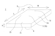
- FIG. 2 is a perspective view showing a composite according to an embodiment of the present invention.
- FIG. 3 is a schematic view showing a portion of the composite of one embodiment of the present invention cut out at a predetermined volume.
- FIG. 4 is a schematic view showing a portion of a composite body according to another embodiment of the present invention cut out at a predetermined volume.
- the composite according to the present embodiment includes a xerogel and a fibrous base material that supports the xerogel.
- a composite is, for example, a heat insulator having a heat insulating performance, and is used so as to be in close contact with the periphery of the pipe and to cover the heat.
- the base material of this embodiment is configured to have a sheet shape.
- the base material is configured so as to form a sheet shape (including a mat shape) in which one surface (front surface) and the other surface (back surface) opposite to the one surface are flat or substantially flat.
- the shape of the base sheet in plan view (top view) or bottom view (bottom view) is not particularly limited.
- the sheet shape can be configured as, for example, a polygon such as a triangle, a quadrangle, a pentagon, an L shape, a concave shape, and a convex shape, a round shape such as a circle and an ellipse, and a long shape in plan view.
- the quadrangle may be formed of, for example, a parallelogram, a trapezoid, a rectangle, or a square.
- the base material of the present embodiment has a plurality of end portions in the surface direction along the sheet-shaped plane, and is an end facing the normal direction of the sheet-shaped plane and in the thickness direction orthogonal to the surface direction. Configured to have a portion.
- the base material of the present embodiment includes a thickness direction, a length direction orthogonal to the thickness direction, and a width direction orthogonal to the thickness direction and intersecting (including orthogonal) the length direction.
- Each direction has a predetermined length
- the surface direction is composed of the length direction and the width direction.
- the base material of the present embodiment is configured to have opposite end portions in each direction of the sheet-shaped thickness direction and a surface direction orthogonal to the thickness direction.
- the base material of the present embodiment has a long rectangular sheet shape, and is configured to have a rectangular parallelepiped rectangular sheet shape as shown in FIG.
- seat shape of a base material is not specifically limited.
- the “thickness direction” is a normal direction (out-of-plane direction) of one surface (front surface) or the other surface (back surface) of the sheet shape (for example, direction H in FIG. 2).
- the above-mentioned “ends facing each other in the thickness direction” are one surface (sheet surface) side portion of the base material and the other surface (sheet back surface) opposite to the one surface and facing one surface in the thickness direction. It is a side portion (for example, the one surface side portion 7 and the other surface side portion 8 in FIG. 2).
- the “surface direction” is an in-plane direction along the sheet-shaped plane, and is a direction orthogonal to the thickness direction that is the normal direction of the sheet-shaped plane (for example, the direction S (L in FIG. 2). , W)).
- a surface direction is not particularly limited as long as it is a direction along a plane, and includes all directions extending in a planar shape.
- the edge part of a surface direction is a side part when a base material is planarly viewed (a side includes any case where the edge part is linear, arcuate, or curved) (for example, the edge of FIG. 2). Part 71-74).
- end facing each other in the plane direction are the one end side part of the base material in the sheet plane and the other end side part facing the one end side part in the plane direction ( For example, one end 71 and the other end 72 and / or one end 73 and the other end 74 of FIG. 2).
- the longitudinal direction of the rectangular shape is the length direction L
- the short direction which is the direction orthogonal to the length direction L
- the surface direction S is the length direction L and the width direction W.
- the thickness direction H is a direction orthogonal to the surface direction S (the length direction L and the width direction W).
- the pair of long side portions are end portions facing each other in the width direction W (surface direction S)
- the pair of short side portions one end portion 71 and the other end portion 72 are long. It is an edge part which opposes the direction L (surface direction S).
- Such a base material is composed of a fibrous material.
- One or both of organic and inorganic fibers can be used as the base fiber.
- inorganic fibers include inorganic fibers such as glass fiber and ceramic fiber, and organic fibers such as polyester and polyamide.
- the density (weight per unit area), thickness, and the like in the fibers of the base material are appropriately selected according to the object to which the composite material is attached.
- the xerogel of the present embodiment is a dry solid gel and a porous body having a porous structure.
- a xerogel is obtained, for example, by using an alkoxide compound as a gel raw material, mixing with a solvent, hydrolyzing, polycondensing and gelling, and then drying.
- the alkoxide compound is not particularly limited.
- a monofunctional to tetrafunctional alkoxide compound for example, DMDS (dimethyldimethoxysilane), MTMS (methyltrimethoxysilane), TMOS (tetramethoxysilane)
- the solvent is water and alcohol (for example, methanol, ethanol).
- the xerogel of the present invention is a solid gel obtained by drying an alkoxide compound.
- Such a xerogel is supported on a base material.
- the xerogel of the present embodiment has each part cut out at a predetermined volume at each of a plurality of end portions in the surface direction of the base material (specifically, each of the opposite end portions in the surface direction).
- the variation coefficient of the xerogel loading obtained by using the xerogel loading per unit weight is such that the variation coefficient of the xerogel loading obtained by dividing the standard deviation of the xerogel loading by the average value is 0.24 or less. It is uniformly dispersed in the substrate.
- the above “0.24” of the variation coefficient of the xerogel loading amount means 0.240 or less.
- the coefficient of variation of the xerogel loading is preferably 0.23 or less, 0.22 or less, 0.21 or less, 0.20 or less, 0.15 or less, 0.14 or less, 0.13 or less, 0.12 It is also possible to do the following.
- “uniform” means that the xerogel support is dispersed and supported in the substrate so that the variation coefficient of the xerogel support is 0.24 or less.
- the above-mentioned “parts” are a plurality of end portions (specifically, the surface direction S (L) in the surface direction S (each direction of the length direction L and the width direction W) of the base material carrying xerogel. , W) and at both ends 71-74 facing each other), at least the same number (for example, 1 to 10) or approximately the same number of portions cut out by a predetermined volume (same volume or substantially the same volume).
- the part of the present embodiment can be configured by only parts cut out at a predetermined volume on each end side 71-74 in the surface direction S of the base material (for example, among the parts 1a in FIG. 3). Specific sites 711, 721, 731, 741).
- the part may be constituted only by a part cut out at a predetermined volume on each end side 71-74, 7, 8 in each direction (surface direction S and thickness direction H) of the base material (for example, among the parts 11a in FIG. 4, specific parts 711, 721, 731, 741, 811, 841 and parts 721, 831 on the other surface 8 side adjacent to the parts 721, 731 in the thickness direction (not shown). ).
- the part may be composed of a part cut out at a predetermined volume on each end side 71-74 in the surface direction S of the base material and a central part cut out at a predetermined volume at the central part 75 of the base material.
- the part includes a part cut out at a predetermined volume on each end side 71-74, 7, 8 in each direction (surface direction S and thickness direction H) of the base material, and a predetermined volume at the central part 75 of the base material. It is also possible to comprise the central part cut out in (for example, specific parts 711, 721, 731, 741, 751, 811 and 841 in each part 11a of FIG. Sites 821, 831, 851 (not shown) on the other surface 8 side adjacent to each other in the thickness direction.
- the above-mentioned part can also be configured by small divided portions obtained by dividing the entire planar surface of the base material in a lattice shape (for example, a grid shape) in the thickness direction H (for example, all the parts in FIG. 3). Site 1a).
- the portion is obtained by further cutting each small divided portion into a predetermined volume at one end side (one surface side) 7 and the other end side (other surface side) 8 in the thickness direction H (for example, each small divided portion is thickened). It is also possible to include a thickness direction end portion (divided into two in the direction) (for example, all the portions 11a in FIG. 4).
- part cut off by predetermined volume are not specifically limited.
- the shape of the part may be, for example, a polygonal column shape (for example, a cubic shape) or a columnar shape such as the part 1a of FIG. 3 or the part 11a of FIG.
- the predetermined volume of sites for example, 6250mm 3 (25mm ⁇ 25mm ⁇ 10mm cube), 6250mm 3 (25mm ⁇ 25mm ⁇ 10mm cube), 3140mm 3 (10mm ⁇ 10mm ⁇ 3.14 ⁇ 10mm cylindrical body) Etc. are possible.
- the above “xerogel carrying amount” is the weight of the xerogel carried by the base material, in other words, the weight of the xerogel attached to the base material. Strictly speaking, the amount of xerogel supported is expressed as weight g2 (xerogel) using weight g1 of a predetermined volume of the substrate not supporting xerogel and weight g2 of the predetermined volume of the substrate supporting xerogel. The weight g1 (the weight of the portion of the predetermined volume in the base material not supporting xerogel) can be subtracted from the weight of the portion of the predetermined volume in the base material supporting.
- the amount of xerogel supported pays attention to the fact that the xerogel contains an organic group (organic group of the alkoxide compound), and thus the organic group is burnt down and the weight of the xerogel decreases when fired at a predetermined temperature or higher (for example, 500 ° C. or higher). From the weight g3 (total weight of the portion before firing) using the weight g3 of the portion having a predetermined volume and the weight g4 of the portion after firing obtained by firing the portion having the predetermined volume at a predetermined temperature. It is also possible to use a value obtained by subtracting g4 (total weight of the part after firing).
- xerogel support amount per unit weight of each part means the xerogel support using the weight in each part (part containing the base material and xerogel) of a predetermined volume and the xerogel support amount contained in the part. It is the value obtained by dividing the quantity by the weight.
- coefficient of variation of the xerogel loading is a value obtained by obtaining the standard deviation ⁇ and the average value m from the xerogel loading of each part and dividing the standard deviation ⁇ by the average value m.
- xerogel has a predetermined volume at the center portion in the surface direction of the base material and each of a plurality of end portions in the surface direction (specifically, the opposite end portions in the surface direction).
- the bulk density variation coefficient obtained by using the bulk density of each part cut out, and the bulk density variation coefficient obtained by dividing the standard deviation of the bulk density by the average value is uniform within the substrate so that it is 0.20 or less. Are dispersed and supported.
- the above-mentioned “parts” means a predetermined volume (in the surface direction center portion of the base material and a plurality of end portions in the surface direction (specifically, the opposite end portions in the surface direction), respectively.
- the same volume substantially the same volume
- the same number for example, 1 to 10
- This part is the same as the above part for obtaining the coefficient of variation of the xerogel loading (except for the structure consisting of only the end part in the surface direction of the substrate, and only the end part in the surface direction and the thickness direction). Can be configured.
- such a part can be constituted only by a part cut out at a predetermined volume at the center part in the surface direction of the substrate and each of a plurality of end parts in the surface direction (for example, among the parts 1a in FIG. 3).
- such a part can also be configured by subdivided parts obtained by dividing the entire planar surface of the base material in a lattice shape (for example, a grid pattern) in the thickness direction H (for example, all the parts in FIG. 3).
- Site 1a) Site 1a).
- the bulk density variation coefficient is preferably 0.200 or less, 0.19 or less, 0.18 or less, 0.17 or less, and the like.
- xerogel has a predetermined volume at the center portion in the surface direction of the base material and each of a plurality of end portions in the surface direction (specifically, the opposite end portions in the surface direction).
- the coefficient of variation of thermal conductivity obtained by using the thermal conductivity of each part cut out, and the coefficient of variation of thermal conductivity obtained by dividing the standard deviation of thermal conductivity by the average value is 0.06 or less. It is uniformly dispersed in the substrate.
- the above-mentioned “parts” means a predetermined volume (in the surface direction center portion of the base material and a plurality of end portions in the surface direction (specifically, the opposite end portions in the surface direction), respectively.
- the same volume substantially the same volume
- the same number for example, 1 to 10
- This part is the same as the above part for obtaining the coefficient of variation of the xerogel loading (except for the structure consisting of only the end part in the surface direction of the substrate, and only the end part in the surface direction and the thickness direction). Can be configured.
- such a part can be configured only by a part cut out at a predetermined volume at the center in the surface direction of the substrate and each of a plurality of end parts in the surface direction (for example, among the parts 1a in FIG. 3) Specific sites 711, 721, 731, 741, 751).
- such a part can also be configured by subdivided parts obtained by dividing the entire planar surface of the base material in a lattice shape (for example, a grid pattern) in the thickness direction H (for example, all the parts in FIG. 3). Site 1a).
- the cylindrical body of the present embodiment is a cylindrical body having a main body portion, and the main body portion includes a sheet body having a xerogel and a fibrous base material carrying the xerogel as a central axis of the cylindrical body.
- the sheet is wound around, and at least a part of the sheet is configured to be the composite.
- the configuration of the xerogel and the fibrous base material is the same as the configuration of the xerogel and the fibrous base material in the composite.
- the sheet body of the present embodiment has a long shape, and may be configured in a rectangular shape, for example.
- the sheet body of the present embodiment is composed of the composite, for example, the sheet body includes one or a plurality of the composites, or all the sheet bodies are one composite. It can also be configured.
- the sheet body includes one or a plurality of the composite bodies, the sheet body includes a connection body (not particularly limited, for example, a fibrous base material) connected to the composite body. It is also possible.
- seat body is comprised including the said some composite_body
- complex may be comprised by mutually connecting one edge part of a surface direction.
- a preparation step of preparing a sol solution obtained by mixing an alkoxide compound with a solvent (water and alcohol) to hydrolyze, an impregnation step of impregnating the substrate with the sol solution by, for example, coating or dipping, and a sol solution impregnated in the substrate It includes a gelling step of obtaining a wet gel by polycondensation to obtain a wet gel, and a drying step of drying the wet gel in the substrate (for example, atmospheric pressure drying or supercritical drying).
- the base material can be impregnated with a catalyst (for example, ammonia) together with the sol solution in order to promote polycondensation of the sol solution.
- the gelling step and the drying step can be the same step.
- the base material impregnated with a fluid sol solution that is a raw material for producing xerogel is made fluid, and the sol solution is made fluid by using a rotating device that can hold and rotate the base material.
- a rotation step of rotating for a predetermined time in the possessed state refers to a state before the sol solution is gelled, becomes viscous, and loses fluidity.
- the rotation time, rotation speed, and rotation axis direction are not particularly limited.
- the rotation time is within 30 minutes, preferably 30 minutes or more, more preferably 1 hour or more, and further preferably 1 hour and a half or more. More preferably, it is 2 hours or more.
- the rotation speed is 5 rpm (rotation per minute), preferably 15 rpm, more preferably 20 rpm, and even more preferably 10 rpm.
- the rotational axis direction includes only one axial direction, two axial directions of the first axial direction and the second axial direction intersecting (for example, orthogonal to) the first axial direction, and intersecting the two axial directions (for example, It is possible to configure in any of the three axial directions including the third axis direction (perpendicular).
- the rotation axis direction is constituted by only one axial direction, for example, either the vertical direction (gravity direction) or the horizontal direction may be used, but preferably the horizontal direction intersects with the gravity direction (for example, orthogonal).
- the rotation can be performed continuously or intermittently.
- the rotation and the stop can be alternately performed periodically or irregularly.
- one operation of stopping for 5 minutes after 5 minutes of rotation at 5 rpm can be performed three times (that is, a total of 30 minutes).
- the sol solution is in a fluid state, and before the sol solution is gelled and becomes viscous and loses fluidity, that is, at least the sol solution is gelled (highly viscous and fluidized.
- the influence of gravity is suppressed and the sol solution is uniformly dispersed in the substrate, so that the sol solution has a bias (concentration difference). Adhere so that it does not occur.
- the influence of gravity is suppressed, and the sol solution in the substrate is moved to the one end side in each direction (surface direction and thickness direction) of the substrate along the direction of gravity. Suppresses bias.
- the cylindrical body includes an impregnation step of impregnating the sheet body with the sol solution by, for example, coating or dipping, and a gelling step of obtaining a wet gel by polycondensing the sol solution impregnated into the sheet body to form a gel.
- a drying step of drying the wet gel in the sheet body for example, atmospheric pressure drying or supercritical drying
- a winding step of winding the sheet body around the central axis are included.
- the gelation step includes a rotation step similar to the gelation step in the composite, and in the rotation step, for example, around the center axis (specifically, around the center axis along the horizontal direction orthogonal to the gravity direction).
- the sheet body (or the cylindrical body formed by winding the sheet body) can be rotated.
- the gelling step and the drying step can be the same step.
- the winding step may be performed simultaneously with the impregnation step, or may be performed simultaneously with the gelling step and the drying step.
- the composite has a xerogel and a fibrous base material that supports the xerogel, and the fibrous base material has a sheet shape, and the planar surface of the sheet shape.
- the xerogel was cut out in a predetermined volume at each of the plurality of ends in the surface direction of the substrate (for example, opposite ends in the surface direction).
- the variation coefficient of the xerogel loading obtained by dividing the standard deviation of the xerogel loading by the average value obtained by using the xerogel loading per unit weight of each part is uniformly within the substrate. It is characterized by being supported in a dispersed manner.
- the xerogel has a standard deviation of the xerogel loading obtained by using the xerogel loading per unit weight of each part cut at a predetermined volume at each of the plurality of end portions in the surface direction of the substrate. It is uniformly dispersed and supported in the substrate so that the coefficient of variation of the xerogel loading divided by the average value is 0.24 or less.
- the xerogel is uniformly supported in the base material without unevenness at each end in the surface direction of the composite (for example, both ends facing each other in the surface direction). The occurrence of unevenness (difference) in weight and physical properties can be suppressed.
- the part includes a central part cut out at a predetermined volume in the central part in the surface direction of the base material.
- xerogel is uniformly supported in the base material without unevenness at each end and center in the surface direction of the composite, so that it is possible to suppress the occurrence of uneven weight and physical properties in the surface direction.
- the base material has end portions that are opposed to each other in a thickness direction orthogonal to the surface direction, which is a normal direction of a sheet-shaped plane, It includes a thickness direction end portion cut out at a predetermined volume on each of the opposing both end sides in the thickness direction of the material.
- the xerogel is obtained by using the xerogel loading amount per unit weight of each part cut at a predetermined volume at each of the surface direction and thickness direction ends of the substrate, and the standard deviation of the xerogel loading amount. Is distributed uniformly in the substrate so that the coefficient of variation of the xerogel loading is 0.24 or less.
- the xerogel is uniformly distributed in the base material without being biased at each end in the surface direction and the thickness direction of the composite (for example, both end sides facing each other in each direction of the surface direction and the thickness direction). Since it is carried, it is possible to suppress the occurrence of uneven weight and physical properties in the surface direction and thickness direction.
- the xerogel was cut out at a predetermined volume at the center portion in the surface direction of the substrate and each of a plurality of end portions in the surface direction (for example, opposite ends in the surface direction).
- the bulk density variation coefficient obtained by using the bulk density of each part, and the bulk density variation coefficient obtained by dividing the standard deviation of the bulk density by the average value is uniformly within the substrate so that it is 0.20 or less. It is dispersed and supported.
- xerogel uses the bulk density of each part cut out at a predetermined volume at the center in the surface direction of the substrate and each of a plurality of end portions in the surface direction (for example, opposite ends in the surface direction).
- the coefficient of variation of the bulk density obtained in this way, and the coefficient of variation obtained by dividing the standard deviation of the bulk density by the average value, is uniformly dispersed and supported in the substrate so that it is 0.20 or less.
- the bulk density is uniform in the base material without any deviation in the central portion of the base surface and the plurality of end portions in the surface direction, that is, in the surface direction. The occurrence of uneven weight and physical properties can be extremely suppressed.
- the cylindrical body according to the present embodiment is a cylindrical body having a main body portion, and the main body portion is a sheet body having a xerogel and a fibrous base material carrying the xerogel is the center of the cylindrical body.
- the sheet is wound around an axis, and at least a part of the sheet is the composite.
- the xerogel of the composite contained in the sheet body is a unit of each part cut out at a predetermined volume at each of a plurality of end portions in the surface direction of the substrate (for example, opposite ends in the surface direction). Obtained by using the amount of xerogel supported per weight, uniformly dispersed in the substrate so that the variation coefficient of the xerogel supported amount obtained by dividing the standard deviation of the xerogel supported amount by the average value is 0.24 or less. Has been.
- the xerogel contained in the composite is uniformly supported in the base material without unevenness at each end in the surface direction of the composite, and thus the weight and physical properties in the surface direction are uneven. Can be suppressed.
- the method for producing a composite according to the present embodiment includes a xerogel and a fibrous base material that supports the xerogel, and the fibrous base material has a sheet shape, and a plane direction along a plane of the sheet shape.
- the xerogel is obtained by using the xerogel loading per unit weight of each part cut out at a predetermined volume at each of the plurality of ends in the surface direction of the substrate.
- a method for producing a composite that is uniformly dispersed and supported in a base material such that the variation coefficient of the xerogel support divided by the average value of the standard deviation of the xerogel support is 0.24 or less It includes a gelling step of rotating the base material impregnated with a fluid sol solution, which is a raw material for producing the xerogel, for a predetermined time in a state where the sol solution is fluid.
- the rotation of the gelation step suppresses the influence of the fluid sol solution being biased in the substrate due to gravity, and the sol solution is uniformly dispersed and supported in the substrate. Therefore, it is possible to suppress the occurrence of weight and physical property bias in the composite.
- the predetermined time in the said gelatinization step is comprised so that it may be 1 hour or more.
- the fluid sol solution loses the fluidity and sufficiently influences the bias in the substrate due to the gravity of the sol solution before gelation. Therefore, the sol solution can be uniformly dispersed and supported in the base material, and the occurrence of uneven weight and physical properties in the composite can be reliably suppressed.
- the thermal conductivity of the composite of the present invention is not particularly limited.
- the thermal conductivity at 25 ° C. is 0.032 W / m ⁇ K or less, preferably 0.028 W / m ⁇ K or less, more preferably 0.020 W. / M ⁇ K or less.
- the thermal conductivity may be adjusted as appropriate by adjusting the density of the fibrous base material and the amount of xerogel.
- ⁇ Evaluation method> (Coefficient of variation of xerogel loading in the surface direction) 7 ⁇ 3 rectangular lattice tools (7mm ⁇ 25mm ⁇ 25mm ⁇ thickness 10mm for each grid) are arranged in the vertical direction (longitudinal direction) and three in the lateral direction (short direction).
- the rectangular sheet-shaped composite (length 100 mm ⁇ width 200 mm ⁇ thickness 10 mm) was penetrated in the thickness direction and divided into 32 parts (each part was a rectangular parallelepiped of length 25 mm ⁇ width 25 mm ⁇ thickness 10 mm).
- the weight G1 of each of these 32 parts and the weight G2 of each part after baking at 500 ° C. for about 2 hours were measured with a weigh scale.
- the amount of xerogel supported at each site was a value obtained by subtracting the weight G2 after firing from the weight G1 before firing.
- the amount of xerogel supported per unit weight at each site was calculated by (G1-G2) / G1.
- the standard deviation ⁇ and the average value m of the xerogel loading amount were calculated from the xerogel loading amount per unit weight of each part, and the variation coefficient of the xerogel loading amount was calculated by the standard deviation ⁇ / average value m.
- the 32 sites were divided into two on the one surface (one end) side and the other surface (the other end) side in the thickness direction to obtain 64 sites (a rectangular parallelepiped of 25 mm length ⁇ 25 mm width ⁇ 5 mm thickness).
- the weight G1 of each of these 64 parts and the weight G2 of each part after baking at 500 degreeC for about 2 hours were measured with the weigh scale.
- the amount of xerogel supported at each site was a value obtained by subtracting the weight G2 after firing from the weight G1 before firing.
- the amount of xerogel supported per unit weight at each site was calculated by (G1-G2) / G1.
- the standard deviation ⁇ and the average value m of the xerogel loading amount were calculated from the xerogel loading amount per unit weight of each part, and the variation coefficient of the xerogel loading amount was calculated by the standard deviation ⁇ / average value m.
- the bulk density of each of the 32 parts was measured, the standard deviation ⁇ of the bulk density and the average value m were calculated from the bulk density of each part, and the bulk density variation coefficient was calculated by the standard deviation ⁇ / average value m. .
- the volume of the bulk density measured the dimension of the vertical, horizontal, and thickness of each site
- the composite was wound around the outer peripheral surface of the pipe (diameter 65 mm), and it was observed whether a gap of 3 mm or more in the radial direction was generated. ⁇ indicates no gap, and ⁇ indicates one or more gaps.
- Example 1 A solvent composed of water and methanol and MTMS (methyltrimethoxysilane) were hydrolyzed while mixing at room temperature for 24 hours to prepare 600 g of a sol solution.
- the molar ratio of MTMS (methyltrimethoxysilane), water, and methanol is 1: 4: 4.
- 50 g of 5 wt% ammonia water (relative to the alkoxide) is added as a catalyst, and after impregnating the inorganic fiber base material (length 100 mm ⁇ width 200 mm ⁇ thickness 10 mm) made of glass fiber into the sol solution, the sol solution is contained.
- the base material is attached and fixed to the outer peripheral surface of a rotating body (specifically, a rotating body configured to be rotatable around a horizontal axis orthogonal to the vertical direction) in the rotating device, and the rotating shaft is rotated at 10 rpm for 120 minutes.
- a rotating body specifically, a rotating body configured to be rotatable around a horizontal axis orthogonal to the vertical direction
- the rotating shaft is rotated at 10 rpm for 120 minutes.
- the sol was dehydrated and condensed (polycondensation) to promote gelation.
- it was sealed using an incubator so that the solvent in the substrate would not volatilize, and kept at 70 ° C. to promote dehydration condensation (polycondensation), and the sol in the substrate was turned into a wet gel.
- the solvent in the base material was removed by drying the wet gel in the base material at 150 ° C. using an oven to obtain a composite.
- the obtained composite was evaluated by the above evaluation method.
- Example 2 In Example 2, composites were produced under the same conditions as Example 1, except that the molar ratio of MTMS, water and methanol was 1: 4: 5 in the sol solution. The obtained composite was evaluated by the above evaluation method.
- Example 3 In Example 3, composites were produced under the same conditions as Example 1, except that the molar ratio of MTMS, water and methanol was 1: 4: 6 in the sol solution. The obtained composite was evaluated by the above evaluation method.
- Example 4 In Example 4, composites were produced under the same conditions as Example 1, except that the molar ratio of MTMS, water and methanol was 1: 4: 7 in the sol solution. The obtained composite was evaluated by the above evaluation method.
- Example 5 In Example 5, composites were produced under the same conditions as Example 1, except that the molar ratio of MTMS, water, and methanol in the sol solution was 1: 4: 8. The obtained composite was evaluated by the above evaluation method.
- Example 6 In Example 6, the composite was produced under the same conditions except that Example 2 was different in that the rotational speed was 5 rpm. The obtained composite was evaluated by the above evaluation method.
- Example 7 In Example 7, a composite was produced under the same conditions except that Example 2 was different in that the rotational speed was 20 rpm. The obtained composite was evaluated by the above evaluation method.
- Example 8 In Example 8, composites were produced under the same conditions except that Example 2 was different in that the rotation time was 60 minutes. The obtained composite was evaluated by the above evaluation method.
- Example 9 In Example 9, the composite was produced under the same conditions except that Example 2 was different in that the rotation time was 90 minutes. The obtained composite was evaluated by the above evaluation method.
- Example 10 is the same as Example 2 except that the molar ratio of MTMS, DMDS (dimethyldimethoxysilane), water, and methanol is 0.98: 0.02: 4: 5 in the sol solution. A composite was produced under the conditions. The obtained composite was evaluated by the above evaluation method.
- Example 11 is the same as Example 2 except that the molar ratio of MTMS, TMOS (tetramethoxysilane), water, and methanol in the sol solution is 0.98: 0.02: 4: 5. A composite was produced under the conditions. The obtained composite was evaluated by the above evaluation method.
- Comparative Example 1 In Comparative Example 1, the length direction (longitudinal direction) which is the surface direction of the base material is the direction of gravity (vertical) when the base material is not rotated after being immersed in the sol solution (that is, the rotational time is 0 and the rotational speed is 0).
- the composites were manufactured under the same conditions, except that they were left standing in the vertical or vertical direction. The obtained composite was evaluated by the above evaluation method.
- Example 2 is a state in which the length direction (longitudinal direction) which is the surface direction of the substrate does not rotate after being immersed in the sol solution so that the length direction (longitudinal direction) is along the gravity direction (vertical direction).
- the composites were produced under the same conditions, except that they were left alone. The obtained composite was evaluated by the above evaluation method.
- Comparative Example 3 In Comparative Example 3, the length direction (longitudinal direction) which is the surface direction of the base material is set so as to be along the gravity direction (vertical direction) without rotating the base material after being immersed in the sol solution. The composites were produced under the same conditions, except that they were left alone. The obtained composite was evaluated by the above evaluation method.
- Example 4 is a state in which the length direction (longitudinal direction) which is the surface direction of the base material is set to be along the gravity direction (vertical direction) without rotating the base material after being immersed in the sol solution.
- the composites were produced under the same conditions, except that they were left alone. The obtained composite was evaluated by the above evaluation method.
- Example 5 is a state in which the length direction (longitudinal direction) which is the surface direction of the base material is set so as to be along the gravity direction (vertical direction) without being rotated after being immersed in the sol solution.
- the composites were produced under the same conditions, except that they were left alone. The obtained composite was evaluated by the above evaluation method.
- the composite according to this example has a small coefficient of variation in the xerogel loading and a bulk density variation coefficient, and is excellent in quality with less bias in weight and physical properties.
- it has an unexpected effect of being excellent in flexibility (adhesion or adhesion). That is, in addition to the above-mentioned problems, the present invention also has a problem that when a conventional composite is attached to the outer peripheral surface of a pipe, a gap is generated between the pipe and the composite to some extent, and the heat insulation effect is locally reduced. It is excellent in flexibility and can suppress a gap between the pipe and the composite to prevent the heat insulation effect from being locally lowered.
- the variation in the coefficient of variation of the xerogel loading is small even when the ratio of water to methanol with respect to the alkoxide compound is different as compared with Comparative Examples 1 to 5.
- the present invention has not been able to achieve sufficient hydrolysis and polycondensation if the ratio of water to alcohol is not properly blended with the alkoxide compound.
- the influence of the ratio of water and methanol on the alkoxide compound can be suppressed, and stable heat insulation performance can be achieved.
- complex is not limited to the said embodiment and an Example, A various change is possible in the range which does not deviate from the summary of this invention. .
- seat shape is planar view round shape (circle, In the case of an elliptical shape, the surface direction is a radial direction along each angle from the center of the circle (0 to 360 degrees, for example, 15 degree intervals, 30 degree intervals, 45 degree intervals, 90 degree intervals). be able to.
- the end in the surface direction is an arc portion in each radial direction at intervals of 30 degrees from the center of the circle (for example, a fan-shaped portion with a center angle of 30 degrees). Peripheral edge).
- each of the steps of the cylindrical body according to the above embodiment and a cutting step for cutting a part of the sheet body of the cylindrical body can be configured. is there.
- the cutting step can be configured to cut, for example, a position spaced a predetermined length in the longitudinal direction from the longitudinal end of the sheet member in the short direction.
- the application of the composite or cylindrical body of the present invention is not particularly limited, but can be used as, for example, a heat insulating material, a sealing material, a sound absorbing material, and the like.
Landscapes
- Engineering & Computer Science (AREA)
- Textile Engineering (AREA)
- Silicon Compounds (AREA)
Abstract
重量や物性の偏りが生じることを抑制できる複合体、その製造方法及び複合体を含む筒状体を提供することを課題とする。 本発明の複合体1は、キセロゲルと該キセロゲルを担持する繊維質基材とを有する複合体であって、前記繊維質基材は、シート形状をなし、該シート形状の平面に沿う面方向Sに複数の端部71,72,73,74を有しており、前記キセロゲルは、基材の前記複数の端部71,72,73,74の各々において所定体積で切り取られた各部位の単位重量当りのキセロゲル担持量を用いて得られる、キセロゲル担持量の標準偏差を平均値で除したキセロゲル担持量の変動係数が0.24以下であるように基材内に分散して担持されている。
Description
本発明は、キセロゲルと該キセロゲルを担持する繊維質基材とを有する複合体、その製造方法及び複合体を含む筒状体に関する。
従来、この種の複合体としては、エアロゲルと該エアロゲルを担持するマット状繊維材とを有するものが知られている(例えば特許文献1)。このような複合体は、例えばマット状繊維材の平面を湾曲させて配管周りに密着させて断熱被覆するように用いられる。
かかる複合体の製造は、例えば図1に示すように長尺なマット状繊維材1を軸芯2の軸周りに巻いてなる筒状体3からマット状繊維材1を軸芯4に向けて引き出しながら軸芯4の軸周りに筒状体5として巻き取る巻取ステップと、該巻取ステップ中において含浸装置6を用いてエアロゲルの製造原料であるゾル溶液をマット状繊維材1に含浸させる含浸ステップと、前記巻取ステップ後に筒状体5の中心軸が鉛直方向に沿うように筒状体5を垂直に立てて固定した状態にして、筒状体5に含浸したゾル溶液をゲル化(湿潤ゲルを作成)するゲル化ステップと、筒状体5の湿潤ゲルを乾燥する乾燥ステップと、筒状体5のマット状繊維材1を長手方向端部から長手方向に所定長離間した位置を短手方向に裁断することで複合体を得る裁断ステップとを有する。
しかしながら、上記従来の複合体では、ゲル化ステップにおいて筒状体5を鉛直方向に立てて固定した状態にしており、筒状体5に含浸したゾル溶液は重力によって鉛直方向、即ちマット状繊維材1の短手方向である面方向に沿って移動し、筒状体5の面方向一端側部と他端側部とに含まれるゾル溶液に濃度差が生じる結果(例えばゾル溶液濃度が面方向一端側部より他端側部のほうが高くなる結果)、得られた複合体では、面方向一端側部と他端側部とで重量や熱伝導率などの物性の偏り(差)が生じてしまう(例えば重量や物性が面方向一端側部より他端側部のほうが高くなる)。かかる偏りは、ゲル化ステップにおける筒状体5の固定状態によっては、厚み方向にも生じ得るが、厚み方向の寸法が面方向の寸法より相対的に極めて短いマット状の基材では面方向において顕在化し易い。
また、かかる偏りの問題は、前記ゲル化ステップにおいて筒状体5を鉛直方向に立てて固定した場合だけでなく、筒状体5の中心軸を水平方向に寝かして固定した場合においても同様である。即ち、ゲル化ステップで筒状体5を水平方向に寝かして固定した場合には、筒状体5の径方向のうち鉛直方向に沿う径方向の一端側部と他端側部とに含まれるゾル溶液に濃度差が生じる結果(例えばゾル溶液濃度が径方向一端側部より他端側部のほうが高くなる結果)、得られた複合体では、とりわけ長手方向(長さ方向)である面方向の一端部側と他端部側とで重量や熱伝導率などの物性の偏り(差)が顕在化し易い。さらに、このような偏りの問題は、上記のようにマット状繊維材1を中心軸周りに巻き取って製造される筒状体5から得られる複合体だけでなく、例えば矩形状(平板状)のマット状繊維材1をその形状のまま用いて得られる複合体の場合にも同様である。
そこで、本発明では、重量や物性の偏りが生じることを抑制できる複合体、その製造方法及び複合体を含む筒状体を提供することを課題とする。
本発明では、キセロゲルの製造原料であり流動性を有するゾル溶液が含浸した繊維質基材を、前記ゾル溶液が流動性を有している状態において所定時間、回転させることにより、重力の影響を抑制して、ゾル溶液を繊維質基材内に一様に分散させることができ、複合体において重量や物性の偏りが生じることを抑制できることを見出した。
本発明の複合体は、キセロゲルと該キセロゲルを担持する繊維質基材とを有する複合体であって、前記繊維質基材は、シート形状をなし、該シート形状の平面に沿う面方向に複数の端部を有しており、前記キセロゲルは、基材の前記複数の端部の各々において所定体積で切り取られた各部位の単位重量当りのキセロゲル担持量を用いて得られる、キセロゲル担持量の標準偏差を平均値で除したキセロゲル担持量の変動係数が0.24以下であるように基材内に一様に分散して担持されていることを特徴とする。
また、本発明の複合体では、前記部位は、基材の面方向中央部において所定体積で切り取られた中央部位を含むように構成することが可能である。
また、本発明の複合体では、前記基材は、シート形状の平面の法線方向であり前記面方向に直交する厚み方向において対向する端部を有しており、前記部位は、基材の厚み方向の前記対向する両端部側の各々において所定体積で切り取られた厚み方向端部位を含むように構成することが可能である。
また、本発明の複合体では、前記キセロゲルは、基材の面方向中央部と面方向の前記複数の各端部とにおいて所定体積で切り取られた各部位の嵩密度を用いて得られる嵩密度の変動係数であって嵩密度の標準偏差を平均値で除した嵩密度の変動係数が0.20以下であるように基材内に分散して担持されるように構成することが可能である。
また、本発明の複合体では、前記キセロゲルの製造原料であり流動性を有するゾル溶液が含浸した前記基材を、前記ゾル溶液が流動性を有している状態において常圧乾燥下で所定時間、回転させて得られるように構成することが可能である。
本発明の筒状体は、本体部を有する筒状体であって、前記本体部は、キセロゲルと該キセロゲルを担持する繊維質基材とを有するシート体が筒状体の中心軸周りに巻かれてなり、該シート体の少なくとも一部が前記複合体であることを特徴とする。
本発明の複合体の製造方法は、キセロゲルと該キセロゲルを担持する繊維質基材とを備え、前記繊維質基材は、シート形状をなし、該シート形状の平面に沿う面方向に複数の端部を有しており、前記キセロゲルは、基材の前記複数の端部の各々において所定体積で切り取られた各部位の単位重量当りのキセロゲル担持量を用いて得られる、キセロゲル担持量の標準偏差を平均値で除したキセロゲル担持量の変動係数が0.24以下であるように基材内に一様に分散して担持されている複合体の製造方法であって、前記キセロゲルの製造原料であり流動性を有するゾル溶液が含浸した前記基材を、前記ゾル溶液が流動性を有している状態において所定時間、回転させるゲル化ステップを含むことを特徴とする。
また、本発明の複合体の製造方法では、前記ゲル化ステップにおける所定時間は、1時間以上であるように構成すること可能である。
本発明に係る複合体では、キセロゲルは、基材の面方向の複数の端部の各々において所定体積で切り取られた各部位の単位重量当りのキセロゲル担持量を用いて得られる、キセロゲル担持量の標準偏差を平均値で除したキセロゲル担持量の変動係数が0.24以下であるように基材内に分散して担持されている。換言すれば、かかる複合体では、キセロゲルは基材の面方向の端部側で偏りなく基材内に一様に担持されているので、面方向における重量や物性の偏りが生じることを抑制できる。
本発明の複合体、該複合体を含む筒状体の実施形態について図面を参照しつつ説明する。本実施形態の複合体は、キセロゲルと該キセロゲルを担持する繊維質基材とを有して構成される。かかる複合体は、例えば断熱性能を有する断熱体であり、配管周りに密着させて断熱被覆するように用いられる。
本実施形態の基材は、シート形状をなすように構成される。具体的には、基材は、一面(表面)と該一面の反対面である他面(裏面)とが平面又は略平面をなすシート形状(マット形状を含む)をなすように構成される。基材のシート形状を平面視(上面視)又は底面視(下面視)した形状は、特に限定されない。シート形状は、平面視において例えば三角形、四角形、五角形、L字形、凹字形、凸字形などの多角形や、円形、楕円形などの丸形、長尺な形状として構成され得る。また、前記四角形は、例えば平行四辺形、台形、長方形、正方形などで構成され得る。
また、本実施形態の基材は、前記シート形状の平面に沿う面方向において複数の端部を有すると共に、シート形状の平面の法線方向であり前記面方向に直交する厚み方向において対向する端部を有するように構成される。具体的には、本実施形態の基材は、厚み方向と、該厚み方向に直交する長さ方向と、前記厚み方向に直交して長さ方向に交差(直交を含む)する幅方向との各方向に所定長を有してなり、面方向が前記長さ方向と幅方向とで構成される。より具体的には、本実施形態の基材は、前記シート形状の厚み方向と該厚み方向に直交する面方向との各方向において対向する端部を有するように構成される。さらに具体的には、本実施形態の基材は、長尺な矩形シート状であり、図2に示すように直方体の矩形シート状であるように構成される。なお、基材のシート形状の寸法は特に限定されない。
ここで、上記の「厚み方向」とは、シート形状の一面(表面)又は他面(裏面)の法線方向(面外方向)である(例えば図2の方向H)。また、上記の「厚み方向において対向する端部」とは、基材の一面(シート表面)側部分と該一面の反対面であって一面に対して厚み方向に対向する他面(シート裏面)側部分のことである(例えば図2の一面側部分7,他面側部分8)。
また、上記の「面方向」とは、シート形状の平面に沿う面内方向であり、シート形状の平面の法線方向である厚み方向に直交する方向である(例えば図2の方向S(L,W))。かかる面方向は、平面に沿う方向であれば特に限定せず、面状に拡がっていく方向全般を含む。また、面方向の端部とは、基材を平面視したときの辺部(辺は端縁部が直線状、円弧状、曲線状のいずれの場合も含む)である(例えば図2の端部71-74)。また、上記の「面方向において対向する端部」とは、シート平面における基材の一端部側部分と該一端部側部分に対して面方向に対向する他端部側部分のことである(例えば図2の一端部71と他端部72、及び/又は、一端部73と他端部74)。
本実施形態の基材では、図2に示すように矩形状(又は長尺形状)の長手方向が長さ方向Lであり、該長さ方向Lに直交する方向である短手方向が幅方向Wである。かかる基材では、面方向Sは長さ方向Lと幅方向Wである。また、厚さ方向Hは、面方向S(長さ方向Lと幅方向W)に直交する方向である。一対の長辺部(一端部73と他端部74)は幅方向W(面方向S)に対向する端部であり、一対の短辺部(一端部71と他端部72)は長さ方向L(面方向S)に対向する端部である。
かかる基材は、繊維質で構成される。基材の繊維は、有機及び無機繊維のいずれか一方又は両方を用いることができる。但し、耐熱性の観点からは、基材の繊維は無機繊維を用いるほうが好ましい。基材の繊維としては、具体的には、ガラスファイバー、セラミックファイバー等の無機繊維や、ポリエステルやポリアミド等の有機繊維が挙げられる。また、基材の繊維における密度(目付け量)や厚さ等は、複合材が取り付けられる被対象物に応じて適宜選択される。
本実施形態のキセロゲルは、乾燥した固形状のゲルであり、多孔質構造を有する多孔体である。かかるキセロゲルは、例えばアルコキシド化合物をゲル原料とし、溶媒に混合して加水分解し、重縮合してゲル化させた後に乾燥して得られる。アルコキシド化合物は特に限定されないが、例えば1乃至4官能のアルコキシド化合物(例えばDMDS(ジメチルジメトキシシラン)、MTMS(メチルトリメトキシシラン)、TMOS(テトラメトキシシラン))を採用することが可能である。溶媒は、水及びアルコール(例えばメタノール、エタノール)である。
なお、本発明のキセロゲルは、アルコキシド化合物を乾燥して得られる固体状のゲルのことであり、アルコキシド化合物を常圧乾燥法によって製造して得られる乾燥ゲル、アルコキシド化合物を凍結乾燥法によって製造して得られるクリオゲル、アルコキシド化合物を超臨界乾燥法によって製造して得られるエアロゲルを含むものである。
かかるキセロゲルは、基材に担持されている。具体的には、本実施形態のキセロゲルは、基材の面方向の複数の各端部(具体的には、面方向の前記対向する両端部側の各々)において所定体積で切り取られた各部位の単位重量当りのキセロゲル担持量を用いて得られるキセロゲル担持量の変動係数であって、キセロゲル担持量の標準偏差を平均値で除したキセロゲル担持量の変動係数が0.24以下であるように基材内に一様に分散して担持されている。キセロゲル担持量の変動係数の上記「0.24」は、0.240以下を意味する。その他、キセロゲル担持量の変動係数は、好ましくは0.23以下、0.22以下、0.21以下、0.20以下、0.15以下、0.14以下、0.13以下、0.12以下などとすることも可能である。なお、本発明において、「一様」とは、キセロゲル担持量の変動係数が0.24以下であるように基材内に分散して担持されていることを意味する。
ここで、上記の「部位」は、キセロゲルを担持した基材の面方向S(長さ方向L及び幅方向Wの各方向)の複数の各端部(具体的には、面方向S(L,W)で対向する両端部71-74の各々)において所定体積(同体積又は略同体積)で同数(例えば1乃至10)又は略同数分だけ切り取られた部位を少なくとも含んで構成される。本実施形態の部位は、例えば、基材の面方向Sの各端部側71-74において所定体積で切り取った部位のみで構成されることが可能である(例えば図3の各部位1aのうち特定の部位711,721,731,741)。その他、前記部位は、基材の各方向(面方向S及び厚み方向H)の各端部側71-74,7,8において所定体積で切り取った部位のみで構成されることも可能である(例えば図4の各部位11aのうち特定の部位711,721,731,741,811,841と前記部位721,731に厚み方向に各々隣接する他面8側の部位821,831(図示せず))。その他、前記部位は、基材の面方向Sの各端部側71-74において所定体積で切り取った部位と、基材の中央部75において所定体積で切り取った中央部位とで構成されることも可能である(例えば図3の各部位1aのうち特定の部位711,721,731,741,751)。その他、前記部位は、基材の各方向(面方向S及び厚み方向H)の各端部側71-74,7,8において所定体積で切り取った部位と、基材の中央部75において所定体積で切り取った中央部位とで構成されることも可能である(例えば図4の各部位11aのうち特定の部位711,721,731,741,751,811,841と前記部位721,731,751に厚み方向に各々隣接する他面8側の部位821,831,851(図示せず))。その他、前記部位は、基材の平面全域を格子状(例えば碁盤目状)に厚み方向Hに貫通させて分割した各小分割部分で構成されることも可能である(例えば図3の全ての部位1a)。その他、前記部位は、前記各小分割部分をさらに厚み方向Hの一端側(一面側)7と他端側(他面側)8とにおいて所定体積で切り取った(例えば前記各小分割部分を厚み方向に2分割した)厚み方向端部位を含んで構成されることも可能である(例えば図4の全ての部位11a)。
なお、所定体積で切り取られる部位の所定体積や形状は、特に限定されない。部位の形状は、例えば図3の部位1aや図4の部位11aのような多角柱状(例えば立方体状)、円柱状などが可能である。また、部位の所定体積は、例えば、6250mm3(25mm×25mm×10mmの立方体)、6250mm3(25mm×25mm×10mmの立方体)、3140mm3(10mm×10mm×3.14×10mmの円柱体)などが可能である。
上記の「キセロゲル担持量」とは、基材が担持するキセロゲルの重量であり、換言すれば、基材に付着するキセロゲルの重量である。かかるキセロゲル担持量は厳密には、キセロゲルを担持していない基材における所定体積の部位の重量g1と、キセロゲルを担持した基材における所定体積の部位の重量g2とを用いて、重量g2(キセロゲルを担持した基材における所定体積の部位の重量)から重量g1(キセロゲルを担持していない基材における所定体積の部位の重量)を引き算した値とすることができる。或いはキセロゲル担持量は、キセロゲルが有機基(アルコキシド化合物の有機基)を含むため所定温度以上(例えば500℃以上)で焼成すると前記有機基が焼失してキセロゲルの重量は減少する点に着目して、所定体積の部位の重量g3と、前記所定体積の部位を所定温度で焼成して得られる焼成後の前記部位の重量g4とを用いて、重量g3(焼成前の部位の総重量)から重量g4(焼成後の部位の総重量)を引き算した値とすることも可能である。
上記の「各部位の単位重量当りのキセロゲル担持量」とは、所定体積の各部位(基材とキセロゲルとを含む部位)における重量と該部位に含まれるキセロゲル担持量とを用いて、キセロゲル担持量を重量で除した値である。
上記の「キセロゲル担持量の変動係数」とは、各部位のキセロゲル担持量から標準偏差σと平均値mと求め、標準偏差σを平均値mで除算した値である。
また、本実施形態の複合体において、キセロゲルは、基材の面方向中央部と面方向の複数の各端部(具体的には、面方向の前記対向する両端部側)とにおいて所定体積で切り取られた各部位の嵩密度を用いて得られる嵩密度変動係数であって嵩密度の標準偏差を平均値で除した嵩密度変動係数が0.20以下であるように基材内に一様に分散して担持されている。
ここで、上記の「部位」とは、基材の面方向中央部と面方向の複数の各端部(具体的には、面方向の前記対向する両端部側)とにおいてそれぞれ、所定体積(同体積又は略同体積)で同数(例えば1乃至10)又は略同数切り取られた部位を少なくとも含んで構成される。かかる部位は、キセロゲル担持量の変動係数を求めるための前記部位(基材の面方向の各端部の部位のみ、面方向及び厚み方向の各端部の部位のみからなる構成を除く)と同様に構成することができる。例えば、かかる部位は、基材の面方向中央部と面方向の複数の各端部とにおいて所定体積で切り取られた部位のみで構成することが可能である(例えば図3の各部位1aのうち特定の部位711,721,731,741,751)。その他、かかる部位は、基材の平面全域を格子状(例えば碁盤目状)に厚み方向Hに貫通させて分割した各小分割部分で構成されることも可能である(例えば図3の全ての部位1a)。また、嵩密度変動係数は、好ましくは0.200以下、0.19以下、0.18以下、0.17以下などとすることも可能である。
また、本実施形態の複合体において、キセロゲルは、基材の面方向中央部と面方向の複数の各端部(具体的には、面方向の前記対向する両端部側)とにおいて所定体積で切り取られた各部位の熱伝導率を用いて得られる熱伝導率の変動係数であって熱伝導率の標準偏差を平均値で除した熱伝導率の変動係数が0.06以下であるように基材内に一様に分散して担持されている。
ここで、上記の「部位」とは、基材の面方向中央部と面方向の複数の各端部(具体的には、面方向の前記対向する両端部側)とにおいてそれぞれ、所定体積(同体積又は略同体積)で同数(例えば1乃至10)又は略同数切り取られた部位を少なくとも含んで構成される。かかる部位は、キセロゲル担持量の変動係数を求めるための前記部位(基材の面方向の各端部の部位のみ、面方向及び厚み方向の各端部の部位のみからなる構成を除く)と同様に構成することができる。例えば、かかる部位は、基材の面方向中央部と面方向の複数の各端部とにおいて所定体積で切り取られた部位のみで構成することも可能である(例えば図3の各部位1aのうち特定の部位711,721,731,741,751)。その他、かかる部位は、基材の平面全域を格子状(例えば碁盤目状)に厚み方向Hに貫通させて分割した各小分割部分で構成されることも可能である(例えば図3の全ての部位1a)。
また、本実施形態の筒状体は、本体部を有する筒状体であって、前記本体部は、キセロゲルと該キセロゲルを担持する繊維質基材とを有するシート体が筒状体の中心軸周りに巻かれてなり、該シート体の少なくとも一部が前記複合体であるように構成される。キセロゲル及び繊維質基材の構成は、上記複合体におけるキセロゲル及び繊維質基材の構成と同様である。本実施形態のシート体は、長尺な形状をなし、例えば矩形状で構成され得る。また、本実施形態のシート体は、少なくとも一部が前記複合体で構成されており、例えばシート体が一又は複数の前記複合体を含んで構成されたり、シート体全てが一の複合体で構成されることも可能である。例えば、シート体が一又は複数の前記複合体を含んで構成される場合、シート体は、前記複合体に連結される連結体(特に限定しないが、例えば繊維質基材)を含んで構成することも可能である。また、シート体が複数の前記複合体を含んで構成される場合、各複合体は面方向の一の端部同士を互いに連結して構成され得る。
以上の構成からなる本実施形態の複合体、筒状体の製造方法について説明する。アルコキシド化合物を溶媒(水及びアルコール)に混合して加水分解したゾル溶液を作成する作成ステップと、ゾル溶液を例えば塗布又は浸漬により基材に含浸させる含浸ステップと、基材に含浸したゾル溶液を重縮合してゲル化させて湿潤ゲルを得るゲル化ステップと、基材内の湿潤ゲルを乾燥(例えば常圧乾燥又は超臨界乾燥)する乾燥ステップとを含む。前記含浸ステップでは、ゾル溶液の重縮合を促進させるため触媒(例えばアンモニア)をゾル溶液と共に基材に含浸させることができる。なお、ゲル化ステップと乾燥ステップとは同一ステップとすることも可能である。
ここで、ゲル化ステップは、キセロゲルの製造原料であり流動性を有するゾル溶液が含浸した前記基材を、該基材を保持して回転可能な回転装置を用いて前記ゾル溶液が流動性を有している状態において所定時間、回転させる回転ステップを含む。「ゾル溶液が流動性を有している状態」とは、ゾル溶液がゲル化して粘性が高くなり流動性を失う前の状態である。本ゲル化ステップでは、回転時間及び回転速度及び回転軸方向は、特に限定されないが、例えば回転時間は30分以内、好ましくは30分以上、より好ましくは1時間以上、さらに好ましくは1時間半以上、さらに好ましくは2時間以上である。また、回転速度は、5rpm(rotation per minute、回転毎分)、好ましく15rpm、より好ましくは20rpm、さらに好ましくは10rpmである。また、回転軸方向は、一つの軸方向のみ、第一軸方向と該第一軸方向に交差(例えば直交)する第二軸方向との2つの軸方向、該2つの軸方向に交差(例えば直交)する第三軸方向を加えた3つの軸方向のいずれで構成することも可能である。回転軸方向が一つの軸方向のみで構成される場合には、例えば鉛直方向(重力方向)、水平方向のいずれでもよいが、好ましくは重力方向に交差(例えば直交)する水平方向である。また、回転は、連続的、又は、断続的に行うことができ、例えば回転が断続的な場合には、回転と停止とを交互に定期的又は変則的に繰り返し行うことができる。回転と停止とを交互に定期的に行う場合、例えば5rpmで5分間の回転の後に5分間の停止をするという一回の動作を3回(即ち合計30分間)実施することができる。
このようにゲル化ステップにおいて、ゾル溶液が流動性を有している状態であってゾル溶液がゲル化して粘性が高くなり流動性を失う前、即ち少なくともゾル溶液がゲル化(粘性が高く流動性が失われた湿潤ゲルを作成)する間に基材を回転させることによって、重力による影響を抑制して基材内にゾル溶液を一様に分散させてゾル溶液の偏り(濃度差)が生じないように付着させる。換言すれば、かかるゲル化ステップの回転によって、重力による影響を抑制して基材内にゾル溶液が重力方向に沿って基材の各方向(面方向及び厚み方向)の一の端部側に偏ることを抑制する。
また、筒状体は、前記ゾル溶液を例えば塗布又は浸漬によりシート体に含浸させる含浸ステップと、シート体に含浸したゾル溶液を重縮合してゲル化させて湿潤ゲルを得るゲル化ステップと、シート体内の湿潤ゲルを乾燥(例えば常圧乾燥又は超臨界乾燥)する乾燥ステップと、シート体を中心軸周りに巻き取る巻取ステップとを含む。ここで、ゲル化ステップは、前記複合体におけるゲル化ステップと同様に回転ステップを含み、回転ステップでは、例えば前記中心軸周り(具体的には、重力方向に直交する水平方向に沿う中心軸周り)にシート体(又はシート体が巻き取られてなる筒状体)を回転することができる。なお、ゲル化ステップと乾燥ステップとは同一ステップとすることも可能である。巻取ステップは、含浸ステップと同時に実施してもよいし、ゲル化ステップや乾燥ステップと同時に実施してもよい。
以上、本実施形態に係る複合体によれば、キセロゲルと該キセロゲルを担持する繊維質基材とを有する複合体であって、前記繊維質基材は、シート形状をなし、該シート形状の平面に沿う面方向に複数の端部を有しており、前記キセロゲルは、基材の面方向の前記複数の端部(例えば面方向の対向する両端部側)の各々において所定体積で切り取られた各部位の単位重量当りのキセロゲル担持量を用いて得られる、キセロゲル担持量の標準偏差を平均値で除したキセロゲル担持量の変動係数が0.24以下であるように基材内に一様に分散して担持されていることを特徴とする。
かかる複合体では、キセロゲルは、基材の面方向の複数の端部の各々において所定体積で切り取られた各部位の単位重量当りのキセロゲル担持量を用いて得られる、キセロゲル担持量の標準偏差を平均値で除したキセロゲル担持量の変動係数が0.24以下であるように基材内に一様に分散して担持されている。換言すれば、かかる複合体では、キセロゲルは複合体の面方向の各端部(例えば面方向において対向する両端部側)で偏りなく基材内に一様に担持されているので、面方向における重量や物性の偏り(差異)が生じることを抑制できる。
また、本実施形態に係る複合体では、前記部位は、基材の面方向中央部において所定体積で切り取られた中央部位を含む。
かかる複合体では、キセロゲルは複合体の面方向の各端部と中央部とで偏りなく基材内に一様に担持されているので、面方向における重量や物性の偏りが生じることを抑制できる。
また、本実施形態に係る複合体では、前記基材は、シート形状の平面の法線方向であり前記面方向に直交する厚み方向において対向する端部を有しており、前記部位は、基材の厚み方向の前記対向する両端部側の各々において所定体積で切り取られた厚み方向端部位を含む。
かかる複合体では、キセロゲルは、基材の面方向及び厚み方向の端部の各々において所定体積で切り取られた各部位の単位重量当りのキセロゲル担持量を用いて得られる、キセロゲル担持量の標準偏差を平均値で除したキセロゲル担持量の変動係数が0.24以下であるように基材内に一様に分散して担持されている。換言すれば、かかる複合体では、キセロゲルは複合体の面方向及び厚み方向の各端部(例えば面方向及び厚み方向の各方向において対向する両端部側)において偏りなく基材内に一様に担持されているので、面方向及び厚み方向における重量や物性の偏りが生じることを抑制できる。
また、本実施形態に係る複合体では、前記キセロゲルは、基材の面方向中央部と面方向の複数の各端部(例えば面方向の対向する両端部側)とにおいて所定体積で切り取られた各部位の嵩密度を用いて得られる嵩密度の変動係数であって嵩密度の標準偏差を平均値で除した嵩密度の変動係数が0.20以下であるように基材内に一様に分散して担持されている。
かかる複合体では、キセロゲルは、基材の面方向中央部と面方向の複数の各端部(例えば面方向の対向する両端部側)とにおいて所定体積で切り取られた各部位の嵩密度を用いて得られる嵩密度の変動係数であって嵩密度の標準偏差を平均値で除した変動係数が0.20以下であるように基材内に一様に分散して担持されている。換言すれば、かかる複合体では、嵩密度は基材の面方向中央部と面方向の複数の各端部、即ち面方向において偏りなく基材内で一様になっているので、面方向において重量や物性の偏りが生じることを極めて抑制できる。
また、本実施形態に係る筒状体は、本体部を有する筒状体であって、前記本体部は、キセロゲルと該キセロゲルを担持する繊維質基材とを有するシート体が筒状体の中心軸周りに巻かれてなり、該シート体の少なくとも一部が前記複合体であることを特徴とする。
かかる筒状体では、シート体に含まれる複合体のキセロゲルは、基材の面方向の複数の各端部(例えば面方向の対向する両端部側)において所定体積で切り取られた各部位の単位重量当りのキセロゲル担持量を用いて得られる、キセロゲル担持量の標準偏差を平均値で除したキセロゲル担持量の変動係数が0.24以下であるように基材内に一様に分散して担持されている。換言すれば、かかる筒状体では、複合体に含まれるキセロゲルは複合体の面方向の各端部において偏りなく基材内に一様に担持されているので、面方向における重量や物性の偏りが生じることを抑制できる。
また、本実施形態に係る複合体の製造方法は、キセロゲルと該キセロゲルを担持する繊維質基材とを備え、前記繊維質基材は、シート形状をなし、該シート形状の平面に沿う面方向に複数の端部を有しており、前記キセロゲルは、基材の面方向の前記複数の各端部において所定体積で切り取られた各部位の単位重量当りのキセロゲル担持量を用いて得られる、キセロゲル担持量の標準偏差を平均値で除したキセロゲル担持量の変動係数が0.24以下であるように基材内に一様に分散して担持されている複合体の製造方法であって、前記キセロゲルの製造原料であり流動性を有するゾル溶液が含浸した前記基材を、前記ゾル溶液が流動性を有している状態において所定時間、回転させるゲル化ステップを含むことを特徴とする。
かかる複合体の製造方法では、ゲル化ステップの回転によって、流動性のゾル溶液が重力によって基材内で偏る影響を抑制して、ゾル溶液が基材内に一様に分散させて担持されるため、複合体内において重量や物性の偏りが生じることを抑制できる。
また、本実施形態に係る複合体の製造方法では、前記ゲル化ステップにおける所定時間は、1時間以上であるように構成される。
かかる複合体の製造方法では、ゲル化ステップの回転時間が1時間以上であると、流動性のゾル溶液が流動性を失いゲル化する前にゾル溶液の重力によって基材内で偏る影響を十分に抑制して、ゾル溶液が基材内に一様に分散させて担持でき、複合体内において重量や物性の偏りが生じることを確実に抑制できる。
本発明の複合体の熱伝導率は特に限定はされないが、例えば25℃における熱伝導率が0.032W/m・K以下、好ましくは0.028W/m・K以下、より好ましくは0.020W/m・K以下となるように製造することができる。ここで熱伝導率が0.032W/m・Kより高いと十分な断熱効果が得られ難い。熱伝導率は、繊維質基材の密度とキセロゲル量を適宜調整すればよい。
以下、本発明の実施例1乃至11、比較例1乃至5について説明する。実施例・比較例から得られた複合体について以下の評価をした。実施例1乃至11の結果と比較例1乃至5の結果とを表1に示す。
<評価方法>
(面方向におけるキセロゲル担持量の変動係数)
縦方向(長手方向)に7つ、横方向(短手方向)に3つ並んでなる7×3の矩形状格子具(格子具の各枡目は、縦25mm×横25mm×厚み10mm)を用いて、矩形シート状の複合体(縦100mm×横200mm×厚み10mm)の厚み方向に貫通させて32個の部位(各部位は縦25mm×横25mm×厚み10mmの直方体)に分割した。これら32個の各部位の重量G1と、500℃で2時間程度焼成した後の各部位の重量G2とを重量計で計測した。各部位のキセロゲル担持量を焼成前の重量G1から焼成後の重量G2を引いた値とした。各部位の単位重量当りのキセロゲル担持量を(G1-G2)/G1により算出した。各部位の単位重量当りのキセロゲル担持量からキセロゲル担持量の標準偏差σと平均値mとを算出して、キセロゲル担持量の変動係数を標準偏差σ/平均値mにより算出した。
(面方向及び厚み方向におけるキセロゲル担持量の変動係数)
前記32個の部位を厚み方向の一面(一端)側と他面(他端)側とに2分割して64個の部位(縦25mm×横25mm×厚み5mmの直方体)を得た。これら64個の各部位の重量G1と、500℃で2時間程度焼成した後の各部位の重量G2とを重量計で計測した。各部位のキセロゲル担持量を焼成前の重量G1から焼成後の重量G2を引いた値とした。各部位の単位重量当りのキセロゲル担持量を(G1-G2)/G1により算出した。各部位の単位重量当りのキセロゲル担持量からキセロゲル担持量の標準偏差σと平均値mとを算出して、キセロゲル担持量の変動係数を標準偏差σ/平均値mにより算出した。
前記32個の部位を厚み方向の一面(一端)側と他面(他端)側とに2分割して64個の部位(縦25mm×横25mm×厚み5mmの直方体)を得た。これら64個の各部位の重量G1と、500℃で2時間程度焼成した後の各部位の重量G2とを重量計で計測した。各部位のキセロゲル担持量を焼成前の重量G1から焼成後の重量G2を引いた値とした。各部位の単位重量当りのキセロゲル担持量を(G1-G2)/G1により算出した。各部位の単位重量当りのキセロゲル担持量からキセロゲル担持量の標準偏差σと平均値mとを算出して、キセロゲル担持量の変動係数を標準偏差σ/平均値mにより算出した。
(嵩密度変動係数)
前記32個の各部位の嵩密度を計測し、各部位の嵩密度から嵩密度の標準偏差σと平均値mとを算出して、嵩密度変動係数を標準偏差σ/平均値mにより算出した。なお、嵩密度の体積は、寸法計測装置(例えばノギス)を用いて、各部位の縦、横、厚みの寸法を計測した。
前記32個の各部位の嵩密度を計測し、各部位の嵩密度から嵩密度の標準偏差σと平均値mとを算出して、嵩密度変動係数を標準偏差σ/平均値mにより算出した。なお、嵩密度の体積は、寸法計測装置(例えばノギス)を用いて、各部位の縦、横、厚みの寸法を計測した。
(熱伝導率変動係数)
複合体の長手方向の両端部と中央部との各々において同体積又は略同体積(直径58mm×厚み10mmの円柱体)で切り取った部位の熱伝導率を汎用の熱伝導率測定器(機器名:熱流計法熱伝導率測定機オートラムダHC-110(英弘精機(株)))を用いて計測し、熱伝導率の標準偏差σと平均値mとを算出して、熱伝導率変動係数を標準偏差σ/平均値mにより算出した。なお、測定条件は、測定温度が25℃、温度差が10℃、測定時の押し圧である測定圧力が0.3MPaであった。
複合体の長手方向の両端部と中央部との各々において同体積又は略同体積(直径58mm×厚み10mmの円柱体)で切り取った部位の熱伝導率を汎用の熱伝導率測定器(機器名:熱流計法熱伝導率測定機オートラムダHC-110(英弘精機(株)))を用いて計測し、熱伝導率の標準偏差σと平均値mとを算出して、熱伝導率変動係数を標準偏差σ/平均値mにより算出した。なお、測定条件は、測定温度が25℃、温度差が10℃、測定時の押し圧である測定圧力が0.3MPaであった。
(柔軟性)
複合体を配管(直径65mm)の外周面に巻き付け,半径方向3mm以上の隙間が生じているか否かを観察した。○は隙間なし、△は隙間が1箇所以上を示す。
複合体を配管(直径65mm)の外周面に巻き付け,半径方向3mm以上の隙間が生じているか否かを観察した。○は隙間なし、△は隙間が1箇所以上を示す。
[実施例1]
水とメタノールからなる溶媒とMTMS(メチルトリメトキシシラン)を室温で24時間混合しながら加水分解させてゾル溶液600gを作成した。ここで、MTMS(メチルトリメトキシシラン)と水とメタノールとのモル比は1:4:4である。次に、触媒として5wt%アンモニア水(アルコキシドに対する)を50g添加し、ガラスファイバーからなる無機繊維質基材(縦100mm×横200mm×厚み10mm)をゾル溶液に含浸させた後、ゾル溶液を含んだ基材を、回転装置における回転体(具体的には、鉛直方向に直交する水平軸周りに回転可能に構成される回転体)の外周面に取り付け固定して、回転軸を10rpmで120分間回転させると共に、ゾルを脱水縮合(重縮合)させてゲル化を進めた。続いて、インキュベータを用いて基材中の溶媒が揮発しない様に密閉し70℃下で保温して脱水縮合(重縮合)を促進させて基材内のゾルを湿潤ゲルにした。その後、オーブンを用いて基材内の湿潤ゲルを150℃下で常圧乾燥により基材中の溶媒を除去して複合体を得た。得られた複合体を上記の評価方法により評価した。
水とメタノールからなる溶媒とMTMS(メチルトリメトキシシラン)を室温で24時間混合しながら加水分解させてゾル溶液600gを作成した。ここで、MTMS(メチルトリメトキシシラン)と水とメタノールとのモル比は1:4:4である。次に、触媒として5wt%アンモニア水(アルコキシドに対する)を50g添加し、ガラスファイバーからなる無機繊維質基材(縦100mm×横200mm×厚み10mm)をゾル溶液に含浸させた後、ゾル溶液を含んだ基材を、回転装置における回転体(具体的には、鉛直方向に直交する水平軸周りに回転可能に構成される回転体)の外周面に取り付け固定して、回転軸を10rpmで120分間回転させると共に、ゾルを脱水縮合(重縮合)させてゲル化を進めた。続いて、インキュベータを用いて基材中の溶媒が揮発しない様に密閉し70℃下で保温して脱水縮合(重縮合)を促進させて基材内のゾルを湿潤ゲルにした。その後、オーブンを用いて基材内の湿潤ゲルを150℃下で常圧乾燥により基材中の溶媒を除去して複合体を得た。得られた複合体を上記の評価方法により評価した。
[実施例2]
実施例2では、実施例1とはゾル溶液においてMTMSと水とメタノールとのモル比が1:4:5である点で異なる他は全て同じ条件で複合体を製造した。得られた複合体を上記の評価方法により評価した。
実施例2では、実施例1とはゾル溶液においてMTMSと水とメタノールとのモル比が1:4:5である点で異なる他は全て同じ条件で複合体を製造した。得られた複合体を上記の評価方法により評価した。
[実施例3]
実施例3では、実施例1とはゾル溶液においてMTMSと水とメタノールとのモル比が1:4:6である点で異なる他は全て同じ条件で複合体を製造した。得られた複合体を上記の評価方法により評価した。
実施例3では、実施例1とはゾル溶液においてMTMSと水とメタノールとのモル比が1:4:6である点で異なる他は全て同じ条件で複合体を製造した。得られた複合体を上記の評価方法により評価した。
[実施例4]
実施例4では、実施例1とはゾル溶液においてMTMSと水とメタノールとのモル比が1:4:7である点で異なる他は全て同じ条件で複合体を製造した。得られた複合体を上記の評価方法により評価した。
実施例4では、実施例1とはゾル溶液においてMTMSと水とメタノールとのモル比が1:4:7である点で異なる他は全て同じ条件で複合体を製造した。得られた複合体を上記の評価方法により評価した。
[実施例5]
実施例5では、実施例1とはゾル溶液においてMTMSと水とメタノールとのモル比が1:4:8である点で異なる他は全て同じ条件で複合体を製造した。得られた複合体を上記の評価方法により評価した。
実施例5では、実施例1とはゾル溶液においてMTMSと水とメタノールとのモル比が1:4:8である点で異なる他は全て同じ条件で複合体を製造した。得られた複合体を上記の評価方法により評価した。
[実施例6]
実施例6では、実施例2とは回転速度が5rpmである点で異なる他は全て同じ条件で複合体を製造した。得られた複合体を上記の評価方法により評価した。
実施例6では、実施例2とは回転速度が5rpmである点で異なる他は全て同じ条件で複合体を製造した。得られた複合体を上記の評価方法により評価した。
[実施例7]
実施例7では、実施例2とは回転速度が20rpmである点で異なる他は全て同じ条件で複合体を製造した。得られた複合体を上記の評価方法により評価した。
実施例7では、実施例2とは回転速度が20rpmである点で異なる他は全て同じ条件で複合体を製造した。得られた複合体を上記の評価方法により評価した。
[実施例8]
実施例8では、実施例2とは回転時間が60分である点で異なる他は全て同じ条件で複合体を製造した。得られた複合体を上記の評価方法により評価した。
実施例8では、実施例2とは回転時間が60分である点で異なる他は全て同じ条件で複合体を製造した。得られた複合体を上記の評価方法により評価した。
[実施例9]
実施例9では、実施例2とは回転時間が90分である点で異なる他は全て同じ条件で複合体を製造した。得られた複合体を上記の評価方法により評価した。
実施例9では、実施例2とは回転時間が90分である点で異なる他は全て同じ条件で複合体を製造した。得られた複合体を上記の評価方法により評価した。
[実施例10]
実施例10では、実施例2とはゾル溶液においてMTMSとDMDS(ジメチルジメトキシシラン)と水とメタノールとのモル比が0.98:0.02:4:5である点で異なる他は全て同じ条件で複合体を製造した。得られた複合体を上記の評価方法により評価した。
実施例10では、実施例2とはゾル溶液においてMTMSとDMDS(ジメチルジメトキシシラン)と水とメタノールとのモル比が0.98:0.02:4:5である点で異なる他は全て同じ条件で複合体を製造した。得られた複合体を上記の評価方法により評価した。
[実施例11]
実施例11では、実施例2とはゾル溶液においてMTMSとTMOS(テトラメトキシシラン)と水とメタノールとのモル比が0.98:0.02:4:5である点で異なる他は全て同じ条件で複合体を製造した。得られた複合体を上記の評価方法により評価した。
実施例11では、実施例2とはゾル溶液においてMTMSとTMOS(テトラメトキシシラン)と水とメタノールとのモル比が0.98:0.02:4:5である点で異なる他は全て同じ条件で複合体を製造した。得られた複合体を上記の評価方法により評価した。
[比較例1]
比較例1では、実施例1とは基材をゾル溶液に浸漬後に回転させない(即ち回転時間0で回転速度0)で基材の面方向である長さ方向(長手方向)が重力方向(鉛直方向又は垂直方向)に沿うように立てた状態で放置した点で異なる他は全て同じ条件で複合体を製造した。得られた複合体を上記の評価方法により評価した。
比較例1では、実施例1とは基材をゾル溶液に浸漬後に回転させない(即ち回転時間0で回転速度0)で基材の面方向である長さ方向(長手方向)が重力方向(鉛直方向又は垂直方向)に沿うように立てた状態で放置した点で異なる他は全て同じ条件で複合体を製造した。得られた複合体を上記の評価方法により評価した。
[比較例2]
比較例2では、実施例2とは基材をゾル溶液に浸漬後に回転させないで基材の面方向である長さ方向(長手方向)が重力方向(鉛直方向)に沿うように立てた状態で放置した点で異なる他は全て同じ条件で複合体を製造した。得られた複合体を上記の評価方法により評価した。
比較例2では、実施例2とは基材をゾル溶液に浸漬後に回転させないで基材の面方向である長さ方向(長手方向)が重力方向(鉛直方向)に沿うように立てた状態で放置した点で異なる他は全て同じ条件で複合体を製造した。得られた複合体を上記の評価方法により評価した。
[比較例3]
比較例3では、実施例3とは基材をゾル溶液に浸漬後に回転させないで基材の面方向である長さ方向(長手方向)が重力方向(鉛直方向)に沿うように立てた状態で放置した点で異なる他は全て同じ条件で複合体を製造した。得られた複合体を上記の評価方法により評価した。
比較例3では、実施例3とは基材をゾル溶液に浸漬後に回転させないで基材の面方向である長さ方向(長手方向)が重力方向(鉛直方向)に沿うように立てた状態で放置した点で異なる他は全て同じ条件で複合体を製造した。得られた複合体を上記の評価方法により評価した。
[比較例4]
比較例4では、実施例4とは基材をゾル溶液に浸漬後に回転させないで基材の面方向である長さ方向(長手方向)が重力方向(鉛直方向)に沿うように立てた状態で放置した点で異なる他は全て同じ条件で複合体を製造した。得られた複合体を上記の評価方法により評価した。
比較例4では、実施例4とは基材をゾル溶液に浸漬後に回転させないで基材の面方向である長さ方向(長手方向)が重力方向(鉛直方向)に沿うように立てた状態で放置した点で異なる他は全て同じ条件で複合体を製造した。得られた複合体を上記の評価方法により評価した。
[比較例5]
比較例5では、実施例5とは基材をゾル溶液に浸漬後に回転させないで基材の面方向である長さ方向(長手方向)が重力方向(鉛直方向)に沿うように立てた状態で放置した点で異なる他は全て同じ条件で複合体を製造した。得られた複合体を上記の評価方法により評価した。
比較例5では、実施例5とは基材をゾル溶液に浸漬後に回転させないで基材の面方向である長さ方向(長手方向)が重力方向(鉛直方向)に沿うように立てた状態で放置した点で異なる他は全て同じ条件で複合体を製造した。得られた複合体を上記の評価方法により評価した。
表1の全実施例と全比較例を見ると、本実施例に係る複合体は、キセロゲル担持量の変動係数、嵩密度変動係数が小さくなっており重量や物性の偏りが少なく品質面で優れていると共に、柔軟性(密接性又は密着性)にも優れるという予期せぬ効果を有することが分かる。即ち、本発明は上記課題の他、従来の複合体を配管の外周面に取り付ける際に配管と複合体との間に隙間がある程度生じて局所的に断熱効果が低下するという問題に対しても、柔軟性に優れて配管と複合体との間の隙間を抑制して局所的に断熱効果が低下することを防止できる。
さらに、本実施例1乃至5に係る複合体は、比較例1乃至5と比較して、アルコキシド化合物に対して水とメタノールの比が異なってもキセロゲル担持量の変動係数のばらつきは小さくなっており、アルコキシド化合物に対する水とメタノールの比の影響を抑制できるという予期せぬ効果を有することが分かる。即ち、本発明は上記課題の他、従来、アルコキシド化合物に対して水とアルコールの比を適切に配合せずに間違うと、加水分解・重縮合が十分になされず、最終的に得られたキセロゲルでは例えば断熱性能に劣るという問題に対しても、アルコキシド化合物に対する水とメタノールの比の影響を抑制でき安定した断熱性能を奏することができる。
なお、本発明に係る複合体、筒状体、複合体の製造方法は、上記実施形態、実施例に限定されるものではなく、本発明の要旨を逸脱しない範囲で種々の変更が可能である。
上記実施形態の複合体は、図2に示すような直方体の矩形シート状であるように構成される場合について説明したが、他実施形態の複合体として、シート形状が平面視丸形(円形、楕円形など)で構成される場合、面方向は、円中心からの各角度(0~360度の例えば15度間隔、30度間隔、45度間隔、90度間隔)に沿う径方向で構成することができる。例えば、面方向が円中心から30度間隔の各径方向で構成される場合、面方向の端部は、円中心から30度間隔の各径方向における円弧部(例えば中心角30度の扇状部の周縁部)として構成され得る。
また、他実施形態の複合体の製法として、上記実施形態の筒状体の各ステップと、筒状体のシート体の一部を裁断する裁断ステップとを有して構成されることが可能である。裁断ステップは、例えばシート体の長手方向端部から長手方向に所定長離間した位置を短手方向に裁断するように構成することが可能である。
本発明の複合体、筒状体は、特に用途限定されないが、例えば断熱材、シール材、吸音材等として用いることができる。

Claims (8)
- キセロゲルと該キセロゲルを担持する繊維質基材とを有する複合体であって、
前記繊維質基材は、シート形状をなし、該シート形状の平面に沿う面方向に複数の端部を有しており、
前記キセロゲルは、基材の前記複数の端部の各々において所定体積で切り取られた各部位の単位重量当りのキセロゲル担持量を用いて得られる、キセロゲル担持量の標準偏差を平均値で除したキセロゲル担持量の変動係数が0.24以下であるように基材内に分散して担持されている複合体。 - 前記部位は、基材の面方向中央部において所定体積で切り取られた中央部位を含む請求項1記載の複合体。
- 前記部位が、基材を所定体積で切り取った全ての部位を含む請求項1又は2に記載の複合体。
- 前記基材は、シート形状の平面の法線方向であり前記面方向に直交する厚み方向において対向する端部を有しており、
前記部位は、基材の厚み方向の前記対向する両端部側の各々において所定体積で切り取られた厚み方向端部位を含む請求項1乃至3の何れか一項に記載の複合体。 - 前記キセロゲルは、基材の面方向中央部と面方向の前記複数の各端部とにおいて所定体積で切り取られた各部位の嵩密度を用いて得られる嵩密度の変動係数であって嵩密度の標準偏差を平均値で除した嵩密度の変動係数が0.20以下であるように基材内に分散して担持されている請求項1乃至4の何れか一項に記載の複合体。
- 本体部を有する筒状体であって、
前記本体部は、キセロゲルと該キセロゲルを担持する繊維質基材とを有するシート体が筒状体の中心軸周りに巻かれてなり、該シート体の少なくとも一部が請求項1乃至5の何れか一項に記載の複合体である筒状体。 - キセロゲルと該キセロゲルを担持する繊維質基材とを備え、前記繊維質基材は、シート形状をなし、該シート形状の平面に沿う面方向に複数の端部を有しており、前記キセロゲルは、基材の前記複数の端部の各々において所定体積で切り取られた各部位の単位重量当りのキセロゲル担持量を用いて得られる、キセロゲル担持量の標準偏差を平均値で除したキセロゲル担持量の変動係数が0.24以下であるように基材内に分散して担持されている複合体の製造方法であって、
前記キセロゲルの製造原料であり流動性を有するゾル溶液が含浸した前記基材を、前記ゾル溶液が流動性を有している状態において所定時間、回転させるゲル化ステップを含む複合体の製造方法。 - 前記ゲル化ステップにおける所定時間は、1時間以上である請求項7に記載の複合体の製造方法。
Priority Applications (1)
| Application Number | Priority Date | Filing Date | Title |
|---|---|---|---|
| PCT/JP2016/055827 WO2017145359A1 (ja) | 2016-02-26 | 2016-02-26 | 複合体及びその製造方法、筒状体 |
Applications Claiming Priority (1)
| Application Number | Priority Date | Filing Date | Title |
|---|---|---|---|
| PCT/JP2016/055827 WO2017145359A1 (ja) | 2016-02-26 | 2016-02-26 | 複合体及びその製造方法、筒状体 |
Publications (1)
| Publication Number | Publication Date |
|---|---|
| WO2017145359A1 true WO2017145359A1 (ja) | 2017-08-31 |
Family
ID=59684932
Family Applications (1)
| Application Number | Title | Priority Date | Filing Date |
|---|---|---|---|
| PCT/JP2016/055827 WO2017145359A1 (ja) | 2016-02-26 | 2016-02-26 | 複合体及びその製造方法、筒状体 |
Country Status (1)
| Country | Link |
|---|---|
| WO (1) | WO2017145359A1 (ja) |
Cited By (5)
| Publication number | Priority date | Publication date | Assignee | Title |
|---|---|---|---|---|
| US20210155486A1 (en) * | 2018-11-27 | 2021-05-27 | Lg Chem, Ltd. | Method for manufacturing aerogel blanket |
| US20220048778A1 (en) * | 2019-09-18 | 2022-02-17 | Lg Chem, Ltd. | Aerogel blanket and method for producing same |
| US20220064010A1 (en) * | 2019-09-03 | 2022-03-03 | Lg Chem, Ltd. | Aerogel blanket |
| US20220080377A1 (en) * | 2019-09-03 | 2022-03-17 | Lg Chem, Ltd. | Aerogel blanket and method for manufacturing same |
| JP2022541827A (ja) * | 2019-09-03 | 2022-09-27 | エルジー・ケム・リミテッド | エアロゲルブランケット |
Citations (4)
| Publication number | Priority date | Publication date | Assignee | Title |
|---|---|---|---|---|
| JP2001026657A (ja) * | 1999-07-16 | 2001-01-30 | Toyota Motor Corp | 湿式摩擦材及びその製造方法 |
| JP2007182341A (ja) * | 2006-01-05 | 2007-07-19 | Nichias Corp | メソポーラスシリカ前駆体溶液、その製造方法及びメソポーラスシリカ |
| JP2011136859A (ja) * | 2009-12-28 | 2011-07-14 | Asahi Fiber Glass Co Ltd | 繊維系断熱材及びその製造方法 |
| JP2011162902A (ja) * | 2010-02-08 | 2011-08-25 | Nichias Corp | 断熱材及びその製造方法 |
-
2016
- 2016-02-26 WO PCT/JP2016/055827 patent/WO2017145359A1/ja active Application Filing
Patent Citations (4)
| Publication number | Priority date | Publication date | Assignee | Title |
|---|---|---|---|---|
| JP2001026657A (ja) * | 1999-07-16 | 2001-01-30 | Toyota Motor Corp | 湿式摩擦材及びその製造方法 |
| JP2007182341A (ja) * | 2006-01-05 | 2007-07-19 | Nichias Corp | メソポーラスシリカ前駆体溶液、その製造方法及びメソポーラスシリカ |
| JP2011136859A (ja) * | 2009-12-28 | 2011-07-14 | Asahi Fiber Glass Co Ltd | 繊維系断熱材及びその製造方法 |
| JP2011162902A (ja) * | 2010-02-08 | 2011-08-25 | Nichias Corp | 断熱材及びその製造方法 |
Cited By (9)
| Publication number | Priority date | Publication date | Assignee | Title |
|---|---|---|---|---|
| US20210155486A1 (en) * | 2018-11-27 | 2021-05-27 | Lg Chem, Ltd. | Method for manufacturing aerogel blanket |
| US11866324B2 (en) * | 2018-11-27 | 2024-01-09 | Lg Chem, Ltd. | Method for manufacturing aerogel blanket |
| US20220064010A1 (en) * | 2019-09-03 | 2022-03-03 | Lg Chem, Ltd. | Aerogel blanket |
| US20220080377A1 (en) * | 2019-09-03 | 2022-03-17 | Lg Chem, Ltd. | Aerogel blanket and method for manufacturing same |
| US20220204350A1 (en) * | 2019-09-03 | 2022-06-30 | Lg Chem, Ltd. | Method for manufacturing aerogel blanket |
| JP2022541827A (ja) * | 2019-09-03 | 2022-09-27 | エルジー・ケム・リミテッド | エアロゲルブランケット |
| US20220371902A1 (en) * | 2019-09-03 | 2022-11-24 | Lg Chem, Ltd. | Aerogel blanket |
| US20220048778A1 (en) * | 2019-09-18 | 2022-02-17 | Lg Chem, Ltd. | Aerogel blanket and method for producing same |
| US11926529B2 (en) * | 2019-09-18 | 2024-03-12 | Lg Chem, Ltd. | Aerogel blanket and method for producing same |
Similar Documents
| Publication | Publication Date | Title |
|---|---|---|
| WO2017145359A1 (ja) | 複合体及びその製造方法、筒状体 | |
| CA2531077C (en) | Methods to produce gel sheets | |
| WO2018211906A1 (ja) | 断熱材とそれを用いた断熱構造体 | |
| JP6839200B2 (ja) | 補強エーロゲル複合物を含む積層体 | |
| KR101558502B1 (ko) | 에어로겔 복합재가 부착된 복합 단열재의 제조방법 및 그에 의한 복합 단열재 | |
| WO2016157784A1 (ja) | 断熱シートとそれを用いた電子機器、および断熱シートの製造方法 | |
| Sun et al. | Tough polymer aerogels incorporating a conformal inorganic coating for low flammability and durable hydrophobicity | |
| TW201710086A (zh) | 氣凝膠複合材料 | |
| TWI527744B (zh) | 碟片之基材,其製造方法及碟片滾筒 | |
| EP2850254B1 (en) | Insulating composite product comprising mineral wool and material with superior insulating properties | |
| KR101555573B1 (ko) | 에어로겔 복합재가 결착된 복합 단열재의 제조방법 및 그에 의한 복합 단열재 | |
| CN113896505B (zh) | 一种非连续生产气凝胶毡的方法 | |
| US20190145571A1 (en) | Insulating material and device using insulating material | |
| EP3431856B1 (en) | Thermal insulation sheet and manufacturing method therefor | |
| JPWO2005110919A1 (ja) | シリカエアロゲルの製造方法 | |
| KR102622331B1 (ko) | 에어로겔 블랭킷 및 이의 제조방법 | |
| JP6934593B2 (ja) | 断熱材とその製造方法 | |
| TW201634542A (zh) | 氣凝膠積層體的製造方法及氣凝膠積層卷 | |
| CN102083612A (zh) | 管道段及其制造方法 | |
| Çok et al. | Exploring a new preparation pathway for the synthesis of silica based xerogels as crack-free monoliths | |
| CN106739383A (zh) | 一种纳米多孔二氧化硅气凝胶保冷毡的制备方法 | |
| JP2020500829A5 (ja) | ||
| JP7163967B2 (ja) | エアロゲル複合材料 | |
| JP4804581B1 (ja) | 加湿器 | |
| Zhao et al. | Thermally Insulating SiO2/PSA Composite Aerogels with Heat Resistance and Mechanical Properties via the Thiol–Yne Click Reaction |
Legal Events
| Date | Code | Title | Description |
|---|---|---|---|
| NENP | Non-entry into the national phase |
Ref country code: DE |
|
| 121 | Ep: the epo has been informed by wipo that ep was designated in this application |
Ref document number: 16891516 Country of ref document: EP Kind code of ref document: A1 |
|
| 122 | Ep: pct application non-entry in european phase |
Ref document number: 16891516 Country of ref document: EP Kind code of ref document: A1 |
|
| NENP | Non-entry into the national phase |
Ref country code: JP |