WO2017145235A1 - 排気浄化システム - Google Patents
排気浄化システム Download PDFInfo
- Publication number
- WO2017145235A1 WO2017145235A1 PCT/JP2016/055052 JP2016055052W WO2017145235A1 WO 2017145235 A1 WO2017145235 A1 WO 2017145235A1 JP 2016055052 W JP2016055052 W JP 2016055052W WO 2017145235 A1 WO2017145235 A1 WO 2017145235A1
- Authority
- WO
- WIPO (PCT)
- Prior art keywords
- reduction catalyst
- upstream
- downstream
- exhaust
- selective reduction
- Prior art date
- Legal status (The legal status is an assumption and is not a legal conclusion. Google has not performed a legal analysis and makes no representation as to the accuracy of the status listed.)
- Ceased
Links
Images



Classifications
-
- F—MECHANICAL ENGINEERING; LIGHTING; HEATING; WEAPONS; BLASTING
- F01—MACHINES OR ENGINES IN GENERAL; ENGINE PLANTS IN GENERAL; STEAM ENGINES
- F01N—GAS-FLOW SILENCERS OR EXHAUST APPARATUS FOR MACHINES OR ENGINES IN GENERAL; GAS-FLOW SILENCERS OR EXHAUST APPARATUS FOR INTERNAL-COMBUSTION ENGINES
- F01N3/00—Exhaust or silencing apparatus having means for purifying, rendering innocuous, or otherwise treating exhaust
- F01N3/08—Exhaust or silencing apparatus having means for purifying, rendering innocuous, or otherwise treating exhaust for rendering innocuous
- F01N3/0807—Exhaust or silencing apparatus having means for purifying, rendering innocuous, or otherwise treating exhaust for rendering innocuous by using absorbents or adsorbents
- F01N3/0828—Exhaust or silencing apparatus having means for purifying, rendering innocuous, or otherwise treating exhaust for rendering innocuous by using absorbents or adsorbents characterised by the absorbed or adsorbed substances
- F01N3/0842—Nitrogen oxides
-
- B—PERFORMING OPERATIONS; TRANSPORTING
- B01—PHYSICAL OR CHEMICAL PROCESSES OR APPARATUS IN GENERAL
- B01D—SEPARATION
- B01D3/00—Distillation or related exchange processes in which liquids are contacted with gaseous media, e.g. stripping
- B01D3/008—Liquid distribution
-
- F—MECHANICAL ENGINEERING; LIGHTING; HEATING; WEAPONS; BLASTING
- F01—MACHINES OR ENGINES IN GENERAL; ENGINE PLANTS IN GENERAL; STEAM ENGINES
- F01N—GAS-FLOW SILENCERS OR EXHAUST APPARATUS FOR MACHINES OR ENGINES IN GENERAL; GAS-FLOW SILENCERS OR EXHAUST APPARATUS FOR INTERNAL-COMBUSTION ENGINES
- F01N3/00—Exhaust or silencing apparatus having means for purifying, rendering innocuous, or otherwise treating exhaust
- F01N3/02—Exhaust or silencing apparatus having means for purifying, rendering innocuous, or otherwise treating exhaust for cooling, or for removing solid constituents of, exhaust
- F01N3/021—Exhaust or silencing apparatus having means for purifying, rendering innocuous, or otherwise treating exhaust for cooling, or for removing solid constituents of, exhaust by means of filters
-
- F—MECHANICAL ENGINEERING; LIGHTING; HEATING; WEAPONS; BLASTING
- F01—MACHINES OR ENGINES IN GENERAL; ENGINE PLANTS IN GENERAL; STEAM ENGINES
- F01N—GAS-FLOW SILENCERS OR EXHAUST APPARATUS FOR MACHINES OR ENGINES IN GENERAL; GAS-FLOW SILENCERS OR EXHAUST APPARATUS FOR INTERNAL-COMBUSTION ENGINES
- F01N3/00—Exhaust or silencing apparatus having means for purifying, rendering innocuous, or otherwise treating exhaust
- F01N3/08—Exhaust or silencing apparatus having means for purifying, rendering innocuous, or otherwise treating exhaust for rendering innocuous
- F01N3/0807—Exhaust or silencing apparatus having means for purifying, rendering innocuous, or otherwise treating exhaust for rendering innocuous by using absorbents or adsorbents
- F01N3/0814—Exhaust or silencing apparatus having means for purifying, rendering innocuous, or otherwise treating exhaust for rendering innocuous by using absorbents or adsorbents combined with catalytic converters, e.g. NOx absorption/storage reduction catalysts
-
- F—MECHANICAL ENGINEERING; LIGHTING; HEATING; WEAPONS; BLASTING
- F01—MACHINES OR ENGINES IN GENERAL; ENGINE PLANTS IN GENERAL; STEAM ENGINES
- F01N—GAS-FLOW SILENCERS OR EXHAUST APPARATUS FOR MACHINES OR ENGINES IN GENERAL; GAS-FLOW SILENCERS OR EXHAUST APPARATUS FOR INTERNAL-COMBUSTION ENGINES
- F01N3/00—Exhaust or silencing apparatus having means for purifying, rendering innocuous, or otherwise treating exhaust
- F01N3/08—Exhaust or silencing apparatus having means for purifying, rendering innocuous, or otherwise treating exhaust for rendering innocuous
- F01N3/10—Exhaust or silencing apparatus having means for purifying, rendering innocuous, or otherwise treating exhaust for rendering innocuous by thermal or catalytic conversion of noxious components of exhaust
- F01N3/18—Exhaust or silencing apparatus having means for purifying, rendering innocuous, or otherwise treating exhaust for rendering innocuous by thermal or catalytic conversion of noxious components of exhaust characterised by methods of operation; Control
- F01N3/20—Exhaust or silencing apparatus having means for purifying, rendering innocuous, or otherwise treating exhaust for rendering innocuous by thermal or catalytic conversion of noxious components of exhaust characterised by methods of operation; Control specially adapted for catalytic conversion
- F01N3/206—Adding periodically or continuously substances to exhaust gases for promoting purification, e.g. catalytic material in liquid form, NOx reducing agents
- F01N3/2066—Selective catalytic reduction [SCR]
-
- F—MECHANICAL ENGINEERING; LIGHTING; HEATING; WEAPONS; BLASTING
- F01—MACHINES OR ENGINES IN GENERAL; ENGINE PLANTS IN GENERAL; STEAM ENGINES
- F01N—GAS-FLOW SILENCERS OR EXHAUST APPARATUS FOR MACHINES OR ENGINES IN GENERAL; GAS-FLOW SILENCERS OR EXHAUST APPARATUS FOR INTERNAL-COMBUSTION ENGINES
- F01N9/00—Electrical control of exhaust gas treating apparatus
-
- B—PERFORMING OPERATIONS; TRANSPORTING
- B01—PHYSICAL OR CHEMICAL PROCESSES OR APPARATUS IN GENERAL
- B01D—SEPARATION
- B01D2257/00—Components to be removed
- B01D2257/40—Nitrogen compounds
- B01D2257/404—Nitrogen oxides other than dinitrogen oxide
-
- B—PERFORMING OPERATIONS; TRANSPORTING
- B01—PHYSICAL OR CHEMICAL PROCESSES OR APPARATUS IN GENERAL
- B01D—SEPARATION
- B01D2258/00—Sources of waste gases
- B01D2258/01—Engine exhaust gases
-
- B—PERFORMING OPERATIONS; TRANSPORTING
- B01—PHYSICAL OR CHEMICAL PROCESSES OR APPARATUS IN GENERAL
- B01D—SEPARATION
- B01D2259/00—Type of treatment
- B01D2259/45—Gas separation or purification devices adapted for specific applications
- B01D2259/4566—Gas separation or purification devices adapted for specific applications for use in transportation means
-
- F—MECHANICAL ENGINEERING; LIGHTING; HEATING; WEAPONS; BLASTING
- F01—MACHINES OR ENGINES IN GENERAL; ENGINE PLANTS IN GENERAL; STEAM ENGINES
- F01N—GAS-FLOW SILENCERS OR EXHAUST APPARATUS FOR MACHINES OR ENGINES IN GENERAL; GAS-FLOW SILENCERS OR EXHAUST APPARATUS FOR INTERNAL-COMBUSTION ENGINES
- F01N2240/00—Combination or association of two or more different exhaust treating devices, or of at least one such device with an auxiliary device, not covered by indexing codes F01N2230/00 or F01N2250/00, one of the devices being
- F01N2240/14—Combination or association of two or more different exhaust treating devices, or of at least one such device with an auxiliary device, not covered by indexing codes F01N2230/00 or F01N2250/00, one of the devices being a fuel burner
-
- F—MECHANICAL ENGINEERING; LIGHTING; HEATING; WEAPONS; BLASTING
- F01—MACHINES OR ENGINES IN GENERAL; ENGINE PLANTS IN GENERAL; STEAM ENGINES
- F01N—GAS-FLOW SILENCERS OR EXHAUST APPARATUS FOR MACHINES OR ENGINES IN GENERAL; GAS-FLOW SILENCERS OR EXHAUST APPARATUS FOR INTERNAL-COMBUSTION ENGINES
- F01N2570/00—Exhaust treating apparatus eliminating, absorbing or adsorbing specific elements or compounds
- F01N2570/14—Nitrogen oxides
-
- F—MECHANICAL ENGINEERING; LIGHTING; HEATING; WEAPONS; BLASTING
- F01—MACHINES OR ENGINES IN GENERAL; ENGINE PLANTS IN GENERAL; STEAM ENGINES
- F01N—GAS-FLOW SILENCERS OR EXHAUST APPARATUS FOR MACHINES OR ENGINES IN GENERAL; GAS-FLOW SILENCERS OR EXHAUST APPARATUS FOR INTERNAL-COMBUSTION ENGINES
- F01N2590/00—Exhaust or silencing apparatus adapted to particular use, e.g. for military applications, airplanes, submarines
- F01N2590/06—Exhaust or silencing apparatus adapted to particular use, e.g. for military applications, airplanes, submarines for hand-held tools or portables devices
-
- F—MECHANICAL ENGINEERING; LIGHTING; HEATING; WEAPONS; BLASTING
- F01—MACHINES OR ENGINES IN GENERAL; ENGINE PLANTS IN GENERAL; STEAM ENGINES
- F01N—GAS-FLOW SILENCERS OR EXHAUST APPARATUS FOR MACHINES OR ENGINES IN GENERAL; GAS-FLOW SILENCERS OR EXHAUST APPARATUS FOR INTERNAL-COMBUSTION ENGINES
- F01N2610/00—Adding substances to exhaust gases
- F01N2610/01—Adding substances to exhaust gases the substance being catalytic material in liquid form
-
- F—MECHANICAL ENGINEERING; LIGHTING; HEATING; WEAPONS; BLASTING
- F01—MACHINES OR ENGINES IN GENERAL; ENGINE PLANTS IN GENERAL; STEAM ENGINES
- F01N—GAS-FLOW SILENCERS OR EXHAUST APPARATUS FOR MACHINES OR ENGINES IN GENERAL; GAS-FLOW SILENCERS OR EXHAUST APPARATUS FOR INTERNAL-COMBUSTION ENGINES
- F01N2610/00—Adding substances to exhaust gases
- F01N2610/02—Adding substances to exhaust gases the substance being ammonia or urea
-
- Y—GENERAL TAGGING OF NEW TECHNOLOGICAL DEVELOPMENTS; GENERAL TAGGING OF CROSS-SECTIONAL TECHNOLOGIES SPANNING OVER SEVERAL SECTIONS OF THE IPC; TECHNICAL SUBJECTS COVERED BY FORMER USPC CROSS-REFERENCE ART COLLECTIONS [XRACs] AND DIGESTS
- Y02—TECHNOLOGIES OR APPLICATIONS FOR MITIGATION OR ADAPTATION AGAINST CLIMATE CHANGE
- Y02T—CLIMATE CHANGE MITIGATION TECHNOLOGIES RELATED TO TRANSPORTATION
- Y02T10/00—Road transport of goods or passengers
- Y02T10/10—Internal combustion engine [ICE] based vehicles
- Y02T10/12—Improving ICE efficiencies
-
- Y—GENERAL TAGGING OF NEW TECHNOLOGICAL DEVELOPMENTS; GENERAL TAGGING OF CROSS-SECTIONAL TECHNOLOGIES SPANNING OVER SEVERAL SECTIONS OF THE IPC; TECHNICAL SUBJECTS COVERED BY FORMER USPC CROSS-REFERENCE ART COLLECTIONS [XRACs] AND DIGESTS
- Y02—TECHNOLOGIES OR APPLICATIONS FOR MITIGATION OR ADAPTATION AGAINST CLIMATE CHANGE
- Y02T—CLIMATE CHANGE MITIGATION TECHNOLOGIES RELATED TO TRANSPORTATION
- Y02T10/00—Road transport of goods or passengers
- Y02T10/10—Internal combustion engine [ICE] based vehicles
- Y02T10/40—Engine management systems
Definitions
- the present invention relates to an exhaust purification system equipped with a selective reduction catalyst.
- Patent Document 1 As an exhaust gas purification system for reducing nitrogen oxides (hereinafter referred to as NOx) contained in exhaust gas, a urea SCR (Selective) using a urea water addition device and a selective reduction catalyst is used.
- NOx nitrogen oxides
- a urea SCR Selective
- Catalytic Reduction Catalytic Reduction
- the urea water added to the exhaust gas is hydrolyzed and converted into ammonia by the heat of the exhaust gas and the heat of the selective catalytic reduction catalyst. For this reason, when the temperature of the exhaust gas or the temperature of the selective reduction catalyst is low, the urea water is not easily converted to ammonia, and urea contained in the urea water is crystallized, so the amount of urea water added is limited. I have to. Such restriction of urea water causes a reduction in the amount of NOx reduction.
- An object of the present invention is to provide an exhaust purification system capable of increasing the amount of NOx reduction.
- An exhaust purification system that solves the above problems includes an exhaust passage through which exhaust gas flows and a burner disposed in the exhaust passage, and a combustion space for fuel in the burner is part of the exhaust passage.
- the burner a NOx adsorbent that is located downstream of the combustion space in the exhaust passage and adsorbs nitrogen oxides contained in the exhaust gas, and a selection that is located downstream of the NOx adsorbent in the exhaust passage
- a part of the connection passage includes the connection passage passing through the combustion space.
- the catalyst temperature is lower than the activation temperature
- urea water heated in the combustion space by driving the burner or hydrolyzed ammonia can be supplied to the exhaust gas.
- the amount of NOx reduction increases.
- the NOx adsorbent located upstream of the selective reduction catalyst can adsorb NOx even if the catalyst temperature of the selective reduction catalyst is lower than the activation temperature. Therefore, it is possible to prevent NOx from being released into the atmosphere even during a cold start or a light load operation that is lower than the activation temperature at which the selective catalytic reduction catalyst is activated.
- a DPF Diesel Particulate Filter
- a DPF Diesel Particulate Filter
- the particulate matter generated by the combustion of fuel in the engine can be captured by the DPF.
- the selective reduction catalyst is a downstream selective reduction catalyst
- the addition valve is a downstream addition valve
- the connection passage is a connection passage for the downstream addition valve.
- the DPF may be integrated with an upstream selective reduction catalyst located upstream of the downstream selective reduction catalyst in the exhaust passage.
- the upstream addition valve positioned further upstream than the upstream selective reduction catalyst in the exhaust passage, and the upstream flow of urea water connected to the upstream addition valve and flowing toward the upstream addition valve.
- a connection passage for a side addition valve, wherein a part of the connection passage on the upstream side includes a connection passage for the upstream addition valve that passes through the combustion space.
- NOx can be reduced upstream of the NOx adsorbent and the downstream selective reduction catalyst, and the burden on the NOx adsorbent and the downstream selective reduction catalyst can be reduced.
- the upstream selective reduction catalyst is integrally provided on the upstream surface, and the NOx adsorbent is integrally provided on the downstream surface, thereby simplifying the configuration and reducing the number of parts. Reduction can be achieved.
- the exhaust passage includes a combustion space forming wall that forms the combustion space, and the combustion space forming wall partitions the space where the selective catalytic reduction catalyst is located and the combustion space,
- the selective reduction catalyst may be heated through the combustion space forming wall when the fuel is burned by the burner.
- the selective catalytic reduction catalyst when the urea water is heated by driving the burner, the selective catalytic reduction catalyst is heated through the combustion space forming wall. Thereby, the time required for the catalyst temperature of the selective catalytic reduction catalyst to reach the activation temperature can be shortened.
- the exhaust purification system may further include a control device that acquires a catalyst temperature of the selective catalytic reduction catalyst and drives the burner when the acquired catalytic temperature is lower than an activation temperature of the selective catalytic reduction catalyst. It may be.
- the burner is an upstream burner located upstream of the NOx adsorbent in the exhaust passage.
- a downstream burner may be further provided between the NOx adsorbent and the selective catalytic reduction catalyst.
- the control device drives the downstream burner when the acquired catalyst temperature is lower than the activation temperature of the selective catalytic reduction catalyst.
- the selective reduction catalyst can be heated and supplied to the selective reduction catalyst by driving the downstream burner when the catalyst temperature of the selective reduction catalyst is lower than the activation temperature.
- the urea water is heated and converted to ammonia by hydrolysis. Therefore, the time required for the catalyst temperature of the downstream selective catalytic reduction catalyst to reach the activation temperature can be further shortened.
- the exhaust purification system 1 is supplied with exhaust gas from an engine 2, purifies and discharges the supplied exhaust gas, and is disposed outside the inner cylinder 3 and the inner cylinder 3. It has a double-pipe structure composed of the outer cylinder 4 that is formed.
- the outer cylinder 4 has a bottomed cylindrical structure, and the tip part which is the end opposite to the end close to the engine 2 out of the two ends of the inner cylinder 3 is the outer cylinder 4. It is inserted in and is separated from the bottom surface 5 of the outer cylinder 4. Thereby, the inner space of the inner cylinder 3 communicates with the outer space between the outer surface of the inner cylinder 3 and the inner surface of the outer cylinder 4, and the entire inner cylinder 3 and outer cylinder 4 constitute the exhaust passage 10. To do.
- the exhaust passage 10 includes a first exhaust passage 11 configured from the inner surface of the inner cylinder 3, a second exhaust passage 12 configured from the outer surface of the inner cylinder 3 and the inner surface of the outer cylinder 4, and the outer cylinder. 4, and a third exhaust passage 13 communicating with the first exhaust passage 11 and the second exhaust passage 12. Further, the exhaust passage 10 has a fourth exhaust passage 14 for exhausting the exhaust gas that has passed through the second exhaust passage 12. In the exhaust passage 10, the exhaust gas from the engine 2 is supplied to the first exhaust passage 11, then turned back in the third exhaust passage 13 and supplied to the second exhaust passage 12, and finally, the fourth exhaust passage. 14 is discharged.
- Such an exhaust passage 10 is configured such that the exhaust gas flow path is folded back by the third exhaust passage 13 and the second exhaust passage 12 is positioned outside the first exhaust passage 11, so that the exhaust gas flow Downsizing is realized in the extending direction of the inner cylinder 3 and the outer cylinder 4 while forming a long path.
- a combustion space 15 in which fuel is burned by the burner 20 is formed in a portion of the first exhaust passage 11 that is located closest to the engine 2.
- the combustion space 15 is surrounded by a combustion space forming wall 16 that is a part of the inner cylinder 3.
- the burner 20 includes a fuel supply unit 21 that supplies fuel to the combustion space 15 and a spark plug 22 that ignites the fuel supplied to the combustion space 15.
- the burner 20 is a catalyst of the downstream selective catalytic reduction catalyst 51 that is positioned downstream of the upstream selective catalytic reduction catalyst 29 when the catalyst temperature of the upstream selective catalytic reduction catalyst 29 is lower than the activation temperature or in the exhaust flow direction. Driven when the temperature is lower than the activation temperature. The drive of the burner 20 heats the upstream selective reduction catalyst 29 and the downstream selective reduction catalyst 51 to such an extent that the urea water is hydrolyzed to ammonia.
- the fuel supply unit 21 connects the fuel tank 24 and the injection nozzle 23 provided on the combustion space forming wall 16 through a fuel passage 25 such as a pipe, and the fuel in the fuel tank 24 is injected by the fuel pump 26 into the injection nozzle 23.
- a fuel opening / closing valve 27 is provided in the fuel passage 25 between the injection nozzle 23 and the fuel pump 26.
- the fuel on-off valve 27 opens the fuel passage 25 and supplies fuel to the injection nozzle 23 only when the burner 20 is driven.
- the spark plug 22 is, for example, a spark plug or a glow plug, and is provided on the combustion space forming wall 16 to ignite the fuel injected from the injection nozzle 23.
- the fuel burns with oxygen remaining in the exhaust gas as an oxidant.
- the injection nozzle 23 may be an injector in which the function of the fuel on-off valve 27 is built.
- a DPF (Diesel Particulate Filter) 30 that captures particulate matter (PM) contained in the exhaust gas is provided on the downstream side of the combustion space 15.
- the DPF 30 is a wall flow filter made of ceramic or stainless steel having excellent heat resistance, for example, and captures particulate matter contained in the exhaust gas when passing through the wall. The particulate matter captured by the DPF 30 is incinerated when exhaust gas heated by the combustion of fuel in the burner 20 flows in.
- Such a filter constituting the DPF 30 supports the upstream selective reduction catalyst 29 such as zeolite, alumina, zirconia, etc., so that the DPF 30 can have the function of a selective reduction system.
- zeolite include copper zeolite, iron zeolite, silver zeolite, zinc zeolite, and cobalt zeolite.
- the upstream selective reduction catalyst 29 plays an auxiliary role for the reduction of the downstream selective reduction catalyst 51.
- the upstream selective reduction catalyst 29 is heated to the activation temperature or higher by the exhaust gas, and is heated to the activation temperature or more by the burner 20 when the temperature is lower than the activation temperature during cold start or light load operation.
- urea water As the reducing agent used in the upstream selective reduction catalyst 29 provided in the DPF 30, urea water is used. Therefore, a urea water supply unit 31 that supplies urea water to the upstream side of the DPF 30 is provided on the upstream side of the DPF 30 in the first exhaust passage 11, that is, in the combustion space 15.
- the urea water supply unit 31 includes an upstream side addition valve 32 that adds urea water serving as a reducing agent or hydrolyzed ammonia to the exhaust gas from the combustion space 15.
- the upstream side addition valve 32 is provided on the combustion space forming wall 16 and adds urea water or ammonia in the flow direction of the exhaust gas.
- the urea water supply unit 31 connects the urea water tank 33 and the upstream side addition valve 32 provided on the combustion space forming wall 16 through a connection passage 34 such as a pipe.
- the urea water is pumped to the upstream side addition valve 32.
- an open / close valve 36 is provided between the upstream side addition valve 32 and the urea water pump 35.
- the on-off valve 36 opens the connection passage 34 to supply urea water to the upstream addition valve 32, and shuts off the connection passage 34 to stop the supply of urea water to the upstream addition valve 32.
- connection passage 34 that supplies urea water to the upstream side addition valve 32 that is located downstream of the on-off valve 36 functions as an upstream heating unit 37 that heats the urea water added to the selective reduction catalyst of the DPF 30.
- the upstream heating unit 37 is located in the combustion space 15 in the first exhaust passage 11 and is a pipe made of copper, stainless steel or the like having high thermal conductivity so that the length of the flow path in the combustion space 15 is increased. Is a passage formed in a coil shape or a zigzag shape, and efficiently heats the urea water.
- the upstream heating unit 37 heats the urea water to such an extent that the aqueous urea is hydrolyzed into ammonia when the fuel in the combustion space 15 is burned by the burner 20. From the upstream side addition valve 32, when the burner 20 is driven, heated urea water or ammonia is added upstream from the DPF 30.
- an upstream side NOx concentration sensor 42 that detects the NOx concentration of the exhaust gas flowing into the combustion space 15 and a temperature of the exhaust gas that flows into the upstream selective reduction catalyst 29 of the DPF 30 are selected.
- An upstream temperature sensor 43 that detects the catalyst temperature of the reduction catalyst is provided.
- the first exhaust passage 11 is provided with a NOx adsorbent 50 that adsorbs NOx contained in the exhaust gas on the downstream side of the DPF 30 in the exhaust flow direction.
- the NOx adsorbent 50 is a filter that physically adsorbs NOx, and the material forming the NOx adsorbent 50 is an oxide of rare earth, alkali metal, alkaline earth metal, zeolite, or the like.
- the NOx adsorbent 50 releases NOx when heated to a predetermined temperature. For example, the NOx adsorbent 50 releases NOx at a temperature of about 150 to 250 ° C., for example.
- the NOx that has passed through the NOx adsorbent 50 and the NOx released in the regeneration process are converted into nitrogen by the downstream selective reduction catalyst 51 provided in the downstream second exhaust passage 12.
- This NOx adsorbent 50 can physically adsorb NOx even at a temperature lower than the activation temperature at which the selective catalytic reduction catalyst is activated, and at the time of cold start lower than the temperature at which the selective catalytic reduction catalyst is activated. Even during light load operation, NOx can be prevented from being released into the atmosphere.
- the direction of the flow of the exhaust gas from which the particulate matter has been removed by the DPF 30 is turned back in the third exhaust passage 13 and then supplied to the second exhaust passage 12.
- the second exhaust passage 12 is located outside the first exhaust passage 11, and the exhaust gas turned back in the third exhaust passage 13 flows into the second exhaust passage 12.
- the second exhaust passage 12 is formed by a space between the outer surface of the inner cylinder 3 and the inner surface of the outer cylinder 4, and in particular, the outer side of the combustion space 15 is an auxiliary upstream selective reduction type of the DPF 30 described above. A space for disposing the main downstream selective reduction catalyst 51 with respect to the catalyst 29 is provided.
- the downstream selective reduction catalyst 51 is a monolithic catalyst, and is formed by coating a cordierite honeycomb carrier with zeolite, vanadium, zirconia, or the like.
- zeolite include copper zeolite, iron zeolite, zinc zeolite, and cobalt zeolite.
- the downstream selective reduction catalyst 51 is not activated when the temperature is lower than the activation temperature, and does not have sufficient NOx purification ability.
- the downstream selective catalytic reduction catalyst 51 is heated above the activation temperature by the exhaust gas, and is also heated above the activation temperature by the burner 20 when the temperature is lower than the activation temperature during cold start or light load operation. .
- the downstream selective catalytic reduction catalyst 51 is heated through the combustion space forming wall 16 that is a part of the inner cylinder 3 or heated by the exhaust gas heated by the burner 20. .
- urea water is used as the reducing agent for the downstream selective reduction catalyst 51 as well. Therefore, a urea water supply unit 52 that supplies a reducing agent to the downstream selective reduction catalyst 51 is provided on the upstream side of the downstream selective reduction catalyst 51 in the second exhaust passage 12.
- the urea water supply unit 52 includes a downstream side addition valve 53 that adds urea water or hydrolyzed ammonia to the exhaust gas from the third exhaust passage 13.
- the downstream addition valve 53 is provided in the outer cylinder 4 constituting the second exhaust passage 12, and adds urea water or ammonia in the flow direction of the exhaust gas.
- the urea water supply unit 52 shares some components with the urea water supply unit 31 described above, and the upstream side of the urea water pump 35 is common with the urea water supply unit 31 and is downstream of the urea water pump 35.
- the side is connected to the downstream addition valve 53 through a connection passage 54 such as a pipe.
- a connection passage 54 such as a pipe.
- an on-off valve 55 is provided between the downstream side addition valve 53 and the urea water pump 35.
- the on-off valve 55 opens the connection passage 54 and supplies urea water in the direction of the downstream side addition valve 53.
- a part of the connection passage 54 that supplies urea water to the downstream addition valve 53 functions as a downstream heating unit 56 that heats urea water added to the downstream selective reduction catalyst 51 downstream of the on-off valve 55.
- the downstream heating unit 56 is located in the combustion space 15 in the first exhaust passage 11 in the same manner as the upstream heating unit 37 described above.
- the downstream heating unit 56 heats the urea water to such an extent that the aqueous urea is hydrolyzed into ammonia when the fuel is burned by the burner 20 in the combustion space 15. From the downstream side addition valve 53, when the burner 20 is driven, heated urea water or hydrolyzed ammonia is added upstream from the downstream side selective reduction catalyst 51.
- a downstream side NOx concentration sensor 44 that detects the NOx concentration of the exhaust gas flowing into the downstream side selective reduction catalyst 51, on the upstream side of the downstream side selective reduction catalyst 51, and the downstream side A downstream temperature sensor 45 that detects the temperature of the exhaust gas flowing into the selective reduction catalyst 51 as the catalyst temperature of the downstream selective reduction catalyst 51 is provided.
- An exhaust NOx concentration sensor 46 that finally detects the NOx concentration contained in the exhaust gas is provided in the fourth exhaust passage 14 downstream of the downstream selective reduction catalyst 51 provided in the second exhaust passage 12. Is provided.
- the exhaust purification system 1 configured as described above is controlled by a control device 47 configured by a microcomputer or the like.
- the control device 47 has a configuration such as a ROM, a RAM, and a CPU.
- the control device 47 performs calculations using input values input from various sensors 41, 42, 43, 44, 45, 46, etc. according to a control program stored in the ROM, and controls ignition of the spark plug 22 of the burner 20.
- a control program stored in the ROM controls ignition of the spark plug 22 of the burner 20.
- on / off control of the on-off valves 36 and 55 of the urea water supply units 31 and 52 drive control of the fuel pump 26 and the urea water pump 35, and the like are performed.
- step S1 the control device 47 controls the intake air amount Ga from the intake air amount sensor 41 provided in the intake passage of the engine 2, the NOx concentrations Cx1, Cx2, Cx3 from the NOx concentration sensors 42, 44, 46, and the temperature sensor. Catalyst temperatures Tc1 and Tc2 from 43 and 45 are acquired.
- step S ⁇ b> 2 the control device 47 acquires the acquired intake air amount Ga, the NOx concentration Cx1 acquired from the upstream NOx concentration sensor 42 of the first exhaust passage 11, and the catalyst acquired from the upstream temperature sensor 43 of the first exhaust passage 11. Based on the temperature Tc1, the NOx amount Gx1 of the first exhaust passage 11 is calculated. In step S3, the urea water addition amount Gu1 supplied in the direction of the upstream addition valve 32 supplied to the upstream selective reduction catalyst 29 is calculated based on the NOx amount Gx1.
- control device 47 is based on the intake air amount Ga, the NOx concentration Cx2 acquired from the downstream NOx concentration sensor 44 of the second exhaust passage 12, and the catalyst temperature Tc2 acquired from the downstream temperature sensor 45 of the second exhaust passage 12.
- NOx amount Gx2 of the second exhaust passage 12 is calculated.
- step S3 the urea water addition amount Gu2 supplied in the direction of the downstream addition valve 53 supplied to the downstream selective reduction catalyst 51 is calculated based on the NOx amount Gx2.
- step S4 the control device 47 at least one of the catalyst temperature Tc1 acquired from the upstream temperature sensor 43 of the first exhaust passage 11 and the catalyst temperature Tc2 acquired from the downstream temperature sensor 45 of the second exhaust passage 12 in step S1. Is determined to be less than the activation temperature Tca.
- step S5 is a process for heating the urea water.
- the control device 47 supplies urea water to the downstream selective reduction catalyst 51 and the upstream selective reduction catalyst 29 below the activation temperature, and the urea contained in the urea water is crystallized. To prevent it.
- step S5 a fuel amount Gf for driving the burner 20 corresponding to the urea water addition amounts Gu1 and Gu2 is calculated in step S5.
- the control device 47 opens the fuel on-off valve 27, drives the fuel pump 26, and injects fuel for the fuel amount Gf from the injection nozzle 23. Then, the spark plug 22 is driven to ignite the fuel.
- step S7 the control device 47 determines whether or not the calculation of the fuel amount Gf is continuous. That is, the control device 47 determines whether or not the burner 20 continues to be driven by determining whether or not the calculation of the fuel amount Gf is continuous. The control device 47 proceeds to step S8 when the calculation of the fuel amount Gf is continuous, and returns to step S4 when it is not continuous. When not continuous, the control device 47 repeats the processing (calculation) from step S4.
- step S8 the control device 47 opens the on-off valve 36, and urea water heated by the upstream heating unit 37 or ammonia generated by hydrolysis of the urea water is supplied from the upstream addition valve 32. It is added before the selective reduction catalyst 29 on the upstream side of the DPF 30. Further, the on-off valve 55 is opened, and the urea water heated by the downstream heating unit 56 or ammonia generated by hydrolysis of the urea water is sent from the downstream side addition valve 53 to the downstream side selective reduction catalyst 51. Add before this.
- the urea water is heated so that hydrolysis is promoted in the downstream heating unit 56 and the upstream heating unit 37 of the combustion space 15. Further, the upstream selective reduction catalyst 29 of the DPF 30 is heated to the activation temperature or higher, and the downstream selective reduction catalyst 51 of the second exhaust passage 12 is also heated to the activation temperature or higher via the combustion space forming wall 16. As a result, the urea water is easily converted into ammonia, or the urea water is hydrolyzed to generate ammonia. Therefore, the exhaust gas temperature, the catalyst temperature Tc1 of the downstream selective reduction catalyst 51, and the upstream side selection are selected.
- the controller 47 If the controller 47 has already determined that the catalyst temperatures Tc1, Tc2 are equal to or higher than the activation temperature Tca in step S4, the controller 47 does not drive the burner 20 in step S9, and adds urea water not heated by the burner 20 to the addition valves 32, From 53, the catalyst is added to the upstream selective reduction catalyst 29 and the downstream selective reduction catalyst 51.
- the downstream selective reduction catalyst 51 and the upstream selective reduction catalyst 29 have already been sufficiently heated to the activation temperature or higher, and it is not necessary to drive the burner 20 and only add urea water. This is because hydrolysis proceeds and ammonia is supplied to the upstream selective reduction catalyst 29 and the downstream selective reduction catalyst 51.
- the NOx of the exhaust gas that has permeated the upstream selective reduction catalyst 29 and the DPF 30 is physically adsorbed by the NOx adsorbent 50.
- the NOx adsorbent 50 adsorbs NOx even if the catalyst temperatures Tc1 and Tc2 are lower than the activation temperature Tca. Thereby, it is possible to prevent NOx from being released into the atmosphere even during a cold start or a light load operation that is lower than the activation temperature at which the selective catalytic reduction catalyst is activated.
- the NOx adsorbent 50 has a limit in the amount of NOx adsorbed.
- the control device 47 manages the NOx adsorption amount for the NOx adsorbent 50 located downstream of the DPF 30 in the exhaust flow direction, and when the adsorption amount reaches a threshold value close to the performance limit value, the regeneration process of the NOx adsorbent 50 is performed. To start.
- step S11 and step S12 controls the intake air amount Ga from the intake air amount sensor 41, the NOx concentration sensor 42, NOx concentrations Cx1 and Cx2 from 44 and catalyst temperatures Tc1 and Tc2 from temperature sensors 43 and 45 are acquired. Based on the acquired intake air amount Ga, the NOx concentrations Cx1 and Cx2 acquired from the NOx concentration sensors 42 and 44, and the catalyst temperatures Tc1 and Tc2 acquired from the temperature sensors 43 and 45, the control device 47 controls the first exhaust passage 11. The NOx amount Gx1 and the NOx amount Gx2 of the second exhaust passage 12 are calculated.
- the NOx amount Gx1 in the first exhaust passage 11 is the NOx amount Gx1 in the combustion space 15 and is the NOx amount in the exhaust gas supplied from the engine 2 and before the purification process by the exhaust purification system 1. Further, the NOx amount Gx2 in the second exhaust passage 12 becomes the NOx amount after passing through the upstream selective reduction catalyst 29 and the NOx adsorbent 50.
- step S13 the control device 47 performs a process of subtracting the NOx amount Gx2 after passing through the NOx adsorbent 50 from the NOx amount Gx1 before the purification process, and calculates the NOx amount Gx3 adsorbed on the NOx adsorbent 50.
- Gx2 is subtracted.
- the amount of NOx processed by the upstream selective reduction catalyst 29 can be calculated with reference to a table based on the catalyst temperature Tc1 from the upstream temperature sensor 43, for example.
- step S14 the control device 47 calculates the current integrated value GxT by adding the current NOx amount Gx3 to the previous integrated value of the NOx amount Gx3.
- step S15 the control device 47 determines whether or not the current integrated value GxT exceeds a predetermined adsorption amount, and the processing from step S11 to step S14 until the current integrated value GxT exceeds the predetermined adsorption amount. repeat. Then, when the control device 47 determines that the current integrated value GxT exceeds a predetermined adsorption amount, the control device 47 proceeds to step S16.
- step S ⁇ b> 16 the control device 47 drives the burner 20, heats the NOx adsorbent 50 via the DPF 30, and performs a regeneration process for releasing the adsorbed NOx from the NOx adsorbent 50.
- the released NOx is processed by the downstream selective reduction catalyst 51.
- FIG. 5 is a graph showing an example of the relationship between the catalyst temperature and the NOx reduction rate, and is a graph showing the results of an experiment conducted on the NOx reduction rate.
- the NOx reduction rate of the example is a value obtained by the exhaust purification system 1.
- the NOx reduction rate of the comparative example is a value obtained from the exhaust purification system 1 by the exhaust purification system in which the heating units 37 and 56 and the NOx adsorbent 50 are omitted.
- the NOx reduction rate is remarkably low in the range of 100 ° C. to 180 ° C., which is the temperature range of the catalyst temperature during cold start and light load operation.
- the effects listed below can be obtained.
- the urea water is heated and easily converted to ammonia by driving the burner 20. Therefore, even if the catalyst temperatures Tc1 and Tc2 of the selective reduction catalysts 29 and 51 are lower than the activation temperature Tca, urea water heated by the heating portions 37 and 56 of the combustion space 15 or hydrolyzed ammonia with respect to the exhaust gas. Can be supplied. As a result, the amount of NOx reduction increases.
- the NOx adsorbent 50 located upstream of the downstream selective reduction catalyst 51 adsorbs NOx even if the catalyst temperatures Tc1 and Tc2 are lower than the activation temperature Tca. Therefore, it is possible to prevent NOx from being released into the atmosphere even during a cold start or a light load operation that is lower than the activation temperature at which the selective catalytic reduction catalyst is activated.
- the burner 20 is driven only when the catalyst temperatures Tc1, Tc2 of the selective reduction catalysts 29, 51 are lower than the activation temperature Tca. Therefore, the fuel consumption for heating urea water with the burner 20 can be suppressed to the minimum.
- a second embodiment of the exhaust purification system will be described with reference to FIG.
- the exhaust purification system of the second embodiment has the same main configuration as the exhaust purification system of the first embodiment. Therefore, in the second embodiment, portions different from the first embodiment will be described in detail. Parts similar to those in the first embodiment are denoted by the same reference numerals, and detailed description thereof is omitted.
- this exhaust purification system is provided with a downstream burner 60 outside the NOx adsorbent 50.
- the downstream burner 60 includes a fuel supply unit 61 that supplies fuel to the second exhaust passage 12 and an ignition plug 62 that ignites the fuel supplied to the second exhaust passage 12.
- Some of the plurality of components constituting the fuel supply unit 61 are common to the fuel supply unit 21 described above. That is, the components located upstream of the fuel pump 26 in the fuel supply unit 61 are common to the fuel supply unit 21, and the connection passage 63 such as a pipe located downstream of the fuel pump 26 is connected to the injection nozzle 64. It is connected.
- a fuel opening / closing valve 65 is provided between the injection nozzle 64 and the fuel pump 26.
- the fuel on / off valve 65 opens the connection passage 63 to supply fuel to the injection nozzle 64, and shuts off the connection passage 63 to stop the supply of fuel to the injection nozzle 64.
- the spark plug 62 is provided in the second exhaust passage 12 of the inner cylinder 3 and ignites the fuel injected from the injection nozzle 64. The fuel burns with oxygen remaining in the exhaust gas as an oxidant.
- the upstream selective reduction catalyst 29 is supported on the upstream surface of the DPF 30, and the NOx adsorbent 50 is supported on the downstream surface.
- the DPF 30 is formed so that the upstream selective reduction catalyst 29 and the NOx adsorbent 50 do not overlap. Thereby, increase of the pressure loss of a filter can be prevented.
- the downstream burner 60 is driven when the catalyst temperature of the downstream selective reduction catalyst 51 downstream of the second exhaust passage 12 is lower than the activation temperature, and can heat the downstream selective reduction catalyst 51.
- the urea water added from the downstream addition valve 53 is heated and converted to ammonia by hydrolysis. Therefore, the time required for the catalyst temperature Tc2 of the downstream selective reduction catalyst 51 to reach the activation temperature Tca can be further shortened.
- the downstream burner 60 heats the NOx adsorbent 50 via the inner cylinder 3 when the downstream selective reduction catalyst 51 is regenerated. Thereby, NOx adsorbed on the NOx adsorbent 50 is released downstream. The released NOx can be removed by the downstream selective reduction catalyst 51.
- the upstream selective reduction catalyst 29 and the NOx adsorbent 50 are integrally provided in the DPF 30, the number of parts can be reduced and the size can be reduced. Even when the upstream selective reduction catalyst 29 and the NOx adsorbent 50 are integrally provided in the DPF 30, the upstream selective reduction catalyst 29 and the NOx adsorbent 50 are provided so as not to overlap. Can prevent the pressure loss of the filter.
- the position of the NOx adsorbent 50 is not particularly limited as long as it is downstream of the DPF 30 in the exhaust flow direction.
- the NOx adsorbent 50 can be arranged in the second exhaust passage 12 immediately before the downstream selective reduction catalyst 51.
- the exhaust passage 10 is not limited to the double pipe structure constituted by the inner cylinder 3 and the outer cylinder 4.
- the exhaust passage 10 is constituted by a single cylinder, one end of the exhaust passage 10 is connected to the engine 2, and the burner 20, DPF 30, NOx adsorbent 50 are sequentially arranged from the upstream side in the exhaust flow direction.
- the downstream selective reduction catalyst 51 may be arranged.
- the cylinder constituting the exhaust passage 10 may be linear, or at least a part thereof may be curved.
- the upstream selective reduction catalyst 29 is supported on the DPF 30 , if the NOx adsorbent 50 and the downstream selective reduction catalyst 51 are configured to sufficiently remove NOx, the upstream side in the exhaust purification system
- the selective reduction catalyst 29 may be omitted.
- the NOx adsorbent 50 is not physically adsorbed with NOx but may be one using a DPNR catalyst (Diesel Particulate-NOx Reduction). In this case, in addition to THC and CO, fine particles and NOx can be simultaneously reduced, and the DPF 30 can be omitted. Note that the NOx adsorbent 50 may be a combination of a structure that physically adsorbs NOx and a structure using a DPNR catalyst.
- An oxidation catalyst (DOC: Diesel Oxidation Catalyst) may be disposed upstream of the DPF 30.
- An ammonia oxidation catalyst that oxidizes ammonia may be further provided downstream of the downstream selective reduction catalyst 51.
- the burner 20 may be driven when the catalyst temperatures Tc1 and Tc2 reach the activation temperature Tca. Even in such a configuration, the fuel amount Gf is preferably controlled in accordance with the urea water addition amounts Gu1 and Gu2. The fuel amount Gf may be constant regardless of the urea water addition amounts Gu1 and Gu2. Even with such a configuration, urea water is easily converted to ammonia.
- the fuel amount Gf may be adjusted based on a detection value of a sensor that detects the temperature of the urea water in the urea water tank 33. According to such a configuration, the fuel consumption accompanying the drive of the burner 20 is further suppressed.
- the heating parts 37 and 56 should just be located in the combustion space 15, and the shape is not restricted to a coil shape or a spiral shape.
- the urea water supply units 31 and 52 may be provided with a heat insulating material so as to cover the pipe between the heating units 37 and 56 and the addition valves 32 and 53 to prevent the temperature decrease of the heated urea water.
- the burners 20 and 60 may be provided with an air supply unit that supplies air upstream of the injection nozzles 23 and 64 so that a mixture of fuel and air is generated.
- the burners 20 and 60 may be configured to supply a premixed gas in which fuel and air are mixed in advance.
- a filter in which the DPF 30, the upstream side selective reduction catalyst 29, and the NOx adsorbent 50 are integrated may be used. Further, in the exhaust purification system 1 of FIG. 6, the DPF 30 in which the upstream selective reduction catalyst 29 is integrated and the NOx adsorbent 50 may be separated.
Landscapes
- Engineering & Computer Science (AREA)
- Chemical & Material Sciences (AREA)
- Combustion & Propulsion (AREA)
- Mechanical Engineering (AREA)
- General Engineering & Computer Science (AREA)
- Chemical Kinetics & Catalysis (AREA)
- Health & Medical Sciences (AREA)
- Toxicology (AREA)
- Processes For Solid Components From Exhaust (AREA)
- Exhaust Gas After Treatment (AREA)
Abstract
NOxの低減量を高めることが可能な排気浄化システムを提供する。排気ガスが流れる排気通路(10)と、排気通路(10)内の上流側を燃料の燃焼空間(15)としたバーナー(20)と、燃焼空間(15)の下流側に位置し、排気ガスに含まれる窒素酸化物を吸着するNOx吸着材(50)と、NOx吸着材(50)より下流側に位置する選択還元型触媒(51)と、選択還元型触媒(51)より上流側に位置する添加弁(53)と、燃焼空間(15)に位置し、添加弁(53)に供給する尿素水を、添加弁(53)に接続されて添加弁(53)に向かう尿素水が流れる接続通路(54)であって、接続通路(54)の一部が燃焼空間(15)を通る接続通路(54)とを備える。NOx吸着材(50)の上流にはDPF(30)が設けられる。DPF(30)には、選択還元型触媒(51)よりも上流に位置する選択還元型触媒(29)が一体化されている。
Description
本発明は、選択還元型触媒を備えた排気浄化システムに関する。
従来から、例えば特許文献1のように、排気に含まれる窒素酸化物(以下、NOxという。)を低減する排気浄化システムとして、尿素水添加装置と選択還元型触媒とを用いた尿素SCR(Selective Catalytic Reduction)システムがある。尿素SCRシステムでは、尿素水添加装置によって尿素水が添加された排気ガスが選択還元型触媒に流入し、尿素水が加水分解によりアンモニアに変換される。選択還元型触媒では、アンモニアによってNOxが還元され、窒素と水に変換される。
ところで、排気ガスに添加された尿素水は、排気ガスの熱や選択還元型触媒の熱によって加水分解されてアンモニアへと変換される。このため、排気ガスの温度や選択還元型触媒の温度が低い場合には、尿素水がアンモニアに変換されにくいばかりか尿素水に含まれる尿素が結晶化してしまうため、尿素水の添加量を制限せざるを得ない。こうした尿素水の制限は、NOxの低減量の低下を招く。
本発明は、NOxの低減量を高めることが可能な排気浄化システムを提供することを目的とする。
本発明は、NOxの低減量を高めることが可能な排気浄化システムを提供することを目的とする。
以上のような課題を解決する排気浄化システムは、排気ガスが流れる排気通路と、前記排気通路に配置されたバーナーであって、前記バーナーにおける燃料の燃焼空間が前記排気通路内の一部である前記バーナーと、前記排気通路において前記燃焼空間よりも下流に位置して前記排気ガスに含まれる窒素酸化物を吸着するNOx吸着材と、前記排気通路において前記NOx吸着材よりも下流に位置する選択還元型触媒と、前記排気通路において前記選択還元型触媒と前記燃焼空間との間に位置する添加弁と、前記添加弁に接続されて前記添加弁に向かう尿素水が流れる接続通路であって、前記接続通路の一部が前記燃焼空間を通る前記接続通路とを備える。
上記構成によれば、触媒温度が活性温度より低くとも、排気ガスに対して、バーナーの駆動によって燃焼空間で加熱された尿素水や加水分解されたアンモニアを供給可能である。その結果、NOxの低減量が高まる。また、選択還元型触媒の上流に位置するNOx吸着材によって、選択還元型触媒の触媒温度が活性温度より低くとも、NOxを吸着できる。したがって、選択還元型触媒が活性化する活性温度よりも低い冷間始動時や軽負荷運転時にあっても、NOxが大気中に放出されることを防止することができる。
上記排気浄化システムにおいて、更に、前記排気通路には、前記バーナーと前記NOx吸着材との間に、DPF(Diesel Particulate Filter)が設けられていてもよい。
上記構成によれば、DPFで、エンジンにおける燃料の燃焼によって発生した粒子性物質を捕捉することができる。
上記排気浄化システムにおいて、更に、前記選択還元型触媒が下流側選択還元型触媒であり、前記添加弁が下流側添加弁であり、前記接続通路が前記下流側添加弁用の接続通路である。そして、前記DPFには、前記排気通路において前記下流側選択還元触媒よりも上流に位置する上流側選択還元型触媒が一体化されていてもよい。この場合、更に、前記排気通路において前記上流側選択還元型触媒よりも上流に位置する上流側添加弁と、前記上流側添加弁に接続されて前記上流側添加弁に向かう尿素水が流れる前記上流側添加弁用の接続通路であって、前記上流側の接続通路の一部が前記燃焼空間を通る前記上流側添加弁用の接続通路とを備える。
上記構成によれば、NOx吸着材や下流側選択還元型触媒の上流側で、NOxを低減することができ、NOx吸着材や下流側選択還元型触媒の負担を軽減することができる。前記DPFには、上流側の面に、前記上流側選択還元型触媒を一体的に設け、下流側の面に、前記NOx吸着材を一体的に設けることで、構成の簡素化や部品点数の削減を図ることができる。
上記排気浄化システムにおいて、前記排気通路は、前記燃焼空間を形成する燃焼空間形成壁を備え、前記燃焼空間形成壁が、前記選択還元型触媒が位置する空間と前記燃焼空間とを区画し、前記選択還元型触媒は、前記バーナーによって前記燃料が燃焼することにより、前記燃焼空間形成壁を介して加熱されるようにしてもよい。
上記構成によれば、バーナーを駆動して尿素水を加熱するときに、選択還元型触媒が前記燃焼空間形成壁を介して加熱される。これにより、前記選択還元型触媒の触媒温度が活性温度に到達するまでに要する時間を短縮することができる。
上記排気浄化システムにおいて、更に、前記選択還元型触媒の触媒温度を取得し、前記取得された触媒温度が前記選択還元型触媒の活性温度未満である場合に前記バーナーを駆動する制御装置を備えるようにしてもよい。
上記構成によれば、バーナーで尿素水を加熱するための燃料消費を最低限に抑えることができる。
上記排気浄化システムにおいて、更に、前記バーナーは、前記排気通路において前記NOx吸着材よりも上流に位置する上流側のバーナーである。そして、更に、前記排気通路において、前記NOx吸着材と前記選択還元型触媒との間に下流側のバーナーを更に設けてもよい。この場合、前記制御装置は、前記取得された触媒温度が前記選択還元型触媒の活性温度未満であるとき、前記下流側のバーナーを駆動する。
上記構成によれば、選択還元型触媒の触媒温度が活性温度よりも低いときに下流側のバーナーが駆動されることによって、選択還元型触媒を加熱することができるとともに、選択還元型触媒に供給する尿素水を加熱し加水分解によりアンモニアに変換する。したがって、下流側の選択還元型触媒の触媒温度が活性温度に到達するまでに要する時間を更に短縮することができる。
以下、図1~図6を参照して、排気浄化システムの実施の形態を説明する。
(第1実施形態)
(第1実施形態)
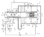
図1に示すように、排気浄化システム1は、エンジン2から排気ガスが供給され、供給された排気ガスを浄化して排出するものであり、内筒3と、内筒3の外側に配設される外筒4とから構成される二重管構造を備えている。外筒4は、有底の筒構造を有しており、内筒3の有する2つの端部のうちでエンジン2に近い端部とは反対側の端部である先端部は、外筒4内に挿入され、外筒4の底面5から離間している。これにより、内筒3の内部空間は、内筒3の外面と外筒4の内面との間の外側空間と連通し、これら内筒3と外筒4との全体で、排気通路10を構成する。
具体的に、排気通路10は、内筒3の内面から構成される第1排気通路11と、内筒3の外面と外筒4の内面とから構成される第2排気通路12と、外筒4の底面5と外筒4の内面とから構成されて、第1排気通路11と第2排気通路12とを連通する第3排気通路13とを有している。更に、排気通路10は、第2排気通路12を通過した排気ガスを排出する第4排気通路14を有している。この排気通路10において、エンジン2からの排気ガスは、第1排気通路11に供給され、次いで、第3排気通路13で折り返されて第2排気通路12に供給され、最後に、第4排気通路14から排出される。このような、排気通路10は、第3排気通路13で排気ガス流路を折り返すようにし、第1排気通路11の外側に第2排気通路12が位置するように構成することで、排気ガス流路を長く形成しつつ、内筒3や外筒4の延びる方向において小型化を実現している。
第1排気通路11において最もエンジン2側に位置する部分には、バーナー20によって燃料が燃焼する燃焼空間15が形成されている。この燃焼空間15は、内筒3の一部である燃焼空間形成壁16によって囲まれている。バーナー20は、燃料を燃焼空間15に供給する燃料供給部21と、燃焼空間15に供給された燃料を着火する点火プラグ22とを備える。バーナー20は、上流側選択還元型触媒29の触媒温度が活性温度よりも低いときや、排気の流れる方向において上流側選択還元型触媒29よりも下流に位置する下流側選択還元型触媒51の触媒温度が活性温度より低いときに駆動される。バーナー20の駆動は、上流側選択還元型触媒29や下流側選択還元型触媒51を加熱するとともに、尿素水をアンモニアに加水分解される程度にまで加熱する。
燃料供給部21は、燃料タンク24と燃焼空間形成壁16に設けられた噴射ノズル23との間をパイプ等の燃料通路25で接続し、燃料ポンプ26によって、燃料タンク24の燃料を噴射ノズル23に圧送する。燃料通路25には、噴射ノズル23と燃料ポンプ26との間に燃料開閉弁27が設けられている。燃料開閉弁27は、バーナー20を駆動するときに限って、燃料通路25を開放し、噴射ノズル23に燃料を供給する。点火プラグ22は、例えばスパークプラグやグロープラグであって、燃焼空間形成壁16に設けられ、噴射ノズル23から噴射された燃料に着火する。燃料は、排気ガスに残存する酸素を酸化剤として燃焼する。なお、噴射ノズル23は、燃料開閉弁27の機能が内蔵されるインジェクターであってもよい。
第1排気通路11には、燃焼空間15の下流側に、排気ガスに含まれる粒子性物質(PM:Particulate Matter)を捕捉するDPF(Diesel Particulate Filter)30が設けられている。DPF30は、例えば耐熱性に優れたセラミックやステンレスを素材としたウォール・フロー・フィルターであり、排気ガスに含まれる粒子性物質を、壁を通過する際に捕捉する。
なお、DPF30が捕捉した粒子性物質は、バーナー20における燃料の燃焼によって昇温した排気ガスが流入することにより焼却される。
なお、DPF30が捕捉した粒子性物質は、バーナー20における燃料の燃焼によって昇温した排気ガスが流入することにより焼却される。
このようなDPF30を構成するフィルタには、ゼオライト、アルミナ、ジルコニア等の上流側選択還元型触媒29を担持することによって、DPF30に、選択還元型システムの機能を持たせることができる。ゼオライトとしては、銅ゼオライト、鉄ゼオライト、銀ゼオライト、亜鉛ゼオライト、コバルトゼオライト等を挙げることができる。排気に含まれるNOxの還元に際して、この上流側選択還元型触媒29は、後述の第2排気通路12に設けられる下流側選択還元型触媒51の補助的な役割を果たす。すなわち、NOxの還元性能は、選択還元型触媒の量が多いほど高くなる。一方で、フィルタの選択還元型触媒を多く、すなわち厚く設け過ぎると、排気ガスが排気通路を流れにくくなり、フィルタの圧力損失が増大する。そこで、ここでの上流側選択還元型触媒29は、下流側選択還元型触媒51の還元に対して補助的な役割を果たす。上流側選択還元型触媒29は、排気ガスによって活性温度以上に加熱されるとともに、冷間始動時や軽負荷運転時において活性温度より低いときにはバーナー20によって活性温度以上に加熱される。
このDPF30に設けられた上流側選択還元型触媒29に用いられる還元剤としては、尿素水が用いられる。このため、第1排気通路11のDPF30の上流側、すなわち燃焼空間15には、尿素水をDPF30の上流側に供給する尿素水供給部31が設けられている。尿素水供給部31は、燃焼空間15からの排気ガスに対して還元剤となる尿素水や加水分解されたアンモニアを添加する上流側添加弁32を備える。上流側添加弁32は、燃焼空間形成壁16に設けられ、排気ガスの流れ方向に尿素水やアンモニアを添加する。
尿素水供給部31は、尿素水タンク33と燃焼空間形成壁16に設けられた上流側添加弁32との間をパイプ等の接続通路34で接続し、尿素水ポンプ35によって、尿素水タンク33の尿素水を上流側添加弁32に圧送する。接続通路34には、上流側添加弁32と尿素水ポンプ35との間に開閉弁36が設けられている。開閉弁36は、接続通路34を開放して上流側添加弁32に尿素水を供給し、また、接続通路34を遮断して上流側添加弁32に対する尿素水の供給を停止する。
尿素水を上流側添加弁32に供給する接続通路34において開閉弁36の下流に位置する部分は、DPF30の選択還元型触媒に添加する尿素水を加熱する上流側用加熱部37として機能する。上流側用加熱部37は、第1排気通路11内の燃焼空間15に位置し、燃焼空間15内での流路の長さが長くなるように、熱伝導性が高い銅やステンレス等のパイプがコイル状や千鳥状に形成された通路であって、尿素水を効率的に加熱する。上流側用加熱部37は、燃焼空間15における燃料がバーナー20によって燃焼することにより、尿素水がアンモニアに加水分解される程度にまで加熱する。上流側添加弁32からは、バーナー20が駆動しているとき、加熱された尿素水又はアンモニアがDPF30よりも上流に添加される。
更に、第1排気通路11には、燃焼空間15に流入する排気ガスのNOx濃度を検出する上流側NOx濃度センサー42と、DPF30の上流側選択還元型触媒29に流入する排気ガスの温度を選択還元型触媒の触媒温度として検出する上流側温度センサー43とが設けられている。
第1排気通路11には、排気の流れる方向においてDPF30の下流側に、排気ガスに含まれるNOxを吸着するNOx吸着材50が設けられている。NOx吸着材50は、NOxを物理的に吸着するフィルタであって、NOx吸着材50を形成する材料は希土類系、アルカリ金属、アルカリ土類金属の酸化物、ゼオライト等である。このNOx吸着材50は、所定温度まで加熱されたときにNOxを放出する。例えば、このNOx吸着材50は、例えば150~250℃程度の温度でNOxを放出する。NOx吸着材50を通過したNOxや再生処理で放出したNOxは、下流側の第2排気通路12に設けられる下流側選択還元型触媒51によって、窒素に変換される。このNOx吸着材50は、選択還元型触媒が活性化する活性温度より低い温度においてもNOxを物理的に吸着することができ、選択還元型触媒が活性化する温度よりも低い冷間始動時や軽負荷運転時にあっても、NOxが大気中に放出されることを防止することができる。
DPF30で粒子性物質が除去された排気ガスは、第3排気通路13で流れの向きが折り返され、次いで、第2排気通路12に供給される。第2排気通路12は、第1排気通路11の外側に位置し、第3排気通路13で折り返された排気ガスが第2排気通路12に流入する。この第2排気通路12は、内筒3の外面と外筒4の内面との間の空間により構成されており、特に燃焼空間15の外側は、上述したDPF30の補助的な上流側選択還元型触媒29に対して、主となる下流側選択還元型触媒51を配設する空間となる。
下流側選択還元型触媒51は、モノリス触媒であって、例えばコージェライト製のハニカム担体に、ゼオライト、バナジウム系、ジルコニア系等をコーティングして構成される。ゼオライトとしては、銅ゼオライト、鉄ゼオライト、亜鉛ゼオライト、コバルトゼオライト等が挙げられる。一般に、下流側選択還元型触媒51は、活性温度より低いときに活性化せず、十分なNOxの浄化能力を有しない。下流側選択還元型触媒51は、排気ガスによって活性温度以上に加熱されるとともに、冷間始動時や軽負荷運転時において、活性温度より低いときにはバーナー20によって活性温度以上に加熱されることになる。下流側選択還元型触媒51は、バーナー20が駆動されると、内筒3の一部である燃焼空間形成壁16を介して加熱或いはバーナー20で加熱された排気ガスにより加熱されることになる。
この下流側選択還元型触媒51にも、還元剤として、例えば尿素水が用いられる。このため、第2排気通路12の下流側選択還元型触媒51の上流側には、還元剤を下流側選択還元型触媒51に供給する尿素水供給部52が設けられている。尿素水供給部52は、第3排気通路13からの排気ガスに対して尿素水や加水分解されたアンモニアを添加する下流側添加弁53を備える。下流側添加弁53は、第2排気通路12を構成する外筒4に設けられ、排気ガスの流れ方向に尿素水又はアンモニアを添加する。
尿素水供給部52は、上述した尿素水供給部31と一部、構成部材を共通化しており、尿素水ポンプ35より上流側は、尿素水供給部31と共通で、尿素水ポンプ35より下流側は、パイプ等の接続通路54で下流側添加弁53と接続される。接続通路54には、下流側添加弁53と尿素水ポンプ35との間に開閉弁55が設けられる。開閉弁55は、接続通路54を開放して、下流側添加弁53の方向に尿素水を供給する。
尿素水を下流側添加弁53に供給する接続通路54の一部は、開閉弁55の下流において、下流側選択還元型触媒51に添加する尿素水を加熱する下流側用加熱部56として機能する。下流側用加熱部56は、上述の上流側用加熱部37と同様に、第1排気通路11内の燃焼空間15に位置している。下流側用加熱部56は、燃焼空間15においてバーナー20によって燃料が燃焼することにより、尿素水を、アンモニアに加水分解される程度にまで加熱する。下流側添加弁53からは、バーナー20が駆動しているとき、加熱された尿素水又は加水分解されたアンモニアが下流側選択還元型触媒51よりも上流に添加される。
更に、第2排気通路12には、下流側選択還元型触媒51の上流側に、下流側選択還元型触媒51に流入する排気ガスのNOx濃度を検出する下流側NOx濃度センサー44と、下流側選択還元型触媒51に流入する排気ガスの温度を下流側選択還元型触媒51の触媒温度として検出する下流側温度センサー45とが設けられている。また、第2排気通路12に設けられた下流側選択還元型触媒51の下流となる第4排気通路14には、最終的に、排気ガス中に含まれるNOx濃度を検出する排出NOx濃度センサー46が設けられる。
図2に示すように、以上のように構成された排気浄化システム1は、マイコン等で構成された制御装置47によって制御される。制御装置47は、ROM、RAM、CPUといった構成を備えている。制御装置47は、ROMに格納された制御プログラムに従って各種センサー41,42,43,44,45,46等から入力された入力値を用いた演算を行って、バーナー20の点火プラグ22の点火制御や尿素水供給部31,52の開閉弁36,55の開閉制御や燃料ポンプ26や尿素水ポンプ35の駆動制御等を行う。
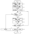
図3を参照して、尿素水を添加する処理の一例について説明する。この処理は、冷間始動時や軽負荷運転時に開始されるとともに繰り返し実行される。
ステップS1において、制御装置47は、エンジン2の吸気通路に設けられた吸入空気量センサー41からの吸入空気量Ga、NOx濃度センサー42,44,46からのNOx濃度Cx1,Cx2,Cx3、温度センサー43,45からの触媒温度Tc1,Tc2を取得する。
ステップS1において、制御装置47は、エンジン2の吸気通路に設けられた吸入空気量センサー41からの吸入空気量Ga、NOx濃度センサー42,44,46からのNOx濃度Cx1,Cx2,Cx3、温度センサー43,45からの触媒温度Tc1,Tc2を取得する。
ステップS2において、制御装置47は、取得した吸入空気量Ga、第1排気通路11の上流側NOx濃度センサー42から取得したNOx濃度Cx1、第1排気通路11の上流側温度センサー43から取得した触媒温度Tc1に基づいて、第1排気通路11のNOx量Gx1を算出する。ステップS3において、NOx量Gx1に基づき、上流側選択還元型触媒29に供給する上流側添加弁32の方向に供給する尿素水の添加量Gu1を算出する。
また、制御装置47は、吸入空気量Ga、第2排気通路12の下流側NOx濃度センサー44から取得したNOx濃度Cx2、第2排気通路12の下流側温度センサー45から取得した触媒温度Tc2に基づいて、第2排気通路12のNOx量Gx2を算出する。ステップS3において、NOx量Gx2に基づき、下流側選択還元型触媒51に供給する下流側添加弁53の方向に供給する尿素水の添加量Gu2を算出する。
ステップS4において、制御装置47は、ステップS1において第1排気通路11の上流側温度センサー43から取得した触媒温度Tc1と第2排気通路12の下流側温度センサー45から取得した触媒温度Tc2の少なくとも1つが活性温度Tca未満であるか否かを判断する。そして、触媒温度Tc1,Tc2の少なくとも1つが活性温度Tca未満のとき、尿素水を加熱するための処理であるステップS5に進む。また、活性温度Tca未満でない場合、すなわち触媒温度Tc1,Tc2が活性温度Tca以上のとき、尿素水をバーナー20で加熱しないステップS9に進む。制御装置47は、このような判断を行うことで、活性温度未満の下流側選択還元型触媒51や上流側選択還元型触媒29に尿素水が供給されてしまい、尿素水に含まれる尿素が結晶化してしまうことを防止する。
触媒温度Tc1,Tc2の少なくとも1つが活性温度Tca未満の場合は、ステップS5において、尿素水の添加量Gu1,Gu2に応じたバーナー20を駆動するための燃料量Gfを算出する。ステップS6において、制御装置47は、燃料の燃料開閉弁27を開弁し、燃料ポンプ26を駆動し、燃料量Gfの分の燃料を噴射ノズル23から噴射する。そして、点火プラグ22を駆動して燃料に着火する。
ステップS7において、制御装置47は、燃料量Gfの演算が連続しているか否かを判断する。すなわち、制御装置47は、燃料量Gfの演算が連続しているか否かを判断することで、バーナー20が駆動し続けているかを判断する。制御装置47は、燃料量Gfの演算が連続しているとき、ステップS8に進み、連続していないとき、ステップS4に戻る。連続していないとき、制御装置47は、ステップS4からの処理(演算)を繰り返す。
ステップS8において、制御装置47は、開閉弁36を開弁し、上流側用加熱部37で加熱された尿素水又は尿素水が加水分解されて生成されたアンモニアを、上流側添加弁32より、DPF30の上流側選択還元型触媒29の手前に添加する。また、開閉弁55を開弁し、下流側用加熱部56で加熱された尿素水又は尿素水が加水分解されて生成されたアンモニアを、下流側添加弁53より、下流側選択還元型触媒51の手前に添加する。
かくして、バーナー20が駆動されることで、尿素水が、燃焼空間15の下流側用加熱部56や上流側用加熱部37において加水分解が促進するように加熱される。更に、DPF30の上流側選択還元型触媒29が活性温度以上に加熱され、第2排気通路12の下流側選択還元型触媒51も燃焼空間形成壁16を介して活性温度以上に加熱される。これにより、尿素水がアンモニアに変換されやすくなり、又は、尿素水が加水分解されてアンモニアが生成されることから、排気ガスの温度や下流側選択還元型触媒51の触媒温度Tc1や上流側選択還元型触媒29の触媒温度Tc2が活性温度Tcaより低い場合であっても、加熱された尿素水やアンモニアの添加が可能となる。これにより、冷間始動時や軽負荷運転時において、NOxが大気中に放出されることを防止することができる。
制御装置47は、ステップS4で既に触媒温度Tc1,Tc2が活性温度Tca以上と判断した場合、ステップS9において、バーナー20を駆動することなく、バーナー20で加熱していない尿素水を添加弁32,53より、上流側選択還元型触媒29や下流側選択還元型触媒51に添加する。このような場合は、既に、下流側選択還元型触媒51や上流側選択還元型触媒29が活性温度以上に十分に加熱されており、バーナー20を駆動するまでもなく、尿素水を添加するだけで加水分解が進み、上流側選択還元型触媒29や下流側選択還元型触媒51にアンモニアが供給されるからである。
ところで、上流側選択還元型触媒29やDPF30を透過した排気ガスのNOxは、NOx吸着材50によって物理的に吸着される。このNOx吸着材50は、触媒温度Tc1,Tc2が活性温度Tcaより低くとも、NOxを吸着する。これにより、選択還元型触媒が活性化する活性温度よりも低い冷間始動時や軽負荷運転時にあっても、NOxが大気中に放出されることを防止することができる。一方で、NOx吸着材50には、NOxの吸着量に限界がある。制御装置47は、排気の流れる方向においてDPF30の下流に位置するNOx吸着材50に対してNOxの吸着量を管理し、吸着量が性能限界値に近い閾値になると、NOx吸着材50の再生処理を開始する。
具体的に、図4に示すように、ステップS11及びステップS12では、上述したステップS1及びステップS2と同様に、制御装置47が吸入空気量センサー41からの吸入空気量Ga、NOx濃度センサー42,44からのNOx濃度Cx1,Cx2、温度センサー43,45からの触媒温度Tc1,Tc2を取得する。制御装置47は、取得した吸入空気量Ga、NOx濃度センサー42,44から取得したNOx濃度Cx1,Cx2、温度センサー43,45から取得した触媒温度Tc1,Tc2に基づいて、第1排気通路11のNOx量Gx1と第2排気通路12のNOx量Gx2とを算出する。
第1排気通路11のNOx量Gx1は、燃焼空間15のNOx量Gx1であり、エンジン2から供給された排気ガスであって排気浄化システム1による浄化処理前の排気ガスにおけるNOx量である。また、第2排気通路12のNOx量Gx2は、上流側選択還元型触媒29及びNOx吸着材50を通過した後のNOx量となる。
ステップS13において、制御装置47は、浄化処理前のNOx量Gx1からNOx吸着材50を通過した後のNOx量Gx2を減算する処理を行い、NOx吸着材50に吸着したNOx量Gx3を算出する。なお、NOx量Gx3を算出するにあたって、上流側選択還元型触媒29で処理されたNOx量を考慮する場合は、NOx量Gx1から、上流側選択還元型触媒29で処理されたNOx量とNOx量Gx2とが減算される。上流側選択還元型触媒29で処理されたNOx量は、例えば、上流側温度センサー43からの触媒温度Tc1等に基づきテーブルを参照して算出することができる。
ステップS14において、制御装置47は、前回までのNOx量Gx3の積算値に今回のNOx量Gx3を積算して今回の積算値GxTを算出する。ステップS15において、制御装置47は、今回の積算値GxTが所定の吸着量を超えたか否かを判断し、今回の積算値GxTが所定の吸着量を超えるまで、ステップS11からステップS14までの処理を繰り返す。そして、制御装置47は、今回の積算値GxTが所定の吸着量を超えたと判断したとき、ステップS16に進む。ステップS16において、制御装置47は、バーナー20を駆動し、DPF30を介してNOx吸着材50を加熱し、吸着したNOxをNOx吸着材50から放出する再生処理を行う。なお、放出されたNOxは、下流側選択還元型触媒51によって処理される。
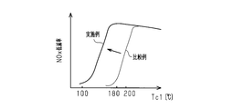
図5は、触媒温度とNOx低減率との関係の一例を示すグラフであって、NOx低減率について行った実験の結果を示すグラフである。図5において、実施例のNOx低減率は、上記排気浄化システム1によって得られた値である。比較例のNOx低減率は、上記排気浄化システム1から加熱部37,56、および、NOx吸着材50が省略された排気浄化システムによって得られた値である。図5に示すように、比較例においては、冷間始動時や軽負荷運転時における触媒温度の温度範囲である100℃~180℃の範囲では、NOx低減率が著しく低い。一方、実施例においては、触媒温度が100℃~180℃の範囲においてもNOxが低減されることが認められる。また、200℃以下の各温度において比較例よりもNOx低減率が高いことが認められた。
第1実施形態の排気浄化システム1によれば、以下に列挙する効果が得られる。
(1)排気浄化システム1では、バーナー20の駆動によって尿素水が加熱されアンモニアに変換されやすくなる。したがって、選択還元型触媒29,51の触媒温度Tc1,Tc2が活性温度Tcaより低くとも、排気ガスに対して、燃焼空間15の加熱部37、56で加熱された尿素水や加水分解されたアンモニアを供給することができる。その結果、NOxの低減量が高まる。
(1)排気浄化システム1では、バーナー20の駆動によって尿素水が加熱されアンモニアに変換されやすくなる。したがって、選択還元型触媒29,51の触媒温度Tc1,Tc2が活性温度Tcaより低くとも、排気ガスに対して、燃焼空間15の加熱部37、56で加熱された尿素水や加水分解されたアンモニアを供給することができる。その結果、NOxの低減量が高まる。
(2)排気浄化システム1では、下流側選択還元型触媒51の上流に位置するNOx吸着材50が触媒温度Tc1,Tc2が活性温度Tcaより低くても、NOxを吸着する。したがって、選択還元型触媒が活性化する活性温度よりも低い冷間始動時や軽負荷運転時にあっても、NOxが大気中に放出されることを防止することができる。
(3)バーナー20の下流にDPF30が配設されていることで、バーナー20の駆動に伴う粒子性物質をDPF30にて捕捉することができる。その結果、バーナー20の駆動に起因した粒子性物質の排出量の増加が抑えられる。
(4)DPF30には、上流側選択還元型触媒29が一体的に設けられていることから、NOx吸着材50や下流側選択還元型触媒51の上流側で、NOxを低減することができ、NOx吸着材50や下流側選択還元型触媒51の負担を軽減することができる。
(5)加熱部37、56で尿素水を加熱するためバーナー20を駆動したときには、同時に、上流側選択還元型触媒29が加熱される。更に、同時に、下流側選択還元型触媒51が燃焼空間形成壁16を介して加熱される。これにより、選択還元型触媒29,51の触媒温度Tc1,Tc2が活性温度Tcaに到達するまでに要する時間を短縮することができる。
(6)バーナー20は、選択還元型触媒29,51の触媒温度Tc1,Tc2が活性温度Tca未満のときに限って駆動される。したがって、バーナー20で尿素水を加熱するための燃料消費を最低限に抑えることができる。
(7)触媒温度Tc1,Tc2が活性温度Tca未満のときに選択還元型触媒29,51に供給されたアンモニアは、そのまま選択還元型触媒29,51に保持され、触媒温度Tc1,Tc2が活性温度Tcaに達したとき、直ちに保持されたアンモニアによって窒素に変換することができる。
(第2実施形態)
(第2実施形態)
図6を参照して、排気浄化システムの第2実施形態について説明する。なお、第2実施形態の排気浄化システムは、第1実施形態の排気浄化システムと主要な構成が同じであるため、第2実施形態では、第1実施形態と異なる部分について詳細に説明し、第1実施形態と同様の部分については同様の符号を付すことで詳細な説明は省略する。
図6に示すように、この排気浄化システムは、NOx吸着材50の外側に、下流側バーナー60が設けられている。この下流側バーナー60は、燃料を第2排気通路12に供給する燃料供給部61と、第2排気通路12に供給された燃料を着火する点火プラグ62とを備える。燃料供給部61を構成する複数の構成要素の一部は、上述した燃料供給部21と共通である。すなわち、燃料供給部61において燃料ポンプ26よりも上流に位置する構成要素は、燃料供給部21と共通であり、燃料ポンプ26よりも下流に位置するパイプ等の接続通路63は、噴射ノズル64と接続されている。接続通路63において、噴射ノズル64と燃料ポンプ26との間には、燃料開閉弁65が設けられている。燃料開閉弁65は、接続通路63を開放して噴射ノズル64に燃料を供給し、また、接続通路63を遮断して噴射ノズル64に対する燃料の供給を停止する。点火プラグ62は、内筒3の第2排気通路12の部分に設けられ、噴射ノズル64から噴射された燃料に着火する。燃料は、排気ガスに残存する酸素を酸化剤として燃焼する。
また、図6に示すように、DPF30と上流側選択還元型触媒29とを一体化するだけでなく、更に、NOx吸着材50も一体化し、構成の簡素化や部品点数の削減を図ることができる。この場合、DPF30の上流側の面に、上流側選択還元型触媒29を担持させ、下流側の面に、NOx吸着材50を担持させる。そして、DPF30は、上流側選択還元型触媒29とNOx吸着材50が重ならないように形成する。これにより、フィルタの圧力損失の増大を防ぐことができる。
第2実施形態の排気浄化システムによれば、第1実施形態に記載した(1)~(7)に準ずる効果に加えて、以下に列挙する効果が得られる。
(8)下流側バーナー60は、第2排気通路12の下流の下流側選択還元型触媒51の触媒温度が活性温度より低いときに駆動され、下流側選択還元型触媒51を加熱することができるとともに、下流側添加弁53から添加された尿素水を加熱し加水分解によりアンモニアに変換する。したがって、下流側選択還元型触媒51の触媒温度Tc2が活性温度Tcaに到達するまでに要する時間を更に短縮することができる。
(8)下流側バーナー60は、第2排気通路12の下流の下流側選択還元型触媒51の触媒温度が活性温度より低いときに駆動され、下流側選択還元型触媒51を加熱することができるとともに、下流側添加弁53から添加された尿素水を加熱し加水分解によりアンモニアに変換する。したがって、下流側選択還元型触媒51の触媒温度Tc2が活性温度Tcaに到達するまでに要する時間を更に短縮することができる。
(9)下流側バーナー60は、下流側選択還元型触媒51を再生するときに、内筒3を介してNOx吸着材50を加熱する。これにより、NOx吸着材50に吸着したNOxが下流側に放出される。放出されたNOxは、下流側選択還元型触媒51によって除去することができる。
(10)DPF30には、上流側選択還元型触媒29とNOx吸着材50とが一体的に設けられていることから、部品点数の削減とともに小型化を実現することができる。DPF30に上流側選択還元型触媒29とNOx吸着材50とを一体的に設けた場合であっても、上流側選択還元型触媒29とNOx吸着材50とは重ならないように設けられているので、フィルタの圧力損失を防ぐことができる。
なお、上記第1及び第2実施形態は、以下のように変更してもよい。
・NOx吸着材50の位置は、排気の流れる方向において、DPF30よりも下流であれば特に限定されるものではない。例えば、NOx吸着材50は、第2排気通路12において、下流側選択還元型触媒51の直前に配置することもできる。
・NOx吸着材50の位置は、排気の流れる方向において、DPF30よりも下流であれば特に限定されるものではない。例えば、NOx吸着材50は、第2排気通路12において、下流側選択還元型触媒51の直前に配置することもできる。
・排気通路10は、内筒3と外筒4とで構成された二重管構造に限定されるものではない。例えば、排気通路10は、1本の筒体によって構成されて、排気通路10の一端部がエンジン2に接続されて、排気の流れる方向において上流側から順に、バーナー20、DPF30、NOx吸着材50、下流側選択還元型触媒51が配置される構成であってもよい。この際、排気通路10を構成する筒体は、直線状をなしていてもよいし、少なくとも一部が湾曲したものであってもよい。
・DPF30に上流側選択還元型触媒29を担持させた構成を説明したが、NOx吸着材50や下流側選択還元型触媒51が十分にNOxを除去する構成であれば、排気浄化システムにおいて上流側選択還元型触媒29が省略されてもよい。
・NOx吸着材50は、NOxを物理的に吸着するものではなく、DPNR触媒(Diesel Particulate-NOx Reduction)を用いたものであってもよい。この場合、THC、COに加え微粒子とNOxとを同時低減することができ、DPF30を省略することも可能である。なお、NOx吸着材50は、NOxを物理的に吸着する構造体と、DPNR触媒を用いた構造体との組み合わせであってもよい。
・DPF30の上流に酸化触媒(DOC:Diesel Oxidation Catalyst)を配置するようにしてもよい。下流側選択還元型触媒51の下流に、アンモニアを酸化するアンモニア酸化触媒をさらに備えてもよい。
・触媒温度Tc1,Tc2が活性温度Tcaに到達しているときに、バーナー20が駆動されてもよい。こうした構成においても、燃料量Gfは、尿素水の添加量Gu1,Gu2に応じて制御されることが好ましい。
・尿素水の添加量Gu1,Gu2に関わらず燃料量Gfが一定であってもよい。こうした構成であっても、尿素水がアンモニアに変換されるやすくなる。
・尿素水の添加量Gu1,Gu2に関わらず燃料量Gfが一定であってもよい。こうした構成であっても、尿素水がアンモニアに変換されるやすくなる。
・尿素水タンク33内の尿素水の温度を検出するセンサーの検出値に基づいて燃料量Gfが調整されてもよい。こうした構成によれば、バーナー20の駆動にともなう燃料消費量がさらに抑えられる。
・加熱部37、56は、燃焼空間15に位置していればよく、その形状はコイル状や螺旋状の形状に限られるものではない。
・加熱部37、56は、燃焼空間15に位置していればよく、その形状はコイル状や螺旋状の形状に限られるものではない。
・尿素水供給部31,52は、加熱部37,56と添加弁32,53との間にパイプを覆うように断熱材を設け、加熱された尿素水の温度低下を防止してもよい。
・バーナー20,60には、燃料と空気との混合気が生成されるように、噴射ノズル23,64の上流にて空気を供給する空気供給部を設けてもよい。また、バーナー20,60は、燃料と空気とを予め混合した予混合気を供給する構成であってもよい。
・図1の排気浄化システム1において、図6に示すように、DPF30と上流側選択還元型触媒29とNOx吸着材50とを一体化したフィルタを用いてもよい。また、図6の排気浄化システム1において、上流側選択還元型触媒29が一体化されたDPF30とNOx吸着材50とを別体としてもよい。
Claims (7)
- 排気ガスが流れる排気通路と、
前記排気通路に配置されたバーナーであって、前記バーナーにおける燃料の燃焼空間が前記排気通路内の一部である前記バーナーと、
前記排気通路において前記燃焼空間よりも下流に位置して前記排気ガスに含まれる窒素酸化物を吸着するNOx吸着材と、
前記排気通路において前記NOx吸着材よりも下流に位置する選択還元型触媒と、
前記排気通路において前記選択還元型触媒と前記燃焼空間との間に位置する添加弁と、
前記添加弁に接続されて前記添加弁に向かう尿素水が流れる接続通路であって、前記接続通路の一部が前記燃焼空間を通る前記接続通路と、
を備える排気浄化システム。 - 更に、前記排気通路には、前記バーナーと前記NOx吸着材との間に、DPFを備える
請求項1に記載の排気浄化システム。 - 前記選択還元型触媒が下流側選択還元型触媒であり、
前記添加弁が下流側添加弁であり、
前記接続通路が前記下流側添加弁用の接続通路であり、
前記DPFには、前記排気通路において前記下流側選択還元型触媒よりも上流に位置する上流側選択還元型触媒が一体化され、
更に、前記排気通路において前記上流側選択還元型触媒よりも上流に位置する上流側添加弁と、
前記上流側添加弁に接続されて前記上流側添加弁に向かう尿素水が流れる前記上流側添加弁用の接続通路であって、前記上流側の接続通路の一部が前記燃焼空間を通る前記上流側添加弁用の接続通路と、
を備える請求項2に記載の排気浄化システム。 - 前記DPFには、上流側の面に、前記上流側選択還元型触媒が一体的に設けられ、下流側の面に、前記NOx吸着材が一体的に設けられている
請求項3に記載の排気浄化システム。 - 前記排気通路は、前記燃焼空間を形成する燃焼空間形成壁を備え、前記燃焼空間形成壁が、前記選択還元型触媒が位置する空間と前記燃焼空間とを区画し、
前記選択還元型触媒は、前記バーナーによって前記燃料が燃焼することにより、前記燃焼空間形成壁を介して加熱される
請求項1又は2記載の排気浄化システム。 - 更に、前記選択還元型触媒の触媒温度を取得し、前記取得された触媒温度が前記選択還元型触媒の活性温度未満である場合に前記バーナーを駆動する制御装置を備える
請求項1,2,5の何れか1項記載の排気浄化システム。 - 前記バーナーは、
前記排気通路において前記NOx吸着材よりも上流に位置する上流側のバーナーであり、
更に、前記排気通路において、前記NOx吸着材と前記選択還元型触媒との間に下流側のバーナーが更に設けられ、
前記制御装置は、前記取得された触媒温度が前記選択還元型触媒の活性温度未満であるとき、前記下流側のバーナーを駆動する
請求項6に記載の排気浄化システム。
Priority Applications (2)
| Application Number | Priority Date | Filing Date | Title |
|---|---|---|---|
| US16/078,465 US10519829B2 (en) | 2016-02-22 | 2016-02-22 | Exhaust purification system |
| PCT/JP2016/055052 WO2017145235A1 (ja) | 2016-02-22 | 2016-02-22 | 排気浄化システム |
Applications Claiming Priority (1)
| Application Number | Priority Date | Filing Date | Title |
|---|---|---|---|
| PCT/JP2016/055052 WO2017145235A1 (ja) | 2016-02-22 | 2016-02-22 | 排気浄化システム |
Publications (1)
| Publication Number | Publication Date |
|---|---|
| WO2017145235A1 true WO2017145235A1 (ja) | 2017-08-31 |
Family
ID=59685139
Family Applications (1)
| Application Number | Title | Priority Date | Filing Date |
|---|---|---|---|
| PCT/JP2016/055052 Ceased WO2017145235A1 (ja) | 2016-02-22 | 2016-02-22 | 排気浄化システム |
Country Status (2)
| Country | Link |
|---|---|
| US (1) | US10519829B2 (ja) |
| WO (1) | WO2017145235A1 (ja) |
Cited By (2)
| Publication number | Priority date | Publication date | Assignee | Title |
|---|---|---|---|---|
| US10519829B2 (en) | 2016-02-22 | 2019-12-31 | Hino Motors, Ltd. | Exhaust purification system |
| WO2021095305A1 (ja) * | 2019-11-12 | 2021-05-20 | 日立造船株式会社 | 整流装置、加水分解装置、及び脱硝設備 |
Families Citing this family (1)
| Publication number | Priority date | Publication date | Assignee | Title |
|---|---|---|---|---|
| KR102231725B1 (ko) | 2020-01-30 | 2021-03-24 | (주)케이랩스 | 3d 프린팅 장치 |
Citations (3)
| Publication number | Priority date | Publication date | Assignee | Title |
|---|---|---|---|---|
| JP2005507985A (ja) * | 2001-11-06 | 2005-03-24 | ローベルト ボツシユ ゲゼルシヤフト ミツト ベシユレンクテル ハフツング | 排ガスの窒素酸化物を減少させる方法及び装置 |
| JP2012082804A (ja) * | 2010-10-14 | 2012-04-26 | Mitsubishi Heavy Ind Ltd | 舶用排気ガス脱硝装置 |
| JP2014527592A (ja) * | 2011-08-04 | 2014-10-16 | テネコ・オートモーティヴ・オペレーティング・カンパニー・インコーポレーテッド | 炭化水素希薄NOx触媒を備えた排気処理システム |
Family Cites Families (8)
| Publication number | Priority date | Publication date | Assignee | Title |
|---|---|---|---|---|
| JP3211139B2 (ja) | 1995-06-30 | 2001-09-25 | スズキ株式会社 | 内燃機関の潤滑通路構造 |
| DE19855338A1 (de) | 1998-12-01 | 2000-06-08 | Bosch Gmbh Robert | Vorrichtung zum Einbringen eines Reduktionsmittels in einen Abgasrohrabschnitt einer Brennkraftmaschine |
| JP2009013932A (ja) | 2007-07-06 | 2009-01-22 | Hino Motors Ltd | 排気浄化装置 |
| JP5158214B2 (ja) | 2009-01-09 | 2013-03-06 | トヨタ自動車株式会社 | 内燃機関の排気浄化装置 |
| US20110289906A1 (en) | 2009-04-27 | 2011-12-01 | Nicholas Morley | Miniature Regeneration Unit |
| US20100269492A1 (en) | 2009-04-27 | 2010-10-28 | Tenneco Automotive Operating Company Inc. | Diesel aftertreatment system |
| JP5952533B2 (ja) | 2011-06-28 | 2016-07-13 | 日野自動車株式会社 | 排ガス浄化装置 |
| WO2017145235A1 (ja) | 2016-02-22 | 2017-08-31 | 日野自動車 株式会社 | 排気浄化システム |
-
2016
- 2016-02-22 WO PCT/JP2016/055052 patent/WO2017145235A1/ja not_active Ceased
- 2016-02-22 US US16/078,465 patent/US10519829B2/en not_active Expired - Fee Related
Patent Citations (3)
| Publication number | Priority date | Publication date | Assignee | Title |
|---|---|---|---|---|
| JP2005507985A (ja) * | 2001-11-06 | 2005-03-24 | ローベルト ボツシユ ゲゼルシヤフト ミツト ベシユレンクテル ハフツング | 排ガスの窒素酸化物を減少させる方法及び装置 |
| JP2012082804A (ja) * | 2010-10-14 | 2012-04-26 | Mitsubishi Heavy Ind Ltd | 舶用排気ガス脱硝装置 |
| JP2014527592A (ja) * | 2011-08-04 | 2014-10-16 | テネコ・オートモーティヴ・オペレーティング・カンパニー・インコーポレーテッド | 炭化水素希薄NOx触媒を備えた排気処理システム |
Cited By (2)
| Publication number | Priority date | Publication date | Assignee | Title |
|---|---|---|---|---|
| US10519829B2 (en) | 2016-02-22 | 2019-12-31 | Hino Motors, Ltd. | Exhaust purification system |
| WO2021095305A1 (ja) * | 2019-11-12 | 2021-05-20 | 日立造船株式会社 | 整流装置、加水分解装置、及び脱硝設備 |
Also Published As
| Publication number | Publication date |
|---|---|
| US20190024555A1 (en) | 2019-01-24 |
| US10519829B2 (en) | 2019-12-31 |
Similar Documents
| Publication | Publication Date | Title |
|---|---|---|
| US11815000B2 (en) | Exhaust gas treatment system with improved low temperature performance | |
| US20130111886A1 (en) | Electronically Heated NOx Adsorber Catalyst | |
| US20140311123A1 (en) | Electrically heated doc using hcscr cold start nox controls | |
| WO2009017639A1 (en) | Exhaust treatment system with an oxidation device for no2 control | |
| US12404794B2 (en) | Valve arrangement for split-flow close-coupled catalyst | |
| JP5158214B2 (ja) | 内燃機関の排気浄化装置 | |
| JP6586377B2 (ja) | 排気浄化装置 | |
| CN219754632U (zh) | 用于车辆的排气系统 | |
| US10519829B2 (en) | Exhaust purification system | |
| JP5282568B2 (ja) | 排気ガス浄化方法及び排気ガス浄化システム | |
| JP6352115B2 (ja) | 排気浄化システム | |
| JP5614004B2 (ja) | 触媒昇温装置 | |
| JP6469457B2 (ja) | 排気浄化装置 | |
| JP6352114B2 (ja) | 排気浄化システム | |
| JP6400457B2 (ja) | 排気浄化装置 | |
| US10920646B2 (en) | Exhaust gas purification system | |
| JP6461585B2 (ja) | 排気浄化装置 | |
| WO2017145234A1 (ja) | 排気浄化システム | |
| JP2022054622A (ja) | 内燃機関の排気浄化システム | |
| JP7298575B2 (ja) | 内燃機関の排気浄化システム | |
| JP7354976B2 (ja) | 内燃機関の排気浄化システム | |
| JP2005105940A (ja) | エンジンの排気浄化装置 | |
| JP2018044498A (ja) | 排気浄化装置及び排気浄化方法 | |
| JP6437314B2 (ja) | 排気浄化装置 | |
| JP2026052410A (ja) | 内燃機関の制御装置 |
Legal Events
| Date | Code | Title | Description |
|---|---|---|---|
| NENP | Non-entry into the national phase |
Ref country code: DE |
|
| 121 | Ep: the epo has been informed by wipo that ep was designated in this application |
Ref document number: 16891394 Country of ref document: EP Kind code of ref document: A1 |
|
| 122 | Ep: pct application non-entry in european phase |
Ref document number: 16891394 Country of ref document: EP Kind code of ref document: A1 |
|
| NENP | Non-entry into the national phase |
Ref country code: JP |