WO2017141592A1 - 燃料噴射弁 - Google Patents
燃料噴射弁 Download PDFInfo
- Publication number
- WO2017141592A1 WO2017141592A1 PCT/JP2017/000938 JP2017000938W WO2017141592A1 WO 2017141592 A1 WO2017141592 A1 WO 2017141592A1 JP 2017000938 W JP2017000938 W JP 2017000938W WO 2017141592 A1 WO2017141592 A1 WO 2017141592A1
- Authority
- WO
- WIPO (PCT)
- Prior art keywords
- wall
- nozzle hole
- cross
- sectional shape
- axis
- Prior art date
- Legal status (The legal status is an assumption and is not a legal conclusion. Google has not performed a legal analysis and makes no representation as to the accuracy of the status listed.)
- Ceased
Links
Images


Classifications
-
- F—MECHANICAL ENGINEERING; LIGHTING; HEATING; WEAPONS; BLASTING
- F02—COMBUSTION ENGINES; HOT-GAS OR COMBUSTION-PRODUCT ENGINE PLANTS
- F02M—SUPPLYING COMBUSTION ENGINES IN GENERAL WITH COMBUSTIBLE MIXTURES OR CONSTITUENTS THEREOF
- F02M61/00—Fuel-injectors not provided for in groups F02M39/00 - F02M57/00 or F02M67/00
- F02M61/16—Details not provided for in, or of interest apart from, the apparatus of groups F02M61/02 - F02M61/14
- F02M61/18—Injection nozzles, e.g. having valve seats; Details of valve member seated ends, not otherwise provided for
- F02M61/1806—Injection nozzles, e.g. having valve seats; Details of valve member seated ends, not otherwise provided for characterised by the arrangement of discharge orifices, e.g. orientation or size
- F02M61/184—Discharge orifices having non circular sections
-
- F—MECHANICAL ENGINEERING; LIGHTING; HEATING; WEAPONS; BLASTING
- F02—COMBUSTION ENGINES; HOT-GAS OR COMBUSTION-PRODUCT ENGINE PLANTS
- F02M—SUPPLYING COMBUSTION ENGINES IN GENERAL WITH COMBUSTIBLE MIXTURES OR CONSTITUENTS THEREOF
- F02M51/00—Fuel-injection apparatus characterised by being operated electrically
- F02M51/06—Injectors peculiar thereto with means directly operating the valve needle
- F02M51/061—Injectors peculiar thereto with means directly operating the valve needle using electromagnetic operating means
- F02M51/0614—Injectors peculiar thereto with means directly operating the valve needle using electromagnetic operating means characterised by arrangement of electromagnets or fixed armature
-
- F—MECHANICAL ENGINEERING; LIGHTING; HEATING; WEAPONS; BLASTING
- F02—COMBUSTION ENGINES; HOT-GAS OR COMBUSTION-PRODUCT ENGINE PLANTS
- F02M—SUPPLYING COMBUSTION ENGINES IN GENERAL WITH COMBUSTIBLE MIXTURES OR CONSTITUENTS THEREOF
- F02M61/00—Fuel-injectors not provided for in groups F02M39/00 - F02M57/00 or F02M67/00
- F02M61/04—Fuel-injectors not provided for in groups F02M39/00 - F02M57/00 or F02M67/00 having valves, e.g. having a plurality of valves in series
- F02M61/10—Other injectors with elongated valve bodies, i.e. of needle-valve type
-
- F—MECHANICAL ENGINEERING; LIGHTING; HEATING; WEAPONS; BLASTING
- F02—COMBUSTION ENGINES; HOT-GAS OR COMBUSTION-PRODUCT ENGINE PLANTS
- F02M—SUPPLYING COMBUSTION ENGINES IN GENERAL WITH COMBUSTIBLE MIXTURES OR CONSTITUENTS THEREOF
- F02M61/00—Fuel-injectors not provided for in groups F02M39/00 - F02M57/00 or F02M67/00
- F02M61/16—Details not provided for in, or of interest apart from, the apparatus of groups F02M61/02 - F02M61/14
- F02M61/18—Injection nozzles, e.g. having valve seats; Details of valve member seated ends, not otherwise provided for
- F02M61/1886—Details of valve seats not covered by groups F02M61/1866 - F02M61/188
Definitions
- the present disclosure relates to a fuel injection valve.
- Patent Document 1 includes a nozzle body having a nozzle hole whose cross-sectional area expands from an inner opening to an outer opening, and has a diameter on an inner wall that forms a nozzle hole passage that connects the inner opening and the outer opening of the nozzle hole.
- a fuel injection valve having a protrusion formed inward is described.
- the fuel flowing through the nozzle hole passage forms the nozzle hole passage because the fuel before flowing into the inner opening flows from a direction non-parallel to the nozzle hole axis connecting the center of the inner opening and the center of the outer opening.
- a liquid film of fuel is formed on a part of the inner wall.
- a protrusion is provided on the inner wall where the fuel liquid film is formed so that the fuel liquid film spreads in the circumferential direction along the inner wall of the nozzle hole passage.
- the range in which the liquid film of fuel spreads changes, the range of fuel spread in the combustion chamber, the spray shape, and the like change. For this reason, there is a concern that the spray characteristics of the fuel injected from the nozzle hole change each time the fuel is injected.
- This disclosure is intended to provide a fuel injection valve that improves the stability of fuel spray characteristics.
- the fuel injection valve according to the first aspect of the present disclosure includes a nozzle body having an injection hole capable of injecting fuel and a valve seat formed around the inner opening of the injection hole.
- the fuel injection valve is provided so as to be able to come into contact with the valve seat.
- the fuel injection valve regulates the fuel flow between the inside and outside of the nozzle body via the nozzle hole and is separated from the valve seat.
- permits the flow of the fuel inside the said nozzle body and the exterior via the said nozzle hole is further provided.
- the fuel injection valve further includes a drive unit capable of reciprocating the needle.
- the nozzle hole is formed so that a cross-sectional area of the inner opening is smaller than a cross-sectional area of the outer opening of the nozzle hole.
- the direction in which the needle reciprocating along the central axis of the nozzle body moves so as to contact the valve seat is the valve closing direction of the central axis.
- the nozzle hole passage of the nozzle hole communicating the inner opening and the outer opening includes a first inner wall located on the valve closing direction side of the nozzle hole axis of the nozzle hole, and the valve closing of the nozzle hole shaft.
- the second inner wall is formed on the side opposite to the direction side and formed closer to the nozzle hole axis than the first inner wall.
- FIG. 2 is a sectional view taken along line II-II in FIG. It is the III section enlarged view of FIG.
- FIG. 4 is a sectional view taken along line IV-IV in FIG. 3;
- FIG. 5 is a cross-sectional view taken along line VV in FIG. It is the VI section enlarged view of FIG.
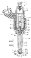
- FIG. 1 shows a cross-sectional view of a fuel injection valve 1 according to the first embodiment.
- the valve closing direction in which the needle 40 moves so as to contact the valve seat 306 along the central axis CA30 of the injection nozzle 30 included in the nozzle body 20 and the needle 40 from the valve seat 306 are illustrated.
- the valve opening direction which is a direction which moves so that it may space apart is illustrated.
- the fuel injection valve 1 is used in a fuel injection device of a direct injection engine (not shown), and injects and supplies gasoline as fuel to the direct injection engine.
- the fuel injection valve 1 includes a nozzle body 20, a needle 40, a movable core 47, a fixed core 44, a coil 38, springs 24 and 26, and the like.
- the movable core 47, the fixed core 44, and the coil 38 correspond to a “drive unit” described in the claims.
- the nozzle body 20 includes a first cylinder member 21, a second cylinder member 22, a third cylinder member 23, an injection nozzle 30, and the like.
- the first cylinder member 21, the second cylinder member 22, and the third cylinder member 23 are all substantially cylindrical members, and are coaxial in the order of the first cylinder member 21, the second cylinder member 22, and the third cylinder member 23. And are connected to each other.
- the injection nozzle 30 is provided at the end of the first cylinder member 21 opposite to the second cylinder member 22.
- the injection nozzle 30 is a bottomed cylindrical member and is welded to the first cylindrical member 21.
- the injection nozzle 30 is subjected to a quenching process so as to have a predetermined hardness.
- the injection nozzle 30 is formed of an injection part 301 and a cylinder part 302.
- the injection unit 301 is a hollow hemispherical part centered on a point on the central axis CA30 of the injection nozzle 30.
- the inner wall surface 303 of the injection part 301 is formed in a spherical shape.
- the inner wall surface 303 forms a sack 304 in which the fuel injected from the injection hole once stays.
- the outer wall surface 305 of the injection part 301 protrudes in the direction of the central axis CA30.
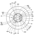
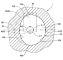
- the injection unit 301 has a plurality of injection holes that communicate the inside and the outside of the nozzle body 20. In the present embodiment, as shown in FIG. 2, six nozzle holes 31, 32, 33, 34, 35, and 36 are arranged in the circumferential direction.
- Each of the nozzle holes 31, 32, 33, 34, 35, 36 has a nozzle hole axis HC 31, which is set in the same direction as the direction in which the processing tool for processing the nozzle hole is advanced when the nozzle hole is processed. It has HC32, HC33, HC34, HC35, HC36.
- the nozzle hole 31 includes an inner opening 311 that is an opening on the inner wall surface 303, an outer opening 312 that is an opening on the outer wall surface 305, and a nozzle hole passage 310 that connects the inner opening 311 and the outer opening 312.
- the nozzle hole 31 has a cross-sectional shape perpendicular to the nozzle hole axis HC31 formed from a curve.
- the nozzle hole 32 includes an inner opening 321 that is an opening on the inner wall surface 303, an outer opening 322 that is an opening on the outer wall surface 305, and a nozzle hole passage 320 that communicates the inner opening 321 and the outer opening 322.
- the nozzle hole 32 has a curved cross-sectional shape perpendicular to the nozzle hole axis HC32.
- the nozzle hole 33 includes an inner opening 331 that is an opening on the inner wall surface 303, an outer opening 332 that is an opening on the outer wall surface 305, a nozzle hole passage 330 that communicates the inner opening 331 and the outer opening 332, and the like.
- the nozzle hole 33 has a cross-sectional shape perpendicular to the nozzle hole axis HC33 formed from a curve.
- the nozzle hole 34 includes an inner opening 341 that is an opening on the inner wall surface 303, an outer opening 342 that is an opening on the outer wall surface 305, and a nozzle hole passage 340 that communicates the inner opening 341 and the outer opening 342.
- the nozzle hole 34 has a cross-sectional shape perpendicular to the nozzle hole axis HC34 formed from a curve.
- the nozzle hole 35 includes an inner opening 351 that is an opening on the inner wall surface 303, an outer opening 352 that is an opening on the outer wall surface 305, a nozzle hole passage 350 that communicates the inner opening 351 and the outer opening 352, and the like.
- the nozzle hole 35 has a cross-sectional shape perpendicular to the nozzle hole axis HC35 formed from a curve.
- the nozzle hole 36 includes an inner opening 361 that is an opening on the inner wall surface 303, an outer opening 362 that is an opening on the outer wall surface 305, and a nozzle hole passage 360 that communicates the inner opening 361 and the outer opening 362.
- the nozzle hole 36 has a curved cross-sectional shape perpendicular to the nozzle hole axis HC36.
- An annular valve seat 306 that can contact the needle 40 is formed on the inner wall surface 303. The detailed shape of the nozzle hole will be described later.
- the cylinder part 302 is provided so as to surround the radially outer side of the injection part 301 and extend on the opposite side to the direction in which the outer wall surface 305 of the injection part 301 protrudes.
- the other end of the cylindrical portion 302 is connected to the first cylindrical member 21.
- the needle 40 is accommodated in the nozzle body 20 so as to be reciprocally movable.
- the needle 40 includes a shaft portion 41, a seal portion 42, a large diameter portion 43, and the like.
- the shaft part 41 is a cylindrical bar-shaped part.
- a sliding portion 45 is provided between the shaft portion 41 and the seal portion 42.
- the sliding portion 45 is a substantially cylindrical portion, and a part of the outer wall 451 is chamfered.
- the sliding part 45 is slidable with the inner wall of the injection nozzle 30 at a portion where the outer wall 451 is not chamfered. Thereby, the needle 40 is guided to reciprocate at the tip portion on the valve seat 306 side.
- the shaft portion 41 has a hole 46 that connects the inner wall and the outer wall of the shaft portion 41 at the end opposite to the side where the sliding portion 45 is provided.
- the seal portion 42 is provided at the end of the shaft portion 41 on the valve seat 306 side so as to be able to contact the valve seat 306.
- the seal portion 42 and the valve seat 306 come into contact with each other, the flow of fuel inside and outside the nozzle body 20 through the nozzle holes 31, 32, 33, 34, 35, 36 is restricted. Further, when the seal portion 42 and the valve seat 306 are separated from each other, the fuel flow between the nozzle body 20 and the outside through the nozzle holes 31, 32, 33, 34, 35, 36 is permitted.
- the large diameter portion 43 is provided on the opposite side of the shaft portion 41 from the seal portion 42.
- the large diameter portion 43 has an outer diameter larger than the outer diameter of the shaft portion 41.
- An end surface of the large diameter portion 43 on the valve seat 306 side is formed so as to be able to contact the movable core 47.
- the needle 40 has a sliding portion 45 that slides on the inner wall of the injection nozzle 30 and a shaft portion 41 that is supported by the inner wall of the second cylindrical member 22 via the movable core 47. Thereby, the reciprocating movement of the needle 40 in the nozzle body 20 is guided.
- the movable core 47 is a substantially cylindrical member that has been subjected to a magnetic stabilization process.
- the movable core 47 is provided on the jet nozzle 30 side of the large diameter portion 43 so as to be able to reciprocate.
- the movable core 47 has a through hole 49 in the approximate center. The shaft portion 41 of the needle 40 is inserted into the through hole 49.
- the fixed core 44 is a substantially cylindrical member that has been subjected to a magnetic stabilization process.
- the fixed core 44 is welded to the third cylinder member 23 of the nozzle body 20 and is fixed to the inside of the nozzle body 20.
- the coil 38 is a substantially cylindrical member, and is mainly provided so as to surround the radially outer side of the second cylinder member 22 and the third cylinder member 23.
- the coil 38 generates a magnetic field when electric power is supplied, and forms a magnetic circuit that passes through the fixed core 44, the movable core 47, the first cylinder member 21, and the third cylinder member 23. Thereby, a magnetic attractive force is generated between the fixed core 44 and the movable core 47, and the movable core 47 is attracted to the fixed core 44.
- the spring 24 is provided so that one end is in contact with the spring contact surface 431 of the large diameter portion 43. The other end of the spring 24 is in contact with one end of the adjusting pipe 11 that is press-fitted and fixed inside the fixed core 44.
- the spring 24 has a force extending in the axial direction. Thereby, the spring 24 urges the needle 40 together with the movable core 47 in the direction of the valve seat 306, that is, in the valve closing direction.
- the spring 26 is provided so that one end is in contact with the end surface 48 of the movable core 47 on the injection nozzle 30 side. The other end of the spring 26 is in contact with an annular step surface 211 of the first cylindrical member 21.
- the spring 26 has a force extending in the axial direction. As a result, the spring 26 urges the movable core 47 in the direction opposite to the valve seat 306, that is, in the valve opening direction.
- the urging force of the spring 24 is set larger than the urging force of the spring 26.
- a substantially cylindrical fuel introduction pipe 12 is press-fitted and welded to the end of the third cylinder member 23 opposite to the second cylinder member 22.
- a filter 13 is provided inside the fuel introduction pipe 12. The filter 13 collects foreign matters contained in the fuel that has flowed from the introduction port 14 of the fuel introduction pipe 12.
- the radially outer sides of the fuel introduction pipe 12 and the third cylinder member 23 are molded with resin.
- a connector 15 is provided in the mold part.
- a terminal 16 for supplying power to the coil 38 is insert-molded in the connector 15.
- a cylindrical holder 17 that covers the coil 38 is provided outside the coil 38 in the radial direction.
- the fuel flowing in from the introduction port 14 of the fuel introduction pipe 12 flows in the radial direction of the fixed core 44, the inside of the adjusting pipe 11, the inside of the large diameter portion 43 and the shaft portion 41 of the needle 40, the hole 46, the first cylindrical member. 21 and the shaft portion 41 of the needle 40 circulate through the gap 41 and guided into the injection nozzle 30. That is, the fuel passage 18 for introducing fuel into the injection nozzle 30 extends from the introduction port 14 of the fuel introduction pipe 12 to the gap between the first cylindrical member 21 and the shaft portion 41 of the needle 40.
- the fuel injection valve 1 is characterized by the shape of the injection hole.
- the shape of the injection hole 33 will be described with reference to FIGS.
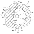
- FIG. 3 is a schematic view of the nozzle hole 33 as viewed from the inside of the nozzle body 20.
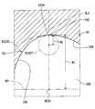
- FIG. 4 shows a cross section on the first virtual plane VP1 that is a plane including the injection hole axis HC33 of the injection nozzle 30 and is parallel to the central axis CA30.
- FIG. 4 shows the valve closing direction and the valve opening direction shown in FIG.
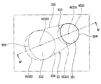
- FIG. 5 shows a cross section of the nozzle hole 33 on the second virtual plane VP2 perpendicular to the nozzle hole axis HC33.
- the other injection holes 31, 32, 34, 35, 36 of the fuel injection valve 1 have the same characteristics.
- the cross-sectional area of the inner opening 331 is smaller than the cross-sectional area of the outer opening 332.
- the inner opening 331 has a cross-sectional shape different from a perfect circle. Specifically, when compared with the virtual circle VC331 centered on the point HC331 on the nozzle hole axis HC33 as a reference, the edge 333 on one side of the edges forming the inner opening 331 is the edge on the other side. It is located closer to the point HC331 than the part 334.
- the outer opening 332 has a cross-sectional shape different from a perfect circle.
- the edge 338 on one side among the edges forming the outer opening 332 is the edge on the other side. It is located closer to the point HC332 than 339.
- the shape of the two openings of the injection hole 33 will be described in more detail based on the shape of the injection hole passage 330 that connects the inner opening 311 and the outer opening 312 with reference to FIGS.
- the nozzle hole passage 330 is formed of a first inner wall 335 and a second inner wall 336.
- the first inner wall 335 has a cross-sectional shape shown in FIG. 4 located on the valve closing direction side of the nozzle hole shaft HC33 shown in FIG.
- the second inner wall 336 is positioned on the valve opening direction side as the “opposite side to the valve closing direction side” of the nozzle hole shaft HC33 shown in FIG.
- FIG. 4 shows a virtual line VL336 that is at the same distance as the distance from the nozzle hole axis HC33 to the first inner wall 335 on the valve opening direction side of the nozzle hole axis HC33.
- the virtual line VL336 is also a line that connects the virtual circle VC331 and the virtual circle VC332 in FIG. 3 in the direction along the nozzle hole axis HC33.
- the first inner wall 335 is a circle of a virtual circle VC335 whose cross-sectional shape on the second virtual plane VP2, which is also the cross-sectional shape of the nozzle hole 33, is centered on a point on the nozzle hole axis HC33. It is formed in an arc shape. That is, the nozzle hole axis HC33 is also a line connecting the centers of virtual circles VC335 including the cross-sectional shape of the first inner wall 335 on the second virtual plane VP2 as a part of the circumference.
- the first inner wall 335 when the intersecting line between the first virtual plane VP1 and the first inner wall 335 is a first intersecting line CL33, the first inner wall 335 has a cross-sectional shape on the second virtual plane VP2 as shown in FIG. Are formed so as to form a central angle of 90 degrees in each of the two circumferential directions from the point on the first intersection line CL33 when viewed from the point on the nozzle hole axis HC33 (angles A11 and A12 shown in FIG. 5).
- the first inner wall 335 is formed so that the cross-sectional shape on the second virtual plane VP2 is plane symmetric with the first virtual plane VP1 as a symmetry plane.
- FIG. 5 shows a virtual line VL3 connecting the connection point P33 between the first inner wall 335 and the second inner wall 336 and a point on the nozzle hole axis HC33.
- the second inner wall 336 has a cross-sectional shape on the second virtual plane VP2 located closer to the injection hole axis HC33 than the cross-sectional shape of the first inner wall 335.
- the second inner wall 336 has a shape crushed toward the nozzle hole axis HC33 as compared with the cross-sectional shape of the first inner wall 335 on the second virtual plane VP2.
- the second inner wall 336 is formed such that the cross-sectional shape on the second virtual plane VP2 forms a central angle of 180 degrees when viewed from a point on the nozzle hole axis HC33 (the angle shown in FIG. 5). A13).
- the second inner wall 336 is formed so that the cross-sectional shape on the second virtual plane VP2 is plane-symmetric with the first virtual plane VP1 as a symmetry plane.
- the end E336 of the second inner wall 336 connected to the first inner wall 335 is formed so as to be smoothly connected to the first inner wall 335 as shown in FIG. Thereby, the inner wall which forms the nozzle hole channel
- the radius of the virtual circle VC337 including the cross-sectional shape of the end portion E336 of the second inner wall 336 as a part of the arc is the radius R2
- FIG. 7A shows a cross section that is a cross-sectional view of the nozzle hole 33 perpendicular to the nozzle axis HC33.
- FIG. 7B shows a cross-section that is a cross-sectional view perpendicular to the injection hole axis HC93 of the injection hole 93 of the fuel injection valve 9 as a comparative example.
- the cross-sectional shape of the injection hole 93 is formed in a perfect circle centered on a point on the injection hole axis HC93.
- the fuel injection valve 9 of the comparative example when the needle is separated from the valve seat, the fuel in the nozzle body flows into the injection hole 93.
- the fuel flowing into the nozzle hole 93 forms a liquid film LF9 on the inner wall of the nozzle hole forming the nozzle hole passage 930 of the nozzle hole 93.
- the inner wall of the nozzle hole on one side where the liquid film LF9 of the fuel that is relatively thick as viewed from the nozzle hole axis HC93 is formed is the nozzle hole inner wall 935, and opposite to the nozzle hole inner wall 935 across the nozzle hole axis HC93.
- the nozzle hole inner wall located on the side is referred to as a nozzle hole inner wall 936.
- the spread degree Dsp of the fuel liquid film LF9 has a relatively large value.
- the first inner wall 335 in which the liquid film LF3 of the fuel that is relatively thick as viewed from the nozzle hole axis HC33 is formed is formed in a circular arc having a perfect circular cross section.
- the two inner walls 336 are formed so that the cross-sectional shape is located closer to the nozzle hole axis HC33 than the cross-sectional shape of the first inner wall 335. Accordingly, as shown in FIG. 7A, the fuel liquid film LF ⁇ b> 3 formed on the first inner wall 335 is relatively difficult to move on the second inner wall 336.
- the sum of the lengths L361 and L362 of the fuel liquid film LF3 on the second inner wall 336 is shorter than that of the fuel injection valve 9 of the comparative example. That is, the spread degree Dsp of the fuel liquid film, which is the ratio of the lengths L361 and L362 of the fuel liquid film LF3 on the second inner wall 336 to the length L35 of the fuel liquid film LF3 on the first inner wall 335, is The value is smaller than that of the fuel injection valve 9.
- the spread of the fuel liquid film on the second inner wall 336 can be suppressed as compared with the nozzle hole having a perfect circular cross section.
- the fuel injection valve 1 can reduce the change in the spread range and spray shape of the fuel after injection depending on the spread degree of the liquid film of the fuel, and thus can improve the stability of the fuel spray characteristics.
- the first inner walls of the nozzle holes 31, 32, 33, 34, 35, 36 have cross-sectional shapes on the second imaginary plane, respectively. It is formed so as to form a central angle of 180 degrees when viewed from a point on HC34, HC35, and HC36.
- the cross-sectional shape of the second inner wall on the second virtual plane is formed in the nozzle hole passages 310, 320, 330, 340, 350, 360 as compared with the case where the central angle is 180 degrees or more when viewed from the nozzle hole axis.
- the liquid film of the fuel can be formed relatively wide. Therefore, the fuel injection valve 1 can make a lot of fuel into fine particles.
- the first inner walls of the nozzle holes 31, 32, 33, 34, 35, and 36 each have a sectional shape on the second imaginary plane having the nozzle hole axes HC31, HC32, HC33, HC34, It is formed in the shape of a perfect circular arc centering on a point on HC35 and HC36.
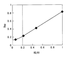
- the applicant of the present application conducted an experiment on the relationship between the shape of the end E336 of the second inner wall 336 and the fuel spread Dsp.
- the result is shown in FIG.
- the horizontal axis shows the ratio of the radius R2 of the virtual circle VC337 and the radius R1 of the virtual circle VC335, and the vertical axis shows the fuel spread Dsp.
- the fuel spread degree Dsp increases as the ratio of the radius R2 to the radius R1 increases.
- the fuel spread degree Dsp in the nozzle hole passage is 0.2. From the experimental results shown in FIG. 8, it is clear that the fuel spread degree Dsp can be set to 0.2 when the ratio of the radius R2 to the radius R1 is 0.2 or less.
- the nozzle holes 31, 32, 33, 34, 35, and 36 are formed so that the ratio of the radius R2 to the radius R1 is 0.2 or less.
- the liquid film of fuel formed in the nozzle hole passages 310, 320, 330, 340, 350, 360 is relatively difficult to spread along the second inner wall 336.
- the fuel injection valve 1 can further improve the stability of the fuel spray characteristics.
- the injection holes 31, 32, 33, 34, 35, and 36 are formed so that the first inner wall and the second inner wall are smoothly connected (see FIG. 6).
- path 310,320,330,340,350,360 will be formed from a curve. Therefore, the fuel injection valve 1 can prevent the occurrence of turbulent fuel flow at the corners.
- the nozzle holes 31, 32, 33, 34, 35, and 36 have a sectional shape on the second imaginary plane that includes the nozzle hole axes HC31, HC32, HC33, HC34, HC35, and HC36. It is formed so as to be plane-symmetric with a virtual plane as a plane of symmetry. Thereby, the liquid film of fuel can be expanded symmetrically with respect to the first virtual plane. Therefore, the fuel injection valve 1 can inject fuel evenly with respect to the direction of fuel injected from the injection holes 31, 32, 33, 34, 35, 36.
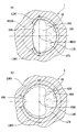
- FIG. 9 and 10 are sectional views of the injection nozzle 50 provided in the fuel injection valve 2 according to the second embodiment.
- shaft HC53 of the nozzle hole 53 which the injection nozzle 50 has is shown.
- the nozzle hole axis HC53 is a line connecting the centers of virtual circles VC335 including the cross-sectional shape of the first inner wall 335 on the second virtual plane as a part of the circumference.
- the other nozzle holes of the injection nozzle 50 have the same characteristics.
- the nozzle hole passage 530 of the nozzle hole 53 is formed of a first inner wall 335, a second inner wall 536, and a third inner wall 537.
- the second inner wall 536 is provided on the opposite side of the first inner wall 335 across the nozzle hole axis HC53. That is, the second inner wall 536 is a plane including the nozzle hole axis HC53, and the sectional shape on the first virtual plane VP1 parallel to the central axis CA30 is the valve opening direction side of the nozzle hole axis HC33 on the first virtual plane VP1. Is located.
- the third inner wall 537 is provided between the first inner wall 335 and the second inner wall 536. For convenience, FIG.
- FIG. 9 shows a virtual line VL31 connecting a connection point P531 between the first inner wall 335 and the third inner wall 337 and a point on the nozzle hole axis HC53. Further, an imaginary line VL32 connecting a connection point P532 between the second inner wall 336 and the third inner wall 337 and a point on the nozzle hole axis HC53 is shown.
- the second inner wall 536 has a cross-sectional shape shown in FIG. 9 positioned closer to the nozzle hole axis HC53 than the cross-sectional shape of the first inner wall 335.
- the second inner wall 536 is formed to have an arcuate shape of a virtual circle VC536 having a larger radius than the radius of the virtual circle VC335.
- the second inner wall 536 is formed such that the cross-sectional shape shown in FIG. 9 forms a central angle smaller than 180 degrees when viewed from a point on the nozzle hole axis HC53 (angle A23 shown in FIG. 9). .
- the third inner wall 537 is formed so as to smoothly connect the first inner wall 335 and the second inner wall 536, as shown in FIG. Thereby, the inner wall which forms the nozzle hole channel
- the radius of the virtual circle VC537 including the cross-sectional shape of the third inner wall 537 as a part of the arc is a radius R3, the third inner wall 537 is formed so that R3 / R1 is 0.2 or less. Yes.
- a tangent line that contacts the cross-sectional shape of the first inner wall 335 at the connection point P531 is a first tangent line L531
- a tangent line that contacts the cross-sectional shape of the second inner wall 536 at the connection point P532 is a second tangent line L532.
- the nozzle hole inner wall of the nozzle hole 53 is formed such that an angle A24 formed by the first tangent L531 and the second tangent L532 is 40 degrees or more.
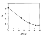
- the applicant of the present application conducted an experiment on the relationship between the angle A24 and the fuel spread Dsp.
- the result is shown in FIG.
- the horizontal axis indicates the angle A24 formed by the first tangent L531 and the second tangent L532, and the vertical axis indicates the fuel spread Dsp.
- the fuel spread degree Dsp decreases as the angle A24 increases.
- it is desirable that the angle A24 is 0.2 or less.
- the second inner wall 536 is formed so as to be positioned closer to the nozzle hole axis HC53 than the first inner wall 335 on which a relatively thick fuel liquid film is formed.
- the fuel injection valve 2 has the same effect as 1st embodiment.
- the injection hole 53 has an injection hole inner wall so that an angle A24 formed by the first tangent L531 and the second tangent L532 is 40 degrees or more.
- the spread degree Dsp of the fuel becomes 0.2 or less, and the fuel is difficult to spread on the second inner wall 536. Therefore, the fuel injection valve 2 can further improve the stability of the fuel spray characteristics.
- FIG. 12 shows a cross-sectional view of the injection nozzle 60 provided in the fuel injection valve 3 according to the third embodiment.
- shaft HC63 of the nozzle hole 63 which the injection nozzle 60 has is shown.
- the nozzle hole axis HC63 is a line connecting the centers of virtual circles VC335 including the cross-sectional shape of the first inner wall 335 on the second virtual plane as a part of the circumference.
- the other nozzle holes of the injection nozzle 60 have the same characteristics.
- the nozzle hole passage 630 of the nozzle hole 63 is formed by the first inner wall 335 and the second inner wall 636.
- the second inner wall 636 is provided on the side opposite to the first inner wall 335 across the nozzle hole axis HC63. That is, the second inner wall 636 is a plane including the nozzle hole axis HC63, and the sectional shape on the first virtual plane VP1 parallel to the central axis CA30 is the valve opening direction side of the nozzle hole axis HC63 on the first virtual plane VP1. Is located.
- the second inner wall 636 is provided at a position where the cross-sectional shape shown in FIG. 12 is closer to the nozzle hole axis HC63 than the cross-sectional shape of the first inner wall 335.
- a virtual line connecting a connection point P63 between the first inner wall 335 and the second inner wall 636 and a point on the nozzle hole axis HC63 is defined as a virtual line VLL3.
- the line is assumed to be a virtual line VLS3.
- the cross-sectional shape of the second inner wall 636 on the second virtual plane is formed in an arc shape of a virtual ellipse VC636 having the virtual line VLL3 as the major axis and the virtual line VLS3 as the minor axis.
- the length RL of the virtual line VLL3 is the same length as the radius of the virtual circle VC335, and the ratio of the length RS of the virtual line VLS3 to the length RL of the virtual line VLL3 is 0.5 or less. .
- the second inner wall 636 is formed so that the cross-sectional shape on the second imaginary plane forms a central angle of 180 degrees when viewed from a point on the nozzle hole axis HC63 (angle A33 shown in FIG. 12). Thereby, the second inner wall 636 is formed so that the cross-sectional shape on the second virtual plane is plane-symmetric with the first virtual plane VP1 as the symmetry plane.
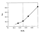
- FIG. 13 shows the ratio of the length RS of the virtual line VLS3 to the length RL of the virtual line VLL3, and the fuel spread degree Dsp is shown on the vertical axis.
- the fuel spread degree Dsp increases as the ratio of the length RS to the length RL increases. Therefore, in order to set the fuel spread degree Dsp to 0.2, which is a guideline that the influence of the shape change of the nozzle hole becomes relatively small, the ratio of the length RS to the length RL is set to 0.5 or less. It is desirable.
- the second inner wall 636 is provided closer to the nozzle hole axis HC63 than the first inner wall 335 on which a relatively thick liquid film of fuel is formed.
- the fuel injection valve 3 has the same effect as 1st embodiment.
- the injection hole 63 is configured such that the ratio of the length of the major axis to the minor axis of the elliptical shape that is the cross-sectional shape of the second inner wall 636 on the second virtual plane is 0.5 or less. Is formed. Thereby, the spread degree Dsp of the fuel becomes 0.2 or less, and the fuel hardly spreads on the second inner wall 636. Therefore, the fuel injection valve 3 can further improve the stability of the fuel spray characteristics.
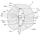
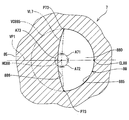
- FIG. 14 shows a cross-sectional view of the injection nozzle 70 provided in the fuel injection valve 4 according to the fourth embodiment.
- shaft HC73 of the nozzle hole 73 which the injection nozzle 70 has is shown.
- the injection hole 73 will be described, but the other injection holes of the injection nozzle 70 have the same characteristics.
- the nozzle hole passage 730 of the nozzle hole 73 is formed by the first inner wall 735 and the second inner wall 736.
- the first inner wall 735 is a plane including the nozzle hole axis HC73, and the cross-sectional shape on the first virtual plane VP1 parallel to the central axis CA30 is located on the valve closing direction side of the nozzle hole axis HC33 on the first virtual plane VP1. is doing.
- the second inner wall 336 has a cross-sectional shape on the first virtual plane VP1 positioned on the valve opening direction side of the nozzle hole axis HC33 on the first virtual plane VP1.
- the first inner wall 735 is formed in an arcuate shape of a virtual ellipse VC735 having a cross-sectional shape shown in FIG. That is, the nozzle hole axis HC73 is also a line connecting the centers of the virtual ellipses VC735 including the cross-sectional shape of the first inner wall 735 on the second virtual plane as a part of the circumference.
- the intersecting line between the first virtual plane VP1 and the first inner wall 735 is a first intersecting line CL73
- the first inner wall 735 has a cross-sectional shape shown in FIG.
- first inner wall 735 is formed so that the cross-sectional shape shown in FIG. 14 is plane-symmetric with the first virtual plane VP1 as the plane of symmetry.
- the second inner wall 736 has a cross-sectional shape shown in FIG. 14 located closer to the nozzle hole axis HC73 than the cross-sectional shape of the first inner wall 735.
- a virtual line connecting a connection point P73 between the first inner wall 735 and the second inner wall 736 and a point on the nozzle hole axis HC73 is defined as a virtual line VLL4.
- a virtual line that intersects the virtual line VLL4 perpendicularly and extends in the direction of the second inner wall 736 and that connects the point P736 on the second inner wall 736 and the point on the nozzle hole axis HC73 is virtual. Line VLS4.
- the cross-sectional shape of the second inner wall 736 on the second virtual plane is formed in an arc shape of a virtual ellipse VC736 having the virtual line VLL4 as the major axis and the virtual line VLS4 as the minor axis.
- the length RL of the virtual line VLL3 is the same length as the major axis of the virtual ellipse VC735.
- the length RS of the virtual line VLS4 is 0.5 times or less of the length RL.
- the second inner wall 736 is formed such that the cross-sectional shape on the second imaginary plane forms a central angle of 180 degrees when viewed from a point on the nozzle hole axis HC73 (angle A43 shown in FIG. 14). ).
- the second inner wall 736 is formed so that the cross-sectional shape on the second virtual plane is plane symmetric with the first virtual plane as a symmetry plane.
- the second inner wall 736 is provided closer to the nozzle hole axis HC73 than the first inner wall 735 on which a relatively thick fuel liquid film is formed.
- the fuel injection valve 4 has the same effect as 1st embodiment.
- the injection hole 73 is configured such that the ratio of the length between the major axis and the minor axis of the elliptical shape that is the cross-sectional shape of the second inner wall 736 on the second virtual plane is 0.5 or less. Is formed. Thereby, the fuel injection valve 4 can further reduce the temporal change of the fuel spray characteristics.
- the fifth embodiment is different from the first embodiment in that the first inner wall has a protruding portion.
- symbol is attached
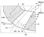
- FIG. 15 is a cross-sectional view of the injection nozzle 75 provided in the fuel injection valve 5 according to the fifth embodiment.
- shaft HC78 of the nozzle hole 78 which the injection nozzle 75 has is shown.
- the injection hole 78 will be described, but the other injection holes of the injection nozzle 70 have the same characteristics.
- the nozzle hole passage 780 of the nozzle hole 78 is formed by the first inner wall 785 and the second inner wall 336.
- the first inner wall 785 is a plane including the nozzle hole axis HC78, and the cross-sectional shape on the first virtual plane VP1 parallel to the central axis CA30 is located on the valve closing direction side of the nozzle hole axis HC78 on the first virtual plane VP1. is doing.
- a part of the first inner wall 785 is formed in an arc shape of a virtual ellipse VC785 centering on a point on the nozzle hole axis HC78 in the sectional shape shown in FIG. That is, the nozzle hole axis HC787 is also a line connecting the centers of the virtual ellipses VC785 including the cross-sectional shape of the first inner wall 785 on the second virtual plane as a part of the circumference.
- the first inner wall 785 has a protruding portion 788 that protrudes toward the nozzle hole axis HC78. In the cross-sectional shape shown in FIG.
- the point on the first intersection line CL78 is Of the inner wall surface 789 of the projecting portion 788, it is located closest to the nozzle hole axis HC78.
- the inner wall surface 789 of the protrusion 788 is smoothly connected from the position of the first intersection line CL78 to the arc shape of the virtual ellipse VC785. Thereby, the cross-sectional shape of the injection hole 78 is formed in a substantially M shape.
- the first inner wall 785 has a central angle of 90 degrees in each of the two circumferential directions from the point on the first intersection line CL78 when the cross-sectional shape shown in FIG. (Angles A51 and A52 shown in FIG. 15). That is, the first inner wall 785 is formed so that the cross-sectional shape shown in FIG. 15 is plane-symmetric with the first virtual plane VP1 as the plane of symmetry.
- FIG. 15 shows a virtual line VL5 that connects a connection point P53 between the first inner wall 785 and the second inner wall 336 and a point on the nozzle hole axis HC78.
- An end portion of the second inner wall 336 that connects to the first inner wall 785 is formed to smoothly connect to the first inner wall 785.
- path 780 will be formed from a curved surface.
- FIG. 16 shows a cross-section that is a cross-sectional view perpendicular to the injection hole axis HC78 of the injection hole 78 of the fuel injection valve 5.
- the fuel in the nozzle body 20 flows into the injection hole 78.
- the fuel flowing into the nozzle hole 78 forms a relatively thick fuel film LF7 on the first inner wall 785.
- the fuel liquid film formed on the projecting portion 788 moves in the circumferential direction of the nozzle hole passage 780 using the inclination of the inner wall surface 789 of the projecting portion 788.
- the fuel injection valve 5 can achieve the effects (1), (2), (4) to (6) of the first embodiment, and can further atomize the fuel.
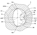
- FIG. 17 shows a cross-sectional view of the injection nozzle 80 provided in the fuel injection valve 6 according to the sixth embodiment.
- shaft HC83 of the nozzle hole 83 which the injection nozzle 80 has is shown.
- the injection hole 83 will be described, but the other injection holes of the injection nozzle 80 have the same characteristics.
- the nozzle hole passage 830 of the nozzle hole 83 is formed by the first inner wall 835 and the second inner wall 836.
- the first inner wall 835 is a plane including the nozzle hole axis HC83, and the cross-sectional shape on the first virtual plane VP1 parallel to the central axis CA30 is located on the valve closing direction side of the nozzle hole axis HC83 on the first virtual plane VP1. is doing.
- the second inner wall 836 has a cross-sectional shape on the first virtual plane VP1 positioned on the valve opening direction side of the nozzle hole axis HC83 on the first virtual plane VP1.
- the first inner wall 835 is formed in a circular arc shape of a virtual circle VC835 centering on a point on the nozzle hole axis HC83 in the sectional shape shown in FIG. That is, the nozzle hole axis HC83 is also a line connecting the centers of virtual circles VC835 including the cross-sectional shape of the first inner wall 835 on the second virtual plane as a part of the circumference.
- the first inner wall 835 when the intersection line between the first virtual plane VP1 and the first inner wall 835 is a first intersection line CL83, the first inner wall 835 has a cross-sectional shape on the second virtual plane perpendicular to the nozzle hole axis HC83.
- the central angle of 90 degrees or more is formed in each of the two circumferential directions from the point on the first intersection line CL83 (angles A61 and A62 shown in FIG. 17). That is, the first inner wall 835 is formed so that the cross-sectional shape shown in FIG. 17 is plane-symmetric with the first virtual plane VP1 as the plane of symmetry.
- FIG. 17 shows a virtual line VL6 that connects a connection point P63 between the first inner wall 835 and the second inner wall 836 and a point on the nozzle hole axis HC83.
- the second inner wall 836 has a cross-sectional shape shown in FIG. 17 located closer to the nozzle hole axis HC33 than the cross-sectional shape of the first inner wall 835.
- the second inner wall 836 is formed such that the cross-sectional shape shown in FIG. 17 forms a central angle smaller than 180 degrees when viewed from the point on the nozzle hole axis HC83 (angle A63 shown in FIG. 17).
- An end portion of the second inner wall 836 that is connected to the first inner wall 835 is formed so as to be smoothly connected to the first inner wall 835. Thereby, the inner wall which forms the nozzle hole channel
- the second inner wall 836 located closer to the injection hole axis HC83 than the cross-sectional shape of the first inner wall 835 has a central angle smaller than 180 degrees in cross-sectional shape when viewed from a point on the injection hole axis HC83. It is formed to make. Thereby, the fuel injection valve 6 has the effects (1), (3), and (5) of the first embodiment.
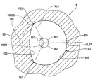
- FIG. 18 is a cross-sectional view of the injection nozzle 85 provided in the fuel injection valve 7 according to the seventh embodiment.
- shaft HC88 of the nozzle hole 88 which the injection nozzle 85 has is shown.
- the injection hole 88 will be described, but the other injection holes of the injection nozzle 85 have the same characteristics.
- the nozzle hole passage 880 of the nozzle hole 88 is formed by the first inner wall 885 and the second inner wall 886.
- the first inner wall 885 is a plane including the nozzle hole axis HC88, and the cross-sectional shape on the first virtual plane VP1 parallel to the central axis CA30 is located on the valve closing direction side of the nozzle hole axis HC88 on the first virtual plane VP1. is doing.
- the second inner wall 886 has a cross-sectional shape on the first virtual plane VP1 located on the valve opening direction side of the nozzle hole axis HC88 on the first virtual plane VP1.
- the first inner wall 885 is formed in an arcuate shape of a virtual circle VC885 having a cross-sectional shape shown in FIG. 18 which is also a cross-sectional shape of the nozzle hole 88 centered on a point on the nozzle hole axis HC88. That is, the nozzle hole axis HC88 is also a line connecting the centers of virtual circles VC885 that include the cross-sectional shape of the first inner wall 885 on the second virtual plane as a part of the circumference.
- the first inner wall 885 when the intersecting line between the first virtual plane VP1 and the first inner wall 885 is a first intersecting line CL88, the first inner wall 885 has a cross-sectional shape on the second virtual plane perpendicular to the nozzle hole axis HC88. As seen from the point on the nozzle hole axis HC88, the center angle is formed to be smaller than 90 degrees in each of the two circumferential directions from the point on the first intersection line CL88 (angles A71 and A72 shown in FIG. 18). That is, the first inner wall 885 is formed so that the cross-sectional shape shown in FIG. 18 is plane-symmetric with the first virtual plane VP1 as the plane of symmetry. For convenience, FIG. 18 shows a virtual line VL7 that connects a connection point P73 between the first inner wall 885 and the second inner wall 886 and a point on the nozzle hole axis HC88.
- the second inner wall 886 is provided at a position where the cross-sectional shape shown in FIG. 18 is closer to the nozzle hole axis HC88 than the cross-sectional shape of the first inner wall 885.
- the second inner wall 886 is formed such that the cross-sectional shape shown in FIG. 18 forms a central angle larger than 180 degrees when viewed from a point on the nozzle hole axis HC88 (angle A73 shown in FIG. 17).
- An end portion of the second inner wall 886 that connects to the first inner wall 885 is formed to smoothly connect to the first inner wall 885. Thereby, the inner wall which forms the nozzle hole channel
- the second inner wall 886 located closer to the injection hole axis HC88 than the cross-sectional shape of the first inner wall 885 has a central angle greater than 180 degrees when the cross-sectional shape is viewed from a point on the injection hole axis HC88. It is formed to make. Thereby, the fuel injection valve 7 has the effects (1), (3), and (5) of the first embodiment.
- the first inner wall has a cross-sectional shape on the second imaginary plane that forms the same central angle in each of the two circumferential directions from the point on the first intersection line when viewed from the point on the nozzle hole axis. It has been formed.
- the central angles need not be the same.
- the second inner wall is formed such that a cross-sectional shape on the second imaginary plane that intersects perpendicularly with the nozzle hole axis forms a central angle of 180 degrees when viewed from a point on the nozzle hole axis. He said.
- the central angle of the second inner wall is not limited to this. The angle may be smaller than 180 degrees as in the sixth embodiment, or may be larger than 180 degrees as in the seventh embodiment.
- the second inner wall may be formed in an arc shape of a virtual circle or a virtual ellipse.
- the third inner wall be provided between the first inner wall and the second inner wall.
- the second inner wall has the cross-sectional shape of the end connected to the first inner wall of the second inner wall with respect to the radius of the virtual circle including the cross-sectional shape of the first inner wall as a part of the arc as a part of the arc.
- the radius of the included virtual circle is assumed to be 0.2 or less.
- the radius of the virtual circle including the cross-sectional shape of the third inner wall as a part of the arc with respect to the radius of the virtual circle including the cross-sectional shape of the first inner wall as a part of the arc is 0. .2 or less.
- the relationship between these radii is not limited to this.
- the angle formed by the first tangent and the second tangent is 40 degrees or less.
- the angle formed by the first tangent and the second tangent is not limited to this. Further, the relationship in which the angle formed by the first tangent and the second tangent is 40 degrees or less may also be applied to the first, third to seventh embodiments.
- the relationship between the length of the major axis and the minor axis of the virtual ellipse whose cross-sectional shape of the second inner wall is a part of the arc is 0.5 times the length of the minor axis with respect to the major axis. It was assumed that However, the length relationship between the major axis and the minor axis of the virtual ellipse is not limited to this.
- the first inner wall may have a protrusion as in the fifth embodiment.
- the cross-sectional shapes of the first inner wall and the second inner wall on the second virtual plane are plane symmetric with the first virtual plane as a plane of symmetry. However, it may not be plane symmetric.
- nozzle holes there are six nozzle holes.
- the number of nozzle holes is not limited to this.
- the present disclosure is a fuel injection valve that includes a nozzle body, a needle, and a drive unit.
- the nozzle body has an injection hole capable of injecting fuel and a valve seat formed around the inner opening of the injection hole.
- the needle is provided so as to be able to contact the valve seat. When the needle is in contact with the valve seat, the flow of fuel between the nozzle body and the outside through the nozzle hole is restricted, and when separated from the valve seat, the fuel flow between the nozzle body and the outside through the nozzle hole is allowed.
- the drive unit can reciprocate the needle.
- the injection hole is formed such that the cross-sectional area of the inner opening is smaller than the cross-sectional area of the outer opening of the injection hole.
- the nozzle hole passage that connects the inner opening and the outer opening is the nozzle hole.
- the fuel injection valve of the present disclosure when the fuel in the nozzle body enters the nozzle hole passage through the inner opening, the fuel mainly flows toward the outer opening along the first inner wall. At this time, since the liquid film of fuel flowing along the first inner wall spreads in the circumferential direction of the nozzle hole passage, it flows along the second inner wall.
- the second inner wall is located closer to the nozzle hole shaft than the first inner wall, so that a liquid film of fuel that is going to spread from the first inner wall to the second inner wall is formed on the second inner wall. It becomes difficult to spread, and the spread of the fuel liquid film is suppressed.
- the fuel injection valve according to the present disclosure can reduce the change of the fuel spread range and the spray shape in the combustion chamber depending on the extent of the fuel liquid film spread, thereby improving the stability of the fuel spray characteristics. Can do.
Landscapes
- Engineering & Computer Science (AREA)
- Chemical & Material Sciences (AREA)
- Combustion & Propulsion (AREA)
- Mechanical Engineering (AREA)
- General Engineering & Computer Science (AREA)
- Physics & Mathematics (AREA)
- Electromagnetism (AREA)
- Fuel-Injection Apparatus (AREA)
Priority Applications (1)
| Application Number | Priority Date | Filing Date | Title |
|---|---|---|---|
| US16/071,181 US10865753B2 (en) | 2016-02-15 | 2017-01-13 | Fuel injection valve |
Applications Claiming Priority (2)
| Application Number | Priority Date | Filing Date | Title |
|---|---|---|---|
| JP2016-025800 | 2016-02-15 | ||
| JP2016025800A JP6463286B2 (ja) | 2016-02-15 | 2016-02-15 | 燃料噴射弁 |
Publications (1)
| Publication Number | Publication Date |
|---|---|
| WO2017141592A1 true WO2017141592A1 (ja) | 2017-08-24 |
Family
ID=59624953
Family Applications (1)
| Application Number | Title | Priority Date | Filing Date |
|---|---|---|---|
| PCT/JP2017/000938 Ceased WO2017141592A1 (ja) | 2016-02-15 | 2017-01-13 | 燃料噴射弁 |
Country Status (3)
| Country | Link |
|---|---|
| US (1) | US10865753B2 (enExample) |
| JP (1) | JP6463286B2 (enExample) |
| WO (1) | WO2017141592A1 (enExample) |
Families Citing this family (5)
| Publication number | Priority date | Publication date | Assignee | Title |
|---|---|---|---|---|
| US11098686B2 (en) * | 2017-05-12 | 2021-08-24 | Hitachi Automotive Systems, Ltd. | Fuel injection valve |
| JP2020008013A (ja) * | 2018-07-12 | 2020-01-16 | 株式会社Soken | 燃料噴射弁 |
| US10808668B2 (en) * | 2018-10-02 | 2020-10-20 | Ford Global Technologies, Llc | Methods and systems for a fuel injector |
| EP3845756A4 (en) * | 2018-10-26 | 2022-08-10 | Hitachi Astemo, Ltd. | FUEL INJECTION VALVE |
| JP7439399B2 (ja) * | 2019-06-20 | 2024-02-28 | 株式会社デンソー | 燃料噴射弁 |
Citations (4)
| Publication number | Priority date | Publication date | Assignee | Title |
|---|---|---|---|---|
| JPS56106062A (en) * | 1980-01-26 | 1981-08-24 | Hino Motors Ltd | Hole nozzle |
| JP2006057462A (ja) * | 2004-08-17 | 2006-03-02 | Denso Corp | 噴孔部材、燃料噴射弁、および噴孔部材の製造方法 |
| JP2010216412A (ja) * | 2009-03-18 | 2010-09-30 | Hitachi Automotive Systems Ltd | 燃料噴射弁 |
| JP2015094234A (ja) * | 2013-11-08 | 2015-05-18 | 株式会社デンソー | 燃料噴射弁 |
Family Cites Families (2)
| Publication number | Priority date | Publication date | Assignee | Title |
|---|---|---|---|---|
| JP4196194B2 (ja) * | 2003-10-01 | 2008-12-17 | 株式会社デンソー | 噴孔部材およびそれを用いた燃料噴射弁 |
| JP5605325B2 (ja) | 2011-07-19 | 2014-10-15 | トヨタ自動車株式会社 | 燃料噴射弁 |
-
2016
- 2016-02-15 JP JP2016025800A patent/JP6463286B2/ja active Active
-
2017
- 2017-01-13 US US16/071,181 patent/US10865753B2/en active Active
- 2017-01-13 WO PCT/JP2017/000938 patent/WO2017141592A1/ja not_active Ceased
Patent Citations (4)
| Publication number | Priority date | Publication date | Assignee | Title |
|---|---|---|---|---|
| JPS56106062A (en) * | 1980-01-26 | 1981-08-24 | Hino Motors Ltd | Hole nozzle |
| JP2006057462A (ja) * | 2004-08-17 | 2006-03-02 | Denso Corp | 噴孔部材、燃料噴射弁、および噴孔部材の製造方法 |
| JP2010216412A (ja) * | 2009-03-18 | 2010-09-30 | Hitachi Automotive Systems Ltd | 燃料噴射弁 |
| JP2015094234A (ja) * | 2013-11-08 | 2015-05-18 | 株式会社デンソー | 燃料噴射弁 |
Also Published As
| Publication number | Publication date |
|---|---|
| US20190093617A1 (en) | 2019-03-28 |
| US10865753B2 (en) | 2020-12-15 |
| JP2017145697A (ja) | 2017-08-24 |
| JP6463286B2 (ja) | 2019-01-30 |
Similar Documents
| Publication | Publication Date | Title |
|---|---|---|
| JP6463286B2 (ja) | 燃料噴射弁 | |
| JP5537512B2 (ja) | 燃料噴射弁 | |
| US10208711B2 (en) | Gas injector including an outwardly opening valve closure element | |
| JP2016098702A (ja) | 燃料噴射弁 | |
| CN104033305B (zh) | 燃料喷射阀 | |
| JP6365450B2 (ja) | 燃料噴射装置 | |
| US20140251262A1 (en) | Fuel Injection Valve | |
| JP6471618B2 (ja) | 燃料噴射装置 | |
| US20140251264A1 (en) | Fuel Injection Valve | |
| JP5887291B2 (ja) | 燃料噴射弁 | |
| CN112368475B (zh) | 燃料喷射阀 | |
| JP6121870B2 (ja) | 燃料噴射装置の微粒化技術 | |
| JP6523984B2 (ja) | 燃料噴射弁 | |
| US10876508B2 (en) | Fuel injection valve | |
| JP2010216412A (ja) | 燃料噴射弁 | |
| JPWO2018198309A1 (ja) | 燃料噴射弁 | |
| WO2017145639A1 (ja) | 燃料噴射装置 | |
| JP2014025365A (ja) | 燃料噴射弁 | |
| US20200032755A1 (en) | Fuel injection device | |
| JP6468109B2 (ja) | 燃料噴射弁 | |
| WO2016163086A1 (ja) | 燃料噴射装置 | |
| JP6416564B2 (ja) | 燃料噴射弁 | |
| JP2017020394A (ja) | 燃料噴射装置 | |
| JP2019112984A (ja) | 燃料噴射弁 | |
| JP2003139017A (ja) | 燃料噴射装置 |
Legal Events
| Date | Code | Title | Description |
|---|---|---|---|
| 121 | Ep: the epo has been informed by wipo that ep was designated in this application |
Ref document number: 17752856 Country of ref document: EP Kind code of ref document: A1 |
|
| NENP | Non-entry into the national phase |
Ref country code: DE |
|
| 122 | Ep: pct application non-entry in european phase |
Ref document number: 17752856 Country of ref document: EP Kind code of ref document: A1 |