WO2017141563A1 - ダンパ及びこのダンパを備えた転倒防止装置 - Google Patents
ダンパ及びこのダンパを備えた転倒防止装置 Download PDFInfo
- Publication number
- WO2017141563A1 WO2017141563A1 PCT/JP2017/000241 JP2017000241W WO2017141563A1 WO 2017141563 A1 WO2017141563 A1 WO 2017141563A1 JP 2017000241 W JP2017000241 W JP 2017000241W WO 2017141563 A1 WO2017141563 A1 WO 2017141563A1
- Authority
- WO
- WIPO (PCT)
- Prior art keywords
- rod
- cylinder
- piston
- damper
- furniture
- Prior art date
- Legal status (The legal status is an assumption and is not a legal conclusion. Google has not performed a legal analysis and makes no representation as to the accuracy of the status listed.)
- Ceased
Links
Images





Classifications
-
- F—MECHANICAL ENGINEERING; LIGHTING; HEATING; WEAPONS; BLASTING
- F16—ENGINEERING ELEMENTS AND UNITS; GENERAL MEASURES FOR PRODUCING AND MAINTAINING EFFECTIVE FUNCTIONING OF MACHINES OR INSTALLATIONS; THERMAL INSULATION IN GENERAL
- F16F—SPRINGS; SHOCK-ABSORBERS; MEANS FOR DAMPING VIBRATION
- F16F9/00—Springs, vibration-dampers, shock-absorbers, or similarly-constructed movement-dampers using a fluid or the equivalent as damping medium
- F16F9/06—Springs, vibration-dampers, shock-absorbers, or similarly-constructed movement-dampers using a fluid or the equivalent as damping medium using both gas and liquid
- F16F9/08—Springs, vibration-dampers, shock-absorbers, or similarly-constructed movement-dampers using a fluid or the equivalent as damping medium using both gas and liquid where gas is in a chamber with a flexible wall
- F16F9/088—Springs, vibration-dampers, shock-absorbers, or similarly-constructed movement-dampers using a fluid or the equivalent as damping medium using both gas and liquid where gas is in a chamber with a flexible wall comprising a gas spring with a flexible wall provided within the cylinder on the piston rod of a monotubular damper or within the inner tube of a bitubular damper
-
- A—HUMAN NECESSITIES
- A47—FURNITURE; DOMESTIC ARTICLES OR APPLIANCES; COFFEE MILLS; SPICE MILLS; SUCTION CLEANERS IN GENERAL
- A47B—TABLES; DESKS; OFFICE FURNITURE; CABINETS; DRAWERS; GENERAL DETAILS OF FURNITURE
- A47B95/00—Fittings for furniture
- A47B95/002—Plinths, e.g. between furniture and ceiling or wall
-
- A—HUMAN NECESSITIES
- A47—FURNITURE; DOMESTIC ARTICLES OR APPLIANCES; COFFEE MILLS; SPICE MILLS; SUCTION CLEANERS IN GENERAL
- A47B—TABLES; DESKS; OFFICE FURNITURE; CABINETS; DRAWERS; GENERAL DETAILS OF FURNITURE
- A47B95/00—Fittings for furniture
- A47B95/008—Suspension fittings for cabinets to be hung on walls
-
- A—HUMAN NECESSITIES
- A47—FURNITURE; DOMESTIC ARTICLES OR APPLIANCES; COFFEE MILLS; SPICE MILLS; SUCTION CLEANERS IN GENERAL
- A47B—TABLES; DESKS; OFFICE FURNITURE; CABINETS; DRAWERS; GENERAL DETAILS OF FURNITURE
- A47B96/00—Details of cabinets, racks or shelf units not covered by a single one of groups A47B43/00 - A47B95/00; General details of furniture
- A47B96/14—Bars, uprights, struts, or like supports, for cabinets, brackets, or the like
-
- A—HUMAN NECESSITIES
- A47—FURNITURE; DOMESTIC ARTICLES OR APPLIANCES; COFFEE MILLS; SPICE MILLS; SUCTION CLEANERS IN GENERAL
- A47B—TABLES; DESKS; OFFICE FURNITURE; CABINETS; DRAWERS; GENERAL DETAILS OF FURNITURE
- A47B97/00—Furniture or accessories for furniture, not provided for in other groups of this subclass
-
- F—MECHANICAL ENGINEERING; LIGHTING; HEATING; WEAPONS; BLASTING
- F16—ENGINEERING ELEMENTS AND UNITS; GENERAL MEASURES FOR PRODUCING AND MAINTAINING EFFECTIVE FUNCTIONING OF MACHINES OR INSTALLATIONS; THERMAL INSULATION IN GENERAL
- F16F—SPRINGS; SHOCK-ABSORBERS; MEANS FOR DAMPING VIBRATION
- F16F15/00—Suppression of vibrations in systems; Means or arrangements for avoiding or reducing out-of-balance forces, e.g. due to motion
- F16F15/02—Suppression of vibrations of non-rotating, e.g. reciprocating systems; Suppression of vibrations of rotating systems by use of members not moving with the rotating systems
- F16F15/023—Suppression of vibrations of non-rotating, e.g. reciprocating systems; Suppression of vibrations of rotating systems by use of members not moving with the rotating systems using fluid means
-
- F—MECHANICAL ENGINEERING; LIGHTING; HEATING; WEAPONS; BLASTING
- F16—ENGINEERING ELEMENTS AND UNITS; GENERAL MEASURES FOR PRODUCING AND MAINTAINING EFFECTIVE FUNCTIONING OF MACHINES OR INSTALLATIONS; THERMAL INSULATION IN GENERAL
- F16F—SPRINGS; SHOCK-ABSORBERS; MEANS FOR DAMPING VIBRATION
- F16F9/00—Springs, vibration-dampers, shock-absorbers, or similarly-constructed movement-dampers using a fluid or the equivalent as damping medium
- F16F9/06—Springs, vibration-dampers, shock-absorbers, or similarly-constructed movement-dampers using a fluid or the equivalent as damping medium using both gas and liquid
-
- F—MECHANICAL ENGINEERING; LIGHTING; HEATING; WEAPONS; BLASTING
- F16—ENGINEERING ELEMENTS AND UNITS; GENERAL MEASURES FOR PRODUCING AND MAINTAINING EFFECTIVE FUNCTIONING OF MACHINES OR INSTALLATIONS; THERMAL INSULATION IN GENERAL
- F16F—SPRINGS; SHOCK-ABSORBERS; MEANS FOR DAMPING VIBRATION
- F16F9/00—Springs, vibration-dampers, shock-absorbers, or similarly-constructed movement-dampers using a fluid or the equivalent as damping medium
- F16F9/06—Springs, vibration-dampers, shock-absorbers, or similarly-constructed movement-dampers using a fluid or the equivalent as damping medium using both gas and liquid
- F16F9/066—Units characterised by the partition, baffle or like element
- F16F9/067—Partitions of the piston type, e.g. sliding pistons
-
- F—MECHANICAL ENGINEERING; LIGHTING; HEATING; WEAPONS; BLASTING
- F16—ENGINEERING ELEMENTS AND UNITS; GENERAL MEASURES FOR PRODUCING AND MAINTAINING EFFECTIVE FUNCTIONING OF MACHINES OR INSTALLATIONS; THERMAL INSULATION IN GENERAL
- F16F—SPRINGS; SHOCK-ABSORBERS; MEANS FOR DAMPING VIBRATION
- F16F9/00—Springs, vibration-dampers, shock-absorbers, or similarly-constructed movement-dampers using a fluid or the equivalent as damping medium
- F16F9/32—Details
- F16F9/50—Special means providing automatic damping adjustment, i.e. self-adjustment of damping by particular sliding movements of a valve element, other than flexions or displacement of valve discs; Special means providing self-adjustment of spring characteristics
- F16F9/512—Means responsive to load action, i.e. static load on the damper or dynamic fluid pressure changes in the damper, e.g. due to changes in velocity
- F16F9/5126—Piston, or piston-like valve elements
Definitions
- the present invention relates to a damper and a fall prevention device equipped with the damper.
- Patent Document 1 discloses a fall prevention device equipped with a conventional damper.
- the damper includes a cylinder, a rod guide, a piston, and a rod.
- the cylinder has a bottomed cylindrical shape.
- the rod guide seals the opening of the cylinder.
- the piston is slidably accommodated in the cylinder.
- the rod has a proximal end connected to the piston, slidably inserted through the rod guide, and a distal end protruding outside the cylinder.
- the damper also encloses hydraulic oil and compressed gas in the cylinder. This damper comprises the fall prevention apparatus attached between the upper surface of furniture, and a ceiling.
- This overturn prevention device is configured such that the bottom of the cylinder of the damper is positioned below the opening, the rod projects upward from the cylinder, and the center axis of the cylinder and the rod is inclined at a predetermined angle with respect to the horizontal plane. It is attached between the upper surface and the ceiling.
- this fall prevention device when the furniture is tilted due to shaking such as an earthquake, the damping force generated by the movement of the piston of the damper in the hydraulic oil acts on the furniture to suppress the tilt of the furniture, and the furniture falls Can be prevented.
- the piston of this damper can move not only in the hydraulic oil but also in the compressed gas sealed above the hydraulic oil.
- the damper cannot generate a damping force even if the piston moves in the compressed gas. That is, this damper cannot generate a damping force in the entire stroke range.
- the fall prevention device provided with this damper is arranged in a state where the piston is disposed in the compressed gas sealed above the hydraulic oil, and the upper surface and the ceiling of the furniture. There is a risk of being attached between.
- the anti-tip device is installed with the piston placed in compressed gas, when the furniture is tilted due to shaking such as an earthquake, the damper will contract until the piston moves into the hydraulic fluid. Does not occur. For this reason, this fall prevention device may cause the furniture to fall without the damping force of the damper acting effectively on the furniture.
- the present invention has been made in view of the above-described conventional situation, and provides a damper that exhibits a damping force in the entire stroke range, and by providing the damper, it is possible to satisfactorily prevent the article from overturning. Providing a fall prevention device that can be used is a problem to be solved.
- the damper of the present invention includes a cylinder, a rod guide, a piston, a rod, and a restricting portion.
- the cylinder has a bottomed cylindrical shape.
- the rod guide closes the opening of the cylinder.
- the piston is slidably accommodated in the cylinder.
- the rod has a base end connected to the piston, slidably inserted through the rod guide, and a distal end protruding outside the cylinder.
- the damper also encloses the working liquid and gas in the cylinder.
- the restricting portion is located below the gas, with the bottom of the cylinder positioned below the opening, the rod protruding upward from the cylinder, and the central axis of the cylinder and the rod inclined at a predetermined angle with respect to the horizontal plane.
- the position of the piston is regulated so that the piston is immersed in the sealed working liquid.
- the predetermined angle is assumed to be an angle at which the damper is actually used, and is, for example, 65 ° or more and 90 ° or less.
- the cylinder is partitioned by a piston into a rod side pressure chamber in which the base end portion of the rod is housed and an anti-rod side pressure chamber.
- the restricting portion may be disposed between the piston and the rod guide in the rod-side pressure chamber, and may have a predetermined length along the central axis of the rod.
- the restricting portion may be a bag body that is compressed and filled with gas and elastically deforms while maintaining the length of the rod in the central axis direction.
- the restricting portion may be a convex portion that protrudes inward from the inner surface of the cylinder on the rod guide side from the piston and that is engaged with the outer peripheral edge of the piston.
- the restricting portion may be an annular member fixed in the cylinder on the rod guide side relative to the piston and having an insertion hole through which the rod is inserted at the center.
- the restricting portion may protrude from the outer peripheral surface of the rod in the outward direction, and may be a hook portion that is engaged with the piston side surface of the rod guide.
- the fall prevention device of the present invention includes the damper.
- This damper is installed on the installation surface with the bottom of the cylinder positioned below the opening, the rod protruding upward from the cylinder, and the central axis of the cylinder and rod inclined at a predetermined angle with respect to the horizontal plane. It is attached between the upper surface of the mounted part and the ceiling.
- the predetermined angle is 65 ° to 85 °, which can prevent the article from falling down.
- articles may fall over due to earthquakes, such as furniture, beds with a plurality of beds connected vertically, a television (television), a refrigerator, a bookcase, a showcase, a server rack, etc. Some of them are included.
- Embodiments 1 to 5 embodying a fall prevention device including a damper according to the present invention will be described with reference to the drawings.
- the overturn prevention device of Embodiment 1 includes a damper 10 and a pair of base portions 30 ⁇ / b> A and 30 ⁇ / b> B. At least one or more fall prevention devices are attached between the upper surface of the furniture F and the ceiling C.
- the furniture F is installed on the floor surface with the back surface facing a wall surface W extending vertically from a floor surface (not shown).
- the furniture F has a rectangular parallelepiped shape, and has a door, a drawer, etc. (not shown) on the front (right side in FIG. 1), and can store clothes, accessories, and the like inside.
- the furniture F has a rectangular shape in which the horizontal cross-sectional shape is long in the left-right direction (the depth direction in FIG. 1).
- the furniture F may be tilted forward (rightward in FIG. 1) due to shaking such as an earthquake.
- the damper 10 includes a cylinder 11, a rod guide 12, a piston 13, a rod 14, a cylinder member 15 as a restricting portion, and two joint portions 16 provided at both ends. have.
- the cylinder 11 has a bottomed cylindrical shape.
- the rod guide 12 seals the opening of the cylinder 11.
- the piston 13 is slidably inserted into the cylinder 11.
- the rod 14 has a base end connected to the piston 13. Further, the rod 14 is inserted through the rod guide 12, and the tip side protrudes to the outside of the cylinder 11.
- the piston 13 partitions the inside of the cylinder 11 into a rod side pressure chamber 11B in which the base end portion of the rod 14 is housed and an anti-rod side pressure chamber 11A.
- the damper 10 encloses a predetermined amount of hydraulic oil Y and a predetermined amount of compressed gas G in the cylinder 11.
- the cylindrical member 15 that is a restricting portion has a substantially cylindrical shape.
- the cylindrical member 15 includes a cylindrical portion 15A, an abutting portion 15B provided at one end of the cylindrical portion 15A, and a connecting portion 15C provided at the other end of the cylindrical portion 15A.
- the inner diameter of the cylindrical portion 15 ⁇ / b> A is larger than the outer diameter of the rod 14.
- the contact portion 15B is formed such that one end portion of the cylindrical portion 15A is bent inward.
- the contact portion 15B has an annular shape in which an opening having an inner diameter slightly larger than the outer diameter of the rod 14 is formed at the center.
- the connecting portion 15C is formed such that the other end of the cylindrical portion 15A is bent outward.
- the connecting portion 15C includes an annular portion 15D having an outer diameter substantially equal to the inner diameter of the cylinder 11, and a cylindrical clamping portion 15E extending from the outer peripheral edge of the annular portion 15D in the direction opposite to the cylindrical portion 15A. ing.
- the cylindrical member 15 is fixed in the cylinder 11 with the sandwiching portion 15 ⁇ / b> E sandwiched between the inner peripheral surface of the cylinder 11 and the outer peripheral surface of the rod guide 12 with the rod 14 being inserted. That is, the cylinder member 15 that is a restricting portion is disposed in the rod-side pressure chamber 11B and between the piston 13 and the rod guide 12.
- the tipping prevention device provided with the damper 10 is such that the bottom of the cylinder 11 is positioned below the opening, the rod 14 projects upward from the cylinder 11, and the central axis of the cylinder 11 and the rod 14 is a horizontal plane. Is attached between the upper surface of the furniture F and the ceiling C in a state inclined at an angle between 65 ° and 75 °.
- the piston 13 is immersed in the hydraulic oil Y sealed below the compressed gas G in a state where the central axes of the cylinder 11 and the rod 14 are inclined at an angle between 65 ° and 75 ° with respect to the horizontal plane.
- the cylindrical member 15 has a predetermined length along the central axis of the rod 14 and regulates the position of the piston 13.
- the damper 10 when the piston 13 comes into contact with the contact portion 15B of the cylindrical member 15 interposed between the piston 13 and the rod guide 12, the piston 13 may move further to the rod guide 12 side. Can not. Further, the damper 10 is in a state where the piston 13 is immersed in the hydraulic oil Y while the piston 13 is in contact with the contact portion 15B of the cylindrical member 15. Therefore, the damper 10 can exert a damping force by moving the piston 13 in the hydraulic oil Y in the entire stroke range.
- This damper 10 is a pressure damper in which the damping force generated during the extension operation is smaller than the damping force generated during the contraction operation.
- the extension operation of the damper 10 means an operation in which the protruding length of the rod 14 from the cylinder 11 and the length of the damper 10 become longer.
- the contraction operation of the damper 10 means an operation in which the protruding length of the rod 14 from the cylinder 11 and the length of the damper 10 are shortened. Further, the expansion force of the compressed gas G sealed in the cylinder 11 acts on the damper 10 in the extending direction.
- the mechanism (mechanism) in which the damping force of the damper 10 is generated is a well-known structure, and will not be described.
- the cylinder 11 is partitioned by a piston 13 into a rod-side pressure chamber 11B in which the base end portion of the rod 14 is housed and an anti-rod-side pressure chamber 11A.
- the piston 13 is formed with an orifice for communicating between the two pressure chambers.
- the orifice functions as a damping force generating unit that applies a resistance to the flow of the hydraulic oil Y between the rod-side pressure chamber 11B and the anti-rod-side pressure chamber 11A accompanying the expansion / contraction operation of the damper 10 to generate a damping force.
- the piston 13 is formed with a communication passage that communicates between the pressure chambers via a check valve.
- the check valve allows the flow of the hydraulic oil Y from the rod-side pressure chamber 11B to the anti-rod-side pressure chamber 11A and blocks the reverse flow. For this reason, when the damper 10 is extended, the flow path of the hydraulic oil Y from the rod-side pressure chamber 11B to the anti-rod-side pressure chamber 11A becomes a path between the orifice and the communication path. On the other hand, when the damper 10 is contracted, the flow path of the hydraulic oil Y from the non-rod side pressure chamber 11A to the rod side pressure chamber 11B is only the orifice. For this reason, the damping force generated during the extension operation of the damper 10 is smaller than the damping force generated during the contraction operation.
- Each joint portion 16 is formed by bending a flat metal fitting as shown in FIGS. Each joint portion 16 is connected to the bottom of the cylinder 11 and the tip of the rod 14. Each joint portion 16 is formed with a through hole penetrating in a direction orthogonal to the axis of the damper 10.
- the pair of base portions 30 ⁇ / b> A and 30 ⁇ / b> B is a first base portion 30 ⁇ / b> A that connects the joint portion 16 connected to the bottom portion of the cylinder 11, and is connected to the distal end portion of the rod 14.
- This is a second base portion 30B in which the joint portion 16 is connected.
- the first base portion 30A is placed in contact with the upper surface of the furniture F, and the second base portion 30B is in contact with the ceiling C.
- the first base portion 30A and the second base portion 30B have the same form and structure.
- Each base portion 30A, 30B has a base portion main body 31, a bolt 51 and a nut 52, which are rotating shaft members, a bush 55, and a non-slip portion 37.
- the base portion main body 31 In a plan view when the first base portion 30A is viewed from above in a state of being placed in contact with the upper surface of the furniture F, the base portion main body 31 has a rectangular outer shape (hereinafter, the base portion main body 31 in the plan view).
- the direction in which the long side extends in the outer shape is referred to as “long side direction”, and the direction in which the short side extends is referred to as “short side direction”.
- the lower end edge of the base body 31 is linear with the upper surface of the furniture F
- the upper end edge has an arcuate outer shape that swells upward from both sides of the lower end edge (see FIG. 1).
- the base body 31 has a substantially trapezoidal outer shape in which the upper end edge is shorter than the lower end edge in a side view of the first base part 30A viewed in the long side direction in a state of being placed in contact with the upper surface of the furniture F. (See FIG. 2).
- the base portion main body 31 is in the long side direction (the left-right direction in FIG. A groove portion 32 extending in the depth direction) is formed.
- the base portion main body 31 is a central portion in the long side direction, and includes a groove portion 32.
- Indentations 33 are formed on both sides.
- the depression 33 is open outward in the upward direction and the short side direction.
- the recess 33 has an insertion hole 35 penetrating in the short side direction and opened on the side surface.
- the recess 33 is provided with a head 51A of a bolt 51 described later and a nut 52 screwed into the bolt 51.
- the recess 33 is formed so as to spread upward in the long side direction so that the tool can be fitted to the head 51A and the nut 52 of the bolt 51 from above.
- the rotating shaft member includes a bolt 51 inserted from one of the insertion holes 35 of the base body 31 and a nut 52 screwed into the shaft 51 ⁇ / b> B of the bolt 51. .
- the central axis of the bolt 51 becomes the rotational axis of the damper 10 in each base portion 30A, 30B.
- the bush 55 is attached to a through hole formed in the joint portion 16 of the damper 10 as shown in FIG.
- the bush 55 is rotatable around the shaft portion 51 ⁇ / b> B of the bolt 51. Further, the bush 55 can be inclined with respect to the shaft portion 51 ⁇ / b> B of the bolt 51. That is, the damper 10 having the bush 55 attached to the joint portion 16 is rotatable around the shaft portion 51B of the bolt 51 and is swingable in a direction crossing the rotation direction.
- the anti-slip portion 37 has a similar (rectangular) outer shape slightly larger than the outer shape of the base body 31.
- the anti-slip part 37 is an elastic body. Further, the anti-slip portion 37 is fitted to the lower end opening of the base portion main body 31 in the first base portion 30 ⁇ / b> A in a state of being placed in contact with the upper surface of the furniture F.
- skid part 37 is a substantially flat plate. Specifically, the anti-slip portion 37 has a flat upper surface of the furniture F or a surface that contacts the ceiling C. The anti-slip portion 37 is detachably attached to the base portion main body 31 by its elastic force.
- the bottom of the cylinder 11 is positioned below the opening, the rod 14 projects upward from the cylinder 11, and the central axis of the cylinder 11 and the rod 14 is 65 ° with respect to the horizontal plane. It is attached between the upper surface of the furniture F and the ceiling C so as to be inclined at an angle between ⁇ 75 °.
- the piston 13 of the damper 10 is immersed in the hydraulic oil Y, so that the furniture F is tilted by shaking such as an earthquake.
- the damper 10 exhibits a damping force in the entire stroke range, and the damping force of the damper 10 always acts on the furniture F, thereby preventing the furniture F from overturning.
- the fall prevention device of the first embodiment can favorably prevent the furniture from falling.
- the damper 10 constituting the overturn prevention device includes the cylinder 11, the rod guide 12, the piston 13, the rod 14, and the cylindrical member 15.
- the cylinder 11 has a bottomed cylindrical shape.
- the rod guide 12 closes the opening of the cylinder 11.
- the piston 13 is slidably accommodated in the cylinder 11.
- the rod 14 has a base end connected to the piston 13, slidably inserted through the rod guide 12, and a distal end protruding outside the cylinder 11.
- the damper 10 encloses the hydraulic oil Y and the compressed gas G in the cylinder 11.
- the bottom of the cylinder 11 is positioned below the opening, the rod 14 protrudes upward from the cylinder 11, and the central axis of the cylinder 11 and the rod 14 is between 65 ° and 75 ° with respect to the horizontal plane.
- the position of the piston 13 is regulated so that the piston 13 is immersed in the hydraulic oil Y in which the cylindrical member 15 is sealed below the compressed gas G.
- the bottom of the cylinder 11 is positioned below the opening, the rod 14 protrudes upward from the cylinder 11, and the central axis of the cylinder 11 and the rod 14 is between 65 ° and 75 ° with respect to the horizontal plane.
- the position of the piston 13 is regulated so that the piston 13 is immersed in the hydraulic oil Y in which the cylindrical member 15 is sealed below the compressed gas G. That is, in the damper 10, the piston 13 does not move into the compressed gas G sealed above the hydraulic oil Y in a state where the damper 10 is inclined at an angle between 65 ° and 75 °. For this reason, when this damper 10 expands and contracts, the piston 13 can always move in the hydraulic oil Y and exert a damping force.
- the damper 10 of the first embodiment can exert a damping force in the entire stroke range.
- the cylinder 11 is partitioned by the piston 13 into a rod side pressure chamber 11B in which the base end portion of the rod 14 is housed and an anti-rod side pressure chamber 11A. .
- the cylindrical member 15 is disposed in the rod-side pressure chamber 11B and between the piston 13 and the rod guide 12, and has a predetermined length along the central axis of the rod 14. For this reason, in the damper 10, the cylindrical member 15 is interposed between the piston 13 and the rod guide 12, and when the piston 13 comes into contact with the contact portion 15 ⁇ / b> B of the cylindrical member 15, the piston 13 becomes more than the rod guide. It cannot move to the 12 side.
- the damper 10 has such a length that the cylindrical member 15 is immersed in the hydraulic oil Y and restricts the position of the piston 13. Therefore, the damper 10 can exert a damping force by moving the piston 13 in the hydraulic oil Y in the entire stroke range.
- the fall prevention device of the second embodiment is different from that of the first embodiment in the form of the restriction portion provided in the damper 110.
- the same configurations as those of the first embodiment are denoted by the same reference numerals, and detailed description thereof is omitted.
- the restricting portion of the fall prevention device is a bag body 115 having a cylindrical outer shape and having a central hole penetrating in the central axis direction around the central axis.
- the bag body 115 is filled with a gas G compressed therein.
- the bag body 115 is elastically deformed while maintaining the length in the central axis direction. Since the bag 115 is compressed and filled with the gas G, one end face is brought into close contact with the rod guide 12 by the buoyancy while the rod 14 is inserted into the center hole, and the outer peripheral face is the inner circumference of the cylinder 11. It is in close contact with the surface.
- this overturn prevention device does not require the trouble of fixing the bag body 115, which is a restricting portion, to the rod side pressure chamber 11B.
- the bag body 115 serving as a restricting portion is disposed in the rod-side pressure chamber 11B and between the piston 13 and the rod guide 12.
- the damper 110 contracts and the piston 13 moves to the anti-rod side pressure chamber 11A side, and the hydraulic oil Y in the anti-rod side pressure chamber 11A is moved into the rod side pressure chamber 11B.
- the bag body 115 which is a restricting portion housed in the rod side pressure chamber 11B, is compressed and contracted while maintaining the length of the rod 14 in the central axis direction.
- the bag body 115 elastically deforms while maintaining the length in the central axis direction of the rod 14 following the volume change of the rod 14 in the cylinder 11 that changes due to the expansion and contraction of the damper 110.
- the expansion force of the bag body 115 increases as the bag body 115 shrinks, and this expansion force acts in the extension direction of the damper 110.
- the bottom of the cylinder 11 is positioned below the opening, the rod 14 protrudes upward from the cylinder 11, and the central axis of the cylinder 11 and the rod 14 is between 65 ° and 75 ° with respect to the horizontal plane. It is attached between the upper surface of the furniture F and the ceiling C so as to be inclined at an angle of.
- the bag body 115 has a predetermined length along the central axis of the rod 14 so as to restrict the position of the piston 13 so that the piston 13 is immersed in the piston 13.
- the bag body 115 which is a restricting portion also functions as a stopper when the damper 110 is extended.
- the bag body 115 functions as a stopper, and generation of a contact sound when the piston 13 comes into contact with the bag body 115 can be suppressed.
- the damper 110 can suppress the generation of dust such as metal pieces from the piston 13 in the hydraulic oil Y because the piston 13 contacts the bag body 115.
- the damper 110 is in a state where the piston 13 is immersed in the hydraulic oil Y while the piston 13 is in contact with the bag body 115.
- the damper 110 can exert a damping force by moving the piston 13 in the hydraulic oil Y in the entire stroke range. Further, since the damper 110 compresses and fills the bag 115 with the gas G and separates it from the hydraulic oil Y, generation of bubbles due to the expansion and contraction operation can be suppressed.
- this fall prevention device is attached between the upper surface of the furniture F and the ceiling C in a state where the piston 13 of the damper 110 is immersed in the hydraulic oil Y, the furniture F is tilted by shaking such as an earthquake.
- the damper 110 exhibits a damping force in the entire stroke range, and the damping force of the damper always acts on the furniture F, so that the furniture F can be prevented from falling.
- the fall prevention device of the second embodiment can prevent the furniture F from falling down.
- the restricting portion is a bag body 115 that is compressed and filled with the gas G and elastically deforms while maintaining the length of the rod 14 in the central axis direction.
- the bag body 115 is interposed between the piston 13 and the rod guide 12, and when the piston 13 comes into contact with the bag body 115, the piston 13 moves further to the rod guide 12 side. I can't. That is, this damper regulates the position of the piston 13 with such a length that the piston body 13 is immersed in the hydraulic oil Y in the bag body 115 as a restricting portion. For this reason, the damper 110 can exert a damping force by moving the piston 13 in the hydraulic oil Y in the entire stroke range.
- the fall prevention device according to the third embodiment is different from the first and second embodiments in the form of a regulating portion provided in the damper 210.
- the same configurations as those of the first and second embodiments are denoted by the same reference numerals, and detailed description thereof is omitted.
- the restricting portion of the fall prevention device is a convex portion 215 that protrudes inward from the inner surface of the cylinder 211 on the rod guide 12 side from the accommodated piston 13.
- the convex portion 215 is formed by pressing a predetermined position on the side surface of the cylinder 211 from the outside to the inside, and protrudes so as to make a round around the inner surface of the cylinder 211 in the circumferential direction. Further, the inner diameter of the cylinder 211 in the portion where the convex portion 215 is formed is smaller than the outer diameter of the piston 13.
- the bottom of the cylinder 211 is positioned below the opening, the rod 14 protrudes upward from the cylinder 211, and the central axis of the cylinder 211 and the rod 14 is between 65 ° and 75 ° with respect to the horizontal plane. It is attached between the upper surface of the furniture F and the ceiling C so as to be inclined at an angle of.
- the convex portion 215 that is the restricting portion is a hydraulic oil Y sealed below the compressed gas G.
- the damper 210 is formed at a predetermined position of the cylinder 211 so that the piston 13 is immersed therein, and regulates the position of the piston 13. That is, in the damper 210, when the outer peripheral edge of the piston 13 is locked to the convex portion 215, the piston 13 cannot move further to the rod guide 12 side.
- the damper 210 is in a state where the piston 13 is immersed in the hydraulic oil Y in a state where the outer peripheral edge of the piston 13 is locked to the convex portion 215. For this reason, the damper 210 can exert a damping force by moving the piston 13 in the hydraulic oil Y in the entire stroke range.
- this fall prevention device is attached between the upper surface of the furniture F and the ceiling C in a state where the piston 13 of the damper 210 is immersed in the hydraulic oil Y, the furniture F tilts due to shaking such as an earthquake.
- the damper 210 exerts a damping force over the entire stroke range, and the damping force of the damper 210 always acts on the furniture F, so that the furniture F can be prevented from falling.
- the fall prevention device of the third embodiment can well prevent the furniture F from falling.
- the restricting portion is a convex portion 215 that protrudes inward from the inner surface of the cylinder 211 closer to the rod guide 12 than the piston 13 and is engaged with the outer peripheral edge of the piston 13.
- the piston 13 cannot move to the rod guide 12 side than the convex portion 215 protruding inward from the inner surface of the cylinder 211. That is, the damper 210 is provided at a position where the convex portion 215 as a restricting portion is immersed in the working liquid, and restricts the position of the piston 13. For this reason, the damper 210 can exert a damping force by moving the piston 13 in the working liquid Y in the entire stroke range.
- the fall prevention device of the fourth embodiment is different from the first to third embodiments in the form of the restricting portion provided in the damper 310.
- the same components as those in the first to third embodiments are denoted by the same reference numerals, and detailed description thereof is omitted.
- the regulation part of the fall prevention device is an annular member 315 that is fixed in the cylinder closer to the rod guide 12 than the housed piston 13 and has an insertion hole 315A through which the rod 14 is inserted.
- the annular member 315 has an outer diameter slightly smaller than the inner diameter of the cylinder 311.
- the annular member 315 is formed by narrowing a predetermined position of the side surface of the cylinder 311 from the outside to the inside, and the outer peripheral edge is locked to the convex portion 311A protruding so as to make one round of the inner peripheral surface of the cylinder 311 in the circumferential direction. And it is fixed.
- the bottom of the cylinder 311 is positioned below the opening, the rod 14 protrudes upward from the cylinder 311, and the center axis of the cylinder 311 and the rod 14 is between 65 ° and 75 ° with respect to the horizontal plane. It is attached between the upper surface of the furniture F and the ceiling C so as to be inclined at an angle of.
- the annular member 315 serving as the restricting portion is hydraulic oil sealed below the compressed gas G.
- the piston 13 is fixed at a predetermined position of the cylinder 311 so that the piston 13 is immersed in Y, and the position of the piston 13 is regulated. That is, in the damper 310, when the piston 13 abuts on the annular member 315, the piston 13 cannot move further to the rod guide 12 side. The damper 310 is in a state where the piston 13 is immersed in the hydraulic oil Y while the piston 13 is in contact with the annular member 315. For this reason, the damper 310 can exert a damping force by moving the piston 13 in the hydraulic oil Y in the entire stroke range.
- this fall prevention device is attached between the upper surface of the furniture F and the ceiling C in a state where the piston 13 of the damper 310 is immersed in the hydraulic oil Y, the furniture F tilts due to shaking such as an earthquake.
- the damper 310 exhibits a damping force in the entire stroke range, and the damping force of the damper 310 always acts on the furniture F, so that the furniture F can be prevented from falling.
- the fall prevention device of Embodiment 4 can prevent the furniture F from falling down well.
- the restricting portion is an annular member 315 that is fixed in the cylinder 311 closer to the rod guide 12 than the piston 13 and has an insertion hole 315A through which the rod 14 is inserted at the center. .
- the piston 13 cannot move to the rod guide 12 side relative to the annular member 315 fixed in the cylinder 311. That is, the damper 310 restricts the position of the piston 13 by fixing the annular member 315 as a restricting portion at a position where the piston 13 is immersed in the hydraulic oil Y. For this reason, the damper 310 can exert a damping force by moving the piston 13 in the hydraulic oil Y in the entire stroke range.
- the fall prevention device of the fifth embodiment is different from the first to fourth embodiments in the form of the restricting portion provided in the damper 410.
- the same components as those in the first to fourth embodiments are denoted by the same reference numerals, and detailed description thereof is omitted.
- the restriction part of the fall prevention device is a flange part 415 that protrudes outward from the outer peripheral surface of the rod 414.
- the flange 415 is engaged with the side surface of the rod guide 12 on the piston 13 side.
- the flange portion 415 is formed with a groove portion 414A that goes around the outer peripheral surface at a predetermined position in the central axis direction of the rod 414, and a C-type washer 415A having an outer diameter larger than the outer diameter of the rod 414 in the groove portion. Is formed.
- the bottom of the cylinder 11 is positioned below the opening, the rod 414 protrudes upward from the cylinder 11, and the central axis of the cylinder 11 and the rod 414 is between 65 ° and 75 ° with respect to the horizontal plane. It is attached between the upper surface of the furniture F and the ceiling C so as to be inclined at an angle of.
- the flange portion 415 serving as the restricting portion is hydraulic oil Y sealed below the compressed gas G. It is formed at a predetermined position of the rod 414 so that the piston 13 is immersed therein, and regulates the position of the piston 13.
- the damper 410 when the flange portion 415 is locked to the side surface of the rod guide 12 on the piston 13 side, the piston 13 cannot move further to the rod guide 12 side.
- the damper 410 is in a state in which the piston 13 is immersed in the hydraulic oil Y while the flange portion 415 is engaged with the side surface of the rod guide 12 on the piston 13 side. For this reason, the damper 410 can exert a damping force by moving the piston 13 in the hydraulic oil Y in the entire stroke range.
- this fall prevention device is attached between the upper surface of the furniture F and the ceiling C in a state where the piston 13 of the damper 410 is immersed in the hydraulic oil Y, the furniture F is tilted by shaking such as an earthquake.
- the damper 410 exhibits a damping force in the entire stroke range, and the damping force of the damper 410 always acts on the furniture F, and the furniture F can be prevented from falling.
- the fall prevention device of the fifth embodiment can prevent the furniture F from falling down.
- the restricting portion is a flange portion that protrudes outward from the outer peripheral surface of the rod 414 and engages with the side surface of the rod guide 12 on the piston 13 side. For this reason, the damper 410 cannot move the piston 13 to the rod guide 12 side when the flange 415 protruding outward from the outer peripheral surface of the rod 414 is locked to the side surface of the rod guide 12 on the piston 13 side.
- the damper 410 is provided at a position where the flange portion 415 serving as a restriction portion is immersed in the hydraulic oil Y and restricts the position of the piston 13. For this reason, the damper 410 can exert a damping force by moving the piston 13 in the hydraulic oil Y in the entire stroke range.
- the present invention is not limited to the first to fifth embodiments described with reference to the above description and drawings.
- the following embodiments are also included in the technical scope of the present invention.
- the hydraulic oil is sealed in the cylinder.
- the cylinder member or the bag body that is the restricting portion is fixed in the cylinder.
- the restricting portion has a cylindrical shape, but other than a rod shape or the like as long as it extends along the rod and is sandwiched between the piston and the rod guide and restricts the position of the piston.
- the shape may also be (4)
- the outer shape of the bag body, which is the restricting portion has a cylindrical shape and has a center hole, but a plurality of bag bodies that extend along the rod 14 between the piston and the rod guide. It may be.
- the convex portion which is the restricting portion is formed by pressing the side surface of the cylinder from the outside to the inside, but the convex portion may be formed by other methods.
- the convex portion that is the restricting portion is protruded so as to make one round of the inner surface of the cylinder in the circumferential direction. However, the convex portion may be formed on the same peripheral surface with an interval.
- the annular member which is the restricting portion
- the flange portion which is the restricting portion
- the compressed gas is sealed in the cylinder. However, an uncompressed gas may be sealed in the cylinder.
Landscapes
- Engineering & Computer Science (AREA)
- General Engineering & Computer Science (AREA)
- Mechanical Engineering (AREA)
- Physics & Mathematics (AREA)
- Acoustics & Sound (AREA)
- Aviation & Aerospace Engineering (AREA)
- Vibration Prevention Devices (AREA)
- Fluid-Damping Devices (AREA)
Abstract
全ストローク範囲で減衰力を発揮するダンパを提供するとともに、このダンパを備えることによって、物品の転倒を良好に防止することができる転倒防止装置を提供する。 ダンパ(10)は、シリンダ(11)、ロッドガイド(12)、ピストン(13)、ロッド(14)、及び筒部材(15)を備えている。また、ダンパ(10)はシリンダ(11)内に作動油(Y)及び圧縮ガス(G)を封入している。筒部材(15)は、シリンダ(11)の底部が開口部よりも下方に位置してロッド(14)がシリンダ(11)から上方に突出し、シリンダ(11)及びロッド(14)の中心軸が水平面に対して所定の角度に傾斜した状態で、圧縮ガス(G)よりも下方に封入された作動油(Y)内にピストン(13)が浸漬されるようにピストン(13)の位置を規制している。
Description
本発明はダンパ及びこのダンパを備えた転倒防止装置に関するものである。
特許文献1は従来のダンパを備えた転倒防止装置を開示している。このダンパ(damper)は、シリンダ(cylinder)、ロッドガイド(rod guide)、ピストン(piston)、及びロッド(rod)を備えている。シリンダは有底筒状である。ロッドガイドはシリンダの開口部を封鎖している。ピストンはシリンダ内に摺動自在に収納されている。ロッドは、基端部がピストンに連結され、ロッドガイドを摺動自在に挿通し、先端側がシリンダの外部へ突出している。また、ダンパはシリンダ内に作動油及び圧縮ガスを封入している。このダンパは家具の上面と天井との間に取り付けられる転倒防止装置を構成している。この転倒防止装置は、ダンパのシリンダの底部が開口部よりも下方に位置し、ロッドがシリンダから上方に突出し、シリンダ及びロッドの中心軸が水平面に対して所定の角度に傾斜した状態で、家具の上面と天井との間に取り付けられる。この転倒防止装置は、地震等の揺れによって家具が傾いた際、ダンパのピストンが作動油内で移動することによって発生する減衰力が家具に作用して、家具の傾きを抑制し、家具の転倒を防止することができる。
しかし、このダンパのピストンは、作動油内のみでなく、作動油よりも上方に封入された圧縮ガス内も移動し得る。ダンパは圧縮ガス内でピストンが移動しても減衰力を発生することができない。つまり、このダンパは全ストローク(stroke)範囲で減衰力を発生することができない。
また、このダンパを備えた転倒防止装置は、家具の上面と天井との間隔が広いと、ピストンが作動油よりも上方に封入された圧縮ガス内に配置された状態で、家具の上面と天井との間に取り付けられるおそれがある。転倒防止装置は、ピストンが圧縮ガス内に配置された状態で取り付けられると、地震等の揺れによって家具が傾いた際、ダンパが収縮してピストンが作動油内に移動するまでダンパが減衰力を発生しない。このため、この転倒防止装置はダンパの減衰力が家具に有効に作用せずに家具が転倒するおそれがある。
本発明は、上記従来の実情に鑑みてなされたものであって、全ストローク範囲で減衰力を発揮するダンパを提供するとともに、このダンパを備えることによって、物品の転倒を良好に防止することができる転倒防止装置を提供することを解決すべき課題としている。
本発明のダンパは、シリンダ、ロッドガイド、ピストン、ロッド、及び規制部を備えている。シリンダは有底筒状である。ロッドガイドはシリンダの開口部を閉鎖している。ピストンはシリンダ内に摺動自在に収納されている。ロッドは、基端部がピストンに連結されており、ロッドガイドを摺動自在に挿通して先端側がシリンダの外部に突出している。また、ダンパはシリンダ内に作動液体及びガスを封入している。規制部は、シリンダの底部が開口部よりも下方に位置してロッドがシリンダから上方に突出し、シリンダ及びロッドの中心軸が水平面に対して所定の角度に傾斜した状態で、ガスよりも下方に封入された作動液体内にピストンが浸漬されるようにピストンの位置を規制している。
ここで、所定角度とは、ダンパが実際に使用される角度を想定したものであり、例えば、65°以上、かつ90°以下である。
本発明のダンパにおいて、シリンダは、ピストンによって、ロッドの基端部が収納されているロッド側圧力室と、反ロッド側圧力室とに内部が仕切られている。また、規制部は、ロッド側圧力室内であってピストンとロッドガイドとの間に配置され、ロッドの中心軸に沿って所定の長さを有し得る。
本発明のダンパにおいて、規制部は、内部にガスを圧縮して充填しており、ロッドの中心軸方向の長さを保持しつつ弾性変形する袋体であり得る。
本発明のダンパにおいて、規制部は、ピストンよりロッドガイド側のシリンダの内面から内方向に突出し、ピストンの外周縁が係止する凸部であり得る。
本発明のダンパにおいて、規制部は、ピストンよりもロッドガイド側のシリンダ内に固定され、中央にロッドを挿通する挿通孔が形成された円環部材であり得る。
本発明のダンパにおいて、規制部は、ロッドの外周面から外方向に突出し、ロッドガイドのピストン側の側面に係止する鍔部であり得る。
本発明の転倒防止装置は前記ダンパを備えている。このダンパは、シリンダの底部が開口部よりも下方に位置してロッドがシリンダから上方に突出し、シリンダ及びロッドの中心軸が水平面に対して所定の角度に傾斜した状態で設置面上に設置された部品の上面と天井との間に取り付けられる。
ここで、所定角度とは、物品の転倒を良好に防止することができる65°~85°である。また、物品は、家具、複数の寝台を上下方向に連結したベッド、大型テレビ(television)、冷蔵庫、書棚、ショーケース(showcase)、サーバーラック(server rack)等、地震の揺れ等によって転倒するおそれのあるものが含まれる。
本発明のダンパを備えた転倒防止装置を具体化した実施形態1~5について、図面を参照しつつ説明する。
<実施形態1>
実施形態1の転倒防止装置は、図1及び図2に示すように、ダンパ10、一対のベース(base)部30A、30Bを備えている。この転倒防止装置は、家具Fの上面と天井Cとの間に少なくとも1個以上が取り付けられる。この家具Fは、床面(図示せず)から鉛直方向に伸びた壁面Wに背面を対向させて床面上に設置されている。また、この家具Fは、直方体形状であり、正面(図1における右側面)に図示しない扉や引き出し等を有し、内部に衣類や装身具等を収納することができる。家具Fは、水平断面形状が左右方向(図1において奥行き方向)に長い長方形状である。この家具Fは、転倒防止装置が取り付けられていない場合、地震等の揺れによって、前方向(図1において右方向)に傾いて転倒するおそれがある。
実施形態1の転倒防止装置は、図1及び図2に示すように、ダンパ10、一対のベース(base)部30A、30Bを備えている。この転倒防止装置は、家具Fの上面と天井Cとの間に少なくとも1個以上が取り付けられる。この家具Fは、床面(図示せず)から鉛直方向に伸びた壁面Wに背面を対向させて床面上に設置されている。また、この家具Fは、直方体形状であり、正面(図1における右側面)に図示しない扉や引き出し等を有し、内部に衣類や装身具等を収納することができる。家具Fは、水平断面形状が左右方向(図1において奥行き方向)に長い長方形状である。この家具Fは、転倒防止装置が取り付けられていない場合、地震等の揺れによって、前方向(図1において右方向)に傾いて転倒するおそれがある。
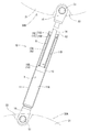
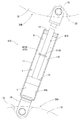
ダンパ10は、図1~図4に示すように、シリンダ11、ロッドガイド12、ピストン13、ロッド14、規制部である筒部材15、及び両端に設けられた2個のジョイント(joint)部16を有している。シリンダ11は有底筒状である。ロッドガイド12はシリンダ11の開口部を封鎖している。ピストン13はシリンダ11内に摺動自在に挿入されている。ロッド14は基端部がピストン13に連結されている。また、ロッド14はロッドガイド12を挿通して先端側がシリンダ11の外部へ突出している。ピストン13は、シリンダ11内をロッド14の基端部が収納されているロッド側圧力室11Bと、反ロッド側圧力室11Aとに仕切っている。ダンパ10はシリンダ11内に所定量の作動油Y及び所定量の圧縮ガスGを封入している。
規制部である筒部材15は、図3及び図4に示すように、略円筒状である。筒部材15は、円筒部15Aと、円筒部15Aの一方の端部に設けられた当接部15Bと、円筒部15Aの他方の端部に設けられた連結部15Cとを有している。円筒部15Aの内径はロッド14の外径よりも大きい。当接部15Bは円筒部15Aの一方の端部が内側に折れ曲がり形成されている。当接部15Bは中心にロッド14の外径よりも僅かに大きい内径を有する開口が形成された円環形状である。連結部15Cは、円筒部15Aの他方の端部が外側に折れ曲がり形成されている。連結部15Cは、シリンダ11の内径と略等しい外径を有した円環部15Dと、円環部15Dの外周縁から円筒部15Aと反対方向に伸びた円筒状の挟持部15Eとを具備している。筒部材15は、ロッド14を挿通した状態で、挟持部15Eがシリンダ11の内周面とロッドガイド12の外周面との間に挟持され、シリンダ11内に固定されている。つまり、規制部である筒部材15は、ロッド側圧力室11B内であって、ピストン13とロッドガイド12との間に配置されている。
このダンパ10を備えた転倒防止装置は、後述するように、シリンダ11の底部が開口部よりも下方に位置し、ロッド14がシリンダ11から上方に突出し、シリンダ11及びロッド14の中心軸が水平面に対して65°~75°の間の角度に傾斜した状態で、家具Fの上面と天井Cとの間に取り付けられる。シリンダ11及びロッド14の中心軸が水平面に対して65°~75°の間の角度に傾斜した状態で、圧縮ガスGよりも下方に封入された作動油Y内にピストン13が浸漬されるように、筒部材15はロッド14の中心軸に沿って所定の長さを有し、ピストン13の位置を規制している。つまり、このダンパ10は、ピストン13とロッドガイド12との間に介在する筒部材15の当接部15Bにピストン13が当接すると、それ以上にピストン13がロッドガイド12側に移動することができない。また、このダンパ10は、ピストン13が筒部材15の当接部15Bに当接した状態で、ピストン13は作動油Y内に浸漬した状態になる。このため、このダンパ10は全ストローク範囲でピストン13が作動油Y内を移動して減衰力を発揮することができる。
このダンパ10は伸長動作時に発生する減衰力が収縮動作時に発生する減衰力よりも小さい圧効きダンパである。ここで、ダンパ10の伸長動作とは、シリンダ11からロッド14の突出長さ及びダンパ10の長さが長くなっていく動作を意味する。また、ダンパ10の収縮動作とは、シリンダ11からロッド14の突出長さ及びダンパ10の長さが短くなっていく動作を意味する。また、ダンパ10はシリンダ11に封入した圧縮ガスGの膨張力が伸長方向に作用している。
ダンパ10の減衰力が発生するメカニズム(mechanism)は、周知の構造であるため、図示を省略して説明する。シリンダ11は、内部がピストン13によって、ロッド14の基端部が収納されているロッド側圧力室11Bと、反ロッド側圧力室11Aとに仕切られている。ピストン13は両圧力室間を連通させるオリフィス(orifice)が形成されている。オリフィスは、ダンパ10の伸縮動作に伴うロッド側圧力室11Bと反ロッド側圧力室11Aとの間の作動油Yの流れに抵抗を付与して減衰力を発生する減衰力発生部として機能する。また、ピストン13は逆止弁を介して両圧力室間を連通する連通路が形成されている。逆止弁は、ロッド側圧力室11Bから反ロッド側圧力室11Aへの作動油Yの流れを許容し、その逆の流れを阻止する。このため、ダンパ10は、伸長動作時、ロッド側圧力室11Bから反ロッド側圧力室11Aへの作動油Yの流路経路が、オリフィスと連通路の経路になる。一方、ダンパ10は、収縮動作時、反ロッド側圧力室11Aからロッド側圧力室11Bへの作動油Yの流路経路がオリフィスのみとなる。このため、ダンパ10は伸長動作時に発生する減衰力が収縮動作時に発生する減衰力よりも小さくなる。
各ジョイント部16は、図1~図4に示すように、平板状の金具を折り曲げて形成されている。また、各ジョイント部16はシリンダ11の底部とロッド14の先端部に接続されている。各ジョイント部16はダンパ10の軸線に直交する方向に貫通した貫通孔が形成されている。
一対のベース部30A,30Bは、図1及び図2に示すように、シリンダ11の底部に接続されたジョイント部16を連結した第1ベース部30Aであり、ロッド14の先端部に接続されたジョイント部16を連結した第2ベース部30Bである。第1ベース部30Aは家具Fの上面に当接して載置され、第2ベース部30Bは天井Cに当接する。第1ベース部30A及び第2ベース部30Bは同じ形態及び構造である。各ベース部30A,30Bは、ベース部本体31、回動軸部材であるボルト(bolt)51及びナット(nut)52、ブッシュ(bush)55、及び滑り止め部37を有している。
家具Fの上面に当接して載置された状態で第1ベース部30Aを上方から見た平面視において、ベース部本体31は長方形状の外形である(以下、この平面視におけるベース部本体31の外形において長辺が延びている方向を「長辺方向」と言い、短辺が延びている方向を「短辺方向」と言う。)。また、家具Fの上面に当接して載置された状態で第1ベース部30Aを短辺方向に見た側面視において、ベース部本体31は、下端縁が家具Fの上面に平行に直線状に伸びており、上端縁が下端縁の両側から上方に膨らんだ円弧状の外形である(図1参照)。また、家具Fの上面に当接して載置された状態で第1ベース部30Aを長辺方向に見た側面視において、ベース部本体31は下端縁よりも上端縁が短い略台形状の外形である(図2参照)。
家具Fの上面に当接して載置された状態の第1ベース部30Aにおいて、図2に示すように、ベース部本体31は上面に長辺方向(図1における左右方向であり、図2における奥行き方向)に伸びた溝部32が形成されている。
家具Fの上面に当接して載置された状態の第1ベース部30Aにおいて、図1~図4に示すように、ベース部本体31は、長辺方向の中央部であって、溝部32の両側に窪み部33が形成されている。この窪み部33は上方向と短辺方向の外方向に開口している。また、この窪み部33は短辺方向に貫通した挿通孔35が側面に開口している。また、この窪み部33は後述するボルト51の頭部51Aと、このボルト51にねじ込まれたナット52の夫々が配置される。また、この窪み部33は、ボルト51の頭部51Aとナット52に上方から工具が嵌合することができるように、長辺方向において上方に広がるように形成されている。
回動軸部材は、図2に示すように、ベース部本体31の挿通孔35の一方から挿入されたボルト51と、このボルト51の軸部51Bにねじ込まれたナット52とから構成されている。ボルト51の中心軸が各ベース部30A,30Bにおけるダンパ10の回動軸になる。
ブッシュ55は、図2に示すように、ダンパ10のジョイント部16に形成された貫通孔に取り付けられている。ブッシュ55はボルト51の軸部51B周りに回動自在である。また、このブッシュ55はボルト51の軸部51Bに対して傾くことができる。つまり、ブッシュ55をジョイント部16に取り付けたダンパ10は、ボルト51の軸部51B周りに回動自在であり、回動方向に交差する方向に揺動自在である。
滑り止め部37は、図1及び図2に示すように、ベース部本体31の外形に僅かに大きい相似形(長方形状)の外形である。滑り止め部37は弾性体である。また、滑り止め部37は、家具Fの上面に当接して載置された状態の第1ベース部30Aにおいて、ベース部本体31の下端開口に嵌合されている。また、滑り止め部37は略平板である。詳しくは、滑り止め部37は、家具Fの上面又は天井Cに当接する面が平坦である。滑り止め部37はその弾性力によってベース部本体31に着脱自在に取り付けられている。
このような構成を有する転倒防止装置は、シリンダ11の底部が開口部よりも下方に位置し、ロッド14がシリンダ11から上方に突出し、シリンダ11及びロッド14の中心軸が水平面に対して65°~75°の間の角度に傾斜するように、家具Fの上面と天井Cとの間に取り付けられる。このように転倒防止装置を家具Fの上面と天井Cとの間に取り付けると、ダンパ10のピストン13が作動油Y内に浸漬された状態になるため、地震等の揺れによって家具Fが傾いた際、この転倒防止装置は、ダンパ10が全ストローク範囲で減衰力を発揮し、常にダンパ10の減衰力が家具Fに作用して、家具Fの転倒を防止することができる。
したがって、実施形態1の転倒防止装置は家具の転倒を良好に防止することができる。
以上説明したように、この転倒防止装置を構成するダンパ10は、シリンダ11、ロッドガイド12、ピストン13、ロッド14、及び筒部材15を備えている。シリンダ11は有底筒状である。ロッドガイド12はシリンダ11の開口部を閉鎖している。ピストン13はシリンダ11内に摺動自在に収納されている。ロッド14は、基端部がピストン13に連結されており、ロッドガイド12を摺動自在に挿通して先端側がシリンダ11の外部に突出している。このダンパ10は、作動油Y及び圧縮ガスGをシリンダ11内に封入している。筒部材15は、シリンダ11の底部が開口部よりも下方に位置し、ロッド14がシリンダ11から上方に突出し、シリンダ11及びロッド14の中心軸が水平面に対して65°~75°の間の角度に傾斜した状態で、筒部材15が圧縮ガスGよりも下方に封入された作動油Y内にピストン13が浸漬されるようにピストン13の位置を規制している。
このダンパ10は、シリンダ11の底部が開口部よりも下方に位置し、ロッド14がシリンダ11から上方に突出し、シリンダ11及びロッド14の中心軸が水平面に対して65°~75°の間の角度に傾斜した状態で、筒部材15が圧縮ガスGよりも下方に封入された作動油Y内にピストン13が浸漬されるようにピストン13の位置を規制している。つまり、このダンパ10は、65°~75°の間の角度に傾斜した状態で、作動油Yよりも上方に封入された圧縮ガスG内にピストン13が移動しない。このため、このダンパ10は伸縮すると常にピストン13が作動油Y内を移動して減衰力を発揮することができる。
したがって、実施形態1のダンパ10は全ストローク範囲で減衰力を発揮することができる。
また、実施形態1のダンパ10において、シリンダ11は、ピストン13によって、ロッド14の基端部が収納されているロッド側圧力室11Bと、反ロッド側圧力室11Aとに内部が仕切られている。また、筒部材15は、ロッド側圧力室11B内であってピストン13とロッドガイド12との間に配置され、ロッド14の中心軸に沿って所定の長さを有している。このため、このダンパ10は、ピストン13とロッドガイド12との間に筒部材15が介在し、この筒部材15の当接部15Bにピストン13が当接すると、それ以上にピストン13がロッドガイド12側に移動することができない。つまり、このダンパ10は筒部材15が作動油Y内にピストン13が浸漬されるような長さを有してピストン13の位置を規制している。このため、このダンパ10は全ストローク範囲でピストン13が作動油Y内を移動して減衰力を発揮することができる。
<実施形態2>
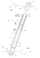
実施形態2の転倒防止装置は、図5及び図6に示すように、ダンパ110に備えられている規制部の形態が実施形態1と相違する。実施形態1と同じ構成は同じ符号を付し詳細な説明を省略する。
実施形態2の転倒防止装置は、図5及び図6に示すように、ダンパ110に備えられている規制部の形態が実施形態1と相違する。実施形態1と同じ構成は同じ符号を付し詳細な説明を省略する。
この転倒防止装置の規制部は、外形が円柱状であり、中心軸周りに中心軸方向に貫通した中心孔を有した袋体115である。この袋体115は内部にガスGが圧縮され充填されている。また、この袋体115は中心軸方向の長さを保持しつつ弾性変形する。この袋体115は、ガスGが圧縮され充填されているため、中心孔にロッド14を挿通した状態で、浮力によって、一方の端面がロッドガイド12に密着し、外周面がシリンダ11の内周面に密着している。このように、この転倒防止装置は規制部である袋体115をロッド側圧力室11Bに固定する手間を要しない。規制部である袋体115は、ロッド側圧力室11B内であって、ピストン13とロッドガイド12との間に配置されている。
このダンパ110は、図6に示すように、ダンパ110が収縮してピストン13が反ロッド側圧力室11A側に移動し、反ロッド側圧力室11A内の作動油Yがロッド側圧力室11B内に流入すると、ロッド側圧力室11B内に収納された規制部である袋体115が圧縮されロッド14の中心軸方向の長さを保持しつつ縮小する。このように、この袋体115はダンパ110の伸縮によって変化するシリンダ11内のロッド14の体積変化に追随してロッド14の中心軸方向の長さを保持しつつ弾性変形する。このダンパ110は、袋体115が縮小するにつれて袋体115の膨張力が増加し、この膨張力がダンパ110の伸長方向に作用する。
この転倒防止装置は、シリンダ11の底部が開口部よりも下方に位置し、ロッド14がシリンダ11から上方に突出し、シリンダ11及びロッド14の中心軸が水平面に対して65°~75°の間の角度に傾斜するように、家具Fの上面と天井Cとの間に取り付けられる。シリンダ11及びロッド14の中心軸が水平面に対して65°~75°の間の角度に傾斜した状態で、ガスGを圧縮して充填した袋体115よりも下方に封入された作動油Y内にピストン13が浸漬されるように、袋体115は、ロッド14の中心軸に沿って所定の長さを有し、ピストン13の位置を規制している。つまり、このダンパ110は、ピストン13とロッドガイド12との間に介在する袋体115にピストン13が当接すると、それ以上にピストン13がロッドガイド12側に移動することができない。このため、規制部である袋体115はダンパ110の伸長動作時のストッパとしても機能する。このダンパ110は、袋体115がストッパ(stopper)として機能し、ピストン13が袋体115に当接した際の接触音の発生を抑えることができる。また、このダンパ110は、ピストン13が袋体115に当接するため、作動油Y中にピストン13から金属片等のごみが発生することを抑えることができる。また、このダンパ110は、ピストン13が袋体115に当接した状態で、ピストン13は作動油Y内に浸漬した状態になる。このため、このダンパ110は全ストローク範囲でピストン13が作動油Y内を移動して減衰力を発揮することができる。また、このダンパ110は、袋体115にガスGを圧縮して充填し作動油Yと分離しているため、伸縮動作による気泡の発生を抑えることができる。
このように、この転倒防止装置は、ダンパ110のピストン13が作動油Y内に浸漬された状態で家具Fの上面と天井Cとの間に取り付けられるため、地震等の揺れによって家具Fが傾いた際、ダンパ110が全ストローク範囲で減衰力を発揮し、常にダンパの減衰力が家具Fに作用して、家具Fの転倒を防止することができる。
したがって、実施形態2の転倒防止装置は家具Fの転倒を良好に防止することができる。
また、実施形態2のダンパにおいて、規制部は、内部にガスGを圧縮して充填しており、ロッド14の中心軸方向の長さを保持しつつ弾性変形する袋体115である。このため、このダンパは、ピストン13とロッドガイド12との間に袋体115が介在し、この袋体115にピストン13が当接すると、それ以上にピストン13がロッドガイド12側に移動することができない。つまり、このダンパは規制部である袋体115が作動油Y内にピストン13が浸漬されるような長さを有してピストン13の位置を規制している。このため、このダンパ110は全ストローク範囲でピストン13が作動油Y内を移動して減衰力を発揮することができる。
<実施形態3>
実施形態3の転倒防止装置は、図7に示すように、ダンパ210に備えられている規制部の形態が実施形態1及び2と相違する。実施形態1及び2と同じ構成は同じ符号を付し詳細な説明を省略する。
実施形態3の転倒防止装置は、図7に示すように、ダンパ210に備えられている規制部の形態が実施形態1及び2と相違する。実施形態1及び2と同じ構成は同じ符号を付し詳細な説明を省略する。
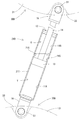
この転倒防止装置の規制部は、収納したピストン13よりロッドガイド12側のシリンダ211の内面から内方向に突出した凸部215である。この凸部215は、シリンダ211の側面の所定の位置を外側から内側に押圧して形成され、シリンダ211の内面を周方向に一周するように突出している。また、この凸部215が形成された部分のシリンダ211の内径は、ピストン13の外径よりも小さい。
この転倒防止装置は、シリンダ211の底部が開口部よりも下方に位置し、ロッド14がシリンダ211から上方に突出し、シリンダ211及びロッド14の中心軸が水平面に対して65°~75°の間の角度に傾斜するように、家具Fの上面と天井Cとの間に取り付けられる。シリンダ211及びロッド14の中心軸が水平面に対して65°~75°の間の角度に傾斜した状態で、規制部である凸部215は、圧縮ガスGよりも下方に封入された作動油Y内にピストン13が浸漬されるように、シリンダ211の所定の位置に形成され、ピストン13の位置を規制している。つまり、このダンパ210は、ピストン13の外周縁が凸部215に係止すると、それ以上にピストン13がロッドガイド12側に移動することができない。また、このダンパ210は、ピストン13の外周縁が凸部215に係止した状態で、ピストン13は作動油Y内に浸漬した状態になる。このため、このダンパ210は全ストローク範囲でピストン13が作動油Y内を移動して減衰力を発揮することができる。
このように、この転倒防止装置は、ダンパ210のピストン13が作動油Y内に浸漬された状態で家具Fの上面と天井Cとの間に取り付けられるため、地震等の揺れによって家具Fが傾いた際、ダンパ210が全ストローク範囲で減衰力を発揮し、常にダンパ210の減衰力が家具Fに作用して、家具Fの転倒を防止することができる。
したがって、実施形態3の転倒防止装置は家具Fの転倒を良好に防止することができる。
また、実施形態3のダンパ210において、規制部は、ピストン13よりロッドガイド12側のシリンダ211の内面から内方向に突出し、ピストン13の外周縁が係止する凸部215である。このため、ダンパ210は、シリンダ211の内面から内方向に突出した凸部215よりもロッドガイド12側にピストン13が移動することができない。つまり、このダンパ210は、規制部である凸部215が作動液体内にピストン13が浸漬される位置に設けられ、ピストン13の位置を規制している。このため、このダンパ210は全ストローク範囲でピストン13が作動液体Y内を移動して減衰力を発揮することができる。
<実施形態4>
実施形態4の転倒防止装置は、図8に示すように、ダンパ310に備えられている規制部の形態が実施形態1~3と相違する。実施形態1~3と同じ構成は同じ符号を付し詳細な説明を省略する。
実施形態4の転倒防止装置は、図8に示すように、ダンパ310に備えられている規制部の形態が実施形態1~3と相違する。実施形態1~3と同じ構成は同じ符号を付し詳細な説明を省略する。
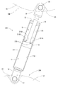
この転倒防止装置の規制部は、収納したピストン13よりもロッドガイド12側のシリンダ内に固定され、中央にロッド14を挿通する挿通孔315Aが形成された円環部材315である。この円環部材315は外径がシリンダ311の内径よりも僅かに小さい。この円環部材315は、シリンダ311の側面の所定の位置を外側から内側に絞って形成され、シリンダ311の内周面を周方向に一周するように突出した凸部311Aに外周縁が係止し、固定されている。
この転倒防止装置は、シリンダ311の底部が開口部よりも下方に位置し、ロッド14がシリンダ311から上方に突出し、シリンダ311及びロッド14の中心軸が水平面に対して65°~75°の間の角度に傾斜するように、家具Fの上面と天井Cとの間に取り付けられる。シリンダ311及びロッド14の中心軸が水平面に対して65°~75°の間の角度に傾斜した状態で、規制部である円環部材315は、圧縮ガスGよりも下方に封入された作動油Y内にピストン13が浸漬されるように、シリンダ311の所定の位置に固定され、ピストン13の位置を規制している。つまり、このダンパ310は、ピストン13が円環部材315に当接すると、それ以上にピストン13がロッドガイド12側に移動することができない。また、このダンパ310は、ピストン13が円環部材315に当接した状態で、ピストン13は作動油Y内に浸漬した状態になる。このため、このダンパ310は全ストローク範囲でピストン13が作動油Y内を移動して減衰力を発揮することができる。
このように、この転倒防止装置は、ダンパ310のピストン13が作動油Y内に浸漬された状態で家具Fの上面と天井Cとの間に取り付けられるため、地震等の揺れによって家具Fが傾いた際、ダンパ310が全ストローク範囲で減衰力を発揮し、常にダンパ310の減衰力が家具Fに作用して、家具Fの転倒を防止することができる。
したがって、実施形態4の転倒防止装置は家具Fの転倒を良好に防止することができる。
また、実施形態4のダンパ310において、規制部は、ピストン13よりもロッドガイド12側のシリンダ311内に固定され、中央にロッド14を挿通する挿通孔315Aが形成された円環部材315である。このため、ダンパ310は、シリンダ311内に固定された円環部材315よりもロッドガイド12側にピストン13が移動することができない。つまり、このダンパ310は、規制部である円環部材315が作動油Y内にピストン13が浸漬される位置に固定されピストン13の位置を規制している。このため、このダンパ310は全ストローク範囲でピストン13が作動油Y内を移動して減衰力を発揮することができる。
<実施形態5>
実施形態5の転倒防止装置は、図9及び図10に示すように、ダンパ410に備えられている規制部の形態が実施形態1~4と相違する。実施形態1~4と同じ構成は同じ符号を付し詳細な説明を省略する。
実施形態5の転倒防止装置は、図9及び図10に示すように、ダンパ410に備えられている規制部の形態が実施形態1~4と相違する。実施形態1~4と同じ構成は同じ符号を付し詳細な説明を省略する。
この転倒防止装置の規制部は、ロッド414の外周面から外方向に突出した鍔部415である。この鍔部415はロッドガイド12のピストン13側の側面に係止する。この鍔部415は、ロッド414の中心軸方向の所定の位置の外周面を一周する溝部414Aが形成され、この溝部にロッド414の外径よりも大きい外径を有するC型ワッシャ(washer)415Aを嵌め込んで形成されている。
この転倒防止装置は、シリンダ11の底部が開口部よりも下方に位置し、ロッド414がシリンダ11から上方に突出し、シリンダ11及びロッド414の中心軸が水平面に対して65°~75°の間の角度に傾斜するように、家具Fの上面と天井Cとの間に取り付けられる。シリンダ11及びロッド414の中心軸が水平面に対して65°~75°の間の角度に傾斜した状態で、規制部である鍔部415は、圧縮ガスGよりも下方に封入された作動油Y内にピストン13が浸漬されるように、ロッド414の所定の位置に形成され、ピストン13の位置を規制している。つまり、このダンパ410は、図9に示すように、鍔部415がロッドガイド12のピストン13側の側面に係止すると、それ以上にピストン13がロッドガイド12側に移動することができない。また、このダンパ410は、鍔部415がロッドガイド12のピストン13側の側面に係止した状態で、ピストン13は作動油Y内に浸漬した状態になる。このため、このダンパ410は全ストローク範囲でピストン13が作動油Y内を移動して減衰力を発揮することができる。
このように、この転倒防止装置は、ダンパ410のピストン13が作動油Y内に浸漬された状態で家具Fの上面と天井Cとの間に取り付けられるため、地震等の揺れによって家具Fが傾いた際、ダンパ410が全ストローク範囲で減衰力を発揮し、常にダンパ410の減衰力が家具Fに作用して、家具Fの転倒を防止することができる。
したがって、実施形態5の転倒防止装置は家具Fの転倒を良好に防止することができる。
また、実施形態5のダンパ410において、規制部は、ロッド414の外周面から外方向に突出し、ロッドガイド12のピストン13側の側面に係止する鍔部である。このため、ダンパ410は、ロッド414の外周面から外方向に突出した鍔部415がロッドガイド12のピストン13側の側面に係止すると、ピストン13がロッドガイド12側に移動することができない。つまり、このダンパ410は、規制部である鍔部415が作動油Y内にピストン13が浸漬される位置に設けられピストン13の位置を規制している。このため、このダンパ410は全ストローク範囲でピストン13が作動油Y内を移動して減衰力を発揮することができる。
本発明は上記記述及び図面によって説明した実施形態1~5に限定されるものではなく、例えば次のような実施形態も本発明の技術的範囲に含まれる。
(1)実施形態1~5では、シリンダ内に作動油を封入したが、作動油に限らず液体であればよい。
(2)実施形態1及び2では、規制部である筒部材又は袋体をシリンダ内に固定したが、ピストンとロッドガイドとの間に配置すれば、固定しなくてもよい。
(3)実施形態1では、規制部が筒状であったが、ロッドに沿って伸び、ピストンとロッドガイドとの間に挟持され、ピストンの位置を規制するものであれば、棒状等の他の形状であってもよい。
(4)実施形態2では、規制部である袋体の外形が円柱状であり、中心孔を有していたが、ピストンとロッドガイドとの間でロッド14に沿って伸びた複数の袋体であってもよい。
(5)実施形態3では、規制部である凸部をシリンダの側面を外側から内側に押圧して形成したが、凸部を他の方法で形成してもよい。
(6)実施形態3では、規制部である凸部をシリンダの内面を周方向に一周するように突出させたが、同一周面上に間隔をあけて凸部を形成してもよい。
(7)実施形態4では、規制部である円環部材をシリンダの内周面を周方向に一周する凸部に係止して固定したが、凸部を設けずに円環部材をシリンダ内に固定してもよい。
(8)実施形態5では、規制部である鍔部をロッドガイドに溝部を形成し、その溝部にC型ワッシャを嵌め込んで形成したが、他の方法で鍔部を形成してもよい。
(9)実施形態1、3~5では、シリンダ内に圧縮ガスを封入したが、シリンダ内に圧縮していないガスを封入してもよい。
(1)実施形態1~5では、シリンダ内に作動油を封入したが、作動油に限らず液体であればよい。
(2)実施形態1及び2では、規制部である筒部材又は袋体をシリンダ内に固定したが、ピストンとロッドガイドとの間に配置すれば、固定しなくてもよい。
(3)実施形態1では、規制部が筒状であったが、ロッドに沿って伸び、ピストンとロッドガイドとの間に挟持され、ピストンの位置を規制するものであれば、棒状等の他の形状であってもよい。
(4)実施形態2では、規制部である袋体の外形が円柱状であり、中心孔を有していたが、ピストンとロッドガイドとの間でロッド14に沿って伸びた複数の袋体であってもよい。
(5)実施形態3では、規制部である凸部をシリンダの側面を外側から内側に押圧して形成したが、凸部を他の方法で形成してもよい。
(6)実施形態3では、規制部である凸部をシリンダの内面を周方向に一周するように突出させたが、同一周面上に間隔をあけて凸部を形成してもよい。
(7)実施形態4では、規制部である円環部材をシリンダの内周面を周方向に一周する凸部に係止して固定したが、凸部を設けずに円環部材をシリンダ内に固定してもよい。
(8)実施形態5では、規制部である鍔部をロッドガイドに溝部を形成し、その溝部にC型ワッシャを嵌め込んで形成したが、他の方法で鍔部を形成してもよい。
(9)実施形態1、3~5では、シリンダ内に圧縮ガスを封入したが、シリンダ内に圧縮していないガスを封入してもよい。
10,110,210,301,410…ダンパ、11,211,311…シリンダ、11A…反ロッド側圧力室、11B…ロッド側圧力室、12…ロッドガイド、13…ピストン、14,414…ロッド、15,115,215,315,415…規制部(15…筒部材、115…袋体、215…凸部、315…円環部材、415…鍔部)、C…天井、F…家具(物品)、G…ガス(圧縮ガス)、Y…作動油(作動液体)
Claims (7)
- 有底筒状のシリンダと、
前記シリンダの開口部を封鎖したロッドガイドと、
前記シリンダ内に摺動自在に収納されたピストンと、
基端部が前記ピストンに連結されており、前記ロッドガイドを摺動自在に挿通して先端側が前記シリンダの外部へ突出したロッドと、
を備え、
前記シリンダ内に作動液体及びガスを封入しており、
前記シリンダの底部が開口部よりも下方に位置して前記ロッドが前記シリンダから上方に突出し、前記シリンダ及び前記ロッドの中心軸が水平面に対して所定の角度に傾斜した状態で、前記ガスよりも下方に封入された前記作動液体内に前記ピストンが浸漬されるように前記ピストンの位置を規制する規制部を備えていることを特徴とするダンパ。 - 前記シリンダは、前記ピストンによって、前記ロッドの基端部が収納されているロッド側圧力室と、反ロッド側圧力室とに内部が仕切られており、
前記規制部は、前記ロッド側圧力室内であって前記ピストンと前記ロッドガイドとの間に配置され、前記ロッドの中心軸に沿って所定の長さを有していることを特徴とする請求項1記載のダンパ。 - 前記規制部は、内部に前記ガスを圧縮して充填しており、前記ロッドの中心軸方向の長さを保持しつつ弾性変形する袋体であることを特徴とする請求項2記載のダンパ。
- 前記規制部は、前記ピストンより前記ロッドガイド側の前記シリンダの内面から内方向に突出し、前記ピストンの外周縁が係止する凸部であることを特徴とする請求項1記載のダンパ。
- 前記規制部は、前記ピストンよりも前記ロッドガイド側の前記シリンダ内に固定され、中央に前記ロッドを挿通する挿通孔が形成された円環部材であることを特徴とする請求項1記載のダンパ。
- 前記規制部は、前記ロッドの外周面から外方向に突出し、前記ロッドガイドの前記ピストン側の側面に係止する鍔部であることを特徴とする請求項1記載のダンパ。
- 前記シリンダの底部が開口部よりも下方に位置し、前記ロッドが前記シリンダから上方に突出し、前記シリンダ及び前記ロッドの中心軸が水平面に対して所定の角度に傾斜した状態で設置面上に設置された部品の上面と天井との間に取り付けられる請求項1乃至6のいずれか1項記載のダンパを備えていることを特徴とする転倒防止装置。
Priority Applications (2)
| Application Number | Priority Date | Filing Date | Title |
|---|---|---|---|
| US16/074,898 US20190040923A1 (en) | 2016-02-19 | 2017-01-06 | Damper and overturn preventing device equipped with the damper |
| CN201780008429.7A CN108603557A (zh) | 2016-02-19 | 2017-01-06 | 阻尼器以及具备该阻尼器的翻倒防止装置 |
Applications Claiming Priority (2)
| Application Number | Priority Date | Filing Date | Title |
|---|---|---|---|
| JP2016029567A JP6722468B2 (ja) | 2016-02-19 | 2016-02-19 | ダンパ及びこのダンパを備えた転倒防止装置 |
| JP2016-029567 | 2016-02-19 |
Publications (1)
| Publication Number | Publication Date |
|---|---|
| WO2017141563A1 true WO2017141563A1 (ja) | 2017-08-24 |
Family
ID=59625914
Family Applications (1)
| Application Number | Title | Priority Date | Filing Date |
|---|---|---|---|
| PCT/JP2017/000241 Ceased WO2017141563A1 (ja) | 2016-02-19 | 2017-01-06 | ダンパ及びこのダンパを備えた転倒防止装置 |
Country Status (5)
| Country | Link |
|---|---|
| US (1) | US20190040923A1 (ja) |
| JP (1) | JP6722468B2 (ja) |
| CN (1) | CN108603557A (ja) |
| TW (1) | TW201736751A (ja) |
| WO (1) | WO2017141563A1 (ja) |
Cited By (2)
| Publication number | Priority date | Publication date | Assignee | Title |
|---|---|---|---|---|
| US10452080B1 (en) | 2018-05-21 | 2019-10-22 | International Business Machines Corporation | Self-actuating device for facilitating preventing product tip over |
| US10743666B2 (en) | 2018-09-21 | 2020-08-18 | International Business Machines Corporation | Self-acting device for facilitating preventing product tip over |
Families Citing this family (1)
| Publication number | Priority date | Publication date | Assignee | Title |
|---|---|---|---|---|
| CN110720751B (zh) * | 2019-11-14 | 2021-12-03 | 宁波福玛特金属制品实业有限公司 | 一体化物证受理台 |
Citations (4)
| Publication number | Priority date | Publication date | Assignee | Title |
|---|---|---|---|---|
| JPS61119638U (ja) * | 1985-01-14 | 1986-07-28 | ||
| JPS636240U (ja) * | 1986-06-30 | 1988-01-16 | ||
| JPH08177926A (ja) * | 1994-12-28 | 1996-07-12 | Endless Sports:Kk | 車両用ショックアブソーバー |
| JP2015006330A (ja) * | 2013-05-29 | 2015-01-15 | カヤバ工業株式会社 | 転倒防止装置 |
Family Cites Families (2)
| Publication number | Priority date | Publication date | Assignee | Title |
|---|---|---|---|---|
| JPS6095311U (ja) * | 1983-12-08 | 1985-06-28 | 日産自動車株式会社 | ストラツト式懸架装置 |
| JP5601483B2 (ja) * | 2008-05-12 | 2014-10-08 | 美和ロック株式会社 | シリンダ装置及びドアクローザ |
-
2016
- 2016-02-19 JP JP2016029567A patent/JP6722468B2/ja active Active
-
2017
- 2017-01-06 US US16/074,898 patent/US20190040923A1/en not_active Abandoned
- 2017-01-06 WO PCT/JP2017/000241 patent/WO2017141563A1/ja not_active Ceased
- 2017-01-06 CN CN201780008429.7A patent/CN108603557A/zh not_active Withdrawn
- 2017-02-09 TW TW106104264A patent/TW201736751A/zh unknown
Patent Citations (4)
| Publication number | Priority date | Publication date | Assignee | Title |
|---|---|---|---|---|
| JPS61119638U (ja) * | 1985-01-14 | 1986-07-28 | ||
| JPS636240U (ja) * | 1986-06-30 | 1988-01-16 | ||
| JPH08177926A (ja) * | 1994-12-28 | 1996-07-12 | Endless Sports:Kk | 車両用ショックアブソーバー |
| JP2015006330A (ja) * | 2013-05-29 | 2015-01-15 | カヤバ工業株式会社 | 転倒防止装置 |
Cited By (4)
| Publication number | Priority date | Publication date | Assignee | Title |
|---|---|---|---|---|
| US10452080B1 (en) | 2018-05-21 | 2019-10-22 | International Business Machines Corporation | Self-actuating device for facilitating preventing product tip over |
| US10606284B2 (en) | 2018-05-21 | 2020-03-31 | International Business Machines Corporation | Self-actuating device for facilitating preventing product tip over |
| US10768640B2 (en) | 2018-05-21 | 2020-09-08 | International Business Machines Corporation | Self-actuating device for facilitating preventing product tip over |
| US10743666B2 (en) | 2018-09-21 | 2020-08-18 | International Business Machines Corporation | Self-acting device for facilitating preventing product tip over |
Also Published As
| Publication number | Publication date |
|---|---|
| TW201736751A (zh) | 2017-10-16 |
| US20190040923A1 (en) | 2019-02-07 |
| JP2017145929A (ja) | 2017-08-24 |
| JP6722468B2 (ja) | 2020-07-15 |
| CN108603557A (zh) | 2018-09-28 |
Similar Documents
| Publication | Publication Date | Title |
|---|---|---|
| CN106604662A (zh) | 翻倒防止装置及其安装方法 | |
| JP6353867B2 (ja) | 転倒防止装置 | |
| WO2017141563A1 (ja) | ダンパ及びこのダンパを備えた転倒防止装置 | |
| CN106714618A (zh) | 翻倒防止装置 | |
| JP5864068B1 (ja) | 転倒防止装置 | |
| KR20180040642A (ko) | 전도 방지 장치 및 그 설치 방법 | |
| US20190021499A1 (en) | Overturn preventing device | |
| WO2017169295A1 (ja) | ダンパ及びこのダンパを備えた転倒防止装置 | |
| JP6205445B2 (ja) | 転倒防止装置、及びその取り付け方法 | |
| JP6386087B2 (ja) | 制振棚 | |
| TW201713875A (zh) | 防傾倒裝置 | |
| JP6678025B2 (ja) | 転倒防止装置 | |
| JP6255458B1 (ja) | 転倒防止装置 | |
| JP6446589B1 (ja) | 転倒防止装置 | |
| JP2020010790A (ja) | 転倒防止装置 | |
| US20180271284A1 (en) | Overturn preventing device | |
| JP2017169853A (ja) | 転倒防止装置 | |
| JP2017169854A (ja) | 連結部材及び転倒防止装置 | |
| JP2017225539A (ja) | 転倒防止装置 | |
| JP2017176218A (ja) | 転倒防止装置 | |
| JP2020005848A (ja) | 転倒防止装置 | |
| TW201713874A (zh) | 防傾倒裝置 |
Legal Events
| Date | Code | Title | Description |
|---|---|---|---|
| 121 | Ep: the epo has been informed by wipo that ep was designated in this application |
Ref document number: 17752827 Country of ref document: EP Kind code of ref document: A1 |
|
| NENP | Non-entry into the national phase |
Ref country code: DE |
|
| 122 | Ep: pct application non-entry in european phase |
Ref document number: 17752827 Country of ref document: EP Kind code of ref document: A1 |