WO2017141523A1 - ウェーハの製造方法 - Google Patents
ウェーハの製造方法 Download PDFInfo
- Publication number
- WO2017141523A1 WO2017141523A1 PCT/JP2016/086451 JP2016086451W WO2017141523A1 WO 2017141523 A1 WO2017141523 A1 WO 2017141523A1 JP 2016086451 W JP2016086451 W JP 2016086451W WO 2017141523 A1 WO2017141523 A1 WO 2017141523A1
- Authority
- WO
- WIPO (PCT)
- Prior art keywords
- wire
- cutting
- ingot
- single crystal
- wafer
- Prior art date
- Legal status (The legal status is an assumption and is not a legal conclusion. Google has not performed a legal analysis and makes no representation as to the accuracy of the status listed.)
- Ceased
Links
Images



Classifications
-
- H—ELECTRICITY
- H10—SEMICONDUCTOR DEVICES; ELECTRIC SOLID-STATE DEVICES NOT OTHERWISE PROVIDED FOR
- H10P—GENERIC PROCESSES OR APPARATUS FOR THE MANUFACTURE OR TREATMENT OF DEVICES COVERED BY CLASS H10
- H10P54/00—Cutting or separating of wafers, substrates or parts of devices
-
- B—PERFORMING OPERATIONS; TRANSPORTING
- B24—GRINDING; POLISHING
- B24B—MACHINES, DEVICES, OR PROCESSES FOR GRINDING OR POLISHING; DRESSING OR CONDITIONING OF ABRADING SURFACES; FEEDING OF GRINDING, POLISHING, OR LAPPING AGENTS
- B24B27/00—Other grinding machines or devices
- B24B27/06—Grinders for cutting-off
-
- B—PERFORMING OPERATIONS; TRANSPORTING
- B28—WORKING CEMENT, CLAY, OR STONE
- B28D—WORKING STONE OR STONE-LIKE MATERIALS
- B28D5/00—Fine working of gems, jewels, crystals, e.g. of semiconductor material; apparatus or devices therefor
- B28D5/04—Fine working of gems, jewels, crystals, e.g. of semiconductor material; apparatus or devices therefor by tools other than rotary type, e.g. reciprocating tools
-
- H—ELECTRICITY
- H10—SEMICONDUCTOR DEVICES; ELECTRIC SOLID-STATE DEVICES NOT OTHERWISE PROVIDED FOR
- H10P—GENERIC PROCESSES OR APPARATUS FOR THE MANUFACTURE OR TREATMENT OF DEVICES COVERED BY CLASS H10
- H10P52/00—Grinding, lapping or polishing of wafers, substrates or parts of devices
-
- H—ELECTRICITY
- H10—SEMICONDUCTOR DEVICES; ELECTRIC SOLID-STATE DEVICES NOT OTHERWISE PROVIDED FOR
- H10P—GENERIC PROCESSES OR APPARATUS FOR THE MANUFACTURE OR TREATMENT OF DEVICES COVERED BY CLASS H10
- H10P90/00—Preparation of wafers not covered by a single main group of this subclass, e.g. wafer reinforcement
Definitions
- the present invention relates to a method for manufacturing a wafer.
- Patent Document 1 a method of reducing the amount of use by reusing wires when a wafer is manufactured by cutting a straight body portion of a single crystal ingot is known (see, for example, Patent Document 1).
- Patent Document 1 a wire obtained by cutting a single crystal ingot is used again, and when cutting the next single crystal ingot, the tension of the wire is set to 87% to 95% at the time of the previous cutting, and the supply amount of the wire ( A method is disclosed in which the length of the wire used for cutting one single crystal ingot is set to 125% or more of the supply amount at the previous cutting.
- this wear region includes a wire diameter stable region where the diameter is constant at a minimum value, and a region where cutting is performed before the wire diameter stable region.
- the single crystal ingot may be cut and the thickness in the wafer surface may vary.
- An object of the present invention is to provide a wafer manufacturing method capable of suppressing the amount of wire used and the variation in thickness within the wafer surface.
- the wafer manufacturing method of the present invention is a wafer manufacturing method for manufacturing a wafer by cutting a single crystal ingot using a wire saw, wherein the region used for cutting the first single crystal ingot in the wire of the wire saw is used. Among them, the second single crystal ingot is cut using only the wire diameter stable region where the wear amount is stable at the maximum value and the diameter is constant at the minimum value.
- the second single crystal ingot is cut using only the wire diameter stable region whose diameter is constant at the minimum value. Variation in thickness within the wafer surface obtained from the single crystal ingot 2 can be suppressed. In addition, since the wire used for cutting the first single crystal ingot is also used for cutting the second single crystal ingot, the amount of wire used can be suppressed.
- the second single crystal ingot is cut under a condition that the tension of the wire diameter stable region is smaller than the tension at the time of cutting the first single crystal ingot.
- the breaking load is smaller than that before wear. For this reason, if the second single crystal ingot is cut with a tension higher than that at the time of cutting the first single crystal ingot, the wire may be broken. According to the present invention, since the second single crystal ingot is cut with a tension smaller than that at the time of cutting the first single crystal ingot, wire breakage can be suppressed.
- the tension of the wire diameter stable region is set based on the breaking load and diameter of the wire before cutting the first single crystal ingot and the diameter of the wire diameter stable region. It is preferable.
- the wire may sway in the axial direction or the cutting direction of the single crystal ingot when the single crystal ingot is cut, and there is a possibility that the thickness variation in the wafer surface will increase.
- the breaking load in the wire diameter stable region is obtained, and the second single crystal ingot is obtained.
- the tension at the time of cutting can be increased to such an extent that the calculated breaking load is not exceeded and the wire is not shaken. Therefore, it is possible to suppress the disconnection of the wire and the increase in the thickness variation in the wafer surface regardless of the wear state of the wire.
- the second work is performed under a condition that the work per unit length of the wire diameter stable region is equal to or less than the work per unit length at the time of cutting the first single crystal ingot. It is preferable to cut the single crystal ingot.
- the work amount per unit length of the wire (hereinafter, “the work amount per unit length” may be simply referred to as “work amount”) is almost equal to the wear amount per unit length of the wire. Proportional. For this reason, as the work of the wire diameter stable region at the time of cutting the second single crystal ingot is increased, the wire diameter stable region becomes thinner, and the wire may be disconnected. According to the present invention, since the second single crystal ingot is cut with the following work amount when cutting the first single crystal ingot, the wire diameter stable region becomes too thin during the cutting, and the wire is disconnected. Can be suppressed.
- the wire is based on the total work amount of the region used for cutting the first single crystal ingot in the wire, the length of the region, and the length of the wire diameter stable region. It is preferable to set the total work amount in the diameter stable region.
- the total work amount of the region used for cutting the single crystal ingot in the wire is substantially proportional to the area and number of wafers obtained from the single crystal ingot. For this reason, if the set value of the total work amount in the wire diameter stable region is reduced more than necessary to prevent disconnection, a second single crystal ingot having a small diameter is prepared (the area of the wafer is reduced), the second Therefore, it is necessary to reduce the number of wafers obtained from the single crystal ingot.
- the maximum work amount of the wire diameter stable region is maximized. An allowable value is obtained, and within the range not exceeding the maximum allowable value, the number of wafers obtained from the second single crystal ingot can be increased or the area can be increased, and the manufacturing efficiency can be increased.
- the second single crystal ingot having a diameter smaller than that of the first single crystal ingot.
- the total work amount of the wire diameter stable region can be set by a simple method of selecting the second single crystal ingot having an appropriate diameter. Further, a wafer having a different diameter and a suppressed thickness variation can be obtained from the first single crystal ingot and the second single crystal ingot.
- the second single crystal ingot it is preferable to cut the second single crystal ingot shorter than the first single crystal ingot.
- the total work amount of the wire diameter stable region can be set by a simple method of simply selecting the second single crystal ingot having an appropriate length. Further, from the first single crystal ingot and the second single crystal ingot, a wafer having the same diameter and suppressed variation in thickness can be obtained.
- a plurality of the second single single ingots having the same diameter are sequentially cut under the same cutting conditions using only the wire diameter stable region. It is preferable to perform the step of sequentially cutting the crystal ingot.
- the positions of the wire diameter decreasing region, the wire diameter stable region, and the wire diameter increasing region after cutting the plurality of first single crystal ingots can be easily grasped, and the plurality of second single crystal ingots are obtained.
- the wire diameter stable region used for cutting can be easily specified, and the production efficiency can be increased.
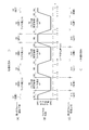
- the schematic diagram which shows the wire saw which concerns on one Embodiment of this invention. It is explanatory drawing of the manufacturing method of the wafer using the said wire saw, (A) is a 1st wafer manufacturing process, (B) is the shape of the wire after a 1st wafer manufacturing process, (C) is a 2nd wafer. A manufacturing process is shown. It is explanatory drawing of the manufacturing method of the wafer using the said wire saw, (A) is the positional relationship of an ingot and a wire, (B) is the relationship between the length of a wire, and the amount of wear, (C) is the length of a wire, and a wire The relationship with the diameter of is shown.
- (A) is a 1st wafer manufacturing process
- (B) is the shape of the wire after a 1st wafer manufacturing process
- (C) is 2nd.
- (D) shows another second wafer manufacturing process.
- (A) is the shape of the wire after a 1st wafer manufacturing process
- (B) is a 2nd wafer manufacturing process
- (C) is other A 2nd wafer manufacturing process is shown.
- the wire saw 1 includes a total of three main rollers 2 arranged on the same horizontal plane, two on the same horizontal plane and one below the middle of the two.
- a wire 7 is spirally wound around the three main rollers 2 along the axial direction.
- the wire 7 is made of a high-tensile plated steel wire generally called a piano wire. Both ends of the wire 7 are fixed to two bobbins 41 for feeding and winding the wire 7 through a plurality of guide rollers 31 and one tension roller 32 (one in FIG. 1). Yes.
- a traverser 42 is provided between the tension roller 32 and the bobbin 41.
- the traverser 42 has a function of adjusting the feeding position and winding position of the wire 7 with respect to the bobbin 41.
- nozzles 5 for supplying the slurry G to an intermediate position between the two upper main rollers 21 are provided above the two upper main rollers 2 (hereinafter referred to as the upper main roller 21).
- a feeding means 6 that holds and lifts a single crystal ingot (hereinafter simply referred to as “ingot”) M such as silicon, SiC, GaAs, or sapphire.
- the wafer manufacturing method includes a first wafer manufacturing step of sequentially cutting a plurality of first ingots having the same diameter under the same cutting conditions, and the first wafer manufacturing process. And a second wafer manufacturing process for sequentially cutting a plurality of second ingots using the wire 7 used in the wafer manufacturing process.
- the “wire position” on the horizontal axis represents a position when the predetermined position on the front end side of the wire 7 in the feed direction is set to 0 km. Further, in FIGS. 2A to 2C, a case where three each of the first and second ingots are cut will be described.
- the wire saw 1 is connected to the ingot M and the wire 7 in order to stabilize the thermal deformation of each member due to the operating heat of the wire saw 1 in the first wafer manufacturing process.
- the wire 7 is caused to travel while supplying (circulating) the slurry G in a state where it is not in contact (warming-up step S1).
- the wire saw 1 rotates the main roller 2 to cause the wire 7 to travel in one direction E1 shown in FIG. 1, and the vertical position of the tension roller 32 is set so that the tension of the wire 7 becomes T1.
- the slurry G is supplied between the two upper main rollers 21 after adjustment.
- the diameter of the wire 7 after the warm-up step S1 becomes the same DW1 as that of the new product as shown in FIG.
- the wire saw 1 After the warm-up step S1, the wire saw 1 lowers the first ingot M1 while maintaining the traveling speed, traveling direction, tension, and supply state of the slurry G of the wire 7, as shown in FIG.
- the first ingot M1 is cut by being pressed against the running wire 7, and a plurality of wafers are manufactured (cutting step S2).
- the contact portion between the wire 7 and the first ingot M1 has a contact length increasing region P1 where the contact length gradually increases, and a maximum value approximately.
- the wear amount of the wire 7 gradually increases in the contact length increasing region P1 and reaches the maximum value in the contact length stable region P2 from the start of cutting to the end of cutting. It becomes substantially constant at Ymax, and gradually decreases in the contact length reduction region P3.
- FIG. 3C when the first ingot M1 is cut with the wire 7 having a diameter DW1 and a length X1 as indicated by a one-dot chain line, the wire 7 is indicated by a solid line.
- the wire diameter decreasing region R1 in which the diameter gradually decreases As described above, the wire diameter decreasing region R1 in which the diameter gradually decreases, the wire diameter stable region R2 in which the diameter becomes the minimum value DW2 (DW1-Ymax) and the length is X2, and the wire in which the diameter gradually increases.
- a diameter increasing region R3 is formed.
- the wire saw 1 moves the wire 7 in the other direction E2 and pulls the wire 7 by raising the feeding means 6. At this time, since the wire diameter increasing region R3 thinner than the new product passes between the wafers, the wire 7 is not worn or the wafer is not scraped.
- the wire saw 1 After the cutting step S2, the wire saw 1 is in a state in which the first ingot M1 and the wire 7 are not brought into contact with each other for preparation up to the next cutting step, maintenance of the wire saw 1, etc., as shown in FIG. Then, the wire 7 is sent in one direction E1 (feeding step S3). At this time, since the wire 7 is not worn, as shown in FIG. 2B, the diameter of the wire 7 after the feeding step S3 becomes the same DW1 as that of the new product.
- the wire saw 1 repeats the cutting step S2 and the feeding step S3 according to the number of remaining first ingots M1 to be cut (two in this embodiment), and the first wafer manufacturing step is completed.
- the process flows from the process on the left side to the process on the right side in FIG. 2A.
- the wire 7 has positions L1 to L2, L5 to L6, and L9 to L10 at the wire diameters. It becomes the decrease region R1, the positions L2 to L3, L6 to L7, L10 to L11 become the wire diameter stable region R2, and the positions L3 to L4, L7 to L8, L11 to L12 become the wire diameter increase region R3. Further, the positions L0 to L1, L4 to L5, L8 to L9, and L12 to L13 become the unworn region R0 where the diameter of the wire 7 is the same as that of the new product.
- the wire diameter stable region R2 positions L2 to L3, L6 to L7, Since the wire length X2 of L10 to L11) is the same, the position of the wire diameter stable region R2 used for cutting the plurality of second ingots can be easily specified.
- the bobbin 41 that has wound the wire 7 in the first wafer manufacturing process is reset to another wire saw 1 used in the second wafer manufacturing process. Thereafter, the tension of the wire 7 is set. At this time, it is preferable to set the tension of the wire 7 so as to satisfy the following expression (2). As described above, the wire 7 can be prevented from being disconnected by cutting the second ingot under the condition that the tension of the wire diameter stable region R2 is smaller than the tension at the time of cutting the first ingot M1. T2 ⁇ T1 (2)
- T2 wire tension (N) in the second wafer manufacturing process
- F Breaking load (N) of a new wire (wire before cutting the first ingot)
- Sc2 Safety factor (where Sc2 ⁇ 1)
- DW1 Diameter of new wire (mm)
- DW2 Wire diameter stable region diameter (mm)
- the tension T2 of the wire 7 is The breaking load is not exceeded and the wire 7 can be increased to such an extent that the wire 7 does not shake during traveling, and it is possible to suppress disconnection of the wire 7 and increase in thickness variation in the wafer surface.
- the work amount of the wire diameter stable region R2 is set. At this time, it is preferable to cut the second ingot under the condition that the work amount of the wire diameter stable region R2 is equal to or less than the work amount at the time of cutting the first ingot M1. If it does in this way, it can control that wire diameter stable field R2 becomes thin too much during cutting, and wire 7 will break.
- the size and cutting conditions of the second ingot satisfy the following formula (4).
- the first ingot cutting total area A1 is substantially proportional to the total work amount of the region used for cutting the first ingot M1 in the wire 7.
- the second ingot cutting total area A2 is substantially proportional to the total work amount of the wire diameter stable region R2.
- the above formula (4) taking into account the first ingot cutting total area A1, the length X1 of the wire 7 used in the cutting step of the first ingot M1, and the length X2 of the wire diameter stable region R2
- the maximum allowable value of the second ingot cutting total area A2 is obtained, and the number of wafers obtained from the second ingot is increased or the area is increased within a range not exceeding the maximum allowable value. Manufacturing efficiency can be increased.
- a second ingot having a diameter smaller than the first ingot M1 a first shorter than the first ingot M1.
- Examples thereof include a method for selecting a second ingot having a diameter smaller than that of the first ingot M1 and the first ingot M1.
- a second ingot having a size taking into account the above equation (4) is attached to the feeding means 6.
- the wire saw 1 starts to feed the wire 7 from the rear end side in the feeding direction in the first wafer manufacturing process, for example, from the position L13 as shown in FIG. 2B, and uses only the wire diameter stable region R2. To cut the second ingot.
- the wire saw 1 performs a warm-up step S11 as shown in FIG.
- the wire 7 is sent from the position L13 to the position L11, but the diameter of the wire 7 does not change before and after the warm-up step S11.
- the wire saw 1 cuts the second ingot while maintaining the traveling speed, traveling direction, tension, and supply state of the slurry G of the wire 7 to manufacture a plurality of wafers (cutting step S12). .
- the wire diameter stable region R2 from the position L11 to the position L10 is used.
- region R2 wears similarly to the time of cutting process S2, and a wire diameter decreasing area
- the wire saw 1 causes the wire 7 to travel in the opposite direction and pulls the wire 7 by raising the feed means 6.
- the wire saw 1 After the cutting step S12, the wire saw 1 performs a feeding step S13 for sending the wire 7 from the position L10 to the position L7.
- the diameter of the wire 7 does not change before and after the feeding step S13.
- the wire saw 1 repeats the cutting step S12 using only the wire diameter stable region R2 and the feeding step S13 according to the number of second ingots to be cut, and the second wafer manufacturing step is completed.
- the process flows from the process on the right side of FIG. 2C to the process on the left side.
- a 160 km wire was used for cutting one first ingot M11, and three first ingots M11 having the same size could be cut with one wire.
- the wire diameter stable region R2 after the completion of the first wafer manufacturing process was 120 km. Further, the diameter of the wire diameter stable region R2 was 95% of the diameter of the unweared region R0.
- the bobbin around which the wire was wound was set again on another wire saw, and the second wafer manufacturing process was performed.
- the wire tension T2 was set based on the above formulas (2) and (3).
- the safety factor Sc2 is set to the same value as Sc1
- the tension T2 was set to 18N.
- the second ingot having a diameter of 200 mm and a length of 505 mm or less can be cut using only the 120 km wire diameter stable region R2.
- the wire tension T2 is set to 18N, and one second ingot M121 having a length of 505 mm or less is provided in each of the three wire diameter stable regions R2. A total of three can be cut at a time.
- the tension T2 is set to 18N, and in each of the wire diameter stable regions R2, two second ingots M122 each having a length of 252 mm or less are cut in a total of six. be able to.
- the second ingot having a diameter of 150 mm and a length of 898 mm or less can be cut using only the 120 km wire diameter stable region R2.
- the wire tension T2 is set to 18N, and two second ingots M123 having a length of 449 mm or less are provided in each of the three wire diameter stable regions R2. A total of six can be cut at a time.
- the tension T2 is set to 18N, and in each of the wire diameter stable regions R2, three second ingots M124 each having a length of 299 mm or less are cut in a total of nine. be able to.
- first ingots M1 having the same diameter are sequentially cut under the same cutting conditions, so that the wire diameter decreasing region R1, the wire diameter stable region R2, and the wire after the first wafer manufacturing process are cut.
- the position of the diameter increase region R3 can be easily grasped. Therefore, the wire diameter stable region R2 used in the second wafer manufacturing process can be easily specified, and the manufacturing efficiency can be increased.
- the tension T2 at the time of cutting the second ingot may be larger than the tension T1 at the time of cutting the first ingot as long as it is equal to or less than the breaking load of the wire diameter stable region R2.
- the tension T2 at the time of cutting the second ingot may be set to a default value equal to or less than the breaking load of the wire diameter stable region R2 without being set based on the formula (3). If the wire 7 does not break when the second ingot is cut, the second ingot may be cut under the condition that the work amount of the wire diameter stable region R2 is larger than the work amount when the first ingot M1 is cut. .
- the second ingot cutting total area A2 may be set to a default value so that the wire 7 does not break during the second ingot cutting without being set based on the equation (4).
- a plurality of first ingots M1 may be cut by changing at least one of the diameter and cutting conditions of the first ingot M1, and in this case, the first wafer manufacturing process What is necessary is just to perform the process which pinpoints wire diameter stable area
- the number of first ingots M1 cut using one wire 7 may be two or less, or four or more.
- the length of the second ingot may be different within a range where the total length is equal to or less than the length of the wire diameter stable region R2.
- the diameter of the second ingot may be the same or different.
- different wire saws 1 were used in the first wafer manufacturing process and the second wafer manufacturing process, the same one may be used.
- the wire 7 is moved in the reverse direction (the other direction).
- the second wafer manufacturing process may be performed while traveling in E2), or the second wafer manufacturing process may be performed while traveling in the other direction E2 and rewinding once and traveling in one direction E1.
- a second ingot having a diameter of 200 mm and a length of 450 mm satisfying the above formula (4) was prepared. Further, as shown in Table 1 below, the tension T2 was set to 18 N satisfying the above formulas (2) and (3). And the 2nd wafer manufacturing process which cut
- Example 1 ⁇ Comparative Example 1 ⁇ First, a new wire 500 km and an ingot similar to the second wafer manufacturing process of Example 1 were prepared. Since the new wire had no wear and the diameter was uniform over the entire area, the entire area was used without selecting the area of use. Then, as shown in Table 1, the tension was set to 20 N below the breaking load, and the ingot was usually cut under the conditions applied to a new wire to manufacture 450 wafers. The wire used for cutting the ingot was 65 km. Further, seven ingots were cut with one wire.
- Example 2 the wire obtained by performing the 1st wafer manufacturing process of Example 1 was prepared.
- the second wafer manufacturing process was performed under the same conditions as in Comparative Example 1, that is, the conditions normally applied to new wires, except that the obtained wires were used. That is, the second wafer manufacturing process was performed using the wire diameter decreasing region R1 or the wire diameter increasing region R3 in addition to the wire diameter stable region R2 without selecting the cutting use region.
- 450 wafers were manufactured from one second ingot, 65 km of wires were used for cutting, and 7 ingots were cut with one wire.
- the disconnection occurrence rate of Comparative Example 1 is at a level where there is no problem in terms of equipment operation loss due to operation stoppage, worker man-hours required for restoration, material loss when there is damage to secondary materials such as main rollers, etc. there were. As shown in Table 1, when the disconnection occurrence rate of Comparative Example 1 is 1, it is 3.0 or more and less than 6.0 in Comparative Example 2, whereas in Example 1, it is 1 or more and less than 1.1. there were.
- the tension T2 is set to 20 N as in the case of using a new wire, that is, the above formula Since it is set to be larger than the value 18N that satisfies (2) and (3), the wire use length X2 is 65 km as in the case of using a new wire, that is, shorter than the value 120 km that satisfies the above equation (4). Since the amount of wear of the wire increases by setting, it is considered that the wire diameter is easily broken in the wire diameter stable region R2, and the occurrence rate of breakage is 3.0 times or more and less than 6.0 times that of Comparative Example 1.
- Example 1 only the wire diameter stable region R2 is used for cutting the second ingot.
- the tension T2 is set to 18 N satisfying the above formulas (2) and (3)
- the use length X2 is set to 120 km that satisfies the above formula (4), it is difficult to break even in the wire diameter stable region R2, and the breakage occurrence rate is considered to be 1 to 1.1 times that of Comparative Example 1. It is done.
- Comparative Example 2 when the measured GBIR value of Comparative Example 1 was 1, it was 1.1 or more and less than 1.6 in Comparative Example 2, whereas in Example 1, it was 1 or more and less than 1.1.
- Comparative Example 2 in addition to the wire diameter stable region R2, the wire diameter decreasing region R1 or the wire diameter increasing region R3 is also used for cutting the second ingot, and one wafer is formed in regions having different wire diameters. It is considered that the wafer warpage and in-plane thickness variation were at a bad level because of being cut.
- the wire diameter stable region R2 is used for cutting the second ingot, and one wafer is cut in the region where the wire diameter is the same. It is thought that the level was satisfactory.
Landscapes
- Engineering & Computer Science (AREA)
- Mechanical Engineering (AREA)
- Mechanical Treatment Of Semiconductor (AREA)
- Processing Of Stones Or Stones Resemblance Materials (AREA)
- Finish Polishing, Edge Sharpening, And Grinding By Specific Grinding Devices (AREA)
Abstract
Description
特許文献1には、単結晶インゴットを切断したワイヤを再度用い、次の単結晶インゴットを切断する際に、ワイヤの張力を前回切断時の87%~95%にするとともに、ワイヤの供給量(単結晶インゴット1本の切断に用いられるワイヤの長さ)を前回切断時の供給量に対して125%以上にする方法が開示されている。
使用後のワイヤは、このように直径が一定でないことから、特許文献1に記載の方法のように、2回目の切断に用いるワイヤの長さを1回目よりも長くすると、直径が異なる領域で単結晶インゴットが切断されてしまい、ウェーハ面内の厚さがばらつくおそれがある。
本発明によれば、第1の単結晶インゴットの切断時より小さい張力で第2の単結晶インゴットを切断するため、ワイヤの断線を抑制できる。
本発明によれば、第1の単結晶インゴット切断前のワイヤの破断荷重および直径と、ワイヤ径安定領域の直径とに基づいて、ワイヤ径安定領域の破断荷重を求め、第2の単結晶インゴット切断時の張力を、この求めた破断荷重を超えず、かつ、ワイヤがぶれない程度まで大きくすることができる。したがって、ワイヤの摩耗状態にかかわらず、ワイヤの断線と、ウェーハ面内の厚さのばらつきが大きくなることとを抑制できる。
本発明によれば、第1の単結晶インゴットの切断時以下の仕事量で、第2の単結晶インゴットを切断するため、切断中にワイヤ径安定領域が細くなりすぎて、ワイヤが断線してしまうことを抑制できる。
本発明によれば、第1の単結晶インゴットの切断に用いた領域の総仕事量および当該領域の長さと、ワイヤ径安定領域の長さとに基づいて、ワイヤ径安定領域の総仕事量の最大許容値を求め、この最大許容値を超えない範囲で、第2の単結晶インゴットから得られるウェーハの枚数を多くしたり、面積を大きくしたりすることができ、製造効率を高めることができる。
[ワイヤソーの構成]
まず、ワイヤソーの構成について説明する。
図1に示すように、ワイヤソー1は、同一水平面上に2個、これら2個の中間の下方に1個配置された合計3個のメインローラ2を備えている。これら3個のメインローラ2の周りには、軸方向に沿ってワイヤ7が螺旋状に巻き付けられている。ワイヤ7は、一般的にピアノ線と呼ばれる高張力メッキ鋼線により構成されている。ワイヤ7の両端側は、それぞれ複数ずつ(図1では、1個ずつ図示)のガイドローラ31およびテンションローラ32を介して、ワイヤ7を送り出したり巻き取ったりする2個のボビン41に固定されている。また、テンションローラ32とボビン41との間には、それぞれトラバーサ42が設けられている。トラバーサ42は、ワイヤ7のボビン41に対する送り出し位置、巻取り位置を調整する機能を有している。さらに、上側の2個のメインローラ2(以下、上側メインローラ21と称す)の上方には、2個の上側メインローラ21の中間位置にスラリーGを供給するノズル5がそれぞれ設けられている。また、ノズル5の上方には、シリコン、SiC、GaAs、サファイア等の単結晶インゴット(以下、単に「インゴット」と言う)Mを保持して昇降させる送り手段6が設けられている。
次に、ワイヤソー1を用いたインゴットMの切断によりウェーハを製造する方法について説明する。
図2(A)~(C)に示すように、ウェーハの製造方法は、同じ直径の複数の第1のインゴットを、同じ切断条件で順次切断する第1のウェーハ製造工程と、この第1のウェーハ製造工程に用いられたワイヤ7を用い、複数の第2のインゴットを順次切断する第2のウェーハ製造工程とを備えている。
なお、図2(A),(C)において、横軸の「ワイヤの位置」とは、ワイヤ7の送り方向先端側の所定位置を0kmとしたときの位置を表す。また、図2(A)~(C)では、それぞれ3本ずつの第1,第2のインゴットを切断する場合について説明する。
第1のウェーハ製造工程では、まず、ワイヤ7の張力を以下の式(1)を満たすように設定する。なお、安全係数Sc1を大きくするほど、張力T1が小さくなり、ワイヤ7が断線しにくくなる。
T1=F/Sc1 … (1)
T1 :第1のウェーハ製造工程でのワイヤの張力(N)
F :新品ワイヤ(第1のインゴット切断前のワイヤ)の破断荷重(N)
Sc1:安全係数(ただし、Sc1≧1)
このとき、ワイヤ7は摩耗しないため、図2(B)に示すように、暖機工程S1後のワイヤ7の直径は、新品と同じDW1になる。
この切断工程において、図3(A)に示すように、ワイヤ7と第1のインゴットM1との接触部分には、接触長さが徐々に増加する接触長さ増加領域P1と、最大値で略一定となる接触長さ安定領域P2と、徐々に減少する接触長さ減少領域P3とが存在することになる。
接触長さが大きくなるほど、ワイヤ7に作用する反力が増大し、ワイヤ7に対する負荷は大きくなり、ワイヤ7の摩耗量は大きくなる。このため、図3(B)に示すように、切断開始から切断終了にかけて、ワイヤ7の摩耗量は、接触長さ増加領域P1においては徐々に増加し、接触長さ安定領域P2においては最大値Ymaxで略一定となり、接触長さ減少領域P3においては徐々に減少する。
その結果、図3(C)に示すように、一点鎖線で表すようなワイヤの直径がDW1、長さがX1のワイヤ7で第1のインゴットM1を切断すると、ワイヤ7には、実線で示すように、直径が徐々に減少するワイヤ径減少領域R1と、直径が最小値DW2(DW1-Ymax)で略一定となり、長さがX2のワイヤ径安定領域R2と、直径が徐々に増加するワイヤ径増加領域R3とが形成されることとなる。
第2のウェーハ製造工程では、まず、第1のウェーハ製造工程でワイヤ7を巻き取ったボビン41を、第2のウェーハ製造工程で用いる他のワイヤソー1にセットし直す。その後、ワイヤ7の張力を設定する。この際、以下の式(2)を満たすように、ワイヤ7の張力を設定することが好ましい。このように、ワイヤ径安定領域R2の張力が第1のインゴットM1切断時の張力よりも小さい条件で、第2のインゴットを切断することにより、ワイヤ7の断線を抑制できる。
T2≦T1 … (2)
T2≦F/Sc2×(DW2/DW1)2 … (3)
T2 :第2のウェーハ製造工程でのワイヤの張力(N)
F :新品ワイヤ(第1のインゴット切断前のワイヤ)の破断荷重(N)
Sc2:安全係数(ただし、Sc2≧1)
DW1:新品ワイヤの直径(mm)
DW2:ワイヤ径安定領域の直径(mm)
A2≦A1×X2/X1 … (4)
A2:1本の第2のインゴット切断総面積(mm2)
(1本の第2のインゴットから得られる1枚のウェーハの面積×
(1本の第2のインゴットから得られるウェーハの枚数-1))
A1:1本の第1のインゴット切断総面積(mm2)
(1本の第1のインゴットから得られる1枚のウェーハの面積×
(1本の第1のインゴットから得られるウェーハの枚数-1))
X2:1つのワイヤ径安定領域の長さ(km)
X1:1本の第1のインゴットの切断に用いたワイヤの長さ(km)
例えば、上記式(4)を満たす範囲で第2のインゴット切断総面積A2を設定する方法としては、第1のインゴットM1よりも直径が小さい第2のインゴット、第1のインゴットM1よりも短い第2のインゴット、第1のインゴットM1よりも直径が小さくかつ短い第2のインゴットを選択する方法などが例示できる。
また、第2のインゴットの切断が終了すると、ワイヤソー1は、ワイヤ7を逆方向に走行させるとともに、送り手段6を上昇させることでワイヤ7を引き抜く。
〔適用例1〕
次に、直径300mmの第1のインゴットの切断に使用したワイヤを、直径200mmの第2のインゴットの切断に使用する場合について説明する。
図4(A)に示す第1のウェーハ製造工程において、ワイヤを500km準備した。また、直径300mm、長さ300mmの第1のインゴットM11を準備した。
そして、図1に示すようなワイヤソーを用い、ワイヤの張力T1を破断荷重以下の20Nに設定し、第1のインゴットM11を切断ピッチ1mmで切断することで、300枚のウェーハを製造した。1本の第1のインゴットM11の切断に160kmのワイヤを使用し、1本のワイヤで、同じ大きさの第1のインゴットM11を3本切断することができた。
第1のウェーハ製造工程終了後のワイヤ径安定領域R2は、図4(B)に示すように、120kmであった。また、ワイヤ径安定領域R2の直径は、未摩耗領域R0の直径の95%であった。
まず、上記式(2),(3)に基づいて、ワイヤの張力T2を設定した。この際、安全係数Sc2をSc1と同じ値にすると、式(3)の計算結果は、
T2≦18.05N(=20×(95/100)2)
となったので、張力T2を18Nに設定した。
A1=6727500π(=1502×π×(300-1))
X2=120
X1=160
であり、1本の第2のインゴットから得られるウェーハの枚数をNwとすると、
A2=1002×π×(Nw-1)
となる。これらの値を式(4)に代入すると、
Nw≦505.5625
となる。
以上のことから、図4(C)に示すように、ワイヤの張力T2を18Nに設定し、3箇所のワイヤ径安定領域R2のそれぞれにおいて、長さ505mm以下の第2のインゴットM121を1本ずつ、合計3本切断することができる。
また、図4(D)に示すように、張力T2を18Nに設定し、各ワイヤ径安定領域R2のそれぞれにおいて、長さ252mm以下の第2のインゴットM122を2本ずつ、合計6本切断することができる。
次に、適用例1の第1のウェーハ製造工程で得られたワイヤを、直径150mmの第2のインゴットの切断に使用する場合について説明する。
図5(A)に示すように、図4(B)と同じ形状のワイヤを巻き取ったボビンを、別のワイヤソーにセットし直し、第2のウェーハ製造工程を行った。
まず、ワイヤの張力T2を、適用例1と同じ18Nに設定した。
また、上記式(4)に基づいて、切断可能な第2のインゴットの長さを求めた。式(4)のA1、X2、X1は、それぞれ適用例1と同じ6727500π、120、160であり、1本の第2のインゴットから得られるウェーハの枚数をNwとすると、
A2=752×π×(Nw-1)
となる。これらの値を式(4)に代入すると、
Nw≦898
となる。
以上のことから、図5(B)に示すように、ワイヤの張力T2を18Nに設定し、3箇所のワイヤ径安定領域R2のそれぞれにおいて、長さ449mm以下の第2のインゴットM123を2本ずつ、合計6本切断することができる。
また、図5(C)に示すように、張力T2を18Nに設定し、各ワイヤ径安定領域R2のそれぞれにおいて、長さ299mm以下の第2のインゴットM124を3本ずつ、合計9本切断することができる。
上述したように、第1のインゴットM1切断後のワイヤ7のうち、ワイヤ径安定領域R2のみを用いて第2のインゴットを切断するため、第2のインゴットから得られるウェーハ面内の厚さのばらつきを抑制できる。また、第1のインゴットM1の切断に用いられたワイヤ7を第2のインゴットの切断にも用いるため、ワイヤ7の使用量も抑制できる。
なお、本発明は上記実施形態にのみ限定されるものではなく、本発明の要旨を逸脱しない範囲内において種々の改良ならびに設計の変更などが可能であり、その他、本発明の実施の際の具体的な手順、及び構造などは本発明の目的を達成できる範囲で他の構造などとしてもよい。
第2のインゴット切断時の張力T2を、式(3)に基づき設定せずに、ワイヤ径安定領域R2の破断荷重以下のデフォルト値に設定してもよい。
第2のインゴット切断時にワイヤ7が断線しない条件であれば、ワイヤ径安定領域R2の仕事量が第1のインゴットM1切断時の仕事量より大きい条件で、第2のインゴットを切断してもよい。
第2のインゴット切断総面積A2を、式(4)に基づき設定せずに、第2のインゴット切断時にワイヤ7が断線しないようなデフォルト値に設定してもよい。
第1のウェーハ製造工程において、第1のインゴットM1の直径および切断条件のうち少なくとも一方を異ならせて、複数の第1のインゴットM1を切断してもよく、この場合、第1のウェーハ製造工程中やその後にワイヤ径安定領域R2を特定する処理を行えばよい。
1箇所のワイヤ径安定領域R2で複数の第2のインゴットを切断する場合、第2のインゴットの長さは、合計長さがワイヤ径安定領域R2の長さ以下となる範囲で異なっていてもよく、この場合、第2のインゴットの直径は同じでもよいし、異なっていてもよい。
第1のウェーハ製造工程と第2のウェーハ製造工程とで違うワイヤソー1を用いたが、同じものを用いてもよく、この場合、第1のウェーハ製造工程後、ワイヤ7を逆方向(他方向E2)に走行させながら第2のウェーハ製造工程を行ってもよいし、他方向E2に走行させて一度巻き戻し、一方向E1に走行させながら第2のウェーハ製造工程を行ってもよい。
〔ウェーハの製造方法〕
{実施例1}
まず、新品のワイヤを500km準備した。そして、上記適用例1と同様に、破断荷重以下の20Nの張力T1で直径300mm、長さ300mmの第1のインゴットを切断し、300枚のウェーハを製造する第1のウェーハ製造工程を行った。この第1のウェーハ製造工程により、長さが120kmのワイヤ径安定領域R2を有するワイヤを得た。なお、1本の第1のインゴットの切断に用いたワイヤは、160kmであった。また、1本のワイヤで3本の第1のインゴットを切断したため、3箇所のワイヤ径安定領域R2が形成された。

まず、新品のワイヤ500kmと、実施例1の第2のウェーハ製造工程と同様のインゴットとを準備した。新品ワイヤに摩耗は無く、直径は全域に渡り均一であるため、使用領域の選択をせずに、全域を使用した。そして、表1に示すように、張力を破断荷重以下の20Nに設定し、通常、新品ワイヤに適用する条件でインゴットを切断し、450枚のウェーハを製造した。なお、インゴットの切断に用いたワイヤは、65kmであった。また、1本のワイヤで7本のインゴットを切断した。
まず、実施例1の第1のウェーハ製造工程を行うことで得られたワイヤを準備した。
そして、表1に示すように、この得られたワイヤを用いたこと以外は、比較例1と同様の条件、すなわち通常は新品ワイヤに適用する条件で第2のウェーハ製造工程を行った。つまり、切断使用領域を選択せずに、ワイヤ径安定領域R2に加えて、ワイヤ径減少領域R1またはワイヤ径増加領域R3を用いて第2のウェーハ製造工程を行った。なお、比較例1と同じく、第2のインゴット1本から製造されたウェーハは450枚、切断に用いたワイヤは65km、1本のワイヤで切断されたインゴットは7本であった。
通常、200mmのインゴットは新品の200mmワイヤを用いて切断されるため、評価は、比較例1を基準にして行った。
なお、実施例1および比較例1,2に関し、それぞれ10本のワイヤを使用した結果を評価した。
比較例1の断線発生率は、運転の途中停止による設備稼働ロス、復旧に要する作業者の工数ロス、メインローラなど副資材にダメージがあった場合の資材ロスなどの観点から、問題ないレベルであった。
表1に示すように、比較例1の断線発生率を1とした場合、比較例2では3.0以上6.0未満であったのに対し、実施例1では1以上1.1未満であった。
これは、比較例2では、第2のインゴットの切断にワイヤ径の細いワイヤ径安定領域R2を用いているにもかかわらず、張力T2を新品のワイヤ使用時と同様の20N、すなわち、上記式(2),(3)を満たす値18Nより大きく設定しているため、また、ワイヤの使用長さX2を新品のワイヤ使用時と同様の65km、すなわち上記式(4)を満たす値120kmより短く設定することによりワイヤの摩耗量が大きくなるため、ワイヤ径安定領域R2で断線しやすく、断線発生率が比較例1の3.0倍以上6.0倍未満になったと考えられる。
一方、実施例1では、第2のインゴットの切断にワイヤ径安定領域R2のみを用いるが、張力T2を上記式(2),(3)を満たす18Nに設定しているため、また、ワイヤの使用長さX2を上記式(4)を満たす120kmに設定しているため、ワイヤ径安定領域R2でも断線しにくく、断線発生率が比較例1の1倍以上1.1倍未満になったと考えられる。
実施例1、比較例1,2で得られたそれぞれ13500枚、31500枚、31500枚(ただし、断線による切断不良でウェーハとならなかった分を除く)のウェーハのWarpとGBIR(Global flatness back reference ideal range)を測定し、それらの値をそれぞれウェーハの反り、ウェーハ面内厚さのばらつきとして評価した。
表1に示すように、比較例1のWarpの測定値を1とした場合、比較例2では1.1以上1.4未満であったのに対し、実施例1では1以上1.1未満であった。また、比較例1のGBIRの測定値を1とした場合、比較例2では1.1以上1.6未満であったのに対し、実施例1では1以上1.1未満であった。
これは、比較例2では、第2のインゴットの切断にワイヤ径安定領域R2に加えて、ワイヤ径減少領域R1またはワイヤ径増加領域R3も用いられ、ワイヤ直径が異なる領域で1枚のウェーハが切断されるため、ウェーハの反りおよび面内厚さのばらつきが悪いレベルになったと考えられる。
一方、実施例1では、第2のインゴットの切断にワイヤ径安定領域R2のみを用い、ワイヤ直径が同じ領域で1枚のウェーハが切断されるため、ウェーハの反りおよび面内厚さのばらつきが問題ないレベルになったと考えられる。
Claims (8)
- ワイヤソーを用いた単結晶インゴットの切断によりウェーハを製造するウェーハの製造方法であって、
前記ワイヤソーのワイヤにおける第1の単結晶インゴットの切断に用いられた領域のうち、摩耗量が最大値で安定し直径が最小値で一定となるワイヤ径安定領域のみを用いて、第2の単結晶インゴットを切断することを特徴とするウェーハの製造方法。 - 請求項1に記載のウェーハの製造方法において、
前記ワイヤ径安定領域の張力が前記第1の単結晶インゴット切断時の張力よりも小さい条件で、前記第2の単結晶インゴットを切断することを特徴とするウェーハの製造方法。 - 請求項2に記載のウェーハの製造方法において、
前記第1の単結晶インゴット切断前の前記ワイヤの破断荷重および直径と、前記ワイヤ径安定領域の直径とに基づいて、前記ワイヤ径安定領域の張力を設定することを特徴とするウェーハの製造方法。 - 請求項1から請求項3のいずれか一項に記載のウェーハの製造方法において、
前記ワイヤ径安定領域の単位長さあたりの仕事量が前記第1の単結晶インゴット切断時の単位長さあたりの仕事量以下になる条件で、前記第2の単結晶インゴットを切断することを特徴とするウェーハの製造方法。 - 請求項4に記載のウェーハの製造方法において、
前記ワイヤにおける前記第1の単結晶インゴットの切断に用いた領域の総仕事量および当該領域の長さと、前記ワイヤ径安定領域の長さとに基づいて、前記ワイヤ径安定領域の総仕事量を設定することを特徴とするウェーハの製造方法。 - 請求項5に記載のウェーハの製造方法において、
前記第1の単結晶インゴットよりも直径が小さい前記第2の単結晶インゴットを切断することを特徴とするウェーハの製造方法。 - 請求項5または請求項6に記載のウェーハの製造方法において、
前記第1の単結晶インゴットよりも短い前記第2の単結晶インゴットを切断することを特徴とするウェーハの製造方法。 - 請求項1から請求項7のいずれか一項に記載のウェーハの製造方法において、
同じ直径の複数の前記第1の単結晶インゴットを、同じ切断条件で順次切断する工程と、
前記ワイヤ径安定領域のみを用いて、複数の前記第2の単結晶インゴットを順次切断する工程とを実施することを特徴とするウェーハの製造方法。
Priority Applications (2)
| Application Number | Priority Date | Filing Date | Title |
|---|---|---|---|
| KR1020187021736A KR102113686B1 (ko) | 2016-02-15 | 2016-12-07 | 웨이퍼의 제조 방법 |
| CN201680081936.9A CN108698191B (zh) | 2016-02-15 | 2016-12-07 | 晶圆的制造方法 |
Applications Claiming Priority (2)
| Application Number | Priority Date | Filing Date | Title |
|---|---|---|---|
| JP2016-025993 | 2016-02-15 | ||
| JP2016025993A JP6493243B2 (ja) | 2016-02-15 | 2016-02-15 | ウェーハの製造方法 |
Publications (1)
| Publication Number | Publication Date |
|---|---|
| WO2017141523A1 true WO2017141523A1 (ja) | 2017-08-24 |
Family
ID=59625782
Family Applications (1)
| Application Number | Title | Priority Date | Filing Date |
|---|---|---|---|
| PCT/JP2016/086451 Ceased WO2017141523A1 (ja) | 2016-02-15 | 2016-12-07 | ウェーハの製造方法 |
Country Status (5)
| Country | Link |
|---|---|
| JP (1) | JP6493243B2 (ja) |
| KR (1) | KR102113686B1 (ja) |
| CN (1) | CN108698191B (ja) |
| TW (1) | TWI615894B (ja) |
| WO (1) | WO2017141523A1 (ja) |
Cited By (1)
| Publication number | Priority date | Publication date | Assignee | Title |
|---|---|---|---|---|
| CN115805669A (zh) * | 2021-09-11 | 2023-03-17 | 环球晶圆股份有限公司 | 晶锭切割方法 |
Families Citing this family (1)
| Publication number | Priority date | Publication date | Assignee | Title |
|---|---|---|---|---|
| DE102018212734B4 (de) | 2018-07-31 | 2023-03-23 | Siltronic Ag | Verfahren zum gleichzeitigen Abtrennen einer Vielzahl von Scheiben von einem Stab |
Citations (4)
| Publication number | Priority date | Publication date | Assignee | Title |
|---|---|---|---|---|
| JPH09262827A (ja) * | 1996-03-27 | 1997-10-07 | Shin Etsu Handotai Co Ltd | ワイヤソーによるワーク切断方法 |
| JP2011054822A (ja) * | 2009-09-03 | 2011-03-17 | Sumco Corp | シリコンインゴットの切断方法 |
| JP2012106322A (ja) * | 2010-11-19 | 2012-06-07 | Sumco Techxiv株式会社 | インゴットの切断方法 |
| JP2015100853A (ja) * | 2013-11-21 | 2015-06-04 | 信越半導体株式会社 | ワークの切断方法 |
Family Cites Families (5)
| Publication number | Priority date | Publication date | Assignee | Title |
|---|---|---|---|---|
| JP4977910B2 (ja) * | 2006-04-06 | 2012-07-18 | Sumco Techxiv株式会社 | ワイヤによるワークの切断方法 |
| DE102006058823B4 (de) * | 2006-12-13 | 2017-06-08 | Siltronic Ag | Verfahren zum Abtrennen einer Vielzahl von Scheiben von einem Werkstück |
| CN102039638B (zh) * | 2009-10-26 | 2013-04-24 | 英利能源(中国)有限公司 | 一种利用切割线切割基片的切割方法 |
| JP5590001B2 (ja) * | 2011-10-04 | 2014-09-17 | 信越半導体株式会社 | ワークの切断方法及びワイヤソー |
| JP6015598B2 (ja) * | 2013-08-28 | 2016-10-26 | 信越半導体株式会社 | インゴットの切断方法及びワイヤソー |
-
2016
- 2016-02-15 JP JP2016025993A patent/JP6493243B2/ja active Active
- 2016-12-07 KR KR1020187021736A patent/KR102113686B1/ko active Active
- 2016-12-07 CN CN201680081936.9A patent/CN108698191B/zh active Active
- 2016-12-07 WO PCT/JP2016/086451 patent/WO2017141523A1/ja not_active Ceased
- 2016-12-08 TW TW105140593A patent/TWI615894B/zh active
Patent Citations (4)
| Publication number | Priority date | Publication date | Assignee | Title |
|---|---|---|---|---|
| JPH09262827A (ja) * | 1996-03-27 | 1997-10-07 | Shin Etsu Handotai Co Ltd | ワイヤソーによるワーク切断方法 |
| JP2011054822A (ja) * | 2009-09-03 | 2011-03-17 | Sumco Corp | シリコンインゴットの切断方法 |
| JP2012106322A (ja) * | 2010-11-19 | 2012-06-07 | Sumco Techxiv株式会社 | インゴットの切断方法 |
| JP2015100853A (ja) * | 2013-11-21 | 2015-06-04 | 信越半導体株式会社 | ワークの切断方法 |
Cited By (1)
| Publication number | Priority date | Publication date | Assignee | Title |
|---|---|---|---|---|
| CN115805669A (zh) * | 2021-09-11 | 2023-03-17 | 环球晶圆股份有限公司 | 晶锭切割方法 |
Also Published As
| Publication number | Publication date |
|---|---|
| CN108698191A (zh) | 2018-10-23 |
| JP6493243B2 (ja) | 2019-04-03 |
| TW201735146A (zh) | 2017-10-01 |
| JP2017144494A (ja) | 2017-08-24 |
| KR102113686B1 (ko) | 2020-05-21 |
| CN108698191B (zh) | 2020-09-15 |
| TWI615894B (zh) | 2018-02-21 |
| KR20180097744A (ko) | 2018-08-31 |
Similar Documents
| Publication | Publication Date | Title |
|---|---|---|
| JP6281312B2 (ja) | シリコンウェーハの製造方法 | |
| TWI861261B (zh) | 線鋸之運轉重啟方法 | |
| JP2017213627A (ja) | ワークの切断方法 | |
| JP5639858B2 (ja) | インゴットの切断方法 | |
| JP6080753B2 (ja) | ワイヤソーの運転再開方法 | |
| CN105636742B (zh) | 工件的切断方法 | |
| JP6493243B2 (ja) | ウェーハの製造方法 | |
| JP6512132B2 (ja) | ウェーハの製造方法 | |
| JP5958430B2 (ja) | ワークの切断方法及びワイヤソー | |
| JP6969579B2 (ja) | ワークの切断方法及びワイヤソー | |
| WO2017119030A1 (ja) | インゴットの切断方法 | |
| CN113710397B (zh) | 工件的切断方法及线锯 | |
| JP6277924B2 (ja) | インゴットの切断方法 | |
| TWI715735B (zh) | 線鋸裝置的製造方法及線鋸裝置 | |
| JP2005014157A (ja) | マルチワイヤソー | |
| JP5861062B2 (ja) | ワイヤーソーとワイヤーソーを用いたシリコン製造方法 | |
| JP2000108010A (ja) | ワイヤソ―の切断方法 | |
| JP2013107141A (ja) | 固定砥粒ワイヤ及びそれを備えた切断装置ならびにウエハ |
Legal Events
| Date | Code | Title | Description |
|---|---|---|---|
| 121 | Ep: the epo has been informed by wipo that ep was designated in this application |
Ref document number: 16890660 Country of ref document: EP Kind code of ref document: A1 |
|
| ENP | Entry into the national phase |
Ref document number: 20187021736 Country of ref document: KR Kind code of ref document: A |
|
| WWE | Wipo information: entry into national phase |
Ref document number: 1020187021736 Country of ref document: KR |
|
| NENP | Non-entry into the national phase |
Ref country code: DE |
|
| 122 | Ep: pct application non-entry in european phase |
Ref document number: 16890660 Country of ref document: EP Kind code of ref document: A1 |