WO2017138650A1 - 車両用収納装置 - Google Patents
車両用収納装置 Download PDFInfo
- Publication number
- WO2017138650A1 WO2017138650A1 PCT/JP2017/004975 JP2017004975W WO2017138650A1 WO 2017138650 A1 WO2017138650 A1 WO 2017138650A1 JP 2017004975 W JP2017004975 W JP 2017004975W WO 2017138650 A1 WO2017138650 A1 WO 2017138650A1
- Authority
- WO
- WIPO (PCT)
- Prior art keywords
- lid
- storage device
- damper
- lid arm
- arm
- Prior art date
- Legal status (The legal status is an assumption and is not a legal conclusion. Google has not performed a legal analysis and makes no representation as to the accuracy of the status listed.)
- Ceased
Links
Images


Classifications
-
- B—PERFORMING OPERATIONS; TRANSPORTING
- B60—VEHICLES IN GENERAL
- B60R—VEHICLES, VEHICLE FITTINGS, OR VEHICLE PARTS, NOT OTHERWISE PROVIDED FOR
- B60R7/00—Stowing or holding appliances inside vehicle primarily intended for personal property smaller than suit-cases, e.g. travelling articles, or maps
- B60R7/04—Stowing or holding appliances inside vehicle primarily intended for personal property smaller than suit-cases, e.g. travelling articles, or maps in driver or passenger space, e.g. using racks
- B60R7/06—Stowing or holding appliances inside vehicle primarily intended for personal property smaller than suit-cases, e.g. travelling articles, or maps in driver or passenger space, e.g. using racks mounted on or below dashboards
-
- E—FIXED CONSTRUCTIONS
- E05—LOCKS; KEYS; WINDOW OR DOOR FITTINGS; SAFES
- E05F—DEVICES FOR MOVING WINGS INTO OPEN OR CLOSED POSITION; CHECKS FOR WINGS; WING FITTINGS NOT OTHERWISE PROVIDED FOR, CONCERNED WITH THE FUNCTIONING OF THE WING
- E05F3/00—Closers or openers with braking devices, e.g. checks; Construction of pneumatic or liquid braking devices
- E05F3/14—Closers or openers with braking devices, e.g. checks; Construction of pneumatic or liquid braking devices with fluid brakes of the rotary type
-
- E—FIXED CONSTRUCTIONS
- E05—LOCKS; KEYS; WINDOW OR DOOR FITTINGS; SAFES
- E05F—DEVICES FOR MOVING WINGS INTO OPEN OR CLOSED POSITION; CHECKS FOR WINGS; WING FITTINGS NOT OTHERWISE PROVIDED FOR, CONCERNED WITH THE FUNCTIONING OF THE WING
- E05F5/00—Braking devices, e.g. checks; Stops; Buffers
-
- E—FIXED CONSTRUCTIONS
- E05—LOCKS; KEYS; WINDOW OR DOOR FITTINGS; SAFES
- E05F—DEVICES FOR MOVING WINGS INTO OPEN OR CLOSED POSITION; CHECKS FOR WINGS; WING FITTINGS NOT OTHERWISE PROVIDED FOR, CONCERNED WITH THE FUNCTIONING OF THE WING
- E05F5/00—Braking devices, e.g. checks; Stops; Buffers
- E05F5/02—Braking devices, e.g. checks; Stops; Buffers specially for preventing the slamming of swinging wings during final closing movement, e.g. jamb stops
Definitions
- the present disclosure relates to a storage device for a vehicle.
- a glove box installed at the lower part of the passenger seat side of the instrument panel of an automobile.
- the glove box an integral type and a lid type are generally adopted.
- the integrated glove box opens and closes an opening provided in an instrument panel by rotating a glove box body that accommodates an article.
- the lid-type glove box opens and closes the opening of the glove box body that is mounted on the instrument panel as the lid rotates.
- Patent Document 1 when a deviation occurs between the moving direction of the lid and the extending direction of the gear formed on the lid arm due to a manufacturing error or an assembly error, an unintended resistance at the time of opening and closing the lid There was a risk of force, tooth skipping, abnormal noise, etc.
- the present invention is a vehicular storage device having a rotary damper, which allows a deviation that may occur between the moving direction of the lid and the extending direction of the gear formed on the lid arm.
- An object is to provide an apparatus.
- a vehicle storage device (1) includes a storage device body (4) fixed to a vehicle (2) and having an opening (5), and the storage device body.
- a lid (6) movable between a closed position for closing the opening and a fully open position for opening the opening, and a gear (in the movement direction) fixed to the lid so as to extend in the movement direction of the lid ( 8) a lid arm (9), a damper holder (14) for holding the lid arm movably in the moving direction, a housing (21) fixed to the damper holder, and protruding from the housing to the gear
- the lid arm and the damper holder are displaced with respect to the storage device main body and the deviation is caused. It can be corrected to prevent unintentional resistance, tooth skipping, abnormal noise, etc. from occurring when the lid is opened and closed. Further, since the damper holder is attached to the lid arm by the sandwiching pieces, the assemblability is good.
- the support structure of the damper holder by the storage device body includes a boss (20) provided on one of the storage device body and the damper holder, and the storage device body. And a receiving portion (19) that is provided on the other side of the damper holder and receives the boss, and the receiving portion is along a normal direction to the moving direction rather than a length along the moving direction of the lid arm. The length is long.
- the damper holder can be displaceably supported by the storage device body with a simple structure.
- the displacement of the damper holder along the normal direction with respect to the movement direction in a plane perpendicular to the axis with respect to the lid arm is restricted. It is characterized by.
- the lid arm in the above configuration, includes a pair of ribs (12a, 12b) extending along a moving direction of the lid arm so as to face each other.
- the gear is formed on one of the opposing surfaces of the pair of ribs, and one of the pair of clamping pieces fixes the rotary damper and the other of the opposing surfaces of the pair of ribs A guide portion (25) in sliding contact therewith.
- the displacement of the lid arm along the normal direction with respect to the damper holder can be restricted with a simple structure.
- the vehicle storage device having the damping mechanism it is possible to allow a deviation that may occur between the moving direction of the lid and the extending direction of the gear formed on the lid arm.
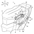
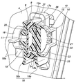
- positioning of the storage apparatus for vehicles which concerns on embodiment The perspective view which shows the side surface of the storage apparatus for vehicles which concerns on embodiment
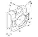
- the perspective view which shows the damper unit which concerns on embodiment The perspective view from the other direction which shows the damper unit which concerns on embodiment
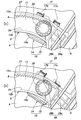
- the partial cross section side view showing the operation of the storage device for vehicles concerning an embodiment ((a) The posture of the damper unit in the closed state of a lid is shown. (B) The damper unit in the position where the lid opened slightly from the closed position Show posture)
- FIG. 1 shows a vehicle 2 in which a vehicle storage device 1 according to the embodiment is installed. Note that the vertical direction, the horizontal direction, and the front-rear direction in the description follow the direction of the vehicle 2.
- the storage device 1 is a glove box installed on the instrument panel 3 of the vehicle 2.
- the storage device 1 includes a storage device body 4 that is fixed to the instrument panel 3 and stores articles, and a lid 6 that opens and closes an opening 5 of the storage device body 4.
- FIG. 1 shows the lid 6 in a closed position with the opening 5 closed.
- the lid 6 is pivotally supported by the storage device main body 4 along an axis that is disposed on the lower end side and extends in the left-right direction.
- the lid 6 is releasably locked in the closed position by a lock mechanism using a known urging means.
- the lock is released, and the upper end side of the lid 6 is stored in the storage device by gravity or a force applied by the user. It tilts around the axis so as to be separated from the main body 4 and opens to the fully open position.
- the storage device 1 includes a lid arm 9 having a gear 8 and a damper unit 10 that meshes with the gear 8 of the lid arm 9 in order to attenuate the opening / closing speed of the lid 6.
- a lid arm 9 having a gear 8 and a damper unit 10 that meshes with the gear 8 of the lid arm 9 in order to attenuate the opening / closing speed of the lid 6.
- One set of the lid arm 9 and the damper unit 10 is preferably provided on the left and right sides of the lid 6. Since the left and right lid arms 9 and the damper unit 10 are substantially symmetrical with each other, a description will be given below of an example provided on the left side.
- the lid arm 9 is fixed to the left side of the lid 6 on the rear end side and at a position away from the tilting axis of the lid 6.
- the lid arm 9 extends in a shape along the tilting direction of the lid 6, that is, in an arc shape.
- the lid arm 9 is made of resin or the like, and has a flat main plate 11 whose main surface faces in the left-right direction, an upper rib 12a formed to extend to the left along the upper end and the lower end of the main plate 11, and And a lower rib 12b.
- a stopper 13 that defines the fully open position of the lid 6 is formed on the front end side of the lid arm 9 by extending upward from the upper rib 12 a and being locked to the storage device body 4.
- the damper unit 10 holds the lid arm 9 movably in the movement direction of the lid 6 and engages the damper holder 14 that engages with the storage device body 4 and the gear 8 of the lid arm 9. And a rotating damper 15 that is engaged with and held by the damper holder 14.
- the damper holder 14 is made of resin or the like, and includes a pair of sandwiching pieces 16 that sandwich the lid arm 9 from the left and right directions, and a connecting portion 17 that connects the upper ends of the pair of sandwiching pieces 16 to each other in the front-rear direction. It is generally U-shaped in a cross-sectional view orthogonal to.
- the connecting part 17 shown in the figure is divided into two parts, a first connecting part 17a on the rear and a second connecting part 17b on the front, but it may be divided into one or three or more.
- the connecting portion 17 may be provided on the lower end side of the pair of sandwiching pieces 16.
- the right holding piece 16a is formed with a cylindrical or columnar boss 20 which is received in a recess 19 formed by a wall 18 protruding leftward from the side surface of the storage device body 4. Since the boss 20 is loosely fitted into the recess 19 and is pivotally supported, the damper holder 14 is allowed to rotate about the left-right axis, and the boss 20 is displaced in a plane perpendicular to the left-right direction with respect to the storage device body 4. Is allowed within a predetermined range.
- the recess 19 is formed in the vicinity of the movement path of the gear 8 on the side surface of the storage device body 4.
- the concave portion 19 preferably has an oval shape in a side view, the major axis direction thereof is 90 ° or an angle close to 90 ° with respect to the moving direction of the lid arm 9, and the inner diameter of the concave portion 19 in the minor axis direction Coincides with the outer diameter of the boss 20, whereby the displacement of the boss 20 in the moving direction of the lid arm 9 relative to the storage device body 4 is restricted.
- the movement of the boss 20 in the direction perpendicular to the movement direction of the lid arm 9 relative to the storage device body 4 (normal direction of the movement direction of the lid arm 9 in the plane perpendicular to the left-right direction) is allowed within a predetermined range. Therefore, the angle can be changed in a range larger than 0 ° and smaller than 180 °.
- the wall 18 forming the recess 19 is provided with a reinforcing wall 18a extending in the front-rear direction or the moving direction of the lid arm 9 and downward.
- the left clamping piece 16b is provided with a fixing hole 22 for fitting and fixing the housing 21 of the rotary damper 15.
- the fixing hole 22 is formed so that the rotation axis of the rotary damper 15 is coaxial with the boss 20.
- the wall 23 that forms the fixing hole 22 extends in the left-right direction, and a part of the lower lower surface thereof constitutes a guide portion 25 that is in sliding contact with a smooth guided surface 24 formed on the upper surface of the lower rib 12b. ing.
- the guide portion 25 has an arc shape centered on the rotation axis of the rotary damper 15 in a side view, and the curvature radius thereof is smaller than the curvature radius of the guided surface 24. Rollable within a predetermined range. The rollable range is defined by the position where the connecting portion 17 is locked to the upper rib 12a.
- the rotation shaft of the rotary damper 15 is provided with a pinion 26 that meshes with the gear 8.
- the pinion 26 can rotate around the rotation axis with respect to the housing 21, and rotates by receiving resistance due to the viscosity of the oil in the housing 21.
- the pair of sandwiching pieces 16 sandwich the lower rib 12b of the lid arm 9, and the pinion 26 meshes with the gear 8 from below in the direction normal to the moving direction of the lid arm 9 in a plane orthogonal to the rotation axis. Since the guide portion 25 is in sliding contact with the guided surface from above, the lid arm 9 is held by the damper unit 10 so as to be movable only in the tilting direction of the lid 6 with respect to the damper unit 10.
- the distance from the rotation axis of the pinion 26 to the connecting portion 17 is slightly longer than the distance from the rotation axis of the pinion 26 to the smooth sliding contact surface 27 formed on the upper surface of the upper rib 12a. Due to the difference in distance and the fact that the guide portion 25 has an arc shape centered on the rotation axis of the rotary damper 15, the damper unit 10 is located with respect to the lid arm 9 about the rotation axis of the rotary damper 15. Can be tilted. This tilting range is defined by the sliding contact portion 28 formed in the connection portion 17 coming into contact with the sliding contact surface 27.
- the slidable contact portion 28 is formed so that the first slidable contact portion 28a constituting the rear edge of the lower surface of the first connecting portion 17a and the rear edge of the second connected portion 17b are slightly protruded downward. It consists of two parts 28b (see FIG. 6). When one of the first sliding contact portion 28 a and the second sliding contact portion 28 b is in contact with the sliding contact surface 27, the other is disposed so as to be separated from the sliding contact surface 27.
- FIG. 6A shows the periphery of the damper unit 10 when the lid 6 is in the closed position.
- the second sliding contact portion 28b slides on the sliding contact surface 27 as described later.
- the damper holder 14 is maintained in a state in which the second sliding contact portion 28b is in contact with the sliding contact surface 27 by the frictional force between the rotating shaft of the rotary damper 15 and the housing 21. Yes.
- the first slidable contact portion 28 a is in sliding contact with the slidable contact surface 27, so that the tilt of the damper holder 14 is restricted, so that the pinion 26 includes the housing 21 and the damper holder 14. Rotate against. Therefore, the lid 6 and the lid arm 9 are subjected to the damping force of the rotary damper 15.
- the lid 6 is opened to the fully open position where the stopper 13 is locked to the locking portion 29 of the storage device body 4 by gravity or a force applied by the user.
- the housing 21 is moved until the first sliding contact portion 28a is separated from the sliding contact surface 27 and the second sliding contact portion 28b is locked to the sliding contact surface 27. Since the damper holder 14 rotates following the pinion 26, the lid 6 and the lid arm 9 do not receive the damping force of the rotary damper 15. Therefore, in the initial stage of the closing operation, the user does not need to apply a large force, so that the operability is good.
- the boss 20 is loosened in the concave portion 19 even if the moving direction of the lid 6 does not completely coincide with the extending directions of the sliding contact surface 27, the gear 8, and the guided surface 24. Because of the fitting, the damper unit 10 holding the lid arm 9 moves in a plane orthogonal to the rotation axis, and the deviation is corrected. Therefore, it is possible to prevent unintended resistance between the lid arm 9 and the damper unit 10, tooth skipping, abnormal noise, and the like.
- the concave portion 19 has an oval shape in which the major axis direction is in a normal direction with respect to the moving direction of the lid arm 9 and the inner diameter in the minor axis direction matches the outer diameter of the boss 20 in a side view, Since the displacement in the moving direction of 9 is restricted and only the displacement in the direction perpendicular thereto is allowed, the structure of the recess 19 and the movable range of the damper unit 10 can be saved. Further, since the damper unit 10 holds the lid arm 9 and is loosely supported by the storage device body 4, the damper unit 10 is hardly affected by the rigidity of the lid arm 9.
- the lid arm 9 can be assembled to the storage device body 4 by inserting the boss 20 into the recess 19 in a state where the damper unit 10 is assembled to the lid arm 9, the assembly is easy.
- the connection part 17 which connects a pair of clamping pieces 16 is arrange
- the damper unit 10 is accommodated.
- the lid arm 9 can also be assembled by being inserted into the damper unit 10 from the front end side. This is because the stopper 13 protruding upward in the lid arm 9 can pass the free end side of the pair of clamping pieces 16.
- the present invention is not limited to the above-described embodiment, and can be widely modified. Only one sliding contact portion is provided, and at the initial stage of the opening operation and the closing operation, that one sliding contact portion is separated from a certain point of the sliding contact surface by tilting of the damper holder and then locked to another point on the sliding contact surface. In the subsequent opening operation and closing operation, the sliding contact surface may be slidably contacted. Further, the recess may be formed by recessing a part of the side wall of the storage device body, or may be changed to a hole.
- Vehicle storage device 4 Storage device body 6: Lid 8: Gear 9: Lid arm 14: Damper holder 15: Rotating damper 16: Nipping piece 17: Connection portion 19: Recess (receiving portion) 20: Boss 24: Guided surface 25: Guide portion 26: Pinion 27: Sliding contact surface 28: Sliding contact portion
Landscapes
- Engineering & Computer Science (AREA)
- Mechanical Engineering (AREA)
- Vehicle Step Arrangements And Article Storage (AREA)
Abstract
【課題】回転ダンパを有する車両用収納装置であって、リッドの移動方向とリッドアームに形成されたギヤの延在方向との間に生じ得るずれを許容する車両用収納装置を提供する。 【解決手段】車両用収納装置は、物品を収容する収納装置本体(4)に対してリッドが開閉する。リッド(6)の開閉は、ギヤ(8)を有するリッドアーム(9)と、ギヤに噛み合うピニオン(26)を有するダンパユニット(10)とによって減衰される。ダンパユニットのダンパホルダ(14)が、リッドアームを保持し、かつ収納装置本体に変位可能に支持される。そのため、リッドの移動方向とギヤの延在方向とずれは、ダンパユニット及びリッドアームが収納装置本体に対して変位することにより修正される。
Description
本開示は、車両用収納装置に関する。
車両用収納装置として、自動車のインストルメントパネルの助手席側下部に設置されるグローブボックスが挙げられる。グローブボックスとしては一体式とリッド式とが一般に採用されている。一体式のグローブボックスは、物品を収容するグローブボックス本体が回転してインストルメントパネルに設けられた開口を開閉する。リッド式のグローブボックスは、リッドが回転してインストルメントパネルに内装されるグローブボックス本体の開口を開閉する。グローブボックスの開閉に減衰装置を適用する場合、一体式のグローブボックスではエアダンパを用いることが一般的であるが、リッド式のグローブボックスでは、可動部分が一体式のグローブボックス比べて軽いため、比較的安価な回転式ダンパでも十分な減衰効果を得ることができる(例えば特許文献1)。
しかしながら、特許文献1に記載の構造では、製造誤差や組み付け誤差によって、リッドの移動方向と、リッドアームに形成されたギヤの延在方向とにずれが生じた場合、リッド開閉時に意図せぬ抵抗力や、歯とび、異音等が発生するおそれがあった。
上記問題を鑑み、本発明は、回転ダンパを有する車両用収納装置であって、リッドの移動方向と、リッドアームに形成されたギヤの延在方向と間に生じ得るずれを許容する車両用収納装置を提供することを目的とする。
本発明の少なくともいくつかの実施形態に係る車両用収納装置(1)は、車両(2)に固定され、開口(5)を有する収納装置本体(4)と、前記収納装置本体に対して、前記開口を閉鎖する閉鎖位置及び前記開口を開放する全開位置間を移動可能なリッド(6)と、前記リッドの移動方向に延在するように前記リッドに固定され、前記移動方向に沿うギヤ(8)を有するリッドアーム(9)と、前記リッドアームを前記移動方向に移動可能に保持するダンパホルダ(14)と、前記ダンパホルダに固定されたハウジング(21)、及び前記ハウジングから突出して前記ギヤに噛合するピニオン(26)を有する回転ダンパ(15)とを有し、前記ダンパホルダは、前記リッドアームを前記ピニオンの軸線方向から挟持する1対の挟持片(16)を有し、前記ダンパホルダが、前記ピニオンの軸線に対して直交する面内で、前記リッドアームの移動方向に対して角度をなす方向に変位可能に前記収納装置本体に支持されたことを特徴とする。
この構成によれば、製造誤差や組み付け誤差等によって、リッドの移動方向とギヤの延在方向とにずれが生じても、リッドアーム及びダンパホルダが、収納装置本体に対して変位してそのずれを修正し、リッド開閉時に意図せぬ抵抗力や、歯とび、異音等が発生することを防止できる。また、挟持片によってダンパホルダがリッドアームに取り付けられるため、組み付け性が良好である。
本発明の少なくともいくつかの実施形態は、上記構成において、前記収納装置本体による前記ダンパホルダの支持構造は、前記収納装置本体及び前記ダンパホルダの一方に設けられたボス(20)と、前記収納装置本体及び前記ダンパホルダの他方に設けられて前記ボスを受容する受容部(19)とを有し、前記受容部は、前記リッドアームの移動方向に沿った長さよりも前記移動方向に対する法線方向に沿った長さが長い。
この構成によれば、簡易な構造で、収納装置本体にダンパホルダを変位可能に支持させることができる。
本発明の少なくともいくつかの実施形態は、上記構成において、前記ダンパホルダの、前記リッドアームに対する、前記軸線に対して直交する面内における前記移動方向に対する法線方向に沿った変位が規制されたことを特徴とする。
この構成によれば、リッドの移動方向とギヤの延在方向との間のずれによって、リッドアームとダンパホルダとの間にずれが生じることを防止し、ギヤとピニオンとの間の適正な噛み合いを維持することができる。
本発明の少なくともいくつかの実施形態は、上記構成において、前記リッドアームは、互いに対向するように前記リッドアームの移動方向に沿って延在する1対のリブ(12a,12b)を有し、前記1対のリブの互いに対向する面の一方に、前記ギヤが形成され、前記1対の挟持片の一方が、前記回転ダンパを固定するとともに、前記1対のリブの互いに対向する面の他方に摺接するガイド部(25)を有する。
この構成によれば、簡易な構造で、前記リッドアームの前記ダンパホルダに対する法線方向に沿った変位を規制することができる。
本発明によれば、減衰機構を有する車両用収納装置において、リッドの移動方向と、リッドアームに形成されたギヤの延在方向との間に生じ得るずれを許容することができる。
以下、図面を参照して本発明の実施形態について説明する。図1は、実施形態に係る車両用収納装置1が設置された車両2を示す。なお、説明中の上下、左右及び前後の方向は、車両2の方向に従う。収納装置1は、車両2のインストルメントパネル3に設置されたグローブボックスである。収納装置1は、インストルメントパネル3に固定されて物品を収納する収納装置本体4と、収納装置本体4の開口5を開閉するリッド6とを備える。図1は、リッド6が開口5を閉鎖した閉鎖位置にある状態を示す。リッド6は、下端側に配置されて左右方向に延在する軸線に沿って収納装置本体4に軸支されている。
リッド6は、公知の付勢手段を用いたロック機構によって、閉鎖位置に解除可能にロックされている。使用者が、付勢手段の付勢力に逆らってリッド6に設けられたレバー7を引くことにより、ロックが解除され、重力又は使用者から加えられる力により、リッド6は、その上端側が収納装置本体4から離間するように軸線回りに傾動し、全開位置まで開く。
図2及び3に示すように、収納装置1は、リッド6の開閉速度を減衰させるため、ギヤ8を有するリッドアーム9と、リッドアーム9のギヤ8に噛み合うダンパユニット10とを備える。リッドアーム9及びダンパユニット10は、リッド6の左右に1組ずつ設けられることが好ましい。左右のリッドアーム9及びダンパユニット10は、概ね互いに左右対称の形状をなすため、以下、左方に設けられたものを例に説明する。
リッドアーム9は、後端側においてリッド6の左側部に、かつリッド6の傾動の軸線から離間した位置に固定されている。リッドアーム9は、リッド6の傾動の方向に沿う形状、すなわち、円弧状に延在する。リッドアーム9は、樹脂等を素材とし、主面が左右方向を向いた平板状の主板11と、主板11の上端及び下端に沿ってそれぞれ左側に延出するように形成された上リブ12a及び下リブ12bとを有する。リッドアーム9の前端側には、上リブ12aから上方に延出し、収納装置本体4に係止されることによって、リッド6の全開位置を規定するストッパ13が形成されている。
図4及び図5に示すように、ダンパユニット10は、リッドアーム9をリッド6の移動方向に移動可能に保持するとともに収納装置本体4に係合するダンパホルダ14と、リッドアーム9のギヤ8に噛み合うとともにダンパホルダ14に保持される回転ダンパ15とを備える。
ダンパホルダ14は、樹脂等を素材とし、左右方向からリッドアーム9を挟持する1対の挟持片16と、1対の挟持片16の上端側を互いに連結する接続部17とを有し、前後方向に直交する断面視で概ねコ字形状をなす。図示する接続部17は、後方の第1接続部17a及び前方の第2接続部17bの2つに分割されているが、1つであっても又は3つ以上に分割されていてもよい。なお、接続部17を1対の挟持片16の下端側に設けてもよい。
右方の挟持片16aには、収納装置本体4の側面から左方に突出する壁18によって形成された凹部19に受容される円筒又は円柱状のボス20が形成されている。ボス20は凹部19に緩く嵌合して軸支されるため、ダンパホルダ14の左右方向の軸線回りの回転が許容され、かつボス20の収納装置本体4に対する左右方向に直交する面内での変位が所定の範囲で許容される。凹部19は、収納装置本体4の側面におけるギヤ8の移動経路の近傍に形成される。凹部19は、側面視で、長円状を呈することが好ましく、その長軸方向がリッドアーム9の移動方向に対して90°又は90°に近い角度であり、凹部19の短軸方向の内径がボス20の外径に一致し、それにより、ボス20の収納装置本体4に対するリッドアーム9の移動方向への変位が規制される。なお、ボス20の収納装置本体4に対するリッドアーム9の移動方向に直交する方向(左右方向に直交する面内におけるリッドアーム9の移動方向の法線方向)への移動が所定の範囲で許容されればよいため、その角度は、0°より大きく180°より小さい範囲で変更可能である。また、凹部19を形成する壁18には、前後又はリッドアーム9の移動方向及び下方に延出する補強壁18aが設けられていることが好ましい。
左方の挟持片16bには、回転ダンパ15のハウジング21を嵌合して固定する固定穴22が設けられている。固定穴22は、回転ダンパ15の回転軸がボス20と同軸になるように形成されている。固定穴22を形成する壁23は左右方向に延在し、その下側の下面の一部は、下リブ12bの上面に形成された滑らかな被ガイド面24に摺接するガイド部25を構成している。ガイド部25は、側面視で回転ダンパ15の回転軸を中心とする円弧状を呈し、その曲率半径は、被ガイド面24の曲率半径よりも小さいため、ガイド部25は、被ガイド面24を所定の範囲で転動可能となっている。転動可能な範囲は、接続部17が上リブ12aに係止される位置によって規定される。
回転ダンパ15の回転軸には、ギヤ8と噛み合うピニオン26が設けられている。ピニオン26は、ハウジング21に対して回転軸回りに回転可能であり、ハウジング21内のオイルの粘性により抵抗を受けて回転する。リッドアーム9がダンパユニット10に対して、リッド6の傾動方向に沿って移動するとき、ギヤ8と噛み合ったピニオン26がハウジング21及びダンパホルダ14に対して回転すると、リッド6の開閉速度は減衰する。しかし、ハウジング21及びダンパホルダ14がピニオン26とともに回転すると、減衰力が発生せずリッド6の開閉速度は減衰しない。
左右方向においては、一対の挟持片16がリッドアーム9の下リブ12bを挟持し、回転軸に直交する平面におけるリッドアーム9の移動方向に対する法線方向では、ピニオン26がギヤ8に下方から噛み合い、ガイド部25が上方から被被ガイド面に摺接するため、リッドアーム9は、ダンパユニット10に対してリッド6の傾動方向にのみ移動可能となるようにダンパユニット10に保持されている。
ピニオン26の回転軸から接続部17までの距離は、ピニオン26の回転軸から上リブ12aの上面に形成された滑らかな摺接面27までの距離よりもわずかに長い。この距離の差があることと、ガイド部25が回転ダンパ15の回転軸を中心とする円弧形状であることとによって、ダンパユニット10は、回転ダンパ15の回転軸を中心としてリッドアーム9に対して傾動することができる。この傾動範囲は、接続部17に形成された摺接部28が摺接面27に当接することで規定される。摺接部28は、第1接続部17aの下面の後縁を構成する第1摺接部28aと、第2接続部17bの後縁においてわずかに下方突出するように形成された第2摺接部28b(図6参照)との2つからなる。第1摺接部28a及び第2摺接部28bは、一方が摺接面27に接しているときは、他方は摺接面27から離間するように配置されている。
次に、図3及び図6を参照して、実施形態に係る収納装置1のリッド6の開閉時の作用効果について説明する。
図6(a)は、リッド6が閉鎖位置にあるときのダンパユニット10の周辺を示す。リッド6を閉方向に動かすとき、後述のように第2摺接部28bが摺接面27を摺動する。リッド6が閉鎖位置に至った後も、回転ダンパ15の回転軸とハウジング21との摩擦力により、ダンパホルダ14は、第2摺接部28bが摺接面27に当接した状態に維持されている。
使用者が、レバー7(図1参照)を引いて、使用者が加える力又は重力によってリッド6がわずかに開方向に動くと図6(b)に示す状態になる。このとき、リッドアーム9がダンパユニット10に対してリッド6の移動方向に移動するため、ギヤ8に噛み合ったピニオン26が回転する。回転ダンパ15の回転軸とハウジング21との間の粘性抵抗によって、ハウジング21及びハウジング21を固定しているダンパホルダ14は、ピニオン26に従動して回転する。従って、ダンパユニット10は、第2摺接部28bが摺接面27から離間して、第1摺接部28aが摺接面27に当接するまで傾動する。この区間では、リッド6及びリッドアーム9は、回転ダンパ15の減衰力を受けない。
図6(b)に示す位置から全開位置までは、第1摺接部28aが摺接面27に摺接することによって、ダンパホルダ14の傾動が規制されるため、ピニオン26は、ハウジング21及びダンパホルダ14に対して回転する。そのため、リッド6及びリッドアーム9は、回転ダンパ15の減衰力をうける。
このようにリッド6の開動作の初期では減衰力が働かないため、使用者はリッド6を開く際に大きな力を加える必要がなく操作性が良好である。また、使用者がレバー7(図1参照)を離してもリッド6のロックが戻らない位置に、図6(b)の位置を設定しておけば、ロック解除不良になるリスクを軽減することができる。
その後リッド6は、重力又は使用者が加える力によって、ストッパ13が収納装置本体4の係止部29に係止する全開位置まで開く。リッド6を全開位置から閉鎖位置まで戻すときは、第1摺接部28aが摺接面27から離間して、第2摺接部28bが摺接面27に係止されるまでは、ハウジング21及びダンパホルダ14は、ピニオン26に従動して回転するため、リッド6及びリッドアーム9は、回転ダンパ15の減衰力を受けない。そのため、閉動作の初期においては、使用者は大きな力を加える必要がないため、操作性が良好である。
また、部材の製造誤差や組み付け誤差により、リッド6の移動方向と、摺接面27、ギヤ8及び被ガイド面24の延在方向とが完全に一致しなくとも、ボス20が凹部19に緩く嵌合しているため、リッドアーム9を保持するダンパユニット10が回転軸に直交する平面内で移動して、そのずれが修正される。よって、リッドアーム9及びダンパユニット10間の意図せぬ抵抗や、歯とび、異音の発生等を防止することができる。特に、凹部19が、側面視で、長軸方向がリッドアーム9の移動方向に対する法線方向を向き、短軸方向の内径がボス20の外径に一致する長円形状をなす場合、リッドアーム9の移動方向への変位が規制され、それに直交する方向の変位のみを許容すればよいため、凹部19の構造及びダンパユニット10の可動範囲を省スペースにすることができる。また、ダンパユニット10は、リッドアーム9を保持し、収納装置本体4に緩く支持されるため、リッドアーム9の剛性の影響を受け難い。
また、ダンパユニット10をリッドアーム9に組み付けた状態で、ボス20を凹部19に差し込むことによって、リッドアーム9を収納装置本体4に組み付けることができるため、組み付けが容易である。なお、1対の挟持片16を接続する接続部17を上方ではなく下方に配置し、摺接面27を下リブ12bの下面に形成するように変更した場合には、ダンパユニット10を収納装置本体4に組み付けた後、リッドアーム9を前端側からダンパユニット10に差し込んで組み付けることもできる。リッドアーム9において上方に突出したストッパ13が1対の挟持片16の遊端側を通過できるためである。
以上で具体的実施形態の説明を終えるが、本発明は上記実施形態に限定されることなく幅広く変形実施することができる。摺接部は1つのみ設け、その1つの摺接部が開操作及び閉操作初期段階では、ダンパホルダの傾動によって摺接面のある地点から離間した後に摺接面の別の地点に係止され、その後の開操作及び閉操作では摺接面を摺接するように構成してもよい。また、凹部は、収納装置本体の側壁の一部を凹ませて形成してもよく、孔に変更してもよい。
1:車両用収納装置
4:収納装置本体
6:リッド
8:ギヤ
9:リッドアーム
14:ダンパホルダ
15:回転ダンパ
16:挟持片
17:接続部
19:凹部(受容部)
20:ボス
24:被ガイド面
25:ガイド部
26:ピニオン
27:摺接面
28:摺接部
4:収納装置本体
6:リッド
8:ギヤ
9:リッドアーム
14:ダンパホルダ
15:回転ダンパ
16:挟持片
17:接続部
19:凹部(受容部)
20:ボス
24:被ガイド面
25:ガイド部
26:ピニオン
27:摺接面
28:摺接部
Claims (4)
- 車両に固定され、開口を有する収納装置本体と、
前記収納装置本体に対して、前記開口を閉鎖する閉鎖位置及び前記開口を開放する全開位置間を移動可能なリッドと、
前記リッドの移動方向に延在するように前記リッドに固定され、前記移動方向に沿うギヤを有するリッドアームと、
前記リッドアームを前記移動方向に移動可能に保持するダンパホルダと、
前記ダンパホルダに固定されたハウジング、及び前記ハウジングから突出して前記ギヤに噛合するピニオンを有する回転ダンパとを有し、
前記ダンパホルダは、前記リッドアームを前記ピニオンの軸線方向から挟持する1対の挟持片を有し、
前記ダンパホルダが、前記ピニオンの軸線に対して直交する面内で前記リッドアームの移動方向に対して角度をなす方向に変位可能に前記収納装置本体に支持されたことを特徴とする車両用収納装置。 - 前記収納装置本体による前記ダンパホルダの支持構造は、前記収納装置本体及び前記ダンパホルダの一方に設けられたボスと、前記収納装置本体及び前記ダンパホルダの他方に設けられて前記ボスを受容する受容部とを有し、
前記受容部は、前記リッドアームの移動方向に沿った長さよりも前記移動方向に対する法線方向に沿った長さが長いことを特徴とする請求項1に記載の車両用収納装置。 - 前記ダンパホルダの、前記リッドアームに対する、前記軸線に対して直交する面内における前記移動方向に対する法線方向に沿った変位が規制されたことを特徴とする請求項1又は2に記載の車両用収納装置。
- 前記リッドアームは、互いに対向するように前記リッドアームの移動方向に沿って延在する1対のリブを有し、
前記1対のリブの互いに対向する面の一方に、前記ギヤが形成され、
前記1対の挟持片の一方が、前記回転ダンパを固定するとともに、前記1対のリブの互いに対向する面の他方に摺接するガイド部を有することを特徴とする請求項3に記載の車両用収納装置。
Applications Claiming Priority (2)
| Application Number | Priority Date | Filing Date | Title |
|---|---|---|---|
| JP2016024246A JP6404247B2 (ja) | 2016-02-11 | 2016-02-11 | 車両用収納装置 |
| JP2016-024246 | 2016-02-11 |
Publications (1)
| Publication Number | Publication Date |
|---|---|
| WO2017138650A1 true WO2017138650A1 (ja) | 2017-08-17 |
Family
ID=59563821
Family Applications (1)
| Application Number | Title | Priority Date | Filing Date |
|---|---|---|---|
| PCT/JP2017/004975 Ceased WO2017138650A1 (ja) | 2016-02-11 | 2017-02-10 | 車両用収納装置 |
Country Status (2)
| Country | Link |
|---|---|
| JP (1) | JP6404247B2 (ja) |
| WO (1) | WO2017138650A1 (ja) |
Citations (4)
| Publication number | Priority date | Publication date | Assignee | Title |
|---|---|---|---|---|
| US5690194A (en) * | 1995-10-30 | 1997-11-25 | Illinois Tool Works Inc. | One-way pivoting gear damper |
| JPH10140926A (ja) * | 1996-11-07 | 1998-05-26 | Nifco Inc | ダンパー機構 |
| JP2005106230A (ja) * | 2003-10-01 | 2005-04-21 | Nifco Inc | ダンパ装置 |
| JP2012111365A (ja) * | 2010-11-25 | 2012-06-14 | Suzuki Motor Corp | 物品収納ボックス |
-
2016
- 2016-02-11 JP JP2016024246A patent/JP6404247B2/ja not_active Expired - Fee Related
-
2017
- 2017-02-10 WO PCT/JP2017/004975 patent/WO2017138650A1/ja not_active Ceased
Patent Citations (4)
| Publication number | Priority date | Publication date | Assignee | Title |
|---|---|---|---|---|
| US5690194A (en) * | 1995-10-30 | 1997-11-25 | Illinois Tool Works Inc. | One-way pivoting gear damper |
| JPH10140926A (ja) * | 1996-11-07 | 1998-05-26 | Nifco Inc | ダンパー機構 |
| JP2005106230A (ja) * | 2003-10-01 | 2005-04-21 | Nifco Inc | ダンパ装置 |
| JP2012111365A (ja) * | 2010-11-25 | 2012-06-14 | Suzuki Motor Corp | 物品収納ボックス |
Also Published As
| Publication number | Publication date |
|---|---|
| JP6404247B2 (ja) | 2018-10-10 |
| JP2017140957A (ja) | 2017-08-17 |
Similar Documents
| Publication | Publication Date | Title |
|---|---|---|
| KR101254841B1 (ko) | 양쪽 열림 리드장치 및 센터콘솔박스 | |
| JP2010036671A (ja) | 収納ボックスの開閉機構 | |
| JP5965166B2 (ja) | 収納装置 | |
| CN112055669B (zh) | 收纳箱 | |
| JP5396067B2 (ja) | トレイ装置 | |
| US20100154309A1 (en) | Door opening and closing structure and door opening and closing system | |
| WO2018047684A1 (ja) | ロック装置 | |
| WO2014103672A1 (ja) | ロック部構造 | |
| JP5788253B2 (ja) | ロック装置 | |
| WO2017056625A1 (ja) | 車両用アウトサイドハンドル装置 | |
| JP2025145520A (ja) | 車両用両開き収容装置 | |
| JP6404247B2 (ja) | 車両用収納装置 | |
| JP6445987B2 (ja) | 車両用収納装置 | |
| WO2010103980A1 (ja) | 移動体の駆動装置 | |
| KR101575043B1 (ko) | 글로브박스용 개폐장치 | |
| JP2021134816A (ja) | ボーデンケーブル及びこれを使用した回転部材の連結装置並びに自動車用ドアロックの連結装置 | |
| KR101877668B1 (ko) | 차량용 수납장치 | |
| JP5630382B2 (ja) | サイドロック装置 | |
| JP6391226B2 (ja) | ロック装置 | |
| JP4609292B2 (ja) | 車両用収納ボックス | |
| JP6442335B2 (ja) | ロック装置 | |
| JP6658468B2 (ja) | フューエルリッド構造 | |
| JP6727741B2 (ja) | ダンパー装置 | |
| JP5016350B2 (ja) | 車両用物入装置 | |
| JP5317773B2 (ja) | 容器ホルダ装置 |
Legal Events
| Date | Code | Title | Description |
|---|---|---|---|
| 121 | Ep: the epo has been informed by wipo that ep was designated in this application |
Ref document number: 17750371 Country of ref document: EP Kind code of ref document: A1 |
|
| NENP | Non-entry into the national phase |
Ref country code: DE |
|
| 122 | Ep: pct application non-entry in european phase |
Ref document number: 17750371 Country of ref document: EP Kind code of ref document: A1 |