WO2017138444A1 - 作業車両 - Google Patents
作業車両 Download PDFInfo
- Publication number
- WO2017138444A1 WO2017138444A1 PCT/JP2017/003897 JP2017003897W WO2017138444A1 WO 2017138444 A1 WO2017138444 A1 WO 2017138444A1 JP 2017003897 W JP2017003897 W JP 2017003897W WO 2017138444 A1 WO2017138444 A1 WO 2017138444A1
- Authority
- WO
- WIPO (PCT)
- Prior art keywords
- turning
- traveling
- straight
- output
- transmission path
- Prior art date
Links
Images


Classifications
-
- B—PERFORMING OPERATIONS; TRANSPORTING
- B62—LAND VEHICLES FOR TRAVELLING OTHERWISE THAN ON RAILS
- B62D—MOTOR VEHICLES; TRAILERS
- B62D11/00—Steering non-deflectable wheels; Steering endless tracks or the like
- B62D11/001—Steering non-deflectable wheels; Steering endless tracks or the like control systems
- B62D11/003—Electric or electronic control systems
-
- B—PERFORMING OPERATIONS; TRANSPORTING
- B62—LAND VEHICLES FOR TRAVELLING OTHERWISE THAN ON RAILS
- B62D—MOTOR VEHICLES; TRAILERS
- B62D11/00—Steering non-deflectable wheels; Steering endless tracks or the like
- B62D11/02—Steering non-deflectable wheels; Steering endless tracks or the like by differentially driving ground-engaging elements on opposite vehicle sides
- B62D11/06—Steering non-deflectable wheels; Steering endless tracks or the like by differentially driving ground-engaging elements on opposite vehicle sides by means of a single main power source
- B62D11/08—Steering non-deflectable wheels; Steering endless tracks or the like by differentially driving ground-engaging elements on opposite vehicle sides by means of a single main power source using brakes or clutches as main steering-effecting means
-
- B—PERFORMING OPERATIONS; TRANSPORTING
- B62—LAND VEHICLES FOR TRAVELLING OTHERWISE THAN ON RAILS
- B62D—MOTOR VEHICLES; TRAILERS
- B62D11/00—Steering non-deflectable wheels; Steering endless tracks or the like
- B62D11/02—Steering non-deflectable wheels; Steering endless tracks or the like by differentially driving ground-engaging elements on opposite vehicle sides
- B62D11/06—Steering non-deflectable wheels; Steering endless tracks or the like by differentially driving ground-engaging elements on opposite vehicle sides by means of a single main power source
- B62D11/10—Steering non-deflectable wheels; Steering endless tracks or the like by differentially driving ground-engaging elements on opposite vehicle sides by means of a single main power source using gearings with differential power outputs on opposite sides, e.g. twin-differential or epicyclic gears
- B62D11/14—Steering non-deflectable wheels; Steering endless tracks or the like by differentially driving ground-engaging elements on opposite vehicle sides by means of a single main power source using gearings with differential power outputs on opposite sides, e.g. twin-differential or epicyclic gears differential power outputs being effected by additional power supply to one side, e.g. power originating from secondary power source
- B62D11/18—Steering non-deflectable wheels; Steering endless tracks or the like by differentially driving ground-engaging elements on opposite vehicle sides by means of a single main power source using gearings with differential power outputs on opposite sides, e.g. twin-differential or epicyclic gears differential power outputs being effected by additional power supply to one side, e.g. power originating from secondary power source the additional power supply being supplied hydraulically
- B62D11/183—Control systems therefor
-
- E—FIXED CONSTRUCTIONS
- E02—HYDRAULIC ENGINEERING; FOUNDATIONS; SOIL SHIFTING
- E02F—DREDGING; SOIL-SHIFTING
- E02F3/00—Dredgers; Soil-shifting machines
- E02F3/04—Dredgers; Soil-shifting machines mechanically-driven
- E02F3/76—Graders, bulldozers, or the like with scraper plates or ploughshare-like elements; Levelling scarifying devices
- E02F3/80—Component parts
- E02F3/84—Drives or control devices therefor, e.g. hydraulic drive systems
- E02F3/841—Devices for controlling and guiding the whole machine, e.g. by feeler elements and reference lines placed exteriorly of the machine
-
- E—FIXED CONSTRUCTIONS
- E02—HYDRAULIC ENGINEERING; FOUNDATIONS; SOIL SHIFTING
- E02F—DREDGING; SOIL-SHIFTING
- E02F9/00—Component parts of dredgers or soil-shifting machines, not restricted to one of the kinds covered by groups E02F3/00 - E02F7/00
- E02F9/20—Drives; Control devices
- E02F9/2025—Particular purposes of control systems not otherwise provided for
-
- B—PERFORMING OPERATIONS; TRANSPORTING
- B60—VEHICLES IN GENERAL
- B60Y—INDEXING SCHEME RELATING TO ASPECTS CROSS-CUTTING VEHICLE TECHNOLOGY
- B60Y2200/00—Type of vehicle
- B60Y2200/20—Off-Road Vehicles
- B60Y2200/22—Agricultural vehicles
- B60Y2200/221—Tractors
-
- B—PERFORMING OPERATIONS; TRANSPORTING
- B62—LAND VEHICLES FOR TRAVELLING OTHERWISE THAN ON RAILS
- B62D—MOTOR VEHICLES; TRAILERS
- B62D55/00—Endless track vehicles
-
- E—FIXED CONSTRUCTIONS
- E02—HYDRAULIC ENGINEERING; FOUNDATIONS; SOIL SHIFTING
- E02F—DREDGING; SOIL-SHIFTING
- E02F3/00—Dredgers; Soil-shifting machines
- E02F3/04—Dredgers; Soil-shifting machines mechanically-driven
- E02F3/76—Graders, bulldozers, or the like with scraper plates or ploughshare-like elements; Levelling scarifying devices
- E02F3/7609—Scraper blade mounted forwardly of the tractor on a pair of pivoting arms which are linked to the sides of the tractor, e.g. bulldozers
-
- E—FIXED CONSTRUCTIONS
- E02—HYDRAULIC ENGINEERING; FOUNDATIONS; SOIL SHIFTING
- E02F—DREDGING; SOIL-SHIFTING
- E02F9/00—Component parts of dredgers or soil-shifting machines, not restricted to one of the kinds covered by groups E02F3/00 - E02F7/00
- E02F9/02—Travelling-gear, e.g. associated with slewing gears
-
- E—FIXED CONSTRUCTIONS
- E02—HYDRAULIC ENGINEERING; FOUNDATIONS; SOIL SHIFTING
- E02F—DREDGING; SOIL-SHIFTING
- E02F9/00—Component parts of dredgers or soil-shifting machines, not restricted to one of the kinds covered by groups E02F3/00 - E02F7/00
- E02F9/16—Cabins, platforms, or the like, for drivers
Definitions
- the present invention relates to a work vehicle such as a farm work machine such as a tractor or a combiner or a special work machine such as a crane truck or a back fore.
- a work vehicle such as a farm work machine such as a tractor or a combiner or a special work machine such as a crane truck or a back fore.
- a work vehicle such as a farm vehicle such as a tractor or a combiner or a construction machine such as a crawler crane has been provided with two hydraulic continuously variable transmissions (HST) to which power from an engine is transmitted.
- HST continuously variable transmissions
- Some types of continuously variable transmissions output straight power and turning power based on engine output.
- the applicant of the present application previously proposed a work vehicle in Patent Document 1 that can turn by combining the straight power and the turning power output from each of the two hydraulic continuously variable transmissions with the left and right planetary gear mechanisms. ing.
- HMT hydraulic mechanical transmission
- the applicant of the present application has previously made a series-type (in-line type) hydraulic mechanical transmission in which the hydraulic pump and the hydraulic motor are arranged in series so that the input shaft of the hydraulic pump and the output shaft of the hydraulic motor are positioned concentrically. Is proposed in Patent Document 2.
- an output shaft is fitted on an input shaft to which power is transmitted from an engine so as to be relatively rotatable. Further, a hydraulic pump, a cylinder block, and a hydraulic motor are fitted on the input shaft. The cylinder block alone serves as both a hydraulic pump and a hydraulic motor, and power is transmitted from the hydraulic motor to the output shaft. For this reason, unlike a general hydraulic mechanical transmission, an in-line type hydraulic mechanical transmission can output a combination of hydraulic shift power and engine power without interposing a planetary gear mechanism. It has the advantage that transmission efficiency can be obtained.
- JP 2002-059753 A Japanese Patent Laying-Open No. 2005-083497
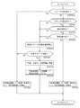
- the controller that controls the traveling operation needs to control the swash plate angles of the two hydraulic continuously variable transmissions by integrating the signals from the operation tools for main shift, forward / reverse, and turning.
- the control flow must be executed by the controller. For this reason, the controller has a high calculation load in the control flow of the traveling operation, which may cause the operator to feel uncomfortable.
- This invention makes it a technical subject to provide the work vehicle which improved after examining the above present conditions.
- a work vehicle includes an engine mounted on a traveling machine body, a straight traveling system transmission path having a first continuously variable transmission, and a turning system transmission path having a second continuously variable transmission, wherein the straight traveling system transmission path
- a control unit that controls the output of the straight traveling system transmission path and the output of the turning system transmission path in an interlocking manner
- a power transmission mechanism that interrupts power transmission from the linear transmission path, and the control unit, when power transmission from the linear transmission path is interrupted by the power transmission mechanism, By limiting the output of the turning system transmission path, the reversing operation of the left and right traveling parts is prohibited.
- the work vehicle includes a speed change operation tool that specifies an output of the straight travel system transmission path and a detector that detects an output of the straight travel system transmission path, and the control unit receives a command from the speed change operation tool.
- the output of the turning system transmission path is set by alternatively selecting the value and the actual measurement value from the detector, and the power transmission from the straight transmission system transmission path is interrupted by the power transmission mechanism. In this case, the output of the turning transmission path may be set based on the actual measurement value from the detector.
- the control unit when the power transmission mechanism cuts off power transmission from the linear transmission path, the control unit is configured such that one traveling direction of the traveling unit is opposite to the traveling direction of the traveling machine body.
- the output of the turning system transmission path may be limited by limiting the coefficient by which the actual measurement value from the detector is multiplied.
- the work vehicle includes a steering handle that can be rotated, and the control unit has a steering angle of a predetermined angle when power transmission from the linear transmission path is interrupted by the power transmission mechanism.
- the output of the turning transmission path may be limited by limiting the coefficient by which the actual measurement value from the detector is multiplied.
- control unit includes a first control unit that controls an output of the straight traveling system transmission path, and a second control unit that controls an output of the turning system transmission path.
- the output of the turning transmission path may be set by the second control section receiving the output of the straight traveling transmission path set by the control section.
- the power transmission mechanism cuts off the power transmission from the straight traveling system transmission path
- the reverse traveling operation by the left and right traveling parts is prohibited, so that the straight traveling system transmission path is operating with inertia.
- the differential output from the swivel transmission path is limited. Therefore, even when the braking action is not acting on the output side of the straight traveling system transmission path, it is possible to always set the output of the turning system transmission path optimal for the traveling state of the traveling machine body.
- the traveling machine body is prevented from continuously performing a pivotal turn, and the reaction force such as frictional force from the ground against the traveling unit is prevented. You can drive safely by applying a braking action by force.
- the present invention it is possible to select the command value from the shifting operation tool and the actual measurement value from the detector to set the output of the turning system transmission path, so that the traveling state of the traveling machine body is set.
- the output of the optimal turning system transmission path can always be set. Therefore, the operator can stably maneuver even when the traveling vehicle body turns, thereby improving the maneuverability and executing a stable driving operation.
- the output of the turning system transmission path is set with an actual measurement value when the power transmission mechanism is cut off, even if the command value based on the shifting operation tool and the actual measurement value are greatly different, It is possible to turn at a turning center and a turning radius according to the traveling state of the traveling machine body. Therefore, the operator can operate the traveling body without a sense of incongruity, and the smooth maneuverability can be contributed to the operator. In addition, the operator can stably maneuver even when the traveling machine body turns, thereby improving the maneuverability and executing a stable driving operation.
- the traveling aircraft by determining the speed ratio of the left and right traveling parts when turning based on the turning angle of the steering handle, the traveling aircraft can be turned according to the operation amount of the steering handle, It can contribute to the improvement of sex.
- the output of the straight traveling system transmission path and the output of the turning system transmission path are linked, not only the vehicle speed at the time of turning becomes close to the operator's sense of steering, but also the behavior of the traveling machine body can be stabilized.
- control can be performed in a distributed manner by each of the first and second control units, it is possible to reduce the amount of calculation of each, and to execute travel control with good responsiveness.
- the output from the first control unit is received and the output of the turning system transmission path is set, so that the running control is executed more smoothly without complicating the calculation. .
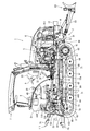
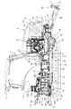
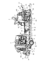
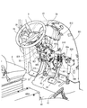
- FIGS. 1 to 6 the traveling machine body 2 of the tractor 1 is supported by a pair of left and right traveling crawlers 3 as traveling portions.
- a diesel engine 5 (hereinafter simply referred to as an engine) is mounted on the front of the traveling machine body 2, and the traveling crawler 3 is driven by the engine 5 so that the tractor 1 travels forward and backward.
- the engine 5 is covered with a bonnet 6.
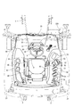
- a cabin 7 is installed on the upper surface of the traveling machine body 2. Inside the cabin 7, a steering seat 8 and a steering handle 9 for steering the traveling crawler 3 are arranged. Steps 10 on which the operator gets on and off are provided on the left and right outer sides of the cabin 7.
- a fuel tank 11 for supplying fuel to the engine 5 is provided below the left and right sides of the cabin 7.
- the fuel tank 11 is covered with left and right rear fenders 21.
- a battery 817 that supplies power to the front of the fuel tank 11 is provided on the left side of the cabin 7, and is covered with the left rear fender 21 together with the fuel tank 11.
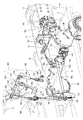
- the traveling machine body 2 includes an engine frame 14 having a front bumper 12 and a turning mission case (drive axle) 13 and left and right machine frame 15 detachably fixed to a rear portion of the engine frame 14.
- the axle 16 is rotatably projected outwardly from the left and right ends of the turning mission case 13, and axle cases 90 covering the axle 16 are provided on both the left and right sides of the turning mission case 13.
- Drive sprockets 62 are attached to the left and right ends of the turning mission case 13 via axles 16.
- the rear portion of the body frame 15 is connected to a straight transmission case 17 for appropriately shifting the rotational power from the engine 5 and transmitting it to the drive sprocket 62.
- left and right track frames 61 are arranged on the lower surface side of the traveling machine body 2.
- the track frame 61 extends in the front-rear direction and is provided in a pair of left and right sides, and is positioned on both outer sides of the engine frame 14 and the body frame 15.
- the left and right track frames 61 are connected to the engine frame 14 and the body frame 15 by a lower frame 67 extending in the left-right direction.
- the front ends of the left and right track frames 61 are connected to axle cases 90 provided on both left and right sides of the turning mission case 13.
- a step 10a on which the operator gets on and off is provided on the outside of each of the left and right track frames 61.
- the left and right central part of the lower frame 67 is fixed to the rear side surface of the engine frame 14 via a connection bracket 72.
- the left and right ends of a beam frame 68 extending in the left-right direction are connected to the middle part of the left and right track frames 61 in the front-rear direction.
- the center of the beam frame 68 is connected to the center of the lower frame 67 via a reinforcing frame 70 provided in the front-rear direction.
- Rear beams 73 projecting inward at the rear of the left and right track frames 61 are connected to rear housings 74 fixed to the left and right side surfaces of the straight traveling mission case 17 so that the rear part of the track frame 61 is connected to the left and right side surfaces of the transmission case 17. Fix it.
- the track frame 61 includes a drive sprocket 62 that transmits the power of the engine 5 to the traveling crawler 3, a tension roller 63 that maintains the tension of the traveling crawler 3, and a plurality of track rollers that hold the ground side of the traveling crawler 3 in a grounded state. 64 and an intermediate roller 65 that holds the non-grounding side of the traveling crawler 3.
- the driving sprocket 62 supports the front side of the traveling crawler 3
- the tension roller 63 supports the rear side of the traveling crawler 3
- the track roller 64 supports the grounding side of the traveling crawler 3
- the intermediate roller 65 supports the non-traveling crawler 3. Support the ground side.
- the tension roller 63 is rotatably supported by a rear end of a tension frame 69 configured to be extendable and retractable rearward from the rear end of the track frame 61.
- the track roller 64 is rotatably supported on the front and back of an equalizer frame 71 supported on the lower part of the track frame 61 so as to be swingable back and forth.
- a front dozer 80 can be mounted on the front of the tractor 1.
- a pair of left and right dozer brackets 81 are fixed to the front side surface of the engine frame 14, the axle case 90, and the lower frame 67, and a U-shaped (U-shaped) support arm 83 of the front dozer 80 in the plan view is
- the dozer bracket 81 is pivotally supported so as to be detachable on the outside (machine outside).
- the left and right dozer brackets 81 have a front end inside (machine inside) connected to the side surfaces of the left and right engine frames 14, a rear end lower side connected to the upper surface of a middle part of the lower frame 67, and a midway part in the middle of the axle case 90. It is connected so that it can be held up and down.
- the dozer bracket 81 can be secured to the three bodies of the engine frame 14, the axle case 90, and the lower frame 67, thereby ensuring the strength to withstand heavy work by the front dozer 80.
- a hydraulic lifting mechanism 22 that lifts and lowers a ground working machine (not shown) such as a rotary tiller is detachably attached to the rear portion of the straight traveling case 17.
- the ground work machine is connected to the rear part of the straight traveling transmission case 17 via a three-point link mechanism 111 including a pair of left and right lower links 23 and a top link 24.
- a PTO shaft 25 for transmitting a PTO driving force to a working machine such as a rotary tiller is provided on the rear side surface of the straight traveling case 17 so as to protrude rearward.
- a flywheel 26 is attached to the rear end of the output shaft (piston rod) 5a of the engine 5 projecting rearward from the rear side surface of the engine 5.
- a main shaft 27 projecting rearward from the flywheel 26 and an input counter shaft 28 projecting forward from the front side of the straight traveling mission case 17 are connected via a power transmission shaft 29 having universal shaft joints at both ends.
- the straight output shaft 30 that protrudes forward from the lower front portion of the straight transmission case 17 has a linear input counter that protrudes backward from the turning mission case 13 via a power transmission shaft 31 having universal joints at both ends.
- the shaft 508 is connected.
- the turning input counter shaft 712 is connected.
- the hydraulic lifting mechanism 22 is provided with lift fulcrums on the left and right hydraulic lift cylinders 117 that are controlled by operation of the working portion position dial 51 and the upper lid of the transmission case 17 for straight traveling.
- Left and right lift arms 120 that pivotally support the base end side through a shaft so as to be rotatable, and left and right lift rods 121 that connect the left and right lift arms 120 to the left and right lower links 23 are provided.
- a part of the right lift rod 121 is formed by a horizontal cylinder 122 for hydraulic control, and the length of the right lift rod 121 is configured to be adjustable by the horizontal cylinder 122.
- the piston of the horizontal cylinder 122 is expanded and contracted to change the length of the right lift rod 121.
- the angle is configured to change.
- a steering column 32 is disposed in front of the control seat 8 in the cabin 7.
- the steering column 32 is erected in a state of being embedded in the back side of the dashboard 33 disposed on the front side inside the cabin 7.
- a steering handle 9 having a substantially round shape in plan view is attached to the upper end side of the handle shaft 921 that protrudes upward from the upper surface of the steering column 32.
- a steering angle (steering angle) detection mechanism 880 having a steering angle sensor 821 for detecting the steering angle of the steering handle 9 is connected to the lower end of the handle shaft 921 in the steering column 32.
- a brake pedal 35 for braking the traveling machine body 2 is disposed on the right side of the steering column 32.
- the forward / reverse switching lever 36 (reverser lever) for switching the traveling direction of the traveling machine body 2 between forward and reverse, and the hydraulic clutches 537, 539, and 541 for power transmission are shut off.
- a clutch pedal 37 for operation is provided.
- a parking brake lever 43 for holding the brake pedal 35 in the depressed position is disposed on the rear side of the steering column 32.
- An erroneous operation preventing body 38 (reverser guard) extending along the forward / reverse switching lever 36 is disposed on the left side of the steering column 32 and below the forward / reverse switching lever 36.
- an erroneous operation prevention body 38 as a contact preventer below the forward / reverse switching lever 36, the operator is prevented from inadvertently contacting the forward / reverse switching lever 36 when getting on and off the tractor 1.
- An operation display panel 39 incorporating a liquid crystal panel is provided on the upper rear side of the dashboard 33.
- Accelerator pedal 41 for controlling the rotational speed of the engine 5 or the vehicle speed is disposed on the right side of the steering column 32 on the floor plate 40 in front of the control seat 8 in the cabin 7. Note that substantially the entire top surface of the floor plate 40 is formed as a flat surface.
- Side columns 42 are arranged on both the left and right sides of the control seat 8. Between the control seat 8 and the left side column 42, an ultra-low speed lever 44 (creep lever) for forcibly and greatly reducing the traveling speed (vehicle speed) of the tractor 1 and a traveling sub-shift in the straight traveling mission case 17 are provided.
- An auxiliary transmission lever 45 for switching the output range of the gear mechanism and a PTO transmission lever 46 for switching the drive speed of the PTO shaft 25 are arranged.
- an armrest 49 for placing the arm and elbow of the operator seated on the control seat 8 is provided.
- the armrest 49 is configured separately from the control seat 8 and has a main transmission lever 50 that increases and decreases the traveling speed of the tractor 1 and a dial type that manually changes and adjusts the height position of a ground working machine such as a rotary tiller.
- Working part position dial 51 (elevating dial).
- the armrest 49 is configured to be able to be turned up and rotated in a plurality of stages with the rear end lower part as a fulcrum.
- the vehicle speed of the traveling machine body 2 increases when the main transmission lever 50 is tilted forward, while the vehicle speed of the traveling machine body 2 decreases when the main transmission lever 50 is tilted backward.
- the armrest 49 includes a potentiometer (variable resistor) type main transmission sensor 822 (see FIG. 13) that detects the forward / backward tilt of the main transmission lever 50.
- the right side column 42 has, in order from the front side, an operation monitor 55 having a touch panel function and capable of commanding each part of the tractor 1, a throttle lever 52 for setting and maintaining the rotational speed of the engine 5, and the PTO shaft 25.
- a plurality of hydraulic control levers for switching between a PTO clutch switch 53 for intermittently transmitting power to a working machine such as a rotary tiller and a hydraulic external take-off valve 430 disposed on the upper surface side of the straight traveling mission case 17 54 (SCV lever) and a single-acting switch 56 for switching the actuating double-acting valve mechanism 431 disposed on the front surface of the rear housing 74.
- the hydraulic external take-off valve 430 is for controlling supply of hydraulic oil to hydraulic equipment of another work machine such as a front loader retrofitted to the tractor 1.
- the double-acting valve mechanism 431 is for operating the hydraulic lift cylinder 117 in a double-acting manner by operating together with the elevating valve mechanism 652 disposed on the upper surface side of the straight traveling mission case 17.
- a brake pedal support bracket 916 that supports the brake pedal shaft 755 is fixed to the back surface of the board support plate (air cut plate) 901 (the control seat 8 side).
- the base end boss portion 35a of the brake pedal 35 is fitted on the brake pedal shaft 755, and the base end boss portion 35a of the brake pedal 35 is connected so as to rotate integrally with the brake pedal shaft 755.
- the pedal shaft arm 756 protruding forward is fixed to both ends of the brake pedal shaft 755, and the pedal shaft arm 756 rotates together with the brake pedal shaft 755.
- the base end boss portion of the clutch pedal 37 is also fitted to the brake pedal shaft 755 so as to be rotatable.
- a clutch position sensor 829 (see FIG. 13) and a brake position sensor 828 are fixed to the left and right ends of the brake pedal shaft 755, respectively.
- a brake switch 851 is disposed at a position facing the pedal arm 35b of the brake pedal 35, and a clutch switch 852 (see FIG. 13) is disposed at a position facing the pedal arm 37b of the clutch pedal 37.
- a pair of left and right brake operation shafts 757 are supported on the lower left and right sides of the board support plate (air cut plate) 901.
- a link boss body 758 connected to the brake arm 752 of the brake mechanism 751 in the turning mission case 13 is rotatably fitted to the left brake operation shaft 757.
- a link arm 759 projecting from the outer peripheral surface of the link boss body 758 has a two-stage expansion / contraction that makes the braking operation of the brake mechanism 751 stepwise and the lower end of a vertically long link rod 762 connected to the left pedal shaft arm 756.
- the upper end of the link body 763 is connected.
- the lower end of the two-stage telescopic link body 763 is connected to the tip of the link arm 767 at the rear end of the brake rod 766.
- the brake rod 766 is supported by link support brackets 764 and 765 fixed to the engine frame 14 and extends in the front-rear direction.
- the link arm 768 at the front end of the brake rod 766 is connected to the brake arm 752 of the brake mechanism 751 in the turning mission case 13 via the connecting plate 753.
- the left end of the brake pedal shaft 755 is connected to the brake arm 752 of the brake mechanism 751 via the link rod 762, the two-stage telescopic link body 763, and the brake rod 766. Therefore, as the brake pedal shaft 755 rotates as the brake pedal 35 is depressed, the brake arm 752 can be rotated, and the braking operation by the brake mechanism 751 can be executed. At this time, when the two-stage telescopic link body 763 acts, the amount of stepping for sudden braking is larger (the brake mechanism 751) than when the amount of stepping for adjusting the traveling speed is small (the play area of the brake mechanism 751). The braking force applied to the brake pedal 35 is increased in the braking region).
- a link boss body 760 having a link arm 761 is rotatably fitted on the right brake operation shaft 757.
- the upper end of a two-stage telescopic link body 769 for stepping on the brake pedal 35 is connected to the right pedal shaft arm 756, and the link arm 761 projecting from the outer peripheral surface of the link boss body 760 has two stages.
- the lower end of the telescopic link body 769 is connected.
- the parking brake lever 43 is connected to one end of the locking member 771 via the parking brake arm 770.
- the locking member 771 having an arcuate side view is fixed to the brake pedal support bracket 916.
- a locking plate 775 that is engaged with the locking claw of the locking member 771 is provided on the left side surface of the pedal arm 35b of the brake pedal 35.
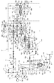
- the internal structure of the straight traveling mission case 17 and the turning mission case 13 and the power transmission system of the tractor 1 will be described with reference mainly to FIG. 4 to FIG. 6, FIG. 10, and FIG.
- a hydraulic mechanical continuously variable transmission 500 for straight traveling there are a hydraulic mechanical continuously variable transmission 500 for straight traveling, a mechanical creep transmission gear mechanism 502 for shifting rotational power via a forward / reverse switching mechanism 501, which will be described later, and a traveling auxiliary gear.
- a transmission gear mechanism 503 is disposed.
- a forward / reverse switching mechanism 501 that switches the rotational power from the hydraulic mechanical continuously variable transmission 500 in the forward or reverse direction is disposed in the intermediate chamber of the transmission case 17 for straight travel.
- a PTO transmission mechanism 505 that appropriately changes the rotational power from the engine 5 and transmits it to the PTO shaft 25 is disposed in the rear chamber of the straight traveling mission case 17.
- the creep transmission gear mechanism 502 and the traveling auxiliary transmission gear mechanism 503 correspond to a traveling transmission gear mechanism that multi-shifts the transmission output via the forward / reverse switching mechanism 501.
- a pump case 480 accommodating a working machine hydraulic pump 481 driven by the rotational power of the engine 5 and a traveling hydraulic pump 482 is attached to the front part of the right outer surface of the straight traveling case 17.
- the flywheel 26 is directly connected to the output shaft 5a of the engine 5 protruding rearward from the rear side of the engine 5.
- An input counter shaft 28 projecting forward from the front side of the straight traveling mission case 17 is connected to a main driving shaft 27 projecting rearward from the flywheel 26 through a power transmission shaft 29 having universal joints at both ends.
- the rotational power of the engine 5 is transmitted to the input counter shaft 28 of the straight traveling mission case 17 via the main driving shaft 27 and the power transmission shaft 29, and the hydraulic mechanical continuously variable transmission 500 and the creep transmission gear mechanism 502 or the traveling auxiliary gear
- the speed is appropriately changed by the transmission gear mechanism 503.
- the shifting power via the creep transmission gear mechanism 502 or the traveling auxiliary transmission gear mechanism 503 is transferred to the gear mechanism in the turning mission case 13 via the linear output shaft 30, the power transmission shaft 31, and the linear input counter shaft 508. Communicated.
- a main transmission output shaft 512 is concentrically disposed on a main transmission input shaft 511, and a hydraulic pump unit 521, a cylinder block, and a hydraulic motor unit 522 are arranged in series.
- a main transmission input gear 513 is fitted on the rear end side of the input counter shaft 28 so as not to be relatively rotatable.
- An input transmission gear 514 that is always meshed with the main transmission input gear 513 is fixed to the rear end side of the main transmission input shaft 511.
- the rotational power of the input counter shaft 28 is transmitted to the hydraulic mechanical continuously variable transmission 500 via the main transmission input gear 513, the input transmission gear 514, and the main transmission input shaft 511.
- a main transmission high-speed gear 516, a main transmission reverse gear 517, and a main transmission low-speed gear 515 are fitted on the main transmission output shaft 512 so as not to rotate relative to each other for traveling output.
- the input side of the main transmission input shaft 511 and the output side of the main transmission output shaft 512 are located on the same side (both rear as viewed from the hydraulic mechanical continuously variable transmission 500).
- the hydraulic mechanical continuously variable transmission 500 includes a variable displacement hydraulic pump unit 521 and a constant displacement hydraulic motor unit 522 that is operated by high-pressure hydraulic oil discharged from the hydraulic pump unit 521.
- the hydraulic pump unit 521 is provided with a pump swash plate 523 that can change the inclination angle with respect to the axis of the main transmission input shaft 511 and adjust the amount of hydraulic oil supplied.
- a main transmission hydraulic cylinder 524 that changes and adjusts the inclination angle of the pump swash plate 523 with respect to the axis of the main transmission input shaft 511 is linked to the pump swash plate 523.
- the main transmission hydraulic cylinder 524 is assembled to the hydraulic mechanical continuously variable transmission 500 and unitized as one member.
- the pump swash plate 523 of the embodiment is angle-adjusted in a range between one (positive) maximum inclination angle and the other (negative) maximum inclination angle with a neutral angle of substantially zero inclination (before and after including zero) interposed therebetween. It is possible to set an angle that is inclined to one of the two times when the vehicle speed of the traveling machine body 2 is the lowest (in this case, an inclination angle that is negative and near the maximum).
- the input side plunger group is not pushed or pulled by the hydraulic pump unit 521.
- the cylinder block rotates in the same direction and substantially the same rotational speed as the main transmission input shaft 511, there is no hydraulic oil supply from the hydraulic pump unit 521, so the output side plunger group of the cylinder block and thus the hydraulic motor unit 522 are not driven.
- the main transmission output shaft 512 rotates at substantially the same rotational speed as the main transmission input shaft 511.
- a planetary gear mechanism 526 that is a forward high-speed gear mechanism and a low-speed gear pair 525 that is a forward low-speed gear mechanism are disposed on the rear side of the input counter shaft 28.
- the planetary gear mechanism 526 includes a sun gear 531 that rotates integrally with an input-side transmission gear 529 that is rotatably supported on the input counter shaft 28, a carrier 532 that rotatably supports a plurality of planetary gears 533 on the same radius,
- a ring gear 534 having internal teeth on the inner peripheral surface is provided.
- the sun gear 531 and the ring gear 534 are rotatably fitted on the input counter shaft 28.
- the carrier 532 is fitted on the input counter shaft 28 so as not to be relatively rotatable.
- the sun gear 531 meshes with each planetary gear 533 of the carrier 532 from the inside of the radius. Further, the inner teeth of the ring gear 534 mesh with the planetary gears 533 from the radially outer side.
- An output side transmission gear 530 that rotates integrally with the ring gear 534 is also rotatably supported on the input counter shaft 28.
- the input-side low-speed gear 527 and the output-side low-speed gear 528 constituting the low-speed gear pair 525 are integrated, and can rotate between the planetary gear mechanism 526 and the main transmission input gear 513 in the input counter shaft 28. It is pivotally supported.
- an input counter shaft 28, a main transmission input shaft 511, and a traveling relay shaft 535 extending in parallel with the main transmission output shaft 512 and a traveling transmission shaft 536 are arranged.
- a forward / reverse switching mechanism 501 is provided on a travel relay shaft 535 serving as a transmission shaft. That is, the traveling relay shaft 535 has a forward high-speed gear 540 coupled by a wet multi-plate forward high-speed hydraulic clutch 539, a reverse gear 542 coupled by a wet multi-plate reverse hydraulic clutch 541, and a wet multi-plate.
- a forward low-speed gear 538 connected by a forward low-speed hydraulic clutch 537 of the mold is fitted.
- a travel relay gear 543 is fitted between the forward high speed hydraulic clutch 539 and the reverse gear 542 in the travel relay shaft 535 so as not to be relatively rotatable.
- a travel transmission gear 544 that always meshes with the travel relay gear 543 is fitted to the travel transmission shaft 536 so as not to be relatively rotatable.
- the main transmission low speed gear 515 of the main transmission output shaft 512 is always meshed with the input low speed gear 527 of the low speed gear pair 525 on the input counter shaft 28 side, and the output low speed gear 528 is always meshed with the forward low speed gear 538.
- the main transmission high speed gear 516 of the main transmission output shaft 512 is always meshed with the input transmission gear 529 of the planetary gear mechanism 526 on the input counter shaft 28 side, and the output transmission gear 530 is always meshed with the forward high speed gear 540.
- a main transmission reverse gear 517 of the main transmission output shaft 512 is always meshed with the reverse gear 542.
- the forward low-speed hydraulic clutch 537 or the forward high-speed hydraulic clutch 539 When the forward / reverse switching lever 36 is operated to the forward side, the forward low-speed hydraulic clutch 537 or the forward high-speed hydraulic clutch 539 is in a power connection state, and the forward low-speed gear 538 or forward high-speed gear 540 and the travel relay shaft 535 are connected to each other so as not to be relatively rotatable. Is done. As a result, forward low-speed or high-speed rotational power is transmitted from the main transmission output shaft 512 to the travel relay shaft 535 via the low-speed gear pair 525 or the planetary gear mechanism 526, and power is transmitted from the travel relay shaft 535 to the travel transmission shaft 536. Communicated.
- the reverse hydraulic clutch 541 When the forward / reverse switching lever 36 is operated to the reverse side, the reverse hydraulic clutch 541 enters a power connection state, and the reverse gear 542 and the travel relay shaft 535 are coupled so as not to be relatively rotatable. As a result, the reverse rotational power is transmitted from the main transmission output shaft 512 to the traveling relay shaft 535 via the main transmission reverse gear 517 and the reverse gear 542, and the motive power is transmitted from the traveling relay shaft 535 to the traveling transmission shaft 536.
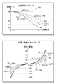
- FIG. 10 shows the relationship between the hydraulic oil discharge amount (inclination angle of the pump swash plate 523) of the hydraulic mechanical continuously variable transmission 500 and the vehicle speed of the tractor 1.
- the pump swash plate 523 is negative and has an inclination angle near the maximum (reverse rotation inclination) by driving the main speed change hydraulic cylinder 524. (See white circles), the main transmission output shaft 512 and the travel relay shaft 535 are in the lowest speed rotation state (substantially zero). As a result, the vehicle speed of the tractor 1 becomes substantially zero.
- the pump swash plate 523 When the main transmission lever 50 is operated from the neutral to the intermediate speed while the forward / reverse switching lever 36 is operated to the forward side, the pump swash plate 523 is negative and maximum when the main transmission hydraulic cylinder 524 is driven. It changes from a nearby inclination angle (reverse rotation inclination angle) through zero to a positive and maximum vicinity inclination angle (forward rotation inclination angle) (see white squares), and from the hydraulic motor unit 522 to the main transmission output shaft 512. The speed change power is increased from approximately zero to high speed. At this time, the forward low-speed hydraulic clutch 537 is in a power connection state, and the forward low-speed gear 538 or the forward high-speed gear 540 and the travel relay shaft 535 are connected so as not to be relatively rotatable.
- the forward low-speed rotational power is transmitted from the main transmission output shaft 512 to the traveling relay shaft 535 via the low-speed gear pair 525, and the traveling relay shaft 535 is rotated at the lowest speed by the increased power to the main transmission output shaft 512. It changes from the state to the forward intermediate speed rotation state (refer to the forward low speed region FL). Then, power is transmitted from the travel relay shaft 535 to the travel transmission shaft 536.
- the inclination angle is positive and near the maximum by driving the main transmission hydraulic cylinder 524.
- (Forward rotation tilt angle) changes from zero to a negative and maximum tilt angle (reverse rotation tilt angle) through zero, and the pump swash plate 523 shifts the shift power from the hydraulic motor unit 522 to the main shift output shaft 512 from a high speed. Decelerate to almost zero.
- the forward high speed hydraulic clutch 539 is in a power connection state, and the forward high speed gear 540 and the travel relay shaft 535 are coupled so as not to be relatively rotatable.
- forward high speed rotational power is transmitted from the main transmission output shaft 512 to the travel relay shaft 535 via the planetary gear mechanism 526. That is, after the power from the engine 5 and the deceleration power to the main transmission output shaft 512 are combined in the planetary gear mechanism 526, the travel relay shaft 535 is moved from the forward intermediate speed rotation state to the forward maximum speed rotation state by the combined power. Change (see forward high speed range FH). Then, power is transmitted from the travel relay shaft 535 to the travel transmission shaft 536.
- the traveling machine body 2 has the highest speed.
- the pump swash plate 523 is negative by the drive of the main transmission hydraulic cylinder 524 and the inclination angle near the maximum is reached. It changes from (reverse rotation tilt angle) to a positive and near-maximum tilt angle (forward rotation tilt angle) through zero, and the shift power from the hydraulic motor unit 522 to the main shift output shaft 512 is increased from substantially zero to high speed.
- the reverse hydraulic clutch 541 is in a power connection state, and the reverse gear 542 and the travel relay shaft 535 are coupled so as not to be relatively rotatable.
- the reverse rotational power is transmitted from the main transmission output shaft 512 to the traveling relay shaft 535 via the main transmission reverse gear 517 and the reverse gear 542, and the traveling relay shaft 535 is driven by the increased power to the main transmission output shaft 512. Changes from the lowest speed rotation state to the reverse high speed rotation state (see reverse region R). Then, power is transmitted from the travel relay shaft 535 to the travel transmission shaft 536.
- a transmission gear 547 and a creep gear 548 are provided on the rear side of the travel counter shaft 545.
- the transmission gear 547 is rotatably fitted to the travel counter shaft 545 and connected to the travel transmission shaft 536 so as to rotate integrally.
- the creep gear 548 is rotatably fitted on the travel counter shaft 545.
- a creep shifter 549 is spline-fitted between the transmission gear 547 and the creep gear 548 of the travel counter shaft 545 so as not to be relatively rotatable and slidable in the axial direction.
- the creep shifter 549 slides by turning the ultra low speed lever 44 on and off, and the transmission gear 547 and the creep gear 548 are alternatively connected to the travel counter shaft 545.
- a reduction gear pair 550 is rotatably fitted to a portion of the auxiliary transmission shaft 546 in the front chamber.
- the input side reduction gear 551 and the output side reduction gear 552 constituting the reduction gear pair 550 have an integral structure, and the transmission gear 547 of the travel counter shaft 545 always meshes with the input side reduction gear 551 of the auxiliary transmission shaft 546,
- the creep gear 548 is always meshed with the output side reduction gear 552.
- a low speed relay gear 553 and a high speed relay gear 554 are provided on the front side of the travel counter shaft 545.
- the low speed relay gear 553 is fixed to the travel counter shaft 545.
- the high-speed relay gear 554 is fitted on the travel counter shaft 545 so as not to be relatively rotatable.
- a low-speed gear 555 that meshes with the low-speed relay gear 553 and a high-speed gear 556 that meshes with the high-speed relay gear 554 are rotatably fitted on the auxiliary transmission shaft 546 on the front side of the reduction gear pair 550.
- a sub-transmission shifter 557 is spline-fitted between the low-speed gear 555 and the high-speed gear 556 in the sub-transmission shaft 546 so as not to be relatively rotatable and slidable in the axial direction.
- the sub transmission shifter 557 slides and the low speed gear 555 and the high speed gear 556 are alternatively connected to the sub transmission shaft 546.
- An intermediate position between the low speed gear 555 and the high speed gear 556 is a sub shift neutral position where the low speed gear 555 and the high speed gear 556 are not connected to the sub shift shifter 557.
- a rectilinear relay shaft 568 and a rectilinear output shaft 30 extending in parallel with the travel counter shaft 545 and the auxiliary transmission shaft 546 are disposed.
- the driven gear 569 fitted so as to be relatively non-rotatable with the straight-traveling relay shaft 568 is always meshed with the main driving gear 569 fitted so as not to be relatively rotatable on the front end side of the auxiliary transmission shaft 546.
- a straight travel relay gear 582 that is fitted to the rear end side of the straight travel relay shaft 568 so as not to be relatively rotatable, and a straight travel output gear 583 that is fitted to the straight travel output shaft 30 so as not to be relatively rotatable are always meshed.
- the main drive gear 569 of the subtransmission shaft 546, the driven gear 570 and the rectilinear relay gear 582 of the rectilinear relay shaft 568, and the rectilinear output gear 583 of the rectilinear output shaft 30 are used to linearly rotate the subtransmission shaft 456.
- a straight output gear mechanism 509 for transmitting power to the output shaft 30 is configured.
- the straight output gear mechanism 509 is provided with a straight pickup pickup rotation sensor (straight vehicle speed sensor) 823, and the straight pickup pickup rotation sensor 823 detects the rotational speed (straight vehicle speed) of the straight output.
- the straight traveling relay gear 582 is disposed so as to face the straight traveling pickup rotation sensor 823, and the rotational speed of the straight traveling output (straight traveling vehicle speed) is detected from the rotational speed of the straight traveling relay gear 582.
- the creep gear 548 is connected to the travel counter shaft 545 so as not to be relatively rotatable, and the low speed gear 555 is connected to the sub transmission shaft 546.
- a traveling driving force that is coupled so as not to be relatively rotatable and that is ultra-low speed than the straight output shaft 30 is output toward the turning mission case 13.
- the transmission gear 547 is connected to the travel counter shaft 545 so as not to rotate relative to it, and the low speed gear 555 cannot be rotated relative to the sub transmission shaft 546.
- the traveling drive force at an extremely low speed is output from the straight output shaft 30 toward the turning mission case 13.
- the transmission gear 547 is connected to the travel counter shaft 545 so as not to rotate relative to it, and the high speed gear 556 cannot be rotated relative to the sub transmission shaft 546.
- the traveling drive force at a higher speed than the straight traveling output shaft 30 is output toward the turning mission case 13.
- the auxiliary transmission lever 45 is operated to the neutral position, the auxiliary transmission shaft 546 is disconnected from the low speed gear 555 and the high speed gear 556, and the power from the traveling transmission shaft 536 is cut off by the traveling auxiliary transmission gear mechanism 503. .
- the linear transmission input countershaft 508 protruding backward from the turning mission case 13 and the linear output shaft 30 protruding forward from the lower front portion of the linear transmission case 17 are connected by a power transmission shaft 31.
- the turning mission case 13 includes a turning hydraulic continuously variable transmission (HST) 701 for appropriately changing the rotational power from the engine 5, and an output rotation from the hydraulic continuously variable transmission 701 to the left and right traveling crawlers 3 ( A differential gear mechanism 702 for transmitting to the drive sprocket 62), and a pair of left and right planetary gear mechanisms 703 for synthesizing the rotational power from the differential gear mechanism 702 and the rotational power from the straight traveling mission case 17.
- HST turning hydraulic continuously variable transmission
- a pair of hydraulic pump units 704 and a hydraulic motor unit 705 are arranged in parallel, and the power transmitted to the pump shaft 706 is transferred from the hydraulic pump unit 704 to the hydraulic motor unit 705.
- the hydraulic oil is fed appropriately.
- a charge pump 707 for supplying hydraulic oil to the hydraulic pump unit 704 and the hydraulic motor unit 705 is attached to the pump shaft 706.
- the turning hydraulic continuously variable transmission 701 changes the discharge angle and discharge amount of the hydraulic oil to the hydraulic motor unit 705 by changing and adjusting the inclination angle of the pump swash plate 708 in the hydraulic pump unit 704, thereby changing the hydraulic pressure.
- the motor shaft 709 protruding from the motor 705 is configured to arbitrarily adjust the rotation direction and the number of rotations.
- the turning input counter shaft 712 is arranged in parallel with the pump shaft 706 of the hydraulic pump unit 704, and the turning input gear 713 is fitted on the turning input counter shaft 712 so as not to be relatively rotatable. ing. Between the turning input counter shaft 712 and the pump shaft 706, a turning relay shaft 714 is arranged in parallel with the turning input counter shaft 712 and the pump shaft 706, and the turning is always meshed with the turning input gear 713.
- the relay gear 715 is fitted on the turning relay shaft 714 so as not to rotate relative to the pivot shaft 714.
- a pump input gear 710 that is always meshed with the turning relay gear 715 is fitted to the pump shaft 706 so as not to be relatively rotatable, and the rotational power transmitted from the engine 5 transmitted to the turning input counter shaft 712 is turned. It is transmitted to the pump shaft 706 via the relay shaft 714 for use.
- a differential gear mechanism 702 is configured by a bevel gear mechanism in which a pair of left and right side gears 717 are engaged with both sides of a pinion gear 716 that is fitted to the rear end of the motor shaft 709 so as not to be relatively rotatable.
- the differential gear mechanism 702 has a pair of left and right turning output shafts 718 each having a side gear 717 fitted at one end thereof so as not to rotate relative to each other.
- a turning output gear 719 for transmitting power to the pair of left and right planetary gear mechanisms 703 is fitted to the other end of each of the pair of left and right turning output shafts 718 so as not to be relatively rotatable.
- Rotational power (turning rotational power) from the hydraulic motor unit 705 output from the motor shaft 709 is branched into forward and reverse rotational power by the differential gear mechanism 702 and left and right via a pair of left and right turning output shafts 718. This is transmitted to the pair of planetary gear mechanisms 703. That is, in the differential gear mechanism 702, the reverse rotation power is transmitted to the left planetary gear mechanism 703 through the left turning output shaft 718 fitted with the left side gear 717, while the right side gear 717 is fitted. It is transmitted to the right planetary gear mechanism 703 as forward rotation power through the right turning output shaft 718.
- the hydraulic motor unit 705 of the turning hydraulic continuously variable transmission 701 is provided with a turning pickup rotation sensor (turning vehicle speed sensor) 824, and the turning pickup rotation sensor 824 detects the rotation speed (turning vehicle speed) of the turning output. It is configured to do.
- a turning pulse generating rotating wheel is provided on the motor shaft 709, and a turning pickup rotation sensor 824 is arranged to face the turning pulse generating rotating wheel, and depending on the number of rotations of the turning pulse generating rotating wheel, The number of rotations of the straight output (turning vehicle speed) is detected.
- a brake mechanism 751 that interlocks with the operation of the brake pedal 35 is provided on the straight-going input counter shaft 508 to which the rotational power from the straight-running mission case 17 is transmitted.
- the linear input gear 720 is fitted to the front end of the linear input counter shaft 508 so as not to be relatively rotatable.
- the straight travel relay shaft 721 is arranged in parallel with the straight travel input counter shaft 508, and the straight travel relay gear 722 that is always meshed with the straight travel input gear 720 is not rotatable relative to the straight travel relay shaft 721. It is fitted.
- a bevel gear mechanism is provided in which a ring gear 724 is engaged with a pinion gear 723 that is fitted to the rear end of the linear relay shaft 721 so as not to be relatively rotatable.
- the ring gear 724 cannot be relatively rotated on a straight output shaft 725 that is extended to the left and right. It is put on.
- Both ends of the straight output shaft 725 are connected to a pair of left and right planetary gear mechanisms 703, respectively.
- the rotational power (straight forward rotational power) from the straight traveling mission case 17 input to the straight traveling input counter shaft 508 is transmitted to the pair of left and right planetary gear mechanisms 703 via the straight traveling output shaft 725.
- the brake mechanism 751 performs a braking operation in accordance with the operation of the brake pedal 35, so that the rotational power of the straight output shaft 725 is attenuated or stopped.
- the left and right planetary gear mechanisms 703 rotate one sun gear 726, a plurality of planet gears 727 meshed with the sun gear 726, a ring gear 728 meshed with the turning output gear 719, and a plurality of planet gears 727 on the same circumference. And a carrier 729 which can be arranged.
- the carriers 729 of the left and right planetary gear mechanisms 703 are arranged on the same axis so as to face each other with an appropriate interval.
- the left and right sun gears 726 are fixed to both ends of a straight output shaft 725 in which a ring gear 724 is fitted in the middle.
- the left and right ring gears 728 are rotatably fitted to the straight output shaft 725, and the external teeth on the outer peripheral surface thereof are engaged with the left and right turning output gears 719 to be connected to the turning output shaft 718. ing.
- a carrier 729 fixed to the ring gear 728 rotatably supports the planetary gear 727.
- the left and right carriers 729 are rotatably fitted to the left and right differential output shafts 730.
- the left and right output transmission gears 731 that rotate together with the left and right planetary gears 727 mesh with the left and right differential input gears 732 that are non-rotatably fitted to the left and right differential output shafts 730. is doing.
- the left and right differential output shafts 730 are connected to the left and right relay shafts 735 via relay gears 733 and 734, and the left and right relay shafts 735 are connected to the left and right axles 16 via final gears 736 and 737. ing.
- Each of the left and right planetary gear mechanisms 703 receives rotational power from the straight traveling mission case 17 via the straight traveling relay shaft 721 and the straight traveling output shaft 725, and rotates the sun gear 726 at the same rotational speed in the same direction. . That is, the left and right sun gears 726 receive the rotational power from the straight traveling mission case 17 as straight traveling rotation, and transmit it to the differential output shaft 730 via the planetary gear 727 and the output side transmission gear 731. Therefore, the rotational power transmitted from the straight traveling mission case 17 to the left and right planetary gear mechanisms 703 is transmitted from the left and right axles 16 to the drive sprockets 62 at the same rotational speed in the same direction, and the left and right traveling crawlers 3 are transmitted to the same. Driven at the same rotational speed in the direction, the traveling machine body 2 is moved straight (forward, backward).
- the left and right planetary gear mechanisms 703 receive rotational power from the hydraulic motor unit 705 via the differential gear mechanism 702 and the turning output shaft 718, and cause the ring gear 728 to rotate in the opposite directions at the same rotational speed.
- Rotate That is, the left and right ring gears 728 receive rotational power from the hydraulic motor unit 705 as turning rotation, and the carrier 729 causes the turning rotation to be superimposed on the straight rotation from the sun gear 726 to rotate the planetary gear 727 and the output transmission gear 731.
- the rotational power obtained by adding the rotational rotation to the straight rotation is transmitted to one of the left and right differential output shafts 730 via the planetary gear 727 and the output-side transmission gear 731.
- Rotational power obtained by subtracting the turning rotation from the rectilinear rotation is transmitted to the other of the two through the planetary gear 727 and the output-side transmission gear 731.
- the speed change outputs from the linear input counter shaft 508 and the motor shaft 709 are transmitted to the drive sprockets 62 of the left and right traveling crawlers 3 via the left and right planetary gear mechanisms 703, respectively, so that the vehicle speed (traveling speed) of the traveling machine body 2 is increased. ) And the direction of travel is determined. That is, when the rotational power from the straight traveling mission case 17 is input to the straight traveling input counter shaft 508 with the hydraulic motor portion 705 of the hydraulic continuously variable transmission 701 stopped and the left and right ring gears 728 stationary and fixed.
- the rotation of the straight traveling input counter shaft 508 is transmitted to the left and right sun gears 726 at the same left and right rotational speed, the left and right traveling crawlers 3 are driven at the same rotational speed in the same direction, and the traveling machine body 2 travels straight.
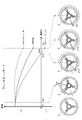
- the left and right traveling crawlers 3 are driven by driving the left and right ring gears 728 by turning the hydraulic motor portion 705 of the hydraulic continuously variable transmission 701 while driving the left and right sun gears 726 by rotating straight from the transmission case 17 for straight traveling.
- the traveling body 2 turns left or right (U-turn) with a turning radius larger than the belief turning radius while moving forward or backward. The turning radius at this time is determined according to the speed difference between the left and right traveling crawlers 3.
- the straight traveling mission case 17 is provided with a PTO transmission mechanism 505 that transmits power from the engine 5 to the PTO shaft 25.
- a PTO input shaft 591 extending coaxially with the main transmission input shaft 511 is connected to the rear end side of the main transmission input shaft 511 via a PTO hydraulic clutch 590 for power transmission interruption.
- the straight traveling mission case 17 is provided with a PTO transmission shaft 592, a PTO counter shaft 593, and a PTO shaft 25 extending in parallel with the PTO input shaft 591.
- the PTO shaft 25 protrudes rearward from the rear surface of the straight traveling mission case 17.
- the PTO input shaft 591 is provided with a medium speed input gear 597, a low speed input gear 595, a high speed input gear 596, and a reverse shifter gear 598 in order from the front side.
- the medium-speed input gear 597, the low-speed input gear 595, and the high-speed input gear 596 are fitted on the PTO input shaft 591 so as not to be relatively rotatable.
- the reverse shifter gear 598 is spline-fitted to the PTO input shaft 591 so as not to rotate relative to the PTO input shaft 591 and to be slidable in the axial direction.
- the PTO transmission shaft 592 is rotatably fitted with a PTO medium speed gear 601 meshing with the medium speed input gear 597, a PTO low speed gear 599 meshing with the low speed input gear 595, and a PTO high speed gear 600 meshing with the high speed input gear 596. is doing.
- a pair of front and rear PTO transmission shifters 602 and 603 are spline-fitted to the PTO transmission shaft 592 so as not to be relatively rotatable and to be slidable in the axial direction.
- the first PTO shift shifter 602 is disposed between the PTO medium speed gear 601 and the PTO low speed gear 599.
- the second PTO speed shifter 603 is disposed on the rear end side with respect to the PTO high speed gear 600.
- the pair of front and rear PTO shift shifters 602 and 603 are configured to slide in the axial direction in conjunction with the operation of the PTO shift lever 46.
- a PTO transmission gear 604 is fixed between the PTO low-speed gear 599 and the PTO high-speed gear 600 in the PTO transmission shaft 592.
- the PTO counter shaft 593 has a PTO counter gear 605 that meshes with the PTO transmission gear 604, a PTO relay gear 606 that meshes with a PTO output gear 608 that is non-rotatably fitted to the PTO shaft 25, and a PTO reverse gear 607. It is impossible to fit.
- the reverse shifter gear 598 slides and the reverse shifter gear 598 meshes with the PTO reverse gear 607 of the PTO counter shaft 593. ing.
- the pair of front and rear PTO shift shifters 602 and 603 slide along the PTO shift shaft 592 and the PTO low speed gear 599, the PTO medium speed gear 601 and the PTO high speed gear 600 are moved to the PTO shift shaft. 592 is alternatively connected.
- low-speed to high-speed PTO shift outputs are transmitted from the PTO shift shaft 592 to the PTO counter shaft 593 via the PTO transmission gear 604 and the PTO counter gear 605, and further, the PTO relay gear 606 and the PTO output gear 608 are transmitted. Is transmitted to the PTO shaft 25.
- the reverse shifter gear 598 meshes with the PTO reverse gear 607, and the rotational power of the PTO input shaft 591 is transmitted to the PTO counter shaft 593 via the reverse shifter gear 598 and the PTO reverse gear 607. Then, the reverse PTO shift output is transmitted from the PTO counter shaft 593 to the PTO shaft 25 via the PTO relay gear 606 and the PTO output gear 608.
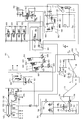
- the hydraulic circuit 620 of the tractor 1 includes a working machine hydraulic pump 481 and a traveling hydraulic pump 482 that are driven by the rotational power of the engine 5.
- the straight traveling mission case 17 is used as a working oil tank, and the working oil in the straight traveling mission case 17 is supplied to the working machine hydraulic pump 481 and the traveling hydraulic pump 482.
- the traveling hydraulic pump 482 is connected to a closed loop oil passage 623 that connects the hydraulic pump unit 521 and the hydraulic motor unit 522 in the straight-traveling hydraulic mechanical continuously variable transmission 500. While the engine 5 is being driven, the hydraulic oil from the traveling hydraulic pump 482 is always replenished to the closed loop oil passage 623.
- the traveling hydraulic pump 482 includes a main transmission hydraulic pressure switching valve 624 for the main transmission hydraulic cylinder 524 of the hydraulic mechanical continuously variable transmission 500, a PTO clutch electromagnetic valve 627 for the PTO hydraulic clutch 590, and a switching valve 628 operated thereby. And connected to. Further, the traveling hydraulic pump 482 includes a forward low speed clutch electromagnetic valve 632 that operates the forward low speed hydraulic clutch 537, a forward high speed clutch electromagnetic valve 633 that operates the forward high speed hydraulic clutch 539, and a reverse clutch that operates the reverse hydraulic clutch 541.
- the solenoid valve 634 is connected to a master control solenoid valve 635 that controls the supply of hydraulic oil to the clutch solenoid valves 632 to 634.
- the work machine hydraulic pump 481 includes a plurality of hydraulic external take-off valves 430 arranged on the upper surface of the hydraulic lifting mechanism 22 on the rear side of the upper surface of the straight traveling mission case 17, and a hydraulic lift cylinder in the hydraulic lifting mechanism 22.
- the rising hydraulic pressure switching valve 648 and the lowering hydraulic pressure switching valve 649 for controlling the hydraulic oil supply to the lower side of the lift cylinder 117, the rising control electromagnetic valve 650 for switching the rising hydraulic pressure switching valve 648, and the lowering hydraulic pressure switching valve 649 are operated.
- the double-acting valve mechanism 431 includes a hydraulic circuit including a double-acting control electromagnetic valve 432, and the ascending / descending valve mechanism 652 includes an ascending hydraulic switching valve 648, a descending hydraulic switching valve 649, an ascending control electromagnetic valve 650, and a descending A hydraulic circuit including a control solenoid valve 651 is used.
- the tilt control electromagnetic valve 647 When the tilt control electromagnetic valve 647 is switched and driven, the horizontal cylinder 122 expands and contracts, and the lower link 23 on the right side moves up and down with the lower link pin on the front side as a fulcrum. As a result, the ground work machine tilts to the left and right with respect to the traveling machine body 2 via the left and right lower links 23, and the left and right tilt angles of the ground work machine change.
- the double-acting control electromagnetic valve 432 either a single-acting type or a double-acting type can be selected as a driving method of the hydraulic lift cylinder 117.
- the drive system of the hydraulic lift cylinder 117 is set by switching the double-action control electromagnetic valve 432 in accordance with the switching operation of the single-double action switch 56.
- the hydraulic circuit 620 of the tractor 1 includes a charge pump 707 that is driven by the rotational power of the engine 5, and the charge pump 707 includes a hydraulic pump unit 704 and a hydraulic motor unit 705 in the turning hydraulic continuously variable transmission 701. Is connected to a closed-loop oil passage 740 connecting the two.
- the straight traveling mission case 17 is used as a working oil tank, and hydraulic oil in the straight traveling mission case 17 is supplied to the charge pump 707. Further, the working oil from the charge pump 707 is always replenished to the closed loop oil passage 740 while the engine 5 is being driven.
- the hydraulic circuit 620 of the tractor 1 includes a swing hydraulic cylinder 741 that changes the angle of the pump swash plate 708 of the hydraulic pump unit 704 in the hydraulic continuously variable transmission 701, and a swing hydraulic pressure switching valve 742 for the swing hydraulic cylinder 741.
- the hydraulic circuit 620 of the tractor 1 includes a lubricating oil pump 518 that is driven by the rotational power of the engine 5 in addition to the working machine hydraulic pump 481 and the traveling hydraulic pump 482 described above.
- the lubricating oil pump 518 includes a PTO clutch hydraulic pressure switching valve 641 that supplies hydraulic oil (lubricating oil) to the lubricating portion of the PTO hydraulic clutch 590, and a main transmission input shaft 511 that supports the hydraulic mechanical continuously variable transmission 500.
- the lubrication section the forward low speed clutch hydraulic pressure switching valve 642 that supplies hydraulic oil (lubricating oil) to the lubrication section of the forward low speed hydraulic clutch 537, and the forward movement that supplies hydraulic oil (lubricating oil) to the lubrication section of the forward high speed hydraulic clutch 539.
- the high-speed clutch hydraulic pressure switching valve 643 is connected to a reverse clutch hydraulic pressure switching valve 644 that supplies hydraulic oil (lubricating oil) to the lubricating portion of the reverse hydraulic clutch 541.
- the hydraulic circuit 620 includes a relief valve, a flow rate adjustment valve, a check valve, an oil cooler, an oil filter, and the like.
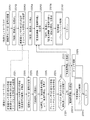
- the tractor 1 includes an engine controller 811 that controls the driving of the engine 5, a meter controller 812 that controls the display operation of the operation display panel (meter panel) 39 mounted on the dashboard 33, A linear controller 813 and a turning controller 814 that perform speed control and the like are provided.
- Each of the controllers 811 to 814 and the operation monitor 55 includes a CPU for executing various arithmetic processes and controls, a ROM for storing control programs and data, a RAM for temporarily storing control programs and data, A timer for time measurement, an input / output interface, and the like are provided, and are connected to each other via a CAN communication bus 815 so as to communicate with each other.
- the engine controller 811 and the meter controller 812 are connected to the battery 817 via the power application key switch 816.
- the fuel in the fuel tank is pumped to the common rail by the fuel pump and stored as high-pressure fuel in the common rail.
- the engine controller 811 controls the opening and closing (electronic control) of each fuel injection valve so that the high-pressure fuel in the common rail (not shown) can accurately control the injection pressure, the injection timing, and the injection period (injection amount).
- each injector (not shown) is injected into each cylinder of the engine 5.
- the liquid crystal panel and various alarm lamps in the meter panel 39 are connected to the output side of the meter controller 812. Then, the meter controller 812 outputs various signals to the meter panel 39, and controls alarm lamp turn-on / off operation, flashing operation, liquid crystal panel display operation, alarm buzzer alarming operation, and the like.
- main shift sensor main shift potentiometer
- straight pick-up rotation sensor straight vehicle speed sensor
- a forward / reverse sensor forward / reverse potentiometer
- a sub-transmission sensor 826 for detecting the operation position of the sub-transmission lever 45
- a creep for detecting the operation position of the ultra-low speed lever 44
- Sensor 827, brake position sensor 828 for detecting the depression amount of brake pedal 35, clutch position sensor 829 for detecting the depression amount of clutch pedal 37, brake switch 851 for detecting depression of brake pedal 35, and depression of clutch pedal 37 are detected.
- Clutch switch 852 and parking block Connecting the parking brake switch 853 for detecting the operation of a Kireba 43.
- a forward low speed clutch electromagnetic valve 632 that operates the forward low speed hydraulic clutch 537
- a forward high speed clutch electromagnetic valve 633 that operates the forward high speed hydraulic clutch 539
- a reverse clutch electromagnetic valve that operates the reverse hydraulic clutch 541.
- 634 and a main transmission hydraulic pressure switching valve 624 that operates the main transmission hydraulic cylinder 524 in accordance with the tilting operation amount of the main transmission lever 50 is connected.
- a steering angle sensor for detecting the turning amount (steering angle) of the steering handle 9
- a pickup pickup rotation sensor for turning that detects the rotation speed (turning vehicle speed) of the turning output.
- a turning hydraulic pressure switching valve 742 for operating the turning hydraulic cylinder 741 according to the amount of rotation operation of the steering handle 9 is connected.
- the rectilinear controller 813 includes a rectilinear travel calculation unit 831 that controls the output of a rectilinear transmission path having a hydraulic mechanical continuously variable transmission (first continuously variable transmission) 500, and steering of the steering handle 9.
- a memory 832 that stores a deceleration rate table TA that stores a deceleration rate of the straight vehicle speed with respect to a corner, and a communication interface 833 connected to the CAN communication bus 815 are provided.
- the deceleration rate table TA in the memory 832 includes “spin turn mode (first mode)”, “brake turn mode (second mode)”, and “slow turn mode (third mode)” which will be described later.
- deceleration rates TA1 to TA4 of the straight vehicle speed with respect to the steering angle of the steering handle 9 are stored.
- the deceleration rate table TA shown in FIG. 15 shows the deceleration rate when the steering handle 9 is rotated to the right in each mode (when the tractor 1 turns to the right), but the steering handle 9 is rotated to the left.
- the steering handle 9 is restricted to rotate by ⁇ e (for example, 250 °) or more from 0 ° to the left and right from the neutral position by a steering angle detection mechanism (steering box) 880.
- the deceleration rate table TA is a neutral area (so-called play area) when the steering angle of the steering handle 9 is from 0 ° (neutral position) to ⁇ mi (for example, 15 °). , Dead zone), and the deceleration rates TA1 to TA4 of each mode are 100%.
- the steering angle of the steering handle 9 is from ⁇ mi to ⁇ ma (for example, 245 °)
- the operating range of the steering handle 9 is set, and the deceleration rates TA1, TA2, TA4 of the spin turn mode, the brake turn mode, and the traveling mode, respectively. Is decreased monotonously according to the steering angle, while the deceleration rate TA3 in the gentle turning mode is kept constant at 100%.
- the steering angle ⁇ mi is the neutral position (0 °) in the control
- the steering angle ⁇ ma is the maximum steering angle in the control.
- the rate of change of the deceleration rate with respect to the steering angle increases in the order of the travel mode, the brake turn mode, and the spin turn mode.
- the deceleration rates TA1, TA2, and TA4 are minimum values De1 to De. De3 (0 ⁇ De1 ⁇ De2 ⁇ De3 ⁇ 100)%.
- the turning controller 814 includes a turning travel calculation unit 841 that controls the output of the turning system transmission path having a hydraulic continuously variable transmission (second continuously variable transmission) 701, and the steering angle of the steering handle 9.
- a memory 842 that stores a turn / straight ratio ratio table TB (see FIG. 17) that stores a turn / straight ratio of a straight vehicle speed and a turning vehicle speed, and a communication interface 843 that is connected to the CAN communication bus 815.
- the turning / straight-running ratio table TB in the memory 842 includes “spin turn mode (first mode)”, “brake turn mode (second mode)”, “slow turn mode (third mode), which will be described later. ) ”And“ traveling mode (fourth mode) ”, the turning / straight travel ratios TB1 to TB4 with respect to the steering angle of the steering wheel 9 are stored.
- the turn / straight-line ratio table TB shown in FIG. 15 shows the turn / straight-line ratio when the steering handle 9 is rotated to the right in each mode (when the tractor 1 turns right). Yes. Further, the turning / straight-ahead ratio is a ratio that is multiplied by the straight-ahead speed decelerated by the deceleration rate. When the turning / straight-ahead ratio is 0, there is no turning speed and both the left and right traveling crawlers 3 have the same straight-ahead speed. Since the turning speed increases as the turning / straight ahead ratio increases, the speed difference between the left and right traveling crawlers 3 increases.
- the turning / straight travel ratio is mainly described when the steering handle 9 is rotated to the right (when turning right), and turning when the steering handle 9 is rotated to the left (when turning left).
- the straight-line ratio is supplemented with parentheses.
- the turn / straight forward ratio table TB indicates the turn / straight forward ratios TB1 to TB4 of each mode in the neutral region where the steering angle of the steering handle 9 is 0 ° to ⁇ mi ( ⁇ mi to 0 °). And In the operation region of the steering handle 9 in which the steering angle of the steering handle 9 is ⁇ mi to ⁇ ma ( ⁇ ma to ⁇ mi), the turn / straight forward ratio of each of the spin turn mode, the brake turn mode, the slow turn mode, and the travel mode TB1 to TB4 are monotonously increased according to the steering angle. At this time, the rate of change of the turn / straight travel ratio with respect to the steering angle increases in the order of the slow turn mode, the travel mode, the brake turn mode, and the spin turn mode.
- the turn / straight travel ratio becomes the maximum value Ra1 to Ra4 (minimum value ⁇ Ra1 to ⁇ Ra4) in each mode.
- the maximum turning / straight-line ratios Ra1 to Ra4 are such that 0 ⁇ Ra1 ⁇ Ra2 ⁇ Ra3 ⁇ Ra4 (-Ra4 ⁇ -Ra3 ⁇ -Ra2 ⁇ -Ra1 ⁇ 0).
- the maximum turning / straight forward ratio Ra1 ( ⁇ Ra1) is obtained in the slow turning mode, and the maximum turning / straight forward ratio Ra2 ( ⁇ Ra2) is obtained in the traveling mode.
- the maximum turn / straight forward ratio Ra3 (-Ra3) is obtained, and in the spin turn mode, the maximum turn / straight forward ratio Ra4 (-Ra4) is obtained.
- the rectilinear travel calculation unit 831 receives a signal from the forward / reverse sensor 825, recognizes which of “forward”, “neutral”, and “reverse” is designated, Receiving signals from the speed change sensor 826 and the creep sensor 827, it is recognized which one of “high speed”, “low speed”, “super low speed”, and “neutral” is designated (STEP 1).
- the straight travel calculation unit 831 receives a signal from the main speed change sensor 822 and calculates a target value of the straight vehicle speed (hereinafter referred to as “straight forward reference target value”) in the straight travel state (the steering angle is 0 °). (STEP 2).
- the straight-ahead controller 813 receives the signal from the steering angle sensor 821 through the turning controller 814 by the communication interface 833, and gives the signal from the steering angle sensor 821 to the straight-ahead travel calculation unit 831 (STEP 3).
- the straight traveling calculation unit 831 receives the signal from the steering angle sensor 821 and recognizes the steering angle of the steering handle 9, it refers to the deceleration rate table TA in the memory 832 and controls the steering handle 9 in the designated mode.
- the deceleration rate of the straight vehicle speed corresponding to the steering angle is read (STEP 4).
- the straight travel calculation unit 831 then multiplies the straight deceleration reference target value based on the signal from the main transmission sensor 822 by the read deceleration rate, thereby obtaining a straight vehicle speed target value corresponding to the steering angle (hereinafter referred to as “straight travel target”). Value ”) is calculated (STEP 5).
- the “straight vehicle speed” in the straight travel reference target value and the straight travel target value is a relative speed of the rotational speed of the traveling transmission shaft 536 in the straight traveling mission case 17 with respect to the rotational speed of the engine 5.
- the straight traveling calculation unit 831 receives signals from the brake position sensor 828 and the clutch position sensor 829 and confirms whether or not each of the brake pedal 35 and the clutch pedal 37 is depressed (STEP 6). Then, the straight travel calculation unit 831 confirms whether or not the aircraft pedal is stopped on the brake pedal 35, whether or not the clutch pedal 37 is operated, and whether or not the forward / reverse switching lever 36 or the auxiliary transmission lever 45 is in the neutral position. (STEP7).
- the straight travel calculation unit 831 is operated when the aircraft is stopped, when the clutch pedal 37 is depressed, or when the forward / reverse switching lever 36 or the sub-shift lever 45 is in the neutral position (Yes in STEP 7). Then, a signal from the straight-ahead pickup rotation sensor 823 (hereinafter referred to as “straight-ahead actual measurement value”) is transmitted from the communication interface 833 to the turning controller 814 (STEP 8). Thereafter, in the case of forward movement, the straight traveling calculation unit 831 controls the operations of the forward low speed clutch electromagnetic valve 632, the forward high speed clutch electromagnetic valve 633, and the reverse clutch electromagnetic valve 634, and the forward low speed hydraulic clutch 537, the forward high speed clutch The hydraulic clutch 539 and the reverse hydraulic clutch 541 are disconnected (STEP 9).
- the straight travel calculation unit 831 has no airframe stop operation, no stepping operation on both clutch pedals 37, the forward / reverse switching lever 36 is in the forward position or the reverse position, and the auxiliary transmission lever 45 is When the vehicle is in any of the super low speed position, the low speed position, or the high speed position (No in STEP 7), the calculated straight target value is transmitted from the communication interface 833 to the turning controller 814 (STEP 10). Thereafter, the straight traveling calculation unit 831 controls the operations of the forward low-speed clutch electromagnetic valve 632, the forward high-speed clutch electromagnetic valve 633, and the main transmission hydraulic pressure switching valve 624 in the case of forward movement based on the calculated linear advance target value.
- the straight travel calculation unit 831 outputs the straight travel path (rotation speed by the straight travel output shaft 30) based on the straight travel actual measurement value (signal from the straight travel pickup rotation sensor 823) and the straight travel target value. Is feedback controlled (main shift control). It should be noted that the rotational speed of the traveling transmission shaft 536 is confirmed from the signal from the straight-ahead pickup rotation sensor 823 based on the transmission gear ratio specified by the signals from the auxiliary transmission sensor 826 and the creep sensor 827, and compared with the straight-ahead target value. Thus, the output of the straight-ahead transmission path is controlled.
- the turning travel calculation unit 841 receives the signal from the steering angle sensor 821, and recognizes the steering angle of the steering handle 9 (STEP 51).
- the turning traveling calculation unit 841 refers to the turning / straight ahead ratio table TB in the memory 842, and reads the turning / straight forward ratio according to the steering angle of the steering handle 9 in the designated mode (STEP 52).
- the turning controller 814 receives the signals from the auxiliary transmission sensor 826 and the creep sensor 827 through the linear controller 813 by the communication interface 843, and gives the signals to the turning calculation unit 841 (STEP 53).
- the turning travel calculation unit 841 recognizes whether “high speed”, “low speed”, or “ultra-low speed” is designated as the sub-shift based on signals from the sub-shift sensor 826 and the creep sensor 827.
- the turning traveling calculation unit 841 reads the correction value of the turning / straight-ahead ratio from the memory 842 based on the designated sub-shift, and corrects the turning / straight-ahead ratio based on the designated sub-shift (STEP 54).
- the turning controller 814 receives the straight target value or the straight measured value (signal from the straight pick-up pickup rotation sensor 823) calculated by the straight controller 813 by the communication interface 843, and gives it to the turning calculation unit 841 (STEP 55). ).
- the turning travel calculation unit 841 confirms the straight traveling vehicle speed from the straight traveling target value or the straight traveling actual measurement value, and calculates the turning target value to be the turning vehicle speed by multiplying the straight traveling vehicle speed by the corrected turning / straight traveling ratio (STEP 56). ).
- the “turning vehicle speed” in the turning target value is a relative speed of the rotational speed of the motor shaft 709 in the turning mission case 13 with respect to the rotational speed of the engine 5.
- the turning travel calculation unit 841 controls the operation of the turning hydraulic pressure switching valve 742 after calculating the turning target value. At this time, the turning travel calculation unit 841 outputs the turning system transmission path (rotation by the motor shaft 709) based on the signal from the turning pickup rotation sensor 824 (hereinafter referred to as “turning actual measurement value”) and the turning target value. (Speed) is feedback controlled (turning control) (STEP 57).
- the linear controller 813 switches the forward low-speed clutch solenoid valve 632 and the reverse clutch when the signal from the forward / reverse sensor 825 is switched from “forward to backward” or “backward to forward”.
- the electromagnetic valve 634 is controlled to switch between the forward low speed hydraulic clutch 537 and the reverse hydraulic clutch 541.
- the linear controller 813 performs control so that one of the forward low speed hydraulic clutch 537 and the reverse hydraulic clutch 541 is always connected.
- the main shift hydraulic pressure switching valve 624 is controlled by changing the rectilinear reference target value (or the rectilinear target value) so that the main shift output shaft 512 and the travel relay shaft 535 are in the lowest speed rotation state, and then again.
- the rotational speeds of the main transmission output shaft 512 and the travel relay shaft 535 are increased so that the original rotational speed is obtained. Therefore, the turning controller 814 can change the turning target value in the same way as the straight traveling target value by receiving the straight traveling target value from the straight traveling controller 813. Thereby, the turning controller 814 can reverse the output (turning vehicle speed) of the turning system transmission path with respect to the operation of the steering handle 9 when the traveling machine body 2 moves forward and backward, thereby contributing to smooth controllability to the operator.
- the linear controller 813 When the main shift control is being executed and the signal from the forward / reverse sensor 825 is in the “forward” state and the main shift lever 50 is operated to the high speed side or the low speed side, the linear controller 813 performs the forward low speed clutch electromagnetic.
- the valve 632 and the forward high speed clutch electromagnetic valve 633 are controlled to switch the forward low speed hydraulic clutch 537 and the forward high speed hydraulic clutch 539.
- the linear advance controller 813 when switching between the forward low speed hydraulic clutch 537 and the forward high speed hydraulic clutch 539, the linear advance controller 813 performs control so that one of the forward low speed hydraulic clutch 537 and the forward high speed hydraulic clutch 539 is always connected.
- the rectilinear controller 813 controls the main transmission hydraulic pressure switching valve 624 in accordance with the rectilinear target value.
- the turning controller 814 receives the straight target value from the straight controller 813 to set the output (turning vehicle speed) of the turning system transmission path for the operation of the steering handle 9, so that the forward low-speed hydraulic clutch 537 and the forward high-speed hydraulic pressure are set. Without affecting the switching of the clutch 539 and without performing complicated calculations, the output of the turning system transmission path (turning vehicle speed) corresponding to the output of the straight traveling system transmission path (straight traveling vehicle speed) can be achieved.
- the forward controller 813 controls the forward low-speed hydraulic clutch 537, the forward high-speed hydraulic clutch 539, and the reverse hydraulic clutch 541 to be disengaged by depressing the clutch pedal 37 or the like
- the signal from the pickup rotation sensor 823 is transmitted to the turning controller 814.
- the turning controller 814 sets the output (turning vehicle speed) of the turning system transmission path based on the actually measured value (signal from the straight-forward pickup rotation sensor 823).
- the output of the turning transmission path (Turning vehicle speed) can be set optimally, so that the operator can operate the vehicle without a sense of incongruity.
- the straight-forward controller 813 is configured to advance the forward low-speed hydraulic clutch 537, the forward high-speed hydraulic pressure in a high speed region where the traveling speed (straight forward vehicle speed) is equal to or higher than a predetermined speed. Control is performed so that each of the clutch 539 and the reverse hydraulic clutch 541 is disengaged. At this time, the turning controller 814 sets the output (turning vehicle speed) of the turning system transmission path based on the straight-running actual measurement value (signal from the straight-travel pickup rotation sensor 823).
- the output of the turning system transmission path (turning vehicle speed) is obtained even if the output of the straight traveling system transmission path (straight traveling vehicle speed) does not correspond to the straight traveling target value. Since the vehicle can be decelerated in accordance with the output (straight vehicle speed) of the straight transmission path, the operator can operate the vehicle without a sense of incompatibility.
- the straight traveling controller 813 adjusts to the vehicle's forward / backward travel.
- the linear advance target value is set so that the pump swash plate 523 of the hydraulic mechanical continuously variable transmission 500 is in a neutral state (0 °).
- Shift control feedback control
- the turning controller 814 may set the output of the turning system transmission path (turning vehicle speed) based on the straight traveling actual measurement value, or may set the output of the turning system transmission path based on the straight traveling target value.
- the turning controller 814 decelerates the output (turning vehicle speed) of the turning system transmission path as the output (straight running vehicle speed) of the straight running system transmission path is reduced.
- the turning controller 814 increases the output of the turning transmission path (turning vehicle speed), and the turning controller 814 reduces the output of the straight driving transmission path (straight vehicle speed).
- the speed ratio of the left and right traveling crawlers 3 during turning is determined.
- the operator operates the operation monitor 55 so that when the steering angle is large, the inside of the turn can be reversed to make a small turn (spin turn), and the spin turn mode (first mode).
- “Brake turn mode (2nd mode)” that can be executed up to the brake turn that stops the inside of the turn when the steering angle is close to the maximum when the steering angle is close to the maximum, and even more dull than the brake turn mode
- a “slow turning mode (third mode)” and a “traveling mode (fourth mode)” that can handle high vehicle speeds can be selected.
- ultra-low speed driving or low-speed driving is designated by the ultra-low speed lever 44 and the auxiliary transmission lever 45
- the turning operation by any of the “spin turn mode”, “brake turn mode”, and “slow turning mode” is performed. Allowed.
- high speed traveling is designated by the ultra low speed lever 44, only the turning operation in the “traveling mode” is permitted.
- the operator can adjust the turning force during turning in a plurality of stages by operating the operation monitor 55. Accordingly, the operator can select one of a plurality of modes by operating the operation monitor 55, and can also make stepwise adjustments. Therefore, an appropriate traveling characteristic (turning characteristic) suitable for the field situation or the like is possible. Can be selected easily.
- spin turn mode when the turning angle of the steering handle 9 becomes the angle ⁇ t1 ( ⁇ mi ⁇ t1 ⁇ ma), the inner traveling crawler 3 is stopped to travel.
- the airframe 2 is turned by a brake turn and the turning angle of the steering handle 9 exceeds the angle ⁇ t1, the inner traveling crawler 3 is rotated in the reverse direction, and the traveling airframe 2 is turned by a spin turn. That is, when the turning angle of the steering handle 9 is less than the angle ⁇ t1, the inner traveling crawler 3 is decelerated, and when the turning angle of the steering handle 9 is the angle ⁇ t1, the inner traveling crawler 3 is stopped and the steering handle 9 is cut.
- the inner traveling crawler 3 When the angle exceeds the angle ⁇ t1, the inner traveling crawler 3 is reversely rotated. Thereby, according to the operation amount of the steering handle 9, the turning center and turning radius of the traveling machine body 2 can be changed. Accordingly, the traveling machine body 2 can be turned in a state close to the sense of operation of the steering handle 9, and as a result, the traveling machine body 2 can be stably driven.
- the turning controller 814 calculates the turning target value in STEP 56
- the output from the hydraulic mechanical continuously variable transmission 500 is interrupted by the power transmission mechanism in the straight traveling mission case 17 (straight traveling transmission path).
- the reverse rotation operation by the inner traveling crawler 3 is prohibited.
- the turning target value setting operation operation of STEP 56 in FIG. 16
- the turning controller 814 determines the turning / straight forward ratio. Is replaced with a limit value ⁇ Ralim (STEP 306). Note that the limit value ⁇ Ralim of the turning / straight running ratio is set to a value smaller than 1, and the absolute value of the turning target value (turning speed) is set to be smaller than the absolute value of the straight running actual measurement value (straight speed).
- the turning controller 814 multiplies the straight vehicle speed based on the straight driving target value by the turning / straight speed ratio corrected in STEP 54, thereby obtaining the turning target value that becomes the turning vehicle speed. Calculate (STEP 308). Further, when the traveling speed of the left and right traveling crawlers 3 is the same direction as the straight traveling speed (No in STEP 305) or when there is an operation on the brake pedal 35 (Yes in STEP 307), the turning controller 814 is corrected in STEP 54. The turn target value to be the turning vehicle speed is calculated by multiplying the straight turn vehicle speed based on the straight advance actual measurement value by the turn / straight forward ratio thus obtained (STEP 309).
- the turning controller 814 sets the turning / straight running ratio to a limit value (STEP 306), the turning / straight running ratio that becomes the limit value goes straight.
- a turning target value to be the turning vehicle speed is calculated (STEP 310).
- the hydraulic clutch 537, 539, 541 or the sub-shift shifter 557 which is a power transmission mechanism in the straight transmission case 17 (straight drive transmission path), is disconnected, and the hydraulic mechanical continuously variable transmission.
- the power transmission from 500 to the straight output shaft 30 is interrupted.
- the turning controller 814 limits the turning / straight forward ratio with the limit value, thereby The reverse rotation operation by the traveling crawler 3 can be prohibited. Therefore, the differential output from the turning mission case 13 is limited when the straight-travel output shaft 30 is rotating with inertia. Therefore, even when the steering angle of the steering handle 9 is large in the brake turn mode or the spin turn mode, the traveling radius of the traveling vehicle body 2 is increased (the turning curvature is decreased), and the traveling aircraft body 2 is continuously operated. It is possible to prevent turning around.
- the turning / straight travel ratio is limited by the limit value. That is, when the left and right traveling crawlers 3 rotate in opposite directions and the left and right traveling crawlers 3 receive frictional forces in opposite directions from the ground, the turning / straight travel ratio is limited by the limit value. Furthermore, when the braking operation by the brake mechanism 751 is executed, the turning target value is calculated based on the straight running actual measurement value without limiting the turning / straight running ratio. Therefore, it is possible to always set the turning target value to the turning mission case 13 that is optimal for the traveling state of the traveling machine body 2.
- the turning controller 814 stores in the memory 842 a plurality of dead zone widths (neutral regions) - ⁇ mi to ⁇ mi of the steering handle 9 where the deceleration rate is 100% and the turning / straightness ratio is 0. .
- FIGS. 21 and 22 steering sensitivity setting control by switching the dead zone in the turning controller 814 will be described with reference to FIGS. 21 and 22.
- FIG. 21 is a flowchart showing the operation of steering sensitivity setting control
- FIG. 22 is a diagram showing the relationship between the deceleration rate and the turning / straight travel ratio set based on the change of the dead zone width.
- the dead band width (neutral region) stored in the memory 842 is stored in two types: a narrow dead band width ⁇ mi1 to ⁇ mi1 and a wide dead band width ⁇ mi2 to ⁇ mi2. More than one type of dead band width may be stored.
- the dead band width stored in the memory 842 can be changed to a value desired by the operator by operating the operation monitor 55, for example. As a result, it is possible not only to store the dead zone width optimum for the traveling state of the traveling machine body 2 and the road surface state such as a farm field or a road in the plurality of memories 842 but also to perform the steering operation optimum for the driving operation of each operator. It becomes.
- the turning controller 814 receives a signal (actually measured value of rectilinear advance) from the rectilinear pickup rotation sensor 823, confirms the rectilinear vehicle speed (STEP 601), and receives a signal from the forward / reverse sensor 825, The traveling direction (back and forth) of the traveling machine body 2 is confirmed (STEP 602).
- the straight traveling vehicle speed of the traveling machine body 2 is less than a predetermined speed, the traveling machine body 2 is traveling at a low speed (No in STEP 603), the traveling machine body 2 is traveling forward (No in STEP 604), the operation monitor 55, and the like.
- the turning controller 814 sets the narrow dead band width ⁇ mi1 to ⁇ mi1 (STEP 608).
- the turning controller 814 sets a wide dead band width ⁇ mi2 to ⁇ mi2 (STEP 609).
- the traveling machine body 2 is traveling backward (Yes in STEP 603), the turning controller 814 first sets the turning radius to be larger (STEP 605), and then changes the sensitivity by operating the operation monitor 55 or the like.
- the turning controller 814 sets a wide dead band width ⁇ mi2 to ⁇ mi2 (STEP 609).
- the turning controller 814 sets the wide dead band width ⁇ mi2 to ⁇ mi2 (STEP 609), while if the sensitivity change is requested in STEP 607. (Yes), the turning controller 814 sets the narrow dead band width ⁇ mi1 to ⁇ mi1 (STEP 608).
- the sensitivity change request is not limited to the operation during driving, but when the traveling machine body 2 is stopped, the operator performs an input operation on the operation monitor 55 or the like according to the state of the field or the road surface or the type of work, The turning controller 814 may store the flag in the memory 832 or the like.
- the turning controller 814 refers to the deceleration rate table TA and the turning / straight-head ratio table TB in the memory 832 and is currently designated according to the dead zone width after setting.
- the deceleration rate and the turn / straight-line ratio corresponding to the mode are set (STEP 610 to STEP 611).
- the deceleration rate is the minimum value at the steering angle ⁇ ma1 (- ⁇ ma1).
- the deceleration rate table TA11 is set so as to be De1
- the turning / straightness ratio table TB12 is set so that the turning / straightness ratio becomes the maximum value Ra4 at the steering angle ⁇ ma1 ( ⁇ ma1).
- the deceleration rate table TA12 is set so that the deceleration rate becomes the minimum value De1 at the steering angle ⁇ ma2 (- ⁇ ma2), while the steering angle ⁇ ma2 (- ⁇ ma2) is set.
- the steering angle ⁇ ma2 (- ⁇ ma2) is set.
- ⁇ mi1, ⁇ mi2, ⁇ ma1, and ⁇ ma2 have a relationship of 0 ⁇ mi1 ⁇ mi2 ⁇ ma1 ⁇ ma2 ⁇ e, respectively.
- the deceleration rate table TA12 having a wide dead zone width ⁇ mi2 to ⁇ mi2 is in the forward rotation side (the steering angle is a positive value and turning right) with respect to the deceleration rate table TA11 having a narrow dead zone width ⁇ mi1 to ⁇ mi1.
- ⁇ mi2 ⁇ mi1 is offset (parallel movement) in the positive direction
- the reverse rotation side (the steering angle is a negative value and the left turn) is set to be offset in the negative direction by ⁇ mi2 ⁇ mi1.
- the turning / straight-forward ratio table TB12 having a wide dead zone width ⁇ mi2 to ⁇ mi2 is also the forward rotation side (the steering angle is a positive value with the steering angle being a positive value to the right) with respect to the narrow dead zone width ⁇ mi1 to ⁇ mi1.
- (Turning) is offset (parallel movement) by ⁇ mi2 ⁇ mi1 in the positive direction, while on the reverse side (steering angle is a negative value and turning left), it is offset in the negative direction by ⁇ mi2 ⁇ mi1. Is set.
- the dead band width for the rotation of the steering handle 9 can be changed according to the traveling state. Therefore, even if the steering operation is affected by the attitude or vibration of the traveling machine body 2 , Unintended turning motion can be prevented and operability can be improved. Further, steering or shift control adapted to the traveling road surface (field) conditions or the operator's desired traveling feeling can be easily obtained, and the driving operability can be easily improved.
- the dead zone width can be set wide during high-speed traveling or reverse traveling, so that not only an unintended turning operation of the operator can be prevented, and operability can be improved, Accidents caused by inadvertent turning during high-speed or reverse travel can be prevented. Further, by making it possible to change the turning radius during backward traveling and the turning radius during forward traveling, the operability can be improved even during backward traveling where the driving operation becomes difficult due to the operator facing backward.
- the steering angle of the steering handle 9 for starting the deceleration of the straight vehicle speed (output of the straight traveling system transmission path) of the traveling machine body 2 (hereinafter referred to as “straight forward deceleration start steering angle”).
- the steering angle of the steering handle 9 that starts increasing the turning vehicle speed (output of the turning transmission path) of the traveling vehicle body 2 (hereinafter referred to as “turning acceleration start steering angle”) is set to ⁇ mi1.
- the dead zone width of the steering handle 9 is set to be narrow.
- the dead zone width of the steering handle 9 is set wide by setting the straight-ahead deceleration start steering angle and the turning acceleration start steering angle at the steering handle 9 to ⁇ mi2.
- the turning controller 814 when the turning controller 814 receives a signal from the straight-ahead controller 813 in STEP 55, the turning controller 814 confirms whether or not the brake pedal 35 is operated (STEP 307A). If the brake pedal 35 is not depressed (NO in STEP 307A), the presence / absence of operation of the clutch pedal 37 and the operation positions of the forward / reverse switching lever 36 and the auxiliary transmission lever 45 are confirmed (STEP 301 to STEP 303). On the other hand, when the depression of the brake pedal 35 is confirmed (Yes in STEP 307A), the turning target value is calculated from the straight running actual measurement value and the turning / straight running ratio (STEP 309).
- the turning controller 814 When there is no operation to the brake pedal 35 and the power transmission from the hydraulic mechanical continuously variable transmission 500 to the output shaft 30 for straight travel is interrupted (Yes in any of STEP 301 to STEP 303), the turning controller 814 When it is confirmed that the left and right traveling crawlers 3 rotate in directions opposite to each other (YES in STEP 304 and STEP 305), the turning target value is calculated from the measured value of straight travel (STEP 306, STEP 310) by replacing the turning / straight travel ratio with a limit value. ).
- the turning controller 814 calculates a turning target value based on the actual measured value and the turning / straightness ratio (STEP 309). Further, when any of the hydraulic clutches 537, 539, and 541 is connected to the auxiliary transmission shifter 557 (NO in STEP 301 to STEP 303), the turning target value is calculated from the straight traveling target value and the turning / straight running ratio (STEP 308). .
- the vehicle turns according to the measured value of straight travel and the turn / straight travel ratio regardless of the transmission of power from the hydraulic mechanical continuously variable transmission 500 to the straight output shaft 30.
- Set the target value That is, when the braking action on the straight-travel output shaft 30 is functioning, the turning target value is set based on the measured straight-running value corresponding to the rotation speed of the straight-travel output shaft 30, so the straight speed by the braking action is set. The turning speed is also reduced in accordance with the deceleration, and the traveling machine body 2 does not continuously turn around.
- the traveling aircraft body 2 may turn in a pivot while the output shaft 30 for rectilinear rotation is rotated due to inertia, the turning in a straight line can be prohibited by limiting the turning / straight ahead ratio. Unexpected behavior of the operator can be prevented, and driving safety can be improved.
- the turning controller 814 when the power transmission from the hydraulic mechanical continuously variable transmission 500 to the output shaft 30 for straight travel is interrupted (Yes in any of STEP 301 to STEP 303), the turning controller 814 is in the spin turn mode. Alternatively, it is confirmed whether any one of the brake turn modes is selected (STEP 351). When either the spin turn mode or the brake turn mode is selected (YES in STEP 351), the turning controller 814 determines the turning / straight forward ratio according to the turning / straight forward ratio table TB and the dead zone width of the selected mode. The steering angle (threshold angle) ⁇ ⁇ lim of the steering wheel 9 that becomes the limit value ⁇ Ralim is calculated (STEP 352).
- the turning controller 814 turns / The straight turn ratio is replaced with the limit value, and the turning target value is calculated from the straight advance actual measurement value (STEP 306, STEP 310).
- the steering angle ⁇ of the steering wheel 9 is within the threshold angle range ( If - ⁇ lim ⁇ ⁇ lim) (Yes in STEP 353), the turning target value is calculated from the straight-run actual measurement value and the turn / straight-forward ratio (STEP 309).
- the turning target value is calculated from the straight-run actual measurement value and the turn / straight-forward ratio (STEP 309).
- the steering angle of the steering handle 9 Since the turning / straight-running ratio is limited based on this, it is possible to prohibit the corner turning in accordance with the operation of the steering handle 9, and the operation responsiveness becomes good.
- the amount of calculation in the turning controller 814 since it is possible to set whether or not the turning / straight-running ratio is restricted without predicting the traveling direction of the traveling crawler 3, since the amount of calculation in the turning controller 814 can be reduced, the electrical responsiveness in turning control is increased, Unexpected behavior of the operator can be prevented at an early stage, and driving safety can be improved.
Landscapes
- Engineering & Computer Science (AREA)
- Mechanical Engineering (AREA)
- Chemical & Material Sciences (AREA)
- Combustion & Propulsion (AREA)
- Transportation (AREA)
- Automation & Control Theory (AREA)
- Mining & Mineral Resources (AREA)
- Civil Engineering (AREA)
- General Engineering & Computer Science (AREA)
- Structural Engineering (AREA)
- Non-Deflectable Wheels, Steering Of Trailers, Or Other Steering (AREA)
- Steering Control In Accordance With Driving Conditions (AREA)
Abstract
Description
上述したように、旋回コントローラ814による旋回目標値の設定動作について、図20のフローチャートによる動作例を、本実施形態における第1例として説明したが、当該第1実施例以外の動作例によるものとしても構わない。以下では、図23のフローチャートを参照して、旋回コントローラ814による旋回目標値の設定動作の第2例について説明する。なお、図23のフローチャートにおける動作ステップにおいて、図20のフローチャートと同一の動作ステップについては、同一の符号を付して、その詳細な説明を省略する。
次いで、図24のフローチャートを参照して、旋回コントローラ814による旋回目標値の設定動作の第3例について説明する。なお、図24のフローチャートにおける動作ステップにおいて、図20のフローチャートと同一の動作ステップについては、同一の符号を付して、その詳細な説明を省略する。
3 走行クローラ
5 ディーゼルエンジン
8 操縦座席
9 操縦ハンドル
13 旋回用ミッションケース
17 直進用ミッションケース
500 油圧機械式変速機
501 前後進切換機構
502 クリープ変速ギヤ機構
503 副変速ギヤ機構
511 主変速入力軸
512 主変速出力軸
521 油圧ポンプ部
522 油圧モータ部
523 ポンプ斜板
524 主変速油圧シリンダ
526 遊星ギヤ機構
535 走行中継軸
537 前進低速油圧クラッチ
539 前進高速油圧クラッチ
541 後進油圧クラッチ
624 主変速油圧切換弁
642 前進低速クラッチ油圧切換弁
643 前進高速クラッチ油圧切換弁
644 後進クラッチ油圧切換弁
701 油圧式無段変速機(HST)
702 差動ギヤ機構
703 遊星ギヤ機構
704 油圧ポンプ部
705 油圧モータ部
706 ポンプ軸
707 チャージポンプ
708 ポンプ斜板
709 モータ軸
741 旋回油圧シリンダ
742 旋回油圧切換弁
813 直進コントローラ
814 旋回コントローラ
821 操舵角センサ
822 主変速センサ
823 直進用ピックアップ回転センサ
824 旋回用ピックアップ回転センサ
825 前後進センサ
826 副変速センサ
827 クリープセンサ
828 ブレーキ位置センサ
829 クラッチ位置センサ
831 直進走行演算部
832 メモリ
833 通信インターフェース
841 旋回走行演算部
842 メモリ
843 通信インターフェース
880 操舵角(ハンドル切れ角)検出機構
881 ハンドル軸連結用ボス
882 操向入力軸(第1軸)
883 操向入力ギヤ(第1ギヤ)
884 操向出力軸(第2軸)
885 操向出力ギヤ(第2ギヤ)
886 ハンドル操作規制用カム
887 デテントローラ
888 デテントアーム
889 コイルバネ
890 凹部
891 凸部
892 筐体
893 天板
894 壁板
895 底板
896 ボルト
897 スペーサ
916 ブレーキペダル支持ブラケット
917 テレスコ機構
918 チルト機構
919 固定ブラケット
921 ハンドル軸
931 可動ブラケット
TA 減速率テーブル
TB 旋回/直進比テーブル
Claims (5)
- 走行機体に搭載するエンジンと、第一無段変速装置を有する直進系伝動経路と、第二無段変速装置を有する旋回系伝動経路を備え、前記直進系伝動経路の出力と前記旋回系伝動経路の出力を合成して左右の走行部を駆動する作業車両において、
前記直進系伝動経路の出力と前記旋回系伝動経路の出力とを連動的に制御する制御部と、前記直進系伝動経路からの動力伝達を継断する動力継断機構とを備えており、
前記制御部は、前記動力継断機構により前記直進系伝動経路からの動力伝達が遮断された場合、前記旋回系伝動経路の出力を制限して、前記左右の走行部による相互の逆転動作を禁止することを特徴とする作業車両。 - 前記直進系伝動経路の出力を指定する変速用操作具と、前記直進系伝動経路の出力を検出する検出器とを備え、
前記制御部は、前記変速用操作具からの指令値及び前記検出器からの実測値を択一的に選択して前記旋回系伝動経路の出力を設定するものであって、前記動力継断機構により前記直進系伝動経路からの動力伝達が遮断された場合、前記検出器からの実測値に基づいて、前記旋回系伝動経路の出力を設定することを特徴とする請求項1に記載の作業車両。 - 前記制御部は、前記動力継断機構により前記直進系伝動経路からの動力伝達が遮断されている際、前記走行部の一方の進行方向が前記走行機体の進行方向と逆方向となることを認識したとき、前記検出器からの実測値に乗算する係数を制限することで前記旋回系伝動経路の出力を制限することを特徴とする請求項1に記載の作業車両。
- 回転操作可能な操縦ハンドルを備え、
前記制御部は、前記動力継断機構により前記直進系伝動経路からの動力伝達が遮断されている際、前記操縦ハンドルの操舵角が所定角を超えたとき、前記検出器からの実測値に乗算する係数を制限することで前記旋回系伝動経路の出力を制限することを特徴とする請求項1に記載の作業車両。 - 前記制御部が、前記直進系伝動経路の出力を制御する第1制御部と、前記旋回系伝動経路の出力を制御する第2制御部とで構成されており、前記第1制御部で設定された前記直進系伝動経路の出力を前記第2制御部が受けることで、前記旋回系伝動経路の出力を設定することを特徴とする請求項1に記載の作業車両。
Priority Applications (3)
| Application Number | Priority Date | Filing Date | Title |
|---|---|---|---|
| KR1020187011156A KR102050679B1 (ko) | 2016-02-09 | 2017-02-03 | 작업 차량 |
| EP17750168.1A EP3415404B1 (en) | 2016-02-09 | 2017-02-03 | Working vehicle |
| US16/076,653 US10926795B2 (en) | 2016-02-09 | 2017-02-03 | Work vehicle |
Applications Claiming Priority (2)
| Application Number | Priority Date | Filing Date | Title |
|---|---|---|---|
| JP2016-022543 | 2016-02-09 | ||
| JP2016022543A JP6473091B2 (ja) | 2016-02-09 | 2016-02-09 | 作業車両 |
Publications (1)
| Publication Number | Publication Date |
|---|---|
| WO2017138444A1 true WO2017138444A1 (ja) | 2017-08-17 |
Family
ID=59563194
Family Applications (1)
| Application Number | Title | Priority Date | Filing Date |
|---|---|---|---|
| PCT/JP2017/003897 WO2017138444A1 (ja) | 2016-02-09 | 2017-02-03 | 作業車両 |
Country Status (5)
| Country | Link |
|---|---|
| US (1) | US10926795B2 (ja) |
| EP (1) | EP3415404B1 (ja) |
| JP (1) | JP6473091B2 (ja) |
| KR (1) | KR102050679B1 (ja) |
| WO (1) | WO2017138444A1 (ja) |
Cited By (2)
| Publication number | Priority date | Publication date | Assignee | Title |
|---|---|---|---|---|
| US20180268696A1 (en) * | 2017-03-16 | 2018-09-20 | Toyota Jidosha Kabushiki Kaisha | Collision avoidance device |
| RU2771060C2 (ru) * | 2017-11-22 | 2022-04-25 | КЛААС Зельбстфаренде Эрнтемашинен ГмбХ | Система управления для сельскохозяйственной рабочей машины |
Families Citing this family (7)
| Publication number | Priority date | Publication date | Assignee | Title |
|---|---|---|---|---|
| EP3299263B1 (en) * | 2015-05-22 | 2021-09-01 | Yanmar Power Technology Co., Ltd. | Method of assembling a tractor |
| JP6514958B2 (ja) * | 2015-05-25 | 2019-05-15 | ヤンマー株式会社 | 作業車両 |
| JP6438368B2 (ja) * | 2015-09-18 | 2018-12-12 | ヤンマー株式会社 | 作業車両 |
| JP7266383B2 (ja) | 2018-10-26 | 2023-04-28 | 株式会社小松製作所 | 作業機械およびその制御方法 |
| JP7358164B2 (ja) * | 2019-09-30 | 2023-10-10 | 株式会社小松製作所 | 制御システム、作業車両の制御方法、および、作業車両 |
| US11472395B2 (en) | 2020-02-28 | 2022-10-18 | Cnh Industrial America Llc | System and method for executing multi-mode turns with a work vehicle |
| US12071743B2 (en) * | 2020-10-30 | 2024-08-27 | Caterpillar Inc. | Coordinated actuator control by an operator control |
Citations (4)
| Publication number | Priority date | Publication date | Assignee | Title |
|---|---|---|---|---|
| JP2000025642A (ja) * | 1998-07-10 | 2000-01-25 | Yanmar Agricult Equip Co Ltd | 移動農機 |
| JP2001163241A (ja) * | 1999-12-13 | 2001-06-19 | Yanmar Agricult Equip Co Ltd | クローラ走行車 |
| JP2005067606A (ja) * | 2004-10-25 | 2005-03-17 | Seirei Ind Co Ltd | 作業車 |
| JP2014144008A (ja) * | 2014-03-20 | 2014-08-14 | Yanmar Co Ltd | 農業用作業車両 |
Family Cites Families (7)
| Publication number | Priority date | Publication date | Assignee | Title |
|---|---|---|---|---|
| JP3681871B2 (ja) * | 1997-09-16 | 2005-08-10 | ヤンマー農機株式会社 | 移動農機 |
| JP2002059753A (ja) | 2000-08-21 | 2002-02-26 | Seirei Ind Co Ltd | 走行車両 |
| JP3950358B2 (ja) * | 2002-04-24 | 2007-08-01 | 株式会社 神崎高級工機製作所 | 作業車の操向装置 |
| JP3945698B2 (ja) * | 2002-10-23 | 2007-07-18 | ヤンマー農機株式会社 | クローラ形トラクタ |
| JP2004330829A (ja) * | 2003-05-02 | 2004-11-25 | Kanzaki Kokyukoki Mfg Co Ltd | 走行車両の操向駆動装置 |
| JP4247078B2 (ja) | 2003-09-09 | 2009-04-02 | ヤンマー株式会社 | 油圧装置 |
| JP5435881B2 (ja) * | 2008-03-04 | 2014-03-05 | ヤンマー株式会社 | 走行車両 |
-
2016
- 2016-02-09 JP JP2016022543A patent/JP6473091B2/ja active Active
-
2017
- 2017-02-03 WO PCT/JP2017/003897 patent/WO2017138444A1/ja active Application Filing
- 2017-02-03 KR KR1020187011156A patent/KR102050679B1/ko active IP Right Grant
- 2017-02-03 EP EP17750168.1A patent/EP3415404B1/en active Active
- 2017-02-03 US US16/076,653 patent/US10926795B2/en active Active
Patent Citations (4)
| Publication number | Priority date | Publication date | Assignee | Title |
|---|---|---|---|---|
| JP2000025642A (ja) * | 1998-07-10 | 2000-01-25 | Yanmar Agricult Equip Co Ltd | 移動農機 |
| JP2001163241A (ja) * | 1999-12-13 | 2001-06-19 | Yanmar Agricult Equip Co Ltd | クローラ走行車 |
| JP2005067606A (ja) * | 2004-10-25 | 2005-03-17 | Seirei Ind Co Ltd | 作業車 |
| JP2014144008A (ja) * | 2014-03-20 | 2014-08-14 | Yanmar Co Ltd | 農業用作業車両 |
Cited By (3)
| Publication number | Priority date | Publication date | Assignee | Title |
|---|---|---|---|---|
| US20180268696A1 (en) * | 2017-03-16 | 2018-09-20 | Toyota Jidosha Kabushiki Kaisha | Collision avoidance device |
| US10755573B2 (en) * | 2017-03-16 | 2020-08-25 | Toyota Jidosha Kabushiki Kaisha | Collision avoidance device |
| RU2771060C2 (ru) * | 2017-11-22 | 2022-04-25 | КЛААС Зельбстфаренде Эрнтемашинен ГмбХ | Система управления для сельскохозяйственной рабочей машины |
Also Published As
| Publication number | Publication date |
|---|---|
| JP6473091B2 (ja) | 2019-02-20 |
| JP2017140893A (ja) | 2017-08-17 |
| EP3415404A4 (en) | 2019-02-27 |
| US20190047620A1 (en) | 2019-02-14 |
| KR102050679B1 (ko) | 2019-11-29 |
| KR20180054802A (ko) | 2018-05-24 |
| EP3415404A1 (en) | 2018-12-19 |
| US10926795B2 (en) | 2021-02-23 |
| EP3415404B1 (en) | 2020-05-27 |
Similar Documents
| Publication | Publication Date | Title |
|---|---|---|
| JP6473091B2 (ja) | 作業車両 | |
| JP6438368B2 (ja) | 作業車両 | |
| JP6487824B2 (ja) | 作業車両 | |
| WO2016189917A1 (ja) | 作業車両 | |
| JP6470158B2 (ja) | 作業車両 | |
| JP6515044B2 (ja) | 作業車両 | |
| WO2017057352A1 (ja) | 作業車両 | |
| JP6487774B2 (ja) | 作業車両 | |
| JP6487869B2 (ja) | 作業車両 | |
| JP6435284B2 (ja) | 作業車両 | |
| JP2017143804A (ja) | 作業車両 | |
| JP2017074889A (ja) | 作業車両 | |
| JP6487868B2 (ja) | 作業車両 |
Legal Events
| Date | Code | Title | Description |
|---|---|---|---|
| 121 | Ep: the epo has been informed by wipo that ep was designated in this application |
Ref document number: 17750168 Country of ref document: EP Kind code of ref document: A1 |
|
| ENP | Entry into the national phase |
Ref document number: 20187011156 Country of ref document: KR Kind code of ref document: A |
|
| NENP | Non-entry into the national phase |
Ref country code: DE |
|
| WWE | Wipo information: entry into national phase |
Ref document number: 2017750168 Country of ref document: EP |
|
| ENP | Entry into the national phase |
Ref document number: 2017750168 Country of ref document: EP Effective date: 20180910 |