WO2017138333A1 - オットマン装置 - Google Patents
オットマン装置 Download PDFInfo
- Publication number
- WO2017138333A1 WO2017138333A1 PCT/JP2017/001994 JP2017001994W WO2017138333A1 WO 2017138333 A1 WO2017138333 A1 WO 2017138333A1 JP 2017001994 W JP2017001994 W JP 2017001994W WO 2017138333 A1 WO2017138333 A1 WO 2017138333A1
- Authority
- WO
- WIPO (PCT)
- Prior art keywords
- cover
- seat
- link
- width direction
- movable
- Prior art date
- Legal status (The legal status is an assumption and is not a legal conclusion. Google has not performed a legal analysis and makes no representation as to the accuracy of the status listed.)
- Ceased
Links
Images








Classifications
-
- A—HUMAN NECESSITIES
- A47—FURNITURE; DOMESTIC ARTICLES OR APPLIANCES; COFFEE MILLS; SPICE MILLS; SUCTION CLEANERS IN GENERAL
- A47C—CHAIRS; SOFAS; BEDS
- A47C7/00—Parts, details, or accessories of chairs or stools
- A47C7/50—Supports for the feet or the legs
-
- B—PERFORMING OPERATIONS; TRANSPORTING
- B60—VEHICLES IN GENERAL
- B60N—SEATS SPECIALLY ADAPTED FOR VEHICLES; VEHICLE PASSENGER ACCOMMODATION NOT OTHERWISE PROVIDED FOR
- B60N3/00—Arrangements or adaptations of other passenger fittings, not otherwise provided for
- B60N3/06—Arrangements or adaptations of other passenger fittings, not otherwise provided for of footrests
Definitions
- the present invention relates to an ottoman device.
- Japanese Patent Laying-Open No. 2015-160473 discloses a vehicle seat provided with an ottoman device.
- This vehicle seat has a main cover and a sub-cover that cover the deployment storage mechanism of the ottoman device from the outside. Then, at least a part of the main cover and the sub cover are arranged so as to wrap in a side view at the storage position and the leg mounting position of the ottoman device.
- the present invention is intended to provide an ottoman device that can reduce the danger to passengers in consideration of the above facts.
- the base bracket can be rotated by the base bracket connected to the front end portion of the seat cushion frame constituting the skeleton of the vehicle seat and the link pin with the seat width direction as the axial direction.
- a link mechanism portion configured to include a supported drive link, which is operated by rotating the drive link to rotate the ottoman main body between a retracted position and a leg rest position, and the base bracket.
- a fixed cover that is fixed and covers the base bracket from the outside in the seat width direction, and a connecting shaft that covers the link mechanism portion from the outside in the seat width direction on the outside in the seat width direction and is coaxially arranged with the link pin
- a movable cover that is pivotally connected to the fixed cover and configured to rotate integrally with the drive link; It is provided between the fixed cover and the movable cover, is pivotally connected to the fixed cover with the axis of the connecting shaft as a rotation center, and the rotation of the movable cover from the retracted position to the leg mounting position.
- An intermediate cover that engages with the movable cover at an intermediate position in the middle of movement and rotates together with the movable cover toward the leg placement position, and at the leg placement position, the fixed cover, the intermediate cover, and An ottoman device is provided in which the movable cover is continuously arranged in the circumferential direction of the connecting shaft.
- the link mechanism portion includes the base bracket and the drive link.
- the base bracket is connected to the front end portion of the seat cushion frame, and the drive link is rotatably supported by the base bracket by a link pin whose axial direction is the seat width direction. Then, when the drive link is rotated, the link mechanism is operated, and the Ottoman main body is rotated between the storage position and the leg placement position.
- a fixed cover is fixed to the base bracket, and the base bracket is covered from the outside in the seat width direction by the fixed cover.
- a movable cover that covers the link mechanism portion from the outside in the seat width direction is provided on the outside in the seat width direction of the fixed cover.
- the movable cover is rotatably connected to the fixed cover by a connecting shaft arranged coaxially with the link pin, and the movable cover is configured to be rotatable integrally with the drive link.
- an intermediate cover is provided between the fixed cover and the movable cover, and the intermediate cover is rotatably connected to the fixed cover.
- the cover mechanism which covers a link mechanism part from a sheet
- the intermediate cover is rotatably connected to the fixed cover with the axis of the connecting shaft as the rotation center. Then, when the drive link is rotated and the link mechanism is activated, the intermediate cover is engaged with the movable cover at the intermediate position in the middle of the rotation from the retracted position of the movable cover to the leg placement position. It rotates together with the cover toward the leg placement position.
- the intermediate cover and the movable cover can be developed into a fan shape with the connecting shaft as the center in accordance with the operation of the link mechanism.
- the fixed cover, the intermediate cover, and the movable cover are continuously arranged in the circumferential direction of the connecting shaft at the leg mounting position. For this reason, it is possible to prevent an occupant's finger or the like from being sandwiched between the fixed cover and the intermediate cover and between the intermediate cover and the movable cover. As described above, the danger to passengers can be reduced.
- the intermediate cover may be configured as a single cover.
- the cover mechanism is configured by three covers: a fixed cover, an intermediate cover, and a movable cover. For this reason, the link mechanism can be covered with the three covers of the fixed cover, the intermediate cover, and the movable cover while suppressing an increase in the number of parts.
- the intermediate cover is formed with a first groove extending in a circumferential direction of the connecting shaft, and the movable cover is formed with the intermediate cover.
- a first protrusion that protrudes toward the cover and is disposed inside the first groove is formed. In the retracted position, the first protrusion is disposed at one end of the first groove, and the movable cover is The first protrusion may be moved from one end to the other end of the first groove by rotating from the retracted position to the intermediate position.
- the first protrusion of the movable cover that protrudes toward the intermediate cover is disposed inside the first groove of the intermediate cover.
- the first protrusion In the retracted position, the first protrusion is disposed at one end of the first groove, and when the movable cover rotates from the retracted position to the intermediate position, the first protrusion moves from one end of the first groove to the other end. Moved. For this reason, when the movable cover is rotated from the storage position to the intermediate position, relative movement of the movable cover with respect to the intermediate cover is allowed, and only the movable cover can be rotated.
- the first protrusion of the movable cover At the intermediate position, the first protrusion of the movable cover is disposed at the other end of the first groove and engaged with the other end.
- the intermediate cover is rotated together with the movable cover to the leg placement position side.
- the movable cover and the intermediate cover can be deployed in this order.
- a biasing member that biases the intermediate cover toward the storage position is provided between the fixed cover and the intermediate cover.
- a second groove extending in a circumferential direction of the connecting shaft is formed in the intermediate cover, and the fixed cover protrudes toward the intermediate cover and is disposed inside the second groove.
- a second protrusion is formed, and in the storage position, the second protrusion is disposed at one end of the second groove, and the intermediate cover is rotated from the storage position to the leg placement position side, The second groove may be rotated relative to the second protrusion, and the second protrusion may be disposed at the other end of the second groove.
- the second protrusion of the fixed cover that protrudes toward the intermediate cover is disposed inside the second groove of the intermediate cover.
- the second protrusion In the retracted position, the second protrusion is disposed at one end of the second groove, and the intermediate cover is biased toward the retracted position by the biasing member.
- the end of the second groove can be engaged with the second protrusion by the urging force of the urging member, and the rotation of the intermediate cover can be limited. Accordingly, the intermediate cover can be favorably held at the storage position when the movable cover is rotated from the storage position to the intermediate position.
- the intermediate cover when the movable cover rotates from the intermediate position to the leg rest position, the intermediate cover is rotated together with the movable cover from the retracted position to the leg rest position side. At this time, the second groove rotates relative to the second protrusion, and the second protrusion is disposed at the other end of the second groove. For this reason, relative rotation of the intermediate cover with respect to the fixed cover can be allowed.
- an engaging portion is formed at a distal end portion of the movable cover, and a distal end portion of the intermediate cover is An engaged portion that is engaged with the engaging portion in the sheet width direction may be formed at the intermediate position.
- the engaged portion formed at the front end portion of the intermediate cover is engaged in the sheet width direction with the engaging portion formed at the front end portion of the movable cover at the intermediate position. For this reason, the relative movement between the intermediate cover and the movable cover in the sheet width direction is limited by the engagement of the engaging portion and the engaged portion. Thereby, in the unfolded state of the movable cover and the intermediate cover, relative movement between the movable cover and the intermediate cover in the sheet width direction can be suppressed, and the movable cover and the intermediate cover can be integrated. Therefore, the rigidity in the sheet width direction of the movable cover and the intermediate cover in the unfolded state can be increased.
- the fixed cover is formed with a protrusion protruding toward the intermediate cover, and the protrusion May be formed in a hemispherical shape and capable of contacting the intermediate cover.
- the intermediate cover when the intermediate cover rotates relative to the fixed cover, the intermediate cover can be brought into contact with the protruding portion formed on the fixed cover.
- the protrusion since the protrusion is formed in a hemispherical shape, the protrusion is brought into point contact with the intermediate cover when the protrusion and the intermediate cover are brought into contact with each other. Thereby, the sliding loss when the intermediate cover rotates relative to the fixed cover can be reduced.
- the danger to passengers can be reduced.
- the link mechanism portion can be covered with the three covers of the fixed cover, the intermediate cover, and the movable cover while suppressing an increase in the number of parts.
- the movable cover and the intermediate cover can be deployed in this order.
- the intermediate cover when the movable cover is rotated from the retracted position to the intermediate position, the intermediate cover is satisfactorily held at the retracted position, while the movable cover is rotated from the intermediate position to the leg rest position.
- the intermediate cover When moving, relative movement of the intermediate cover with respect to the fixed cover can be allowed.
- the rigidity in the sheet width direction of the movable cover and the intermediate cover in the unfolded state can be increased.
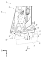
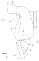
- FIG. 1 is an exploded perspective view of a main part of a vehicle seat to which the ottoman device according to the present embodiment is applied, viewed from the front obliquely left of the seat.
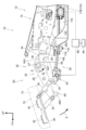
- FIG. 2 is a side view of the ottoman device shown in FIG. 1 as viewed from the left side of the seat, showing a state where the ottoman device is disposed at the first storage position.
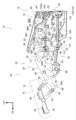
- FIG. 3 is a side view as seen from the left side of the seat showing a state in which the slide mechanism and the link mechanism shown in FIG. 1 are operated and the ottoman device is disposed at the leg placement position.
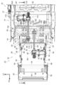
- FIG. 4 is a bottom view of the ottoman device shown in FIG. 3 as seen from the lower side of the seat, showing the state of the leg placement position.
- FIG. 5 is a cross-sectional view (cross-sectional view taken along line 5-5 in FIG. 4) viewed from the left side of the seat, showing a connection state between the first bracket and the second bracket in the slide mechanism shown in FIG.
- FIG. 6 is a perspective view of the ottoman device shown in FIG. 3 as viewed from the lower right side of the seat, showing the state of the leg placement position. It is the perspective view seen from the sheet
- FIG. 7B is a cross-sectional view (cross-sectional view taken along the line 7B-7B in FIG. 7A) viewed from the left side of the sheet, showing a joined state between the rear end portion of the connecting plate and the base plate shown in FIG. FIG.
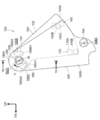
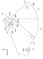
- FIG. 8 is a side view seen from the left side of the seat showing the state of the cover mechanism in the first retracted position of the ottoman device shown in FIG.
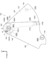
- FIG. 9 is a side view of the ottoman device shown in FIG. 3 as viewed from the left side of the seat, showing the state of the cover mechanism at the leg placement position.
- FIG. 10 is an exploded perspective view of the main part of the cover mechanism disposed on the left side of the seat of the ottoman device as viewed from the front left of the seat.
- FIG. 11 is an exploded perspective view of the main part of the cover mechanism shown in FIG.
- FIG. 12 is a side view of the cover mechanism shown in FIG.
- FIG. 13 is a side view seen from the left side of the seat showing a state in which the movable cover shown in FIG.
- FIG. 14 is a side view seen from the left side of the seat showing a state in which the movable cover shown in FIG. 15 is a cross-sectional view (a cross-sectional view taken along the line 15-15 in FIG. 12) viewed from the front side of the seat, showing an enlarged connection state of the cover mechanism shown in FIG.
- FIG. 16 is a perspective view showing an engagement state between the pocket portion of the intermediate cover and the engagement claw portion of the movable cover in the expanded state of the cover mechanism shown in FIG. 14.
- An arrow FR appropriately shown in the drawings indicates the front side of the vehicle seat 10
- an arrow UP indicates the upper side of the seat
- an arrow LH indicates the left side of the seat (one side in the seat width direction).
- the vehicle seat 10 includes a seat body 12 and an ottoman device 20.
- the seat body 12 includes a seat cushion SC and a seat back SB.
- the ottoman device 20 is connected to the front end portion of the seat cushion SC via a slide mechanism 80 (see FIG. 1).
- the ottoman device 20 has an ottoman body 70 for supporting a leg (sheath part) of a seated occupant.
- the ottoman main body 70 is stored in the storage position shown in FIG. 2 (see the ottoman main body 70 indicated by a two-dot chain line in FIG. 2), and the slide mechanism 80 (see FIG. 1) is activated.
- the entire ottoman device 20 slides to the front side of the seat (in the direction of arrow A in FIG. 2), and the storage position of the ottoman main body 70 is changed to the front side of the seat (indicated by a one-dot chain line in FIG. 2). (See Ottoman body 70).
- the ottoman device 20 is actuated, whereby the ottoman main body 70 is rotated in the direction of arrow B in FIG. 2 and is arranged at the leg placement position shown in FIG. ing.
- the storage position of the ottoman body 70 indicated by a two-dot chain line in FIG. 2 is referred to as a first storage position, and the storage position of the ottoman body 70 indicated by a one-dot chain line in FIG. This is called the storage position.
- the seat body 12 includes a seat cushion frame 14 that constitutes the skeleton of the seat cushion SC and a seat back frame 18 that constitutes the skeleton of the seat back SB.
- the seat cushion frame 14 has a pair of left and right side frames 16 that constitute both side portions of the seat cushion frame 14 in the seat width direction.
- the side frame 16 is formed in a substantially long plate shape that extends in the front-rear direction of the seat, and is arranged with the seat width direction as the plate thickness direction.
- a flange portion 16 ⁇ / b> A that is bent inward in the seat width direction is formed on the outer periphery of the side frame 16.
- the side frame 16 is connected with the floor part of the vehicle by the conventionally well-known seat slide mechanism (illustration omitted).
- the seat body 12 is configured to be slidable in the seat front-rear direction with respect to the floor portion of the vehicle.
- the seat back frame 18 is provided on the seat upper side of the rear end portion of the side frame 16, and the lower end portion of the seat back frame 18 is connected to the rear end portion of the side frame 16 via a reclining mechanism RS.
- the reclining mechanism RS is well known in the art, and the relative angle (reclining angle) of the seat back frame 18 with respect to the seat cushion frame 14 can be adjusted by the reclining mechanism RS.
- a seat pad (not shown) is attached to the seat cushion frame 14 and the seat back frame 18, and the surface of each seat pad is covered with a seat skin (not shown).
- the ottoman device 20 includes an ottoman main body 70 for supporting a leg of a seated occupant and a link mechanism 22 that operates to place the ottoman main body 70 at a leg resting position.
- the ottoman device 20 includes a pair of left and right cover mechanisms 130 that cover the link mechanism 22 (not shown in FIGS. 8 and 9) from the outside in the seat width direction.
- the link mechanism 22 and the ottoman main body 70 will be described, and the configuration of the cover mechanism 130 will be described later.
- the link mechanism 22 includes a pair of left and right link mechanism portions 24 that constitute both side portions of the link mechanism 22 in the sheet width direction, and a link for operating the link mechanism portion 24. And a drive unit 50. Further, the pair of left and right link mechanism portions 24 include a base bracket 26, a drive link 28, a movable link 32, a first intermediate link 34, a second intermediate link 36, and a driven link 38, respectively. They are arranged side by side in the sheet width direction.
- the base bracket 26 is made of a metal plate or the like, and is formed in a substantially T-shaped plate shape in which the sheet width direction is the plate thickness direction. Between the pair of left and right base brackets 26, a first bracket 82 constituting a slide mechanism 80 to be described later is bridged, and the pair of left and right base brackets 26 are connected by the first bracket 82. Further, between the pair of left and right base brackets 26, the first rod 52 as a round rod-shaped “rod” constituting the slide drive unit 110 in the slide mechanism 80 described later at a position below the seat of the first bracket 82. (See FIGS. 4 to 6). The first rod 52 is disposed with the seat width direction as an axial direction, and both longitudinal ends of the first rod 52 are joined to the pair of left and right base brackets 26. The base bracket 26 is connected to the seat cushion frame 14 by a slide mechanism 80 described later.
- a wire 44 for fixing a fixing cover 132 (see FIG. 8) of a cover mechanism 130 (see FIG. 8), which will be described later, is fixed to the outside of the base bracket 26 in the seat width direction by welding or the like.
- the wire 44 is formed in a substantially rectangular frame shape that is partially opened to the upper side of the sheet in a side view. And the part which comprises the front-end part of the wire 44 is made into the front side wire part 44F, and the front side wire part 44F is extended in the sheet
- the portion extending from the upper end of the front wire portion 44F to the rear side of the seat is an upper wire portion 44U
- the portion extending from the lower end of the front wire portion 44F to the rear side of the seat is the lower wire portion 44L. It is said that.
- a portion extending from the rear end of the lower wire portion 44L to the upper side of the sheet is a rear wire portion 44R.
- a first fixing bracket 46 for fixing a fixing cover 132 of a cover mechanism 130 described later is provided between the base bracket 26 and the wire 44.
- the first fixed bracket 46 is formed in a substantially rectangular plate shape in which the sheet width direction is the plate thickness direction, and the outer peripheral portion of the first fixed bracket 46 is welded to the lower wire portion 44L and the rear wire portion 44R. It is fixed by.
- a fixing screw portion 46A penetrating in the seat width direction is formed at a substantially central portion of the first fixing bracket 46, and a female screw is formed on the inner peripheral surface of the fixing screw portion 46A.
- the drive link 28 is formed in a substantially long plate shape and is disposed on the inner side in the seat width direction of the base bracket 26 with the seat width direction being the plate thickness direction. Yes.
- One end portion of the drive link 28 in the longitudinal direction is rotatably connected to the front end portion of the base bracket 26 by a link pin LP whose axial direction is the seat width direction.
- a hollow round bar-like connecting rod 30 is provided between the pair of left and right drive links 28.
- the connecting rod 30 is disposed with the seat width direction as an axial direction, and both longitudinal ends of the connecting rod 30 are joined to the other longitudinal ends of the pair of left and right drive links 28.
- a substantially fixed plate-like second fixing bracket 48 for fixing a movable cover 180 (see FIG. 9) of a cover mechanism 130 described later is provided.
- the second fixed bracket 48 is formed in a substantially crank shape in which both end portions in the longitudinal direction are bent to opposite sides.
- the base end portion of the second fixed bracket 48 is joined to the inner side surface of the drive link 28 in the seat width direction, and the second fixed bracket 48 extends outward from the drive link 28 in the seat width direction.
- a fixing screw portion 48A penetrating in the seat width direction is formed at a substantially central portion at the distal end portion of the second fixing bracket 48, and a female screw is formed on the inner peripheral surface of the fixing screw portion 48A.
- the movable link 32 is formed in a substantially long plate shape and is disposed on the outer side in the seat width direction of the base bracket 26 with the seat width direction as the plate thickness direction.
- One end of the movable link 32 in the longitudinal direction is connected to the base bracket 26 so as to be rotatable about the seat width direction as an axial direction at a position below the seat of the link pin LP.
- the first intermediate link 34 is formed in a substantially long plate shape, and is disposed on the outer side of the drive link 28 in the sheet width direction with the sheet width direction being the plate thickness direction. Further, one end portion in the longitudinal direction of the first intermediate link 34 is coupled to the other end portion in the longitudinal direction of the drive link 28 so as to be rotatable about the sheet width direction as an axial direction. The rotation axis at one longitudinal end of the first intermediate link 34 is arranged coaxially with the axis of the connecting rod 30 (see FIG. 5).
- the second intermediate link 36 is formed in a substantially long plate shape, and is disposed outside the drive link 28 in the sheet width direction with the sheet width direction being the plate thickness direction.
- the longitudinal intermediate portion of the second intermediate link 36 is coupled to the longitudinal intermediate portion of the drive link 28 so as to be rotatable about the sheet width direction as an axial direction.
- one end portion in the longitudinal direction of the second intermediate link 36 is supported by the other end portion in the longitudinal direction of the movable link 32 so as to be rotatable about the sheet width direction as an axial direction.
- the driven link 38 is formed in a substantially long plate shape, and is disposed outside the first intermediate link 34 and the second intermediate link 36 in the sheet width direction with the sheet width direction being the plate thickness direction.
- the other end in the longitudinal direction of the first intermediate link 34 is supported on the intermediate portion in the longitudinal direction of the driven link 38 so as to be rotatable about the sheet width direction as an axial direction.
- the other end portion of the second intermediate link 36 in the longitudinal direction is supported at one end portion in the longitudinal direction of the driven link 38 so as to be rotatable about the sheet width direction as an axial direction.
- the link mechanism part 24 is arrange
- the ottoman device 20 is illustrated as being slid to the front side of the seat by a slide mechanism 80 described later.
- a first support plate 40 and a second support plate 42 for supporting an ottoman body 70 (see FIG. 3) to be described later are bridged between a pair of left and right driven links 38. Yes. Specifically, the first support plate 40 is bridged between the longitudinal ends of the pair of left and right driven links 38, and the second support plate 42 is the other longitudinal end of the pair of left and right driven links 38. It is bridged between the clubs.
- the link driving unit 50 includes the first rod 52, the link motor unit 60, and the second rod 58 for connecting the link motor unit 60 to the drive link 28. It is comprised including. Further, the link drive unit 50 has a link feed screw 64 for rotating the drive link 28 relative to the base bracket 26. That is, the link drive unit 50 is configured as a so-called feed screw mechanism.
- the first rod 52 is bridged between the pair of left and right base brackets 26 as described above.
- a first connecting bracket 54 for connecting a link feed screw 64 (described later) to the first rod 52 is provided at the center in the longitudinal direction of the first rod 52.
- the first connection bracket 54 is formed in a substantially U shape that is open to the upper side of the seat, and the front end portion of the first connection bracket 54 protrudes to the front side of the seat and is fixed to the first rod 52.
- a link nut 56 as a “link support member” is provided in the first connection bracket 54, and the link nut 56 is pivotally supported by the first connection bracket 54 with the seat width direction as an axial direction.
- a through hole is formed in the central portion of the link nut 56, and the through hole is penetrated in a direction orthogonal to the sheet width direction.
- the internal thread is formed in the inner peripheral part of a through-hole.
- the second rod 58 has a hollow round bar shape and is disposed between the pair of left and right drive links 28 with the seat width direction as the axial direction. The both ends of the second rod 58 in the longitudinal direction are fixed to the middle portion in the longitudinal direction of the pair of left and right drive links 28.
- a link motor bracket 59 for supporting the link motor unit 60 is fixed to the second rod 58.
- the link motor unit 60 is supported by the link motor bracket 59 so as to be rotatable about the seat width direction as an axial direction.
- the link motor unit 60 includes a link motor 62, and the link motor 62 is connected to a link feed screw 64 described later. Further, a controller 66 (see FIG. 3) is electrically connected to the link motor 62, and the link motor 62 is operated under the control of the controller 66.
- the link feed screw 64 is formed in a substantially round bar shape, and is disposed between the link nut 56 and the link motor unit 60 with the direction orthogonal to the sheet width direction as the axial direction.
- One end of the link feed screw 64 in the longitudinal direction is disposed in the link motor unit 60, is rotatably supported by the link motor unit 60, and is connected to the link motor 62. Accordingly, the link feed screw 64 is configured to rotate forward or backward around its own axis by operating the link motor 62.
- a male screw is formed on the outer periphery of the link feed screw 64. The link feed screw 64 is screwed into the link nut 56 at the other longitudinal end of the link feed screw 64.
- the link feed screw 64 when the link feed screw 64 is rotated forward or reverse by the operation of the link motor 62, the link feed screw 64 is moved relative to the link nut 56 in its own axial direction.
- the link nut 56 is connected to the first rod 52 so as not to be relatively movable. Therefore, when the link feed screw 64 moves relative to the link nut 56 in the axial direction, the second rod 58 moves relative to the first rod 52. Specifically, when the link feed screw 64 is rotated forward, the link feed screw 64 is moved relative to the link nut 56 so as to be extended from the link nut 56.
- the link motor unit 60 and the second rod 58 are displaced toward the seat front side with respect to the first rod 52, and the drive link 28 is rotated around the axis of the link pin LP (in the direction of arrow C in FIG. 2).
- the link mechanism 24 is developed.
- the link feed screw 64 rotates in the reverse direction, the link feed screw 64 moves relative to the link nut 56 so as to move backward toward the link nut 56.
- the link motor unit 60 and the second rod 58 are displaced toward the rear side of the seat with respect to the first rod 52, and the drive link 28 rotates about the axis of the link pin LP (in the direction of arrow D in FIG. 2).
- the link mechanism 24 is folded.
- the ottoman body 70 is disposed on the surface side of the first support plate 40 and the second support plate 42.
- the ottoman body 70 has a leg mounting pad 72 made of a foam material such as urethane, and the leg mounting pad 72 is supported by the first support plate 40 and the second support plate 42 through a finisher (not shown).
- a trim is provided on the surface side of the leg mounting pad 72, and the leg mounting pad 72 is covered with the trim.
- the ottoman body 70 has a pair of left and right ottoman cover portions 74.
- the ottoman cover portion 74 is formed in a substantially sector plate shape with the sheet width direction as the plate thickness direction, and covers a part of the movable cover 180 of the cover mechanism 130 described later from the outside in the sheet width direction. .
- the ottoman main body 70 When the ottoman main body 70 is disposed at the first retracted position indicated by the two-dot chain line in FIG. 2, the ottoman main body 70 moves toward the lower side of the seat in a side view at the position on the front side of the seat cushion frame 14. Accordingly, it is set to be slightly inclined toward the rear side of the seat.
- the ottoman body 70 is slid from the first storage position indicated by the two-dot chain line in FIG. 2 to the second storage position indicated by the one-dot chain line in FIG.
- the link mechanism 22 is configured to rotate so that the ottoman main body 70 is moved up to the seat upper side while moving to the seat front side.
- the slide mechanism 80 includes a first bracket 82 provided on the ottoman device 20, a second bracket 90 provided on the seat cushion frame 14, and a “slider”. As a slide bolt 98.
- the slide mechanism 80 includes a slide drive unit 110 (see FIGS. 4 and 6) for operating the slide mechanism 80.
- the ottoman device 20 is slidably connected to the seat cushion frame 14 by a slide mechanism 80.
- each configuration of the slide mechanism 80 will be described.
- the first bracket 82 is made of a metal plate or the like.
- the first bracket 82 extends in the seat width direction, and is formed in a substantially L shape in a side view as viewed from the left side of the seat.
- the first bracket 82 includes a substantially rectangular plate-like slide plate 84 arranged with the sheet vertical direction as the plate thickness direction, and a front plate 86 extending from the front end of the slide plate 84 to the upper side of the seat. , Including.
- the front end portion of the slide plate 84 and the lower end portion of the front plate 86 are joined by welding or the like.
- the first bracket 82 is disposed between the pair of left and right base brackets 26 and above the seat of the first rod 52 (see FIG. 5). It is joined to the base bracket 26 by welding or the like. As a result, the base bracket 26 is also connected by the first bracket 82, and the first bracket 82 is configured so as not to move relative to the ottoman device 20. In the present embodiment, the first bracket 82 is configured by the separate slide plate 84 and front plate 86, but the first bracket 82 may be configured as an integral part.
- a pair of weld nuts 88F and 88R are fixed on the upper surface of the slide plate 84 with the seat vertical direction as the axial direction.
- the weld nuts 88F and 88R are respectively disposed at both ends of the slide plate 84 in the sheet width direction.
- the weld nuts 88F and 88R which make a pair are spaced apart and arrange
- a pair of front and rear weld nuts 88F and 88R are arranged side by side in the seat width direction.
- the pair of front and rear weld nuts 88F and 88R disposed on the left side of the seat of the slide plate 84 and the pair of front and rear weld nuts 88F and 88R disposed on the right side of the seat of the slide plate 84 are the seat of the slide plate 84. It is arranged at a position symmetrical to the center line in the width direction. A through hole is formed in the slide plate 84 at a position corresponding to the weld nuts 88F and 88R.
- the first rod 52 is disposed between the weld nut 88F disposed on the front side of the seat and the weld nut 88R disposed on the rear side of the seat when viewed from the vertical direction of the seat. As described above, the positions of the weld nuts 88F and 88R in the longitudinal direction of the seat are set.
- the second bracket 90 is made of a metal plate or the like.
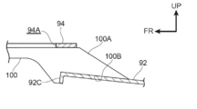
- the second bracket 90 includes a base plate 92, a support plate 94, and a plurality (four in this embodiment) of connection plates 100 that connect the base plate 92 and the support plate 94.
- the base plate 92 is formed in a substantially rectangular plate shape with the sheet width direction as the longitudinal direction, and is arranged with the sheet vertical direction as the plate thickness direction.
- Crank portions 92A that are bent in a substantially crank shape to the lower side of the seat and the outer side in the seat width direction are formed at both ends of the base plate 92 in the seat width direction.
- a pair of front and rear welding groove portions 92B are formed through both ends of the base plate 92 in the sheet width direction.
- the pair of front and rear welding groove portions 92B extend in the front-rear direction of the seat and are arranged side by side in the front-rear direction of the seat. As shown in FIG.
- both end portions in the seat width direction of the base plate 92 are disposed below the seat of the side frame 16 in the seat cushion frame 14, and the flange of the side frame 16 is located at the position of the welding groove 92 ⁇ / b> B. It is joined to the part 16A by welding or the like. As a result, the second bracket 90 is spanned across the pair of left and right side frames 16.
- a base flange 92C is formed at the front end portion of the base plate 92 as a pair of left and right “folded portions” that is bent to the lower side of the seat.
- the base flange 92C is arranged side by side in the seat width direction at a position between the pair of left and right crank portions 92A.
- the support plate 94 is formed in a substantially rectangular plate shape, and is disposed on the sheet front side and the sheet upper side of the base plate 92 with the sheet vertical direction as the plate thickness direction.
- the support plate 94 is connected to the base plate 92 by a connection plate 100 described later. Further, the support plate 94 is disposed below the seat of the slide plate 84 between the front end portions of the side frames 16 in the seat cushion frame 14. Further, the position of the support plate 94 in the sheet width direction is set so that the sheet width direction center line of the support plate 94 and the sheet center line of the base plate 92 coincide.
- a support front plate 96 is provided at the front end portion of the support plate 94.
- the support front plate 96 is formed in a substantially long plate shape with the sheet width direction as the longitudinal direction, and is disposed with the sheet front-rear direction as the plate thickness direction.
- the upper end portion of the support front plate 96 is the support plate 94. It is joined to the front end of this by welding or the like.
- the support plate 94 and the support front plate 96 are configured as separate members, but the support plate 94 and the support front plate 96 may be configured as a single member. That is, the front end portion of the support plate 94 may be bent to the lower side of the seat to form the support front plate 96.
- the support plate 94 is formed with a pair of left and right elongated holes 94A extending in the front-rear direction of the seat at portions on both ends of the seat width direction.
- the long hole 94A is disposed at a position corresponding to the weld nuts 88F and 88R (see FIG. 1) paired in the front-rear direction described above.
- the extending length of the long hole 94A is set to be longer than the distance between the pair of front and rear weld nuts 88F and 88R.
- a resin collar 95 is integrally provided on the inner peripheral portion of the long hole 94A.
- the collar 95 is formed in a frame shape corresponding to the shape of the long hole, covers the inner peripheral surface of the long hole 94A, and slightly protrudes above the upper surface of the support plate 94 to the upper side of the sheet. Accordingly, a pair of left and right slide grooves 95 ⁇ / b> A extending in the front-rear direction of the seat is formed through the support plate 94 in the inner portion of the collar 95.
- slide bolts 98 that are paired in the longitudinal direction of the seat are inserted from the lower side of the seat.
- the slide bolt 98 is configured as a stepped bolt. That is, the slide bolt 98 includes a head 98A, a cylindrical bolt main body 98B extending from the head 98A to the upper side of the seat, and a screw portion 98C extending from the upper end of the bolt main body 98B to the upper side of the seat. It is configured to include.
- the slide bolt 98 is inserted into the slide groove 95A from the lower side of the seat through the washer W, and the screw portions 98C of the slide bolt 98 are screwed into the weld nuts 88F and 88R, respectively. Further, when the slide bolt 98 is screwed into the weld nuts 88F and 88R, the upper end of the bolt main body 98B is set so as to slightly protrude from the collar 95 to the upper side of the seat. Accordingly, the bolt main body 98B is configured to slide in the front-rear direction of the seat inside the slide groove 95A.
- the first bracket 82 connected to the ottoman device 20 (the base bracket 26 thereof) is connected to the support plate 94 so as to be slidable in the front-rear direction of the seat by the slide bolt 98, and from the lower side of the seat by the support plate 94. It is supported.
- the position where the seat rear slide bolt 98 is disposed at the rear end portion of the slide groove 95A is referred to as an initial position, and the seat front slide bolt 98 is the front end of the slide groove 95A.
- the position arranged in the section is referred to as a slide position (position shown in FIG. 5).
- the ottoman body 70 is disposed at the first retracted position indicated by a two-dot chain line at the initial position of the slide mechanism 80, and at the slide position of the slide mechanism 80.
- the main body 70 is arranged at a second storage position indicated by a one-dot chain line.
- the slide amount (distance from the initial position to the slide position) of the first bracket 82 is set to 70 mm as an example.
- the connecting plate 100 is formed in a substantially long plate shape, and extends in the front-rear direction of the seat from the front end to the rear end of the support plate 94 on the lower side of the support plate 94.
- the connecting plate 100 is disposed on both sides in the sheet width direction with respect to the slide groove 95A of the support plate 94, with the sheet width direction as the plate thickness direction.
- the connecting plate 100 disposed on the outer side in the sheet width direction with respect to the slide groove 95 ⁇ / b> A is disposed on the lower side of the sheet at both ends in the sheet width direction of the support plate 94.
- the front end of the connection plate 100 is joined to the rear surface of the support front plate 96 by welding or the like, and the upper end of the connection plate 100 is joined to the lower surface of the support plate 94 by welding or the like.
- the rear end portion of the connecting plate 100 is a connecting portion 100A, and the connecting portion 100A protrudes from the support plate 94 to the rear side of the seat and is inclined to the lower side of the seat in the side view. Yes.
- a notch 100B opened to the lower side of the seat and the rear side of the seat is formed at the lower end of the connecting portion 100A.
- the notch 100B is joined to the upper surface of the base plate 92 and the front surface of the base flange 92C by welding or the like. Accordingly, the rear end portion (connecting portion 100A) of the connecting plate 100 is supported by the base plate 92 from the lower side of the seat and the rear side of the seat.
- the slide driving unit 110 slides the first rod 52, the slide motor unit 116, and the first rod 52 with respect to the seat cushion frame 14 in the front-rear direction of the seat.
- the slide feed screw 122 is configured. That is, the slide drive unit 110 is configured as a so-called feed screw mechanism. Further, the first rod 52 described above is configured as a common component used in common in the slide drive unit 110 and the link drive unit 50.
- the first rod 52 is bridged between the pair of left and right base brackets 26 in the link mechanism portion 24.
- the first rod 52 is provided with a second connection bracket 112 for connecting a slide feed screw 122, which will be described later, to the first rod 52.
- the second connection bracket 112 is the first connection bracket 54 described above. Is arranged on the left side of the seat.
- the second connection bracket 112 is formed in a substantially U shape that is open to the upper side of the seat, and the distal end portion of the second connection bracket 112 is fixed to the first rod 52.
- a slide nut 114 as a “slide support member” is provided in the second connection bracket 112.
- the sliding nut 114 is pivotally supported by the second connecting bracket 112 with the seat width direction as the axial direction. Further, a through hole penetrating in the front-rear direction of the seat is formed inside the sliding nut 114, and a female screw is formed on the inner peripheral portion of the through hole.
- the slide motor unit 116 is disposed on the rear side of the seat of the slide nut 114 and is fixed to the lower surface of the base plate 92 via the slide motor bracket 120.
- the slide motor unit 116 has a slide motor 118, and the slide motor 118 is connected to a slide feed screw 122 described later.
- the above-described control unit 66 (see FIG. 3) is electrically connected to the slide motor 118, and the slide motor 118 is operated by the control of the control unit 66.
- the slide feed screw 122 is formed in a substantially round bar shape and extends in the front-rear direction of the seat.
- a rear end portion (one end portion) of the slide feed screw 122 is disposed in the slide motor unit 116, is rotatably supported by the slide motor unit 116, and is connected to the slide motor 118.
- the slide feed screw 122 is configured to rotate forward or backward around its own axis by operating the slide motor 118.
- a male screw is formed on the outer periphery of the slide feed screw 122.
- the front end side (the other end side) of the slide feed screw 122 is screwed to the slide nut 114.
- the slide feed screw 122 is rotated forward or backward by the operation of the slide motor 118, so that the slide nut 114 (first rod 52) moves relative to the slide feed screw 122 in the longitudinal direction of the seat. It is supposed to be. Specifically, when the slide feed screw 122 rotates forward, the slide nut 114 (first rod 52) moves relative to the slide feed screw 122 relative to the seat front side. On the other hand, when the slide feed screw 122 rotates in the reverse direction, the slide nut 114 (first rod 52) moves relative to the slide feed screw 122 relative to the seat rear side.
- the first bracket 82 that is, the ottoman device 20
- the second bracket 90 that is, the seat cushion frame 14
- the vehicle seat 10 is provided with an operation unit 68 for operating the ottoman device 20 and the slide mechanism 80, and the operation unit 68 is connected to the control unit 66. Electrically connected.
- the operation unit 68 has, for example, a use button that is operated when the ottoman device 20 is used, and a storage button that is operated when the ottoman device 20 is stored.
- the slide mechanism 80 is activated, and the link mechanism 22 of the ottoman device 20 is activated after the slide mechanism 80 is activated.
- the ottoman body 70 is arranged from the first storage position indicated by the two-dot chain line in FIG. 2 to the second storage position indicated by the one-dot chain line in FIG.
- the ottoman body 70 is arranged from the leg placement position to the second storage position, and is arranged from the second storage position to the first storage position.
- the cover mechanism 130 constitutes both sides of the ottoman device 20 in the sheet width direction.
- the cover mechanism 130 is configured to cover the link mechanism 24 of the ottoman device 20 from the outside in the seat width direction.
- the cover mechanism 130 disposed on the left side of the seat and the cover mechanism 130 disposed on the right side of the seat are configured symmetrically. Therefore, in the following description, the cover mechanism 130 disposed on the left side of the seat will be described, and the description of the cover mechanism 130 disposed on the right side of the seat will be omitted.
- the cover mechanism 130 is configured to include a cover in three of a fixed cover 132, an intermediate cover 160, and a movable cover 180.
- these covers are made of a resin material.
- the resin material of these covers is not prescribed
- These covers may be made of an aluminum alloy or the like.
- the fixed cover 132, the intermediate cover 160, and the movable cover 180 are arranged so as to overlap in a side view.
- this state of the cover mechanism 130 is referred to as a non-deployed state, and the position of the cover mechanism 130 in the non-deployed state corresponds to the storage position of the present invention.
- the fixed cover 132 and the intermediate cover 160 are deployed to the front side of the seat with respect to the fixed cover 132.
- this state of the cover mechanism 130 is referred to as an unfolded state, and the position of the cover mechanism 130 in the unfolded state corresponds to the leg placement position of the present invention.
- the position of the movable cover 180 in the cover mechanism 130 shown in FIG. 13 is referred to as an intermediate position.
- each configuration of the cover mechanism 130 will be described.
- the fixed cover 132 is formed in a substantially sector plate shape with the sheet width direction being the plate thickness direction, and the base bracket 26 (see FIG. 15) in the link mechanism portion 24 (see FIG. 3). (See Fig. 1) in the sheet width direction outside.
- the fixed cover 132 has a base end portion 132A formed in a substantially circular shape centering on the axis AL of the link pin LP in the link mechanism portion 24, and extends substantially fan-shaped from the base end portion 132A obliquely rearward on the lower side of the seat.
- the front half of the base end portion 132A protrudes toward the seat front side with respect to the cover portion 132B.
- the front surface of the cover portion 132B extends from the outer peripheral surface of the base end portion 132A to the lower side of the seat, and the rear surface of the cover portion 132B is in contact with the outer peripheral surface of the base end portion 132A and from the outer peripheral surface to the seat bottom. It is extended diagonally backward. Further, the distal end of the cover portion 132B is formed in an arc shape centered on the center line of the base end portion 132A (the axis line AL of the link pin LP described above) in a side view.
- a first locking claw 134 is integrally formed on the proximal side portion of the cover portion 132B on the inner side surface in the sheet width direction.
- the first locking claw 134 is formed in a substantially inverted L shape when viewed from the side.
- the first locking claw 134 includes a first side wall 134A that protrudes inward in the sheet width direction from the fixed cover 132 with the sheet vertical direction as a plate thickness direction, and a sheet lower side at a front end portion of the first side wall 134A. And a second side wall 134B bent to the right.
- the first locking claw 134 includes a first top wall 134C extending from the front end portion of the first side wall 134A to the lower side of the seat and a first top wall 134C extending from the front end portion of the second side wall 134B to the rear side of the seat. 2 top walls 134D.
- the bending part between the front side wire part 44F and the upper side wire part 44U of the wire 44 in the link mechanism part 24 shown in FIG. 1 is arrange
- a second locking claw 136 is integrally formed on the inner side surface in the sheet width direction at the front end side (lower end side) portion of the cover portion 132B.
- the second locking claws 136 have a side wall 136A that protrudes inward in the sheet width direction from the fixed cover 132 with the sheet vertical direction as the plate thickness direction, and a top wall 136B that extends downward from the front end of the side wall 136A. , Including.
- the lower wire portion 44 ⁇ / b> L of the wire 44 in the link mechanism 22 shown in FIG. 1 is disposed inside the second locking claw 136, and the second locking claw 136 is locked to the wire 44.
- cover portion 132B is integrally formed with a cover fixing portion 138 for fixing the fixing cover 132 to the base bracket 26 (see FIG. 15) at a position on the rear side of the seat of the second locking claw 136.
- the cover fixing portion 138 is formed in a substantially bottomed cylindrical shape having a shallow bottom and protrudes inward in the seat width direction from the fixing cover 132, and corresponds to the first fixing bracket 46 of the base bracket 26 shown in FIG. Placed in position.
- a through hole 138A is formed at the center of the bottom wall of the cover fixing portion 138, and a screw (not shown) is inserted into the through hole 138A from the outside in the seat width direction to fix the fixing screw portion 46A (see FIG. 1). ). Accordingly, the fixed cover 132 is fixed to the base bracket 26 via the wire 44 and the first fixing bracket 46 shown in FIG.
- a first accommodating portion 140 for accommodating a torsion spring 200 described later is formed at the base end portion 132 ⁇ / b> A of the fixed cover 132.
- the first accommodating portion 140 is formed in a substantially bottomed cylindrical shape having a shallow bottom and projecting inward in the sheet width direction.
- the base end portion 132 ⁇ / b> A is formed with a second housing portion 142 for housing a spring locking portion 168 (see FIG. 11) of the intermediate cover 160 described later, on the radially outer side of the first housing portion 140. Yes.
- the second accommodating portion 142 extends in the circumferential direction of the first accommodating portion 140 in a side view, protrudes inward in the sheet width direction from the fixed cover 132, and is open to the outer side in the sheet width direction. Is formed. And the inside of the 2nd accommodating part 142 and the inside of the 1st accommodating part 140 are connected.
- a substantially cylindrical support shaft 144 is integrally formed at the center portion of the bottom wall of the first housing portion 140. As shown also in FIG. 15, the support shaft 144 protrudes outward in the seat width direction from the bottom wall of the first accommodating portion 140 and is coaxial with the link pin LP of the link mechanism portion 24 (see FIG. 3) described above. Is placed on top.
- a hexagon nut 146 is integrally provided in the support shaft 144 by insert molding or the like, and the hexagon nut 146 is disposed coaxially with the link pin LP.
- a locking groove 148 for locking one end portion of a torsion spring 200 described later is formed on the inner end surface 132 ⁇ / b> A of the fixed cover 132 on the inner side surface in the sheet width direction.
- the locking groove 148 extends along the radial direction of the first housing portion 140, and the base end portion of the locking groove 148 communicates with the inside of the first housing portion 140.
- the first accommodation portion 140 is formed with a communication hole 150 that communicates the inside of the first accommodation portion 140 and the inside of the locking groove 148.
- a torsion spring 200 as an “urging member” is accommodated in the first accommodating portion 140, and the torsion spring 200 is pivotally supported by a support shaft 144 (see FIG. 15).
- One end of the torsion spring 200 is accommodated in the locking groove 148 via the communication hole 150 and locked in the locking groove 148 (see FIG. 15).
- the fixed cover 132 is integrally formed with an annular rib 152 that protrudes outward in the seat width direction at a position radially outward of the first accommodating portion 140. , Partly open (specifically, open at the part of the second accommodating portion 142), it is formed in a substantially annular shape.
- the fixed cover 132 is integrally formed with a fixed boss 154 as a “second protrusion” at a position radially outside the first housing portion 140, and the fixed boss 154 is formed on the outer side in the sheet width direction. It is formed in a cylindrical shape protruding to
- a pair of projecting portions 156 are integrally formed on the outer side surface in the sheet width direction of the cover portion 132B at the front end position.
- the projecting portion 156 is disposed at the edge portion on the front surface side of the cover portion 132B, and is spaced apart in the vertical direction of the seat.
- the protruding portion 156 is formed in a substantially hemispherical shape, and the protruding height of the protruding portion 156 is set to be the same as the protruding height of the annular rib 152.
- the intermediate cover 160 is formed in a substantially fan-like plate shape with the sheet width direction as the plate thickness direction, and is disposed outside the fixed cover 132 in the sheet width direction.
- the outer shape of the intermediate cover 160 is set to the same shape as the outer shape of the fixed cover 132. That is, the intermediate cover 160 includes a base end portion 160A and a cover portion 160B that extends from the base end portion 160A in a substantially fan shape obliquely rearward on the lower side of the seat.
- a circular support hole 162 is formed through the central portion of the base end portion 160A of the intermediate cover 160.
- the support shaft 144 of the fixed cover 132 is inserted into the support hole 162, and the intermediate cover 160 is pivotally supported by the support shaft 144 (see FIG. 15).
- the intermediate cover 160 has the rotation axis one side (the arrow C direction side in FIGS. 10 and 11) and the rotation direction the other side (see FIG. 15) with the axis AL of the link pin LP (see FIG. 15) as the rotation center. 10 and the direction of arrow D in FIG. 11) is connected to the fixed cover 132 so as to be rotatable. Further, as shown in FIGS.
- an accommodation recess 164 that is open to the outside in the sheet width direction is formed around the support hole 162 on the outer surface in the sheet width direction of the base end portion 160 ⁇ / b> A.
- the housing recess 164 is formed in an annular shape along the circumferential direction of the support hole 162.
- the base end portion 160A is formed with a first groove 166A and a second groove 166B forming a pair on the outer side in the radial direction of the support hole 162.
- the first groove 166A is disposed on the front side of the support hole 162 and the second groove 166B is disposed on the rear side of the support hole 162.
- the first groove 166 ⁇ / b> A and the second groove 166 ⁇ / b> B are curved in a substantially arc shape with the support hole 162 as the center, and extend along the circumferential direction of the support hole 162.
- the lower end portion of the first groove 166A is one end portion 166A1 of the first groove 166A, and the first groove 166A extends from the one end portion 166A1 to one side in the rotation direction (arrow C direction side). Yes.
- the lower end of the second groove 166B is one end 166B1 of the second groove 166B, and the second groove 166B extends from the one end 166B1 to the other side in the rotational direction (arrow D direction side). Yes.
- the fixed side boss 154 of the fixed cover 132 is inserted into the second groove 166B.
- the fixed side boss 154 is inserted into the one end 166B1 of the second groove 166B.
- a spring locking portion 168 is integrally formed on the inner surface of the base end portion 160 ⁇ / b> A in the sheet width direction at a position below the seat of the support hole 162. In the side view, it extends along the diagonally lower front side of the seat. Further, when viewed from the longitudinal direction of the spring locking portion 168, the tip end portion of the spring locking portion 168 is bent upward of the seat. Further, the spring locking portion 168 is housed in the second housing portion 142 of the fixed cover 132. The other end portion of the torsion spring 200 is locked to the spring locking portion 168, and the intermediate cover 160 is urged to the other side in the rotational direction (arrow D direction side) by the torsion spring 200.
- one end 166B1 of the second groove 166B is engaged with the fixed-side boss 154 (see FIG. 10), and the intermediate cover 160 is rotated in the other direction (arrow D direction). Side) is restricted. That is, the intermediate cover 160 is held in a non-deployed state.
- a pocket portion 170 as an “engaged portion” is integrally formed on the front end portion of the cover portion 160B on the outer surface in the seat width direction.
- the pocket portion 170 has a substantially rectangular shape in a side view, is formed in a pocket shape opened to the rear side of the seat, and is disposed close to the front surface of the cover portion 160B. Further, a substantially U-shaped engaging groove 170B opened to the rear side of the seat is formed through the top wall 170A of the pocket portion 170.
- the movable cover 180 is formed in a substantially fan-shaped plate centered on the axis AL of the link pin LP (see FIG. 15), with the sheet width direction as the plate thickness direction, The cover 160 is disposed outside the sheet width direction.
- the movable cover 180 includes a base end portion 180A arranged around the axis AL of the link pin LP, and a cover portion 180B extending from the base end portion 180A obliquely rearward to the lower side of the seat in a substantially fan shape. It is configured to include. Further, as shown in FIG.
- the front surface of the cover portion 180B extends in the vertical direction of the seat, and the rear surface of the cover portion 180B extends along the diagonally rear side of the lower side of the seat.
- the upper outer peripheral surface of the base end portion 180A is formed in an arc shape centering on the axis AL of the link pin LP in a side view and is in contact with the front surface and the rear surface of the cover portion 180B. More specifically, the radius of the upper outer peripheral surface of the base end portion 180A is the same as the radius of the base end portion 132A (see FIG. 10) of the fixed cover 132 and the base end portion 160A (see FIG. 10) of the intermediate cover 160. Is set. In the non-deployed state of the cover mechanism 130, the movable cover 180, the intermediate cover 160, and the fixed cover 132 are overlapped in the sheet width direction except for the rear end portions of the intermediate cover 160 and the fixed cover 132. Is set.
- a protruding portion 180C that protrudes to the lower side of the seat is formed at the front end portion of the cover portion 180B.
- the overhanging portion 180C is formed in a substantially trapezoidal shape in a side view, and the outer peripheral portion of the overhanging portion 180C (see FIG. 11) is smoothly connected to the distal end portion of the movable cover 180.
- the base end portion 180 ⁇ / b> A of the movable cover 180 is integrally formed with a mounting portion 182 having a shallow bottom and a substantially bottomed cylindrical shape protruding inward in the seat width direction.
- the attachment portion 182 is disposed coaxially with the support shaft 144 of the fixed cover 132, and the seat width direction inner side portion of the attachment portion 182 is rotatably accommodated in the accommodation recess 164 of the intermediate cover 160. (See FIG. 15).
- an attachment hole 182A is formed through the bottom wall of the attachment portion 182, and the attachment hole 182A is disposed coaxially with the support shaft 144 of the fixed cover 132. Then, as shown in FIG.
- the connecting bolt 202 as the “connecting shaft” is inserted into the mounting hole 182 ⁇ / b> A, and the connecting bolt 202 is screwed into the hexagon nut 146, so that the movable cover 180 is moved.
- the fixed cover 132 is pivotally connected. That is, the axis of the connecting bolt 202 coincides with the axis AL of the link pin LP, and the movable cover 180 is rotatably connected to the fixed cover 132 around the axis AL of the link pin LP.
- the connecting bolt 202 is configured as a so-called stepped bolt. That is, the connecting bolt 202 includes a head 202A, a cylindrical bolt body 202B protruding from the head 202A inward in the seat width direction, and a screw portion 202C protruding from the bolt body 202B inward in the seat width direction. It is configured to include. Further, the axial length of the bolt main body 202B is set to be longer than the thickness of the bottom wall of the mounting portion 182. The screw portion 202C is screwed into the hexagon nut 146 so that the front end surface of the bolt main body 202B comes into contact with the front end surface of the support shaft 144.
- a cover fixing portion 184 for fixing the movable cover 180 to the drive link 28 is integrally formed on the overhang portion 180C of the cover portion 180B.
- the cover fixing portion 184 is formed in a substantially bottomed cylindrical shape that protrudes inward in the seat width direction from the movable cover 180 and corresponds to the second fixing bracket 48 (see FIG. 1) of the drive link 28. It is arranged at the position to do.
- a through hole 184A is formed at the center of the bottom wall of the cover fixing portion 184.
- a screw (not shown) is inserted into the through hole 184A from the outside in the seat width direction and screwed into the fixing screw portion 48A. ing.
- the movable cover 180 is fixed to the drive link 28 via the second fixed bracket 48.
- the movable cover 180 is configured to be rotatable integrally with the drive link 28 around the axis of the link pin LP (connection bolt 202) shown in FIG.
- an annular rib 186 protruding inward in the seat width direction is integrally formed at the base end portion 180 ⁇ / b> A of the movable cover 180 at a position radially outside the attachment portion 182.
- the rib 186 is formed in a substantially annular shape.
- the front end surface of the annular rib 186 is brought into contact with the outer surface of the intermediate cover 160 in the sheet width direction.
- a movable side boss 188 as a “first protrusion” is integrally formed on the base end portion 180A at a position radially outside the attachment portion 182.
- the movable side boss 188 is formed in a substantially cylindrical shape. And protrudes inward in the sheet width direction.
- the movable boss 188 is inserted into the first groove 166A of the intermediate cover 160 described above.
- the cover mechanism 130 When the cover mechanism 130 is not deployed, the movable boss 188 is disposed at one end 166A1 of the first groove 166A (see FIG. 12).
- the movable cover 180 rotates from the non-deployed state of the cover mechanism 130 to one side in the rotational direction (arrow C direction side in FIG. 12), the movable boss 188 moves in the first groove 166A to the other end.
- the movable cover 180 is configured to move relative to the intermediate cover 160 by moving toward the 166A2 side.
- the movable boss 188 is disposed at the other end 166A2 of the first groove 166A, and the movable boss 188 is engaged with the other end 166A2.
- the intermediate cover 160 is configured to rotate relative to the fixed cover 132 together with the movable cover 180.
- the second groove 166B of the intermediate cover 160 is rotated relative to the fixed boss 154 of the fixed cover 132, and the relative rotation of the intermediate cover 160 relative to the fixed cover 132 is allowed. Yes.
- an engaging claw 190 as an “engaging portion” is integrally formed at the front end portion of the cover portion 180 ⁇ / b> B on the inner side surface in the sheet width direction.
- the engaging claw portion 190 is disposed close to the rear surface of the cover portion 180B, and is bent in a substantially inverted L shape toward the front side of the seat when viewed from the lower side of the seat.
- the engagement claw portion 190 includes a base portion 190A that protrudes inward in the sheet width direction from the rear edge of the cover portion 180B, and an engagement piece 190B that extends from the front end portion of the base portion 190A to the front side of the sheet. , Including. Further, between the engagement piece 190B and the movable cover 180, an engagement rib 190C extending in the seat front-rear direction is bridged.
- the engagement piece 190B is housed inside the pocket portion 170 (see FIG. 11), and the engagement piece 190B and the pocket The portion 170 is configured to engage in the sheet width direction.
- the movable cover 180 and the intermediate cover 160 are engaged in the sheet width direction, and the relative movement between the movable cover 180 and the intermediate cover 160 in the sheet width direction is limited. (FIG. 16).
- the engagement rib 190C is inserted into the engagement groove 170B of the pocket portion 170.
- an accommodation recess 192 for accommodating the pocket portion 170 in the intermediate cover 160 is formed on the inner side surface in the sheet width direction at the front end portion of the cover portion 180B.
- the housing recess 192 is formed in a concave shape opened inward in the sheet width direction, and extends from the base portion 190A of the engagement claw portion 190 to the rear surface side of the cover portion 180B.
- the rear portion of the movable cover 180 overlaps the front portion of the intermediate cover 160 in the sheet width direction, and the rear portion of the intermediate cover 160 is the front side of the fixed cover 132. It is set to overlap the part. That is, the fixed cover 132, the intermediate cover 160, and the movable cover 180 are configured to be arranged (deployed) continuously in the circumferential direction of the connecting bolt 202 (see FIG. 15) and in a fan shape.
- the fixed cover, the intermediate cover, and the movable cover are continuously disposed in the circumferential direction of the coupling shaft at the leg mounting position” means that the circumferential direction of the coupling bolt 202 is viewed from the seat width direction. In this case, there is no gap between the fixed cover 132 and the intermediate cover 160 and between the movable cover 180 and the intermediate cover 160. As shown in FIG. 9, when the cover mechanism 130 is unfolded, the front portion of the movable cover 180 is arranged inside the ottoman cover portion 74 of the ottoman body 70 in the seat width direction.
- the ottoman body 70 is disposed at the first storage position indicated by the two-dot chain line in FIG. 2 before the operation of the link mechanism 22 and the slide mechanism 80 illustrated in FIG. . That is, the link mechanism portion 24 of the link mechanism 22 is folded, the cover mechanism 130 (see FIG. 8) is undeployed, and the slide plate 84 of the slide mechanism 80 is disposed at the initial position. ing. And when using the ottoman apparatus 20, a seated passenger operates a use button. Accordingly, the slide mechanism 80 is operated by the control of the control unit 66 (see FIG. 3), and the link mechanism 22 is operated after the slide mechanism 80 is operated, so that the ottoman main body 70 moves from the first storage position to the leg shown in FIG. Arranged at the loading position.
- the slide motor 118 of the slide mechanism 80 shown in FIG. 5 is operated by the control of the control unit 66, and the slide feed screw 122 is rotated forward. At this time, the slide feed screw 122 rotates relative to the slide nut 114, and the slide nut 114 moves relative to the slide feed screw 122 relative to the seat front side. Since the slide nut 114 is connected to the base bracket 26 of the link mechanism portion 24 via the first rod 52, when the slide nut 114 moves relative to the slide feed screw 122 toward the seat front side, The base bracket 26 slides to the front side of the seat together with the first bracket 82 (slide plate 84) of the slide mechanism 80.
- the first bracket 82 (slide plate 84) slides from the initial position to the slide position, and the ottoman device 20 (ottoman body 70) slides in the direction of arrow A in FIG. It arrange
- the link motor 62 of the link mechanism 22 is operated under the control of the control unit 66 (see FIG. 3), and the link feed screw 64 is rotated forward. To do. At this time, the link feed screw 64 moves relative to the link nut 56 so as to extend from the link nut 56. One end of the link feed screw 64 is connected to the drive link 28 via the link motor unit 60 and the second rod 58. For this reason, when the link feed screw 64 moves relative to the link nut 56, the link motor unit 60 and the second rod 58 are displaced to the seat front side with respect to the first rod 52, and the drive link 28 is linked to the link pin.
- the link mechanism 24 is unfolded from the retracted state by rotating around the LP axis (in the direction of arrow C in FIG. 2).
- the link mechanism 22 is actuated, and the ottoman main body 70 rotates in the direction of arrow B in FIG. 2 to move from the second retracted position shown by the one-dot chain line in FIG. 2 to the leg placement position shown in FIG. Be placed.
- the leg placement position it is possible to set the leg placement position to the position on the front side of the seat as compared with the case where the slide mechanism 80 is omitted.
- the cover mechanism 130 (see FIG. 8) is operated along with the operation of the link mechanism 22. ) Is changed from the unexpanded state to the expanded state.
- the drive link 28 shown in FIG. 15 rotates around the axis of the link pin LP to one side in the rotation direction (arrow C direction side in FIG. 12)
- the drive link 28 can rotate integrally with the drive link 28.
- the movable cover 180 of the cover mechanism 130 is rotated to one side in the rotation direction around the axis of the connecting bolt 202 (link pin LP). That is, as shown in FIG.
- the movable boss 188 of the movable cover 180 moves from the one end 166A1 to the other end 166A2 of the first groove 166A, and the movable cover 180 rotates with respect to the intermediate cover 160. Relative rotation to one side in the movement direction (arrow C direction side). On the other hand, since the intermediate cover 160 is urged to the other side in the rotation direction (arrow D direction side) by the torsion spring 200, the intermediate cover 160 is held in a non-deployed state. Thereby, only the movable cover 180 is rotated from the non-deployed state to one side in the rotation direction (arrow C direction side).
- the fixed-side boss 154 of the fixed cover 132 is disposed at one end 166B1 of the second groove 166B of the intermediate cover 160, and the second groove 166B is rotated from the one end 166B1 to the other side in the rotational direction (arrow D direction side). It extends to. For this reason, when the intermediate cover 160 rotates in one direction, the second groove 166B rotates relative to the fixed boss 154, so that the intermediate cover 160 is allowed to rotate relative to the fixed cover 132.
- the cover mechanism 130 is brought into the unfolded state as shown in FIG. That is, the movable cover 180 and the intermediate cover 160 are developed to the front side of the fixed cover 132, and the cover mechanism 130 covers the link mechanism portion 24 (see FIG. 1) from the outside in the sheet width direction.
- the rear portion of the movable cover 180 overlaps the front portion of the intermediate cover 160 and the rear portion of the intermediate cover 160 overlaps the front portion of the fixed cover 132 in the sheet width direction.
- the fixed-side boss 154 of the fixed cover 132 is disposed at the other end 166B2 of the second groove 166B of the intermediate cover 160.
- the ottoman device 20 when the ottoman device 20 is stored in a state where the ottoman main body 70 is disposed at the leg rest position, the seated occupant operates the storage button. Accordingly, the link mechanism 22 is operated by the control of the control unit 66 (see FIG. 3), the slide mechanism 80 is operated after the link mechanism 22 is operated, and the ottoman main body 70 is moved from the leg placement position to the two-dot chain line in FIG. It arrange
- the link motor 62 of the link mechanism 22 is operated by the control of the controller 66, and the link feed screw 64 rotates in the reverse direction.
- the link feed screw 64 moves relative to the link nut 56 so as to retract toward the link nut 56 side.
- the drive link 28 rotates about the axis of the link pin LP (arrow D direction side in FIG. 3), and the link mechanism portion 24 is folded.
- the link mechanism 22 operates, and the ottoman main body 70 rotates in the direction of arrow E in FIG. 3 and is disposed at the second retracted position indicated by the one-dot chain line in FIG.
- the cover mechanism 130 (see FIG. 14) is accompanied by the operation of the link mechanism 22. Is changed from the expanded state to the unexpanded state. Specifically, when the drive link 28 shown in FIG. 15 is turned around the axis of the link pin LP to the other side in the turning direction (arrow D direction side in FIG. 14), the movable cover 180 is turned around the axis of the connecting bolt 202. Is turned to the other side in the turning direction.
- the intermediate cover 160 since the intermediate cover 160 is urged to the other side in the rotation direction by the torsion spring 200, the intermediate cover 160 together with the movable cover 180 is on the other side in the rotation direction (arrow D direction side). Relative rotation. That is, the second groove 166B of the intermediate cover 160 is fixed to the fixed side of the fixed cover 132 while maintaining the state where the movable side boss 188 of the movable cover 180 is disposed at the other end 166A2 of the first groove 166A of the intermediate cover 160. The boss 154 rotates relative to the other side (arrow D direction side) in the rotation direction.
- the slide motor 118 of the slide mechanism 80 is operated by the control of the control unit 66, and the slide feed screw 122 is rotated in the reverse direction.
- the slide feed screw 122 rotates relative to the slide nut 114, and the slide nut 114 moves relative to the slide feed screw 122 toward the rear side of the seat.
- the slide nut 114 is connected to the base bracket 26 of the link mechanism 22 via the first rod 52, the slide nut 114 is behind the seat with respect to the slide feed screw 122.
- the base bracket 26 slides to the rear side of the seat together with the first bracket 82 (slide plate 84) of the slide mechanism 80.
- the first bracket 82 (slide plate 84) is slid from the slide position to the initial position, and the ottoman body 70 slides in the direction of the arrow F in FIG. It arrange
- the base end portion 180 ⁇ / b> A of the movable cover 180 and the base end portion 160 ⁇ / b> A of the intermediate cover 160 are
- the connecting bolt 202 arranged coaxially with the link pin LP shown in FIG. 15 is pivotally connected to the fixed cover 132 around the axis AL of the connecting bolt 202.
- the intermediate cover 160 is engaged with the movable cover 180 at the intermediate position of the movable cover 180, and the intermediate cover 160 is rotated together with the movable cover 180 to the leg placement position side.
- the intermediate cover 160 and the movable cover 180 are fan-shaped around the connecting bolt 202 (see FIG. 15) as the link mechanism unit 24 (see FIG. 2) operates. Can be deployed.
- the fixed cover 132, the intermediate cover 160, and the movable cover 180 are arranged (deployed) continuously in the circumferential direction of the connecting bolt 202 and in a fan shape. Therefore, it is possible to prevent an occupant's finger or the like from being sandwiched between the fixed cover 132 and the intermediate cover 160 and between the intermediate cover 160 and the movable cover 180. Therefore, the danger to passengers can be reduced.
- the intermediate cover 160 is configured as a single cover.
- the cover mechanism 130 includes three covers, that is, a fixed cover 132, an intermediate cover 160, and a movable cover 180. Accordingly, the link mechanism portion 24 (see FIG. 2) can be covered with the three covers of the fixed cover 132, the intermediate cover 160, and the movable cover 180 while suppressing an increase in the number of parts.
- the cover mechanism 130 is constituted by three covers. For this reason, in the cover mechanism 130, the physiques of the fixed cover 132, the intermediate cover 160, and the movable cover 180 can be set smaller than when the intermediate cover 160 is omitted. Moreover, in the cover mechanism 130, the intermediate cover 160 and the movable cover 180 are rotatably connected to the fixed cover 132 with the axis of the connection bolt 202 (see FIG. 15) as the rotation center. That is, the rotation axes of the intermediate cover 160 and the movable cover 180 are coincident. For this reason, as shown in FIG.
- substantially the entire intermediate cover 160 and the movable cover 180 can be arranged so as to overlap the fixed cover 132 in the sheet width direction (
- the entire intermediate cover 160 is disposed so as to overlap the fixed cover 132
- the movable cover 180 is disposed so as to overlap the fixed cover 132 except for the front side thereof). Therefore, space saving of the cover mechanism 130 when the cover mechanism 130 is not deployed can be realized.
- a connecting bolt 202 serving as a moving center is set on the same axis. For this reason, when the cover mechanism 130 is mounted on the ottoman device 20, it is possible to save the space of the entire ottoman device 20 at the storage position of the ottoman device 20.
- the movable boss 188 of the movable cover 180 is disposed at one end 166A1 of the first groove 166A of the intermediate cover 160 when the cover mechanism 130 is not deployed. Then, as shown in FIG. 13, when the movable cover 180 rotates to the intermediate position, the movable boss 188 is moved from the one end 166A1 to the other end 166A2 of the first groove 166A. For this reason, when the movable cover 180 is rotated from the non-deployed state to the intermediate position side, relative rotation of the movable cover 180 with respect to the intermediate cover 160 and the fixed cover 132 can be allowed.
- the movable boss 188 engages with the other end 166A2 of the first groove 166A at the intermediate position of the movable cover 180, when the movable cover 180 rotates from the intermediate position to one side in the rotation direction, FIG. As shown in FIG. 4, the intermediate cover 160 is rotated together with the movable cover 180 to the leg placement position side. Therefore, the movable cover 180 and the intermediate cover 160 can be deployed in this order.
- the intermediate cover 160 is urged to the other side in the rotational direction (arrow D direction side) by the torsion spring 200.
- the fixed-side boss 154 of the fixed cover 132 is disposed at one end 166B1 of the second groove 166B of the intermediate cover 160, and the second groove 166B is , Extending from the one end 166B1 to the other side in the rotation direction (arrow D direction side in FIG. 13). For this reason, one end 166B1 of the second groove 166B can be engaged with the fixed-side boss 154 to restrict the rotation of the intermediate cover 160 to the other side in the rotation direction.
- the intermediate cover 160 can be favorably held in the non-deployed state by the urging force of the torsion spring 200.
- the engagement piece 190 ⁇ / b> B of the movable cover 180 is accommodated inside the pocket portion 170 of the intermediate cover 160 shown in FIG. 11 at the intermediate position of the movable cover 180.
- the engagement piece 190B and the pocket portion 170 are engaged in the sheet width direction.
- the leading end portion of the movable cover 180 and the leading end portion of the intermediate cover 160 are engaged in the sheet width direction. For this reason, as shown in FIG.
- the fixed cover 132 is formed with a hemispherical protrusion 156 that protrudes toward the intermediate cover 160 side. For this reason, when the intermediate cover 160 rotates relative to the fixed cover 132, the protruding portion 156 comes into point contact with the intermediate cover 160. Thereby, the sliding loss when the intermediate cover 160 rotates relative to the fixed cover 132 can be reduced.
- the seat width direction inner side portion of the attachment portion 182 of the movable cover 180 is accommodated in the accommodation recess 164 of the intermediate cover 160.
- the accommodation recessed part 164 is abbreviate
- seat width direction can be made thin. Therefore, it is possible to contribute to downsizing of the cover mechanism 130.
- the intermediate cover 160 in the cover mechanism 130 is configured as a single cover, but the intermediate cover 160 may be configured by a plurality of covers.
- the intermediate cover 160 when the intermediate cover 160 is composed of two covers, a groove similar to the first groove 166A may be formed on one of the covers, and a boss similar to the movable boss 188 may be formed on the other side of the cover. Good.
- the ottoman device 20 is connected to the seat cushion frame 14 via the slide mechanism 80, but the slide mechanism 80 is omitted from the vehicle seat 10. Also good.
- the base bracket 26 of the link mechanism portion 24 may be directly connected to the seat cushion frame 14.
- the link mechanism 22 and the slide mechanism 80 are operated by the control of the control unit 66 (see FIG. 3), so that the ottoman body 70 is in the first storage position (two-dot chain line shown in FIG. 2). From the second storage position (see FIG. 3) to the second storage position (one-dot chain line shown in FIG. 2).
- the operation of the slide mechanism 80 may be controlled by the controller 66 so that the ottoman body 70 is disposed at an arbitrary position between the first storage position and the second storage position.
- the use button in the operation unit 68 (see FIG. 3) may be composed of two buttons, a use button for operating the slide mechanism 80 and a use button for operating the link mechanism 22. Good.
- the ottoman body 70 may be arranged at an arbitrary position between the first storage position and the second storage position by operating a use button for operating the slide mechanism 80.
Landscapes
- Engineering & Computer Science (AREA)
- Transportation (AREA)
- Mechanical Engineering (AREA)
- Passenger Equipment (AREA)
Abstract
オットマン装置のカバー機構(130)では、可動カバー(180)の基端部(180A)及び中間カバー(160)の基端部が、リンクピンと同軸上に配置された連結ボルトの軸線を回動中心として、固定カバー(132)に回動可能に連結されている。また、中間位置おいて、中間カバー(160)が可動カバー(180)に係合されて、可動カバー(180)と共に中間カバー(160)が脚載せ位置側へ回動される。
Description
本発明は、オットマン装置に関する。
特開2015-160473号公報には、オットマン装置を備えた車両用シートが開示されている。この車両用シートでは、オットマン装置の展開収納機構を外側から覆うメインカバー及びサブカバーを有している。そして、オットマン装置の格納位置及び脚載せ位置においてメインカバー及びサブカバーの少なくとも一部が側面視でラップするように配置されている。
本発明は、上記事実を考慮し、乗員に対する危害性を低減することができるオットマン装置を提供することを目的とする。
本発明の第1の態様において、車両用シートの骨格を構成するシートクッションフレームの前端部に連結されたベースブラケットと、シート幅方向を軸方向としたリンクピンによって前記ベースブラケットに回動可能に支持された駆動リンクと、を含んで構成され、前記駆動リンクが回動することで作動してオットマン本体を格納位置と脚載せ位置との間で回動させるリンク機構部と、前記ベースブラケットに固定され、前記ベースブラケットをシート幅方向外側から覆う固定カバーと、前記固定カバーのシート幅方向外側において前記リンク機構部をシート幅方向外側から覆うと共に、前記リンクピンと同軸上に配置された連結軸によって前記固定カバーに回動可能に連結され、前記駆動リンクと一体回動可能に構成された可動カバーと、前記固定カバーと前記可動カバーとの間に設けられ、前記連結軸の軸線を回動中心として前記固定カバーに回動可能に連結され、前記可動カバーの前記格納位置から前記脚載せ位置への回動途中における中間位置おいて前記可動カバーに係合されて前記可動カバーと共に前記脚載せ位置側へ回動する中間カバーと、を備え、前記脚載せ位置において、前記固定カバー、前記中間カバー、及び前記可動カバーが前記連結軸の周方向に連続的に配置されたオットマン装置を提供する。
上記構成のオットマン装置では、リンク機構部がベースブラケット及び駆動リンクを含んで構成されている。このベースブラケットは、シートクッションフレームの前端部に連結されている、また、駆動リンクは、シート幅方向を軸方向としたリンクピンによって、ベースブラケットに回動可能に支持されている。そして、駆動リンクが回動することで、リンク機構部が作動して、オットマン本体が格納位置と脚載せ位置との間で回動される。
また、ベースブラケットには、固定カバーが固定されており、ベースブラケットが固定カバーによってシート幅方向外側から覆われている。さらに、固定カバーのシート幅方向外側には、リンク機構部をシート幅方向外側から覆う可動カバーが設けられている。この、可動カバーは、リンクピンと同軸上に配置された連結軸によって固定カバーに回動可能に連結されており、可動カバーが、駆動リンクと一体回動可能に構成されている。
ここで、固定カバーと可動カバーとの間には、中間カバーが設けられており、中間カバーは、固定カバーに回動可能に連結されている。これにより、固定カバー、中間カバー、及び可動カバーによって、リンク機構部をシート幅方向外側から覆うカバー機構が構成されている。また、中間カバーは、連結軸の軸線を回動中心として、固定カバーに回動可能に連結されている。そして、駆動リンクが回動して、リンク機構部が作動すると、可動カバーの格納位置から脚載せ位置への回動途中における中間位置おいて、中間カバーが、可動カバーに係合されて、可動カバーと共に脚載せ位置側へ回動する。これにより、リンク機構部の作動に伴って、中間カバー及び可動カバーを、連結軸を中心とした扇形状に展開させることができる。
しかも、脚載せ位置において、固定カバー、中間カバー、及び可動カバーが連結軸の周方向に連続的に配置される。このため、固定カバーと中間カバーとの間、及び中間カバーと可動カバーとの間に、乗員の指などが挟み込まれることを防止することができる。以上により、乗員に対する危害性を低減することができる。
本発明の第2の態様は、本発明の第1の態様において、前記中間カバーが単一のカバーとして構成されてもよい。
上記構成のオットマン装置では、中間カバーが単一のカバーとして構成されているため、カバー機構が、固定カバー、中間カバー、及び可動カバーの3枚のカバーによって構成される。このため、部品点数の増加を抑制しつつリンク機構部を固定カバー、中間カバー、及び可動カバーの3枚のカバーによって覆うことができる。
本発明の第3の態様は、本発明の第2の態様において、前記中間カバーには、前記連結軸の周方向に延在された第1溝が形成され、前記可動カバーには、前記中間カバー側へ突出され且つ前記第1溝の内部に配置された第1突起が形成されており、前記格納位置において、前記第1突起が前記第1溝の一端部に配置され、前記可動カバーが前記格納位置から前記中間位置へ回動することで、前記第1突起が前記第1溝の一端部から他端部へ移動されてもよい。
上記構成のオットマン装置では、中間カバー側へ突出された可動カバーの第1突起が、中間カバーの第1溝の内部に配置されている。そして、格納位置において、第1突起が第1溝の一端部に配置されており、可動カバーが格納位置から中間位置へ回動すると、第1突起が第1溝の一端部から他端部へ移動される。このため、可動カバーの格納位置から中間位置への回動時には、中間カバーに対する可動カバーの相対回動が許容されて、可動カバーのみを回動させることができる。また、中間位置では、可動カバーの第1突起が、第1溝の他端部に配置されて、当該他端部に係合される。これにより、中間位置から脚載せ位置へ可動カバーが回動するときに、中間カバーが可動カバーと共に脚載せ位置側へ回動される。以上により、可動カバー及び中間カバーをこの順で展開させることができる。
本発明の第4の態様は、本発明の第3の態様において、前記固定カバーと前記中間カバーとの間には、前記中間カバーを前記格納位置側へ付勢する付勢部材が設けられており、前記中間カバーには、前記連結軸の周方向に延在された第2溝が形成され、前記固定カバーには、前記中間カバー側へ突出され且つ前記第2溝の内部に配置された第2突起が形成されており、前記格納位置において、前記第2突起が前記第2溝の一端部に配置され、前記中間カバーが前記格納位置から前記脚載せ位置側へ回動することで、前記第2溝が前記第2突起に対して相対回動して、前記第2突起が前記第2溝の他端部に配置されてもよい。
上記構成のオットマン装置では、中間カバー側へ突出された固定カバーの第2突起が、中間カバーの第2溝の内部に配置されている。そして、格納位置において、第2突起が第2溝の一端部に配置されており、付勢部材によって中間カバーが格納位置側へ付勢されている。これにより、付勢部材の付勢力によって第2溝の一端部を第2突起に係合させて、中間カバーの回動を制限することができる。これにより、可動カバーの格納位置から中間位置への回動時において、中間カバーを格納位置に良好に保持することができる。
また、上述のように、中間位置から脚載せ位置へ可動カバーが回動するときには、中間カバーが可動カバーと共に格納位置から脚載せ位置側へ回動される。このとき、第2溝が第2突起に対して相対回動して、第2突起が第2溝の他端部に配置される。このため、固定カバーに対する中間カバーの相対回動を許容することができる。
本発明の第5の態様は、本発明の第2~第4の何れか1の態様において、前記可動カバーの先端部には、係合部が形成され、前記中間カバーの先端部には、前記中間位置において前記係合部とシート幅方向に係合される被係合部が形成されてもよい。
上記構成のオットマン装置では、中間カバーの先端部に形成された被係合部が、中間位置において、可動カバーの先端部に形成された係合部にシート幅方向に係合される。このため、係合部及び被係合部の係合によって、シート幅方向における中間カバーと可動カバーとの相対移動が制限される。これにより、可動カバー及び中間カバーの展開状態において、シート幅方向における可動カバーと中間カバーとの相対移動を抑制して、可動カバーと中間カバーとを一体化することができる。したがって、展開状態における可動カバー及び中間カバーのシート幅方向の剛性を高くすることができる。
本発明の第6の態様は、本発明の第1~第5の何れか1の態様において、前記固定カバーには、前記中間カバー側へ突出された突出部が形成されており、前記突出部は、半球状に形成されると共に、前記中間カバーに当接可能に構成されてもよい。
上記構成のオットマン装置では、中間カバーが固定カバーに対して相対回動するときに、固定カバーに形成された突出部に中間カバーを当接させることができる。しかも、突出部は、半球状に形成されているため、突出部及び中間カバーが当接させるときに、突出部が中間カバーに点接触される。これにより、中間カバーが固定カバーに対して相対回動するときの摺動ロスを低減することができる。
本発明の第1の態様によれば、乗員に対する危害性を低減することができる。
本発明の第2の態様によれば、部品点数の増加を抑制しつつリンク機構部を固定カバー、中間カバー、及び可動カバーの3枚のカバーによって覆うことができる。
本発明の第3の態様によれば、可動カバー及び中間カバーを、この順で展開させることができる。
本発明の第4の態様によれば、可動カバーの格納位置から中間位置への回動時において、中間カバーを格納位置に良好に保持しつつ、可動カバーの中間位置から脚載せ位置への回動時において、中間カバーの固定カバーに対する相対移動を許容することができる。
本発明の第5の態様によれば、展開状態における可動カバー及び中間カバーのシート幅方向の剛性を高くすることができる。
本発明の第6の態様によれば、中間カバーが固定カバーに対して相対回動するときの摺動ロスを低減することができる。
以下、図面を用いて、本実施の形態に係るオットマン装置20が適用された車両用シート10について説明する。なお、図面に適宜示される矢印FRは、車両用シート10のシート前側を示し、矢印UPはシート上側を示し、矢印LHはシート左側(シート幅方向一方側)を示す。
図8に示されるように、車両用シート10は、シート本体12と、オットマン装置20と、を含んで構成されている。シート本体12は、シートクッションSCと、シートバックSBと、を有している。そして、オットマン装置20が、シートクッションSCの前端部にスライド機構80(図1参照)を介して連結されている。
また、オットマン装置20は、着座乗員の脚部(脹脛部)を支えるためのオットマン本体70を有している。そして、オットマン本体70は、図2に示される格納位置(図2において2点鎖線で示されるオットマン本体70を参照)に格納されており、スライド機構80(図1参照)が作動することで、オットマン装置20の全体がシート前側(図2の矢印A方向側)へスライドして、オットマン本体70の格納位置がシート前側に変更される構成になっている(図2において1点鎖線で示されるオットマン本体70を参照)。さらに、スライド機構80の作動後に、オットマン装置20が作動することで、オットマン本体70が、図2の矢印B方向へ回動されて、図3に示される脚載せ位置に配置される構成になっている。以下、上記各構成について説明する。なお、以下の説明では、便宜上、図2において2点鎖線で示されるオットマン本体70の格納位置を第1格納位置と称し、図2において1点鎖線で示されるオットマン本体70の格納位置を第2格納位置と称する。
(シート本体12について)
図1に示されるように、シート本体12は、シートクッションSCの骨格を構成するシートクッションフレーム14及びシートバックSBの骨格を構成するシートバックフレーム18を含んで構成されている。シートクッションフレーム14は、シートクッションフレーム14のシート幅方向両側部分を構成する左右一対のサイドフレーム16を有している。サイドフレーム16は、シート前後方向に延在された略長尺板状に形成され、シート幅方向を板厚方向として配置されている。また、サイドフレーム16の外周部には、シート幅方向内側へ折り曲げられたフランジ部16Aが形成されている。そして、サイドフレーム16は、従来周知のシートスライド機構(図示省略)によって車両の床部に連結されている。これにより、シート本体12が車両の床部に対してシート前後方向にスライド可能に構成されている。
図1に示されるように、シート本体12は、シートクッションSCの骨格を構成するシートクッションフレーム14及びシートバックSBの骨格を構成するシートバックフレーム18を含んで構成されている。シートクッションフレーム14は、シートクッションフレーム14のシート幅方向両側部分を構成する左右一対のサイドフレーム16を有している。サイドフレーム16は、シート前後方向に延在された略長尺板状に形成され、シート幅方向を板厚方向として配置されている。また、サイドフレーム16の外周部には、シート幅方向内側へ折り曲げられたフランジ部16Aが形成されている。そして、サイドフレーム16は、従来周知のシートスライド機構(図示省略)によって車両の床部に連結されている。これにより、シート本体12が車両の床部に対してシート前後方向にスライド可能に構成されている。
シートバックフレーム18は、サイドフレーム16の後端部のシート上側に設けられており、シートバックフレーム18の下端部が、サイドフレーム16の後端部にリクライニング機構RSを介して連結されている。このリクライニング機構RSは従来周知のものであり、リクライニング機構RSによって、シートクッションフレーム14に対するシートバックフレーム18の相対角度(リクライニング角度)が調整可能になっている。なお、シートクッションフレーム14及びシートバックフレーム18には、それぞれ図示しないシートパッドが取り付けられると共に、各シートパッドの表面が図示しないシート表皮によって覆われている。
(オットマン装置20について)
図3に示されるように、オットマン装置20は、着座乗員の脚部を支えるためのオットマン本体70と、作動することでオットマン本体70を脚載せ位置に配置させるリンク機構22と、を含んで構成されている。また、図8及び図9に示されるように、オットマン装置20は、リンク機構22(図8及び図9では、不図示)をシート幅方向外側から覆う左右一対のカバー機構130を備えている。以下、リンク機構22及びオットマン本体70について説明し、カバー機構130の構成ついては、後述する。
図3に示されるように、オットマン装置20は、着座乗員の脚部を支えるためのオットマン本体70と、作動することでオットマン本体70を脚載せ位置に配置させるリンク機構22と、を含んで構成されている。また、図8及び図9に示されるように、オットマン装置20は、リンク機構22(図8及び図9では、不図示)をシート幅方向外側から覆う左右一対のカバー機構130を備えている。以下、リンク機構22及びオットマン本体70について説明し、カバー機構130の構成ついては、後述する。
(リンク機構22について)
図1、図3~図6に示されるように、リンク機構22は、リンク機構22のシート幅方向両側部分を構成する左右一対のリンク機構部24と、リンク機構部24を作動させるためのリンク駆動部50と、を含んで構成されている。また、左右一対のリンク機構部24は、ベースブラケット26と、駆動リンク28と、可動リンク32と、第1中間リンク34と、第2中間リンク36と、従動リンク38と、をそれぞれ有すると共に、シート幅方向に並んで配置されている。
図1、図3~図6に示されるように、リンク機構22は、リンク機構22のシート幅方向両側部分を構成する左右一対のリンク機構部24と、リンク機構部24を作動させるためのリンク駆動部50と、を含んで構成されている。また、左右一対のリンク機構部24は、ベースブラケット26と、駆動リンク28と、可動リンク32と、第1中間リンク34と、第2中間リンク36と、従動リンク38と、をそれぞれ有すると共に、シート幅方向に並んで配置されている。
ベースブラケット26は、金属の板材等によって製作されて、シート幅方向を板厚方向とした略T字形板状に形成されている。左右一対のベースブラケット26の間には、後述するスライド機構80を構成する第1ブラケット82が架け渡されており、左右一対のベースブラケット26が第1ブラケット82によって連結されている。また、左右一対のベースブラケット26の間には、第1ブラケット82のシート下側の位置において、後述するスライド機構80におけるスライド駆動部110を構成する丸棒状の「ロッド」としての第1ロッド52(図4~図6参照)が設けられている。この第1ロッド52は、シート幅方向を軸方向として配置されており、第1ロッド52の長手方向両端部が、左右一対のベースブラケット26に接合されている。そして、ベースブラケット26が、後述するスライド機構80によって、シートクッションフレーム14に連結されている。
図1に示されるように、ベースブラケット26のシート幅方向外側には、後述するカバー機構130(図8参照)の固定カバー132(図8参照)を固定するためのワイヤ44が溶接等によって固定されている。このワイヤ44は、側面視で、シート上側へ一部開放された略矩形枠状に形成されている。そして、ワイヤ44の前端部を構成する部分が前側ワイヤ部44Fとされており、前側ワイヤ部44Fはシート上下方向に延在されている。また、前側ワイヤ部44Fの上端からシート後側へ延出された部分が上側ワイヤ部44Uとされており、前側ワイヤ部44Fの下端からシート後側へ延出された部分が下側ワイヤ部44Lとされている。さらに、下側ワイヤ部44Lの後端からシート上側へ延出された部分が後側ワイヤ部44Rとされている。
また、図1及び図3に示されるように、ベースブラケット26とワイヤ44との間には、後述するカバー機構130の固定カバー132を固定するための第1固定ブラケット46が設けられている。第1固定ブラケット46は、シート幅方向を板厚方向とする略矩形板状に形成されており、第1固定ブラケット46の外周部が、下側ワイヤ部44Lと後側ワイヤ部44Rに溶接等によって固定されている。また、第1固定ブラケット46の略中央部には、シート幅方向に貫通された固定ネジ部46Aが形成されており、固定ネジ部46Aの内周面に雌ネジが形成されている。
図1、図3~図6に示されるように、駆動リンク28は、略長尺板状に形成されて、シート幅方向を板厚方向にしてベースブラケット26のシート幅方向内側に配置されている。そして、駆動リンク28の長手方向一端部が、シート幅方向を軸方向としたリンクピンLPによって、ベースブラケット26の前端部に回転可能に連結されている。また、左右一対の駆動リンク28の間には、中空丸棒状の連結ロッド30が設けられている。連結ロッド30は、シート幅方向を軸方向として配置されており、連結ロッド30の長手方向両端部が、左右一対の駆動リンク28の長手方向他端部に接合されている。
駆動リンク28の長手方向他端部には、後述するカバー機構130の可動カバー180(図9参照)を固定するための略長尺板状の第2固定ブラケット48が設けられている。この第2固定ブラケット48は、その長手方向両端部が互いに反対側へ屈曲された略クランク状に形成されている。そして、第2固定ブラケット48の基端部が、駆動リンク28のシート幅方向内側面に接合されており、第2固定ブラケット48が駆動リンク28からシート幅方向外側へ延出されている。また、第2固定ブラケット48の先端部における略中央部には、シート幅方向に貫通された固定ネジ部48Aが形成されており、固定ネジ部48Aの内周面に雌ネジが形成されている。
可動リンク32は、略長尺板状に形成されて、シート幅方向を板厚方向としてベースブラケット26のシート幅方向外側に配置されている。そして、可動リンク32の長手方向一端部が、リンクピンLPのシート下側の位置において、ベースブラケット26にシート幅方向を軸方向として回転可能に連結されている。
第1中間リンク34は、略長尺板状に形成されて、シート幅方向を板厚方向にして駆動リンク28のシート幅方向外側に配置されている。また、第1中間リンク34の長手方向一端部が、駆動リンク28の長手方向他端部にシート幅方向を軸方向として回転可能に連結されている。そして、第1中間リンク34の長手方向一端部における回転軸線が、連結ロッド30の軸線と同軸上に配置されている(図5参照)。
第2中間リンク36は、略長尺板状に形成されて、シート幅方向を板厚方向にして駆動リンク28のシート幅方向外側に配置されている。そして、第2中間リンク36の長手方向中間部が、駆動リンク28の長手方向中間部にシート幅方向を軸方向として回転可能に連結されている。また、第2中間リンク36の長手方向一端部は、前述した可動リンク32の長手方向他端部にシート幅方向を軸方向として回転可能に支持されている。
従動リンク38は、略長尺板状に形成されて、シート幅方向を板厚方向にして第1中間リンク34及び第2中間リンク36のシート幅方向外側に配置されている。そして、従動リンク38の長手方向中間部に、第1中間リンク34の長手方向他端部がシート幅方向を軸方向として回転可能に支持されている。また、従動リンク38の長手方向一端部に、第2中間リンク36の長手方向他端部がシート幅方向を軸方向として回転可能に支持されている。
そして、図2の2点鎖線で示すオットマン本体70の第1格納位置では、リンク機構部24が、折畳まれた状態で、シートクッションフレーム14のシート前側に配置されている。また、駆動リンク28がリンクピンLPの軸回り一方側(図2の矢印C方向側)へ回転されると、リンク機構部24が、シート前側に展開されるようになっている(図3参照)。なお、図3では、オットマン装置20が、後述するスライド機構80によってシート前側へスライドされた状態として図示されている。
図1に示されるように、左右一対の従動リンク38の間には、後述するオットマン本体70(図3参照)を支持するための第1支持プレート40及び第2支持プレート42が架け渡されている。具体的には、第1支持プレート40は、左右一対の従動リンク38の長手方向一端部の間に架け渡されており、第2支持プレート42が、左右一対の従動リンク38の長手方向他端部の間に架け渡されている。
(リンク駆動部50について)
図4及び図6に示されるように、リンク駆動部50は、前述した第1ロッド52と、リンクモータユニット60と、リンクモータユニット60を駆動リンク28に連結させるための第2ロッド58と、を含んで構成されている。また、リンク駆動部50は、駆動リンク28をベースブラケット26に対して相対回転させるためのリンク用送りねじ64を有している。すなわち、リンク駆動部50は、所謂送りねじ機構として構成されている。
図4及び図6に示されるように、リンク駆動部50は、前述した第1ロッド52と、リンクモータユニット60と、リンクモータユニット60を駆動リンク28に連結させるための第2ロッド58と、を含んで構成されている。また、リンク駆動部50は、駆動リンク28をベースブラケット26に対して相対回転させるためのリンク用送りねじ64を有している。すなわち、リンク駆動部50は、所謂送りねじ機構として構成されている。
第1ロッド52は、前述のように、左右一対のベースブラケット26に架け渡されている。この第1ロッド52の長手方向中央部には、後述するリンク用送りねじ64を第1ロッド52に連結させるための第1連結ブラケット54が設けられている。第1連結ブラケット54は、シート上側へ開放された略U字形状に形成されており、第1連結ブラケット54の先端部が、シート前側へ突出されて、第1ロッド52に固定されている。また、第1連結ブラケット54内には、「リンク用支持部材」としてのリンク用ナット56が設けられており、リンク用ナット56は第1連結ブラケット54にシート幅方向を軸方向として軸支されている。また、リンク用ナット56の中央部には、貫通孔が形成されており、貫通孔はシート幅方向に対して直交する方向に貫通されている。そして、貫通孔の内周部に雌ネジが形成されている。
第2ロッド58は、中空丸棒状とされて、シート幅方向を軸方向として、左右一対の駆動リンク28の間に配置されている。そして、第2ロッド58の長手方向両端部が、左右一対の駆動リンク28の長手方向中間部に固定されている。また、第2ロッド58には、リンクモータユニット60を軸支するためのリンク用モータブラケット59が固定されている。
リンクモータユニット60は、リンク用モータブラケット59にシート幅方向を軸方向として回転可能に支持されている。また、リンクモータユニット60は、リンク用モータ62を有しており、リンク用モータ62は、後述するリンク用送りねじ64に連結されている。また、リンク用モータ62には、制御部66(図3参照)が電気的に接続されており、制御部66の制御によってリンク用モータ62が作動する構成になっている。
リンク用送りねじ64は、略丸棒状に形成されて、シート幅方向に対して直交する方向を軸方向として、リンク用ナット56とリンクモータユニット60との間に配設されている。このリンク用送りねじ64の長手方向一端部は、リンクモータユニット60内に配置されて、リンクモータユニット60に回転可能に支持されると共に、リンク用モータ62に連結されている。これにより、リンク用モータ62が作動することで、リンク用送りねじ64が自身の軸回りに正回転又は逆回転するように構成されている。また、リンク用送りねじ64の外周部には、雄ネジが形成されている。そして、リンク用送りねじ64の長手方向他端側において、リンク用送りねじ64がリンク用ナット56に螺合されている。
これにより、リンク用モータ62の作動によってリンク用送りねじ64が正回転又は逆回転すると、リンク用送りねじ64が自身の軸方向においてリンク用ナット56に対して相対移動するようになっている。ここで、リンク用ナット56は、第1ロッド52に相対移動不能に連結されている。このため、リンク用送りねじ64がリンク用ナット56に対して軸方向に相対移動すると、第2ロッド58が第1ロッド52に対して相対移動するようになっている。具体的には、リンク用送りねじ64が正回転すると、リンク用送りねじ64がリンク用ナット56から伸長されるようにリンク用ナット56に対して相対移動する。これにより、リンクモータユニット60及び第2ロッド58が第1ロッド52に対してシート前側へ変位すると共に、駆動リンク28がリンクピンLPの軸回り(図2の矢印C方向側)に回動されて、リンク機構部24が展開するようになっている。一方、リンク用送りねじ64が逆回転すると、リンク用送りねじ64がリンク用ナット56側へ後退するようにリンク用ナット56に対して相対移動する。これにより、リンクモータユニット60及び第2ロッド58が第1ロッド52に対してシート後側へ変位すると共に、駆動リンク28がリンクピンLPの軸回り(図2の矢印D方向側)に回動されて、リンク機構部24が折畳まれるようになっている。
(オットマン本体70について)
図2及び図3に示されるように、オットマン本体70は、第1支持プレート40及び第2支持プレート42の表面側に配置されている。このオットマン本体70は、ウレタン等の発泡材によって製作された脚載せパッド72を有しており、脚載せパッド72が、図示しないフィニッシャを介して第1支持プレート40及び第2支持プレート42に支持されている。さらに、脚載せパッド72の表面側には、トリムが設けられており、トリムによって脚載せパッド72が覆われている。また、図9に示されるように、オットマン本体70は、左右一対のオットマンカバー部74を有している。このオットマンカバー部74は、シート幅方向を板厚方向とした略扇形板状に形成されており、後述するカバー機構130の可動カバー180の一部をシート幅方向外側から覆うようになっている。
図2及び図3に示されるように、オットマン本体70は、第1支持プレート40及び第2支持プレート42の表面側に配置されている。このオットマン本体70は、ウレタン等の発泡材によって製作された脚載せパッド72を有しており、脚載せパッド72が、図示しないフィニッシャを介して第1支持プレート40及び第2支持プレート42に支持されている。さらに、脚載せパッド72の表面側には、トリムが設けられており、トリムによって脚載せパッド72が覆われている。また、図9に示されるように、オットマン本体70は、左右一対のオットマンカバー部74を有している。このオットマンカバー部74は、シート幅方向を板厚方向とした略扇形板状に形成されており、後述するカバー機構130の可動カバー180の一部をシート幅方向外側から覆うようになっている。
そして、オットマン本体70が、図2の2点鎖線で示される第1格納位置に配置されたときには、オットマン本体70は、シートクッションフレーム14のシート前側の位置において、側面視でシート下側へ向かうに従いシート後側へ若干傾斜して配置されるように設定されている。
一方、オットマン本体70が、後述するスライド機構80(図1参照)によって図2の2点鎖線で示す第1格納位置から図2の1点鎖線で示す第2格納位置へスライドして、第2格納位置から脚載せ位置に回動されるときには、リンク機構22によって、オットマン本体70が、シート前側へ移動しつつ、シート上側に跳ね上げられるように回動するように構成されている。
(スライド機構80について)
図1、図4、及び図6に示されるように、スライド機構80は、オットマン装置20に設けられた第1ブラケット82と、シートクッションフレーム14に設けられた第2ブラケット90と、「スライダ」としてのスライドボルト98と、を含んで構成されている。また、スライド機構80は、スライド機構80を作動させるためのスライド駆動部110(図4及び図6参照)を有している。そして、オットマン装置20が、スライド機構80によってシートクッションフレーム14にスライド可能に連結されている。以下、スライド機構80の各構成について説明する。
図1、図4、及び図6に示されるように、スライド機構80は、オットマン装置20に設けられた第1ブラケット82と、シートクッションフレーム14に設けられた第2ブラケット90と、「スライダ」としてのスライドボルト98と、を含んで構成されている。また、スライド機構80は、スライド機構80を作動させるためのスライド駆動部110(図4及び図6参照)を有している。そして、オットマン装置20が、スライド機構80によってシートクッションフレーム14にスライド可能に連結されている。以下、スライド機構80の各構成について説明する。
(第1ブラケット82について)
図1及び図5に示されるように、第1ブラケット82は、金属の板材等によって構成されている。この第1ブラケット82は、シート幅方向に延在されると共に、シート左側から見た側面視で略L字形に形成されている。具体的には、第1ブラケット82は、シート上下方向を板厚方向として配置された略矩形板状のスライドプレート84と、スライドプレート84の前端部からシート上側へ延出されたフロントプレート86と、を含んで構成されている。そして、スライドプレート84の前端部とフロントプレート86の下端部とが溶接等によって接合されている。また、第1ブラケット82は、左右一対のベースブラケット26の間で且つ第1ロッド52(図5参照)のシート上側に配置されており、第1ブラケット82の長手方向両端部が、左右一対のベースブラケット26に溶接等によって接合されている。これにより、ベースブラケット26が第1ブラケット82によっても連結される構成になっており、第1ブラケット82がオットマン装置20と相対移動不能に構成されている。なお、本実施の形態では、第1ブラケット82が、別体のスライドプレート84とフロントプレート86とによって構成されているが、第1ブラケット82を一体部品として構成してもよい。
図1及び図5に示されるように、第1ブラケット82は、金属の板材等によって構成されている。この第1ブラケット82は、シート幅方向に延在されると共に、シート左側から見た側面視で略L字形に形成されている。具体的には、第1ブラケット82は、シート上下方向を板厚方向として配置された略矩形板状のスライドプレート84と、スライドプレート84の前端部からシート上側へ延出されたフロントプレート86と、を含んで構成されている。そして、スライドプレート84の前端部とフロントプレート86の下端部とが溶接等によって接合されている。また、第1ブラケット82は、左右一対のベースブラケット26の間で且つ第1ロッド52(図5参照)のシート上側に配置されており、第1ブラケット82の長手方向両端部が、左右一対のベースブラケット26に溶接等によって接合されている。これにより、ベースブラケット26が第1ブラケット82によっても連結される構成になっており、第1ブラケット82がオットマン装置20と相対移動不能に構成されている。なお、本実施の形態では、第1ブラケット82が、別体のスライドプレート84とフロントプレート86とによって構成されているが、第1ブラケット82を一体部品として構成してもよい。
スライドプレート84の上面には、対を成すウェルドナット88F、88Rが、シート上下方向を軸方向として固定されている。このウェルドナット88F、88Rは、スライドプレート84のシート幅方向両端側の部分に、それぞれ配置されている。そして、対を成すウェルドナット88F、88Rが、シート前後方向に離間して配置されている。換言すると、前後一対のウェルドナット88F、88Rが、シート幅方向に並んで配置されている。また、スライドプレート84のシート左側部に配置された前後一対のウェルドナット88F、88Rと、スライドプレート84のシート右側部に配置された前後一対のウェルドナット88F、88Rとは、スライドプレート84のシート幅方向中心線に対して左右対称の位置に配置されている。そして、スライドプレート84には、ウェルドナット88F、88Rに対応する位置において、貫通孔が形成されている。
また、図5に示されるように、シート上下方向から見て、シート前側に配置されたウェルドナット88Fと、シート後側に配置されたウェルドナット88Rと、の間に、第1ロッド52が配置されるように、シート前後方向におけるウェルドナット88F、88Rの位置が設定されている。
(第2ブラケット90について)
図7Aに示されるように、第2ブラケット90は、金属の板材等によって構成されている。また、第2ブラケット90は、ベースプレート92と、支持プレート94と、ベースプレート92及び支持プレート94を連結する複数(本実施の形態では4箇所)の連結プレート100と、を含んで構成されている。
図7Aに示されるように、第2ブラケット90は、金属の板材等によって構成されている。また、第2ブラケット90は、ベースプレート92と、支持プレート94と、ベースプレート92及び支持プレート94を連結する複数(本実施の形態では4箇所)の連結プレート100と、を含んで構成されている。
ベースプレート92は、シート幅方向を長手方向とする略矩形板状に形成されて、シート上下方向を板厚方向として配置されている。ベースプレート92のシート幅方向両端側の部分には、シート下側且つシート幅方向外側へ略クランク状に屈曲されたクランク部92Aが形成されている。また、ベースプレート92のシート幅方向両端部には、それぞれ前後一対の溶接用溝部92Bが貫通形成されている。この前後一対の溶接用溝部92Bは、シート前後方向に延在されると共に、シート前後方向に並んで配置されている。そして、図6に示されるように、ベースプレート92のシート幅方向両端部が、シートクッションフレーム14におけるサイドフレーム16のシート下側に配置されて、溶接用溝部92Bの位置において、サイドフレーム16のフランジ部16Aに溶接等によって接合されている。これにより、第2ブラケット90が、左右一対のサイドフレーム16に架け渡されている。
図6及び図7Bに示されるように、ベースプレート92の前端部には、シート下側へ折り曲げられた左右一対の「折曲部」としてのベースフランジ92Cが形成されている。このベースフランジ92Cは、左右一対のクランク部92Aの間に位置において、シート幅方向に並んで配置されている。
図1及び図7Aに示されるように、支持プレート94は、略矩形板状に形成されると共に、シート上下方向を板厚方向として、ベースプレート92のシート前側で且つシート上側に配置されている。そして、支持プレート94が、後述する連結プレート100によってベースプレート92に連結されている。また、支持プレート94は、シートクッションフレーム14のおけるサイドフレーム16の前端部の間において、スライドプレート84のシート下側に配置されている。さらに、支持プレート94のシート幅方向中心線と、ベースプレート92のシート中心線と、が一致するように、シート幅方向における支持プレート94の位置が設定されている。
図1及び図5に示されるように、支持プレート94の前端部には、支持フロントプレート96が設けられている。支持フロントプレート96は、シート幅方向を長手方向とした略長尺板状に形成されると共に、シート前後方向を板厚方向として配置されており、支持フロントプレート96の上端部が、支持プレート94の前端部に溶接等によって接合されている。なお、本実施の形態では、支持プレート94と支持フロントプレート96とが別体の部材で構成されているが、支持プレート94と支持フロントプレート96を単一の部材で構成してもよい。すなわち、支持プレート94の前端部をシート下側へ折り曲げて、支持フロントプレート96としてもよい。
また、図7Aに示されるように、支持プレート94には、シート幅方向両端側の部分において、シート前後方向に延在された左右一対の長孔94Aが形成されている。長孔94Aは、前述した前後方向に対を成すウェルドナット88F、88R(図1参照)に対応する位置に配置されている。また、長孔94Aの延在長さは、前後一対のウェルドナット88F、88Rの離間距離よりも長く設定されている。さらに、図1及び図5に示されるように、長孔94Aの内周部には、樹脂製のカラー95が一体に設けられている。このカラー95は、当該長孔の形状に対応した枠状に形成されて、長孔94Aの内周面を被覆すると共に、支持プレート94の上面よりもシート上側へ若干突出されている。これにより、支持プレート94には、カラー95の内側部分において、シート前後方向に延在された左右一対のスライド溝95Aが貫通形成されている。
左右一対のスライド溝95A内には、それぞれシート前後方向に対を成すスライドボルト98が、シート下側から挿入されている。このスライドボルト98は、段付ボルトとして構成されている。すなわち、スライドボルト98は、頭部98Aと、頭部98Aからシート上側へ延出された円柱状のボルト本体98Bと、ボルト本体98Bの上端からシート上側へ延出されたネジ部98Cと、を含んで構成されている。そして、スライドボルト98が、ワッシャWを介してシート下側からスライド溝95A内に挿入されて、スライドボルト98のネジ部98Cが、前述したウェルドナット88F、88Rにそれぞれ螺合されている。また、スライドボルト98がウェルドナット88F、88Rに螺合された状態では、ボルト本体98Bの上端が、カラー95よりもシート上側へ若干突出されるように設定されている。これにより、ボルト本体98Bがスライド溝95Aの内部をシート前後方向にスライドするように構成されている。換言すると、オットマン装置20(のベースブラケット26)に連結された第1ブラケット82が、支持プレート94にスライドボルト98によってシート前後方向にスライド可能に連結されると共に、支持プレート94によってシート下側から支持されている。
そして、以下の説明では、スライド機構80において、シート後側のスライドボルト98がスライド溝95Aの後端部に配置された位置を初期位置と称し、シート前側のスライドボルト98がスライド溝95Aの前端部に配置された位置をスライド位置(図5に示される位置)と称する。また、図2に示されるように、オットマン装置20の格納状態では、スライド機構80の初期位置においてオットマン本体70が2点鎖線で示す第1格納位置に配置され、スライド機構80のスライド位置においてオットマン本体70が1点鎖線で示す第2格納位置に配置されるようになっている。さらに、スライド機構80では、第1ブラケット82のスライド量(初期位置からスライド位置までの距離)が、一例として70mmに設定されている。
図5及び図7Aに示されるように、連結プレート100は、略長尺板状に形成されて、支持プレート94のシート下側において、支持プレート94の前端から後端に亘ってシート前後方向に延在されている。具体的には、連結プレート100は、シート幅方向を板厚方向として、支持プレート94のスライド溝95Aに対してシート幅方向両側に配置されている。また、スライド溝95Aに対してシート幅方向外側に配置された連結プレート100は、支持プレート94のシート幅方向両端部のシート下側に配置されている。そして、連結プレート100の前端が支持フロントプレート96の後面に溶接等によって接合されると共に、連結プレート100の上端が支持プレート94の下面に溶接等によって接合されている。
連結プレート100の後端部は連結部100Aとされており、連結部100Aは、支持プレート94からシート後側へ突出されると共に、側面視でシート後側へ向かうに従いシート下側へ傾斜されている。図7Bに示されるように、連結部100Aにおける下端部には、シート下側且つシート後側へ開放された切欠き部100Bが形成されている。そして、切欠き部100Bがベースプレート92の上面及びベースフランジ92Cの前面に溶接等によって結合されている。これにより、連結プレート100の後端部(連結部100A)がベースプレート92によってシート下側且つシート後側から支持される構成になっている。
(スライド駆動部110について)
図4及び図6に示されるように、スライド駆動部110は、前述した第1ロッド52と、スライドモータユニット116と、第1ロッド52をシートクッションフレーム14に対してシート前後方向にスライドさせるためのスライド用送りねじ122と、を含んで構成されている。すなわち、スライド駆動部110が、所謂送りねじ機構として構成されている。さらに、前述した第1ロッド52が、スライド駆動部110及びリンク駆動部50において、共通に用いられる共用部品として構成されている。
図4及び図6に示されるように、スライド駆動部110は、前述した第1ロッド52と、スライドモータユニット116と、第1ロッド52をシートクッションフレーム14に対してシート前後方向にスライドさせるためのスライド用送りねじ122と、を含んで構成されている。すなわち、スライド駆動部110が、所謂送りねじ機構として構成されている。さらに、前述した第1ロッド52が、スライド駆動部110及びリンク駆動部50において、共通に用いられる共用部品として構成されている。
第1ロッド52は、前述したように、リンク機構部24における左右一対のベースブラケット26に架け渡されている。この第1ロッド52には、後述するスライド用送りねじ122を第1ロッド52に連結させるための第2連結ブラケット112が設けられており、第2連結ブラケット112は、前述した第1連結ブラケット54に対してシート左側に配置されている。第2連結ブラケット112は、シート上側へ開放された略U字形状に形成されており、第2連結ブラケット112の先端部が、第1ロッド52に固定されている。また、第2連結ブラケット112内には、「スライド用支持部材」としてのスライド用ナット114が設けられている。スライド用ナット114は、第2連結ブラケット112にシート幅方向を軸方向として軸支されている。また、スライド用ナット114の内側には、シート前後方向に貫通された貫通孔が形成されており、貫通孔の内周部には、雌ネジが形成されている。
スライドモータユニット116は、スライド用ナット114のシート後側に配置されると共に、スライド用モータブラケット120を介してベースプレート92の下面に固定されている。このスライドモータユニット116は、スライド用モータ118を有しており、スライド用モータ118は、後述するスライド用送りねじ122に連結されている。また、スライド用モータ118には、前述した制御部66(図3参照)が電気的に接続されており、制御部66の制御によってスライド用モータ118が作動する構成になっている。
スライド用送りねじ122は、略丸棒状に形成されて、シート前後方向に延在されている。スライド用送りねじ122の後端部(一端部)は、スライドモータユニット116内に配置されて、スライドモータユニット116に回転可能に支持されると共に、スライド用モータ118に連結されている。これにより、スライド用モータ118が作動することで、スライド用送りねじ122が自身の軸回りに正回転又は逆回転するように構成されている。また、スライド用送りねじ122の外周部には、雄ネジが形成されている。そして、スライド用送りねじ122の前端側(他端側)の部分が、スライド用ナット114に螺合されている。
これにより、スライド用モータ118の作動によってスライド用送りねじ122が正回転又は逆回転することで、スライド用ナット114(第1ロッド52)がスライド用送りねじ122に対してシート前後方向に相対移動するようになっている。具体的には、スライド用送りねじ122が正回転すると、スライド用ナット114(第1ロッド52)がスライド用送りねじ122に対してシート前側へ相対移動するように構成されている。一方、スライド用送りねじ122が逆回転すると、スライド用ナット114(第1ロッド52)がスライド用送りねじ122に対してシート後側へ相対移動するように構成されている。これにより、スライド機構80の作動によって、第1ブラケット82(すなわち、オットマン装置20)が、第2ブラケット90(すなわち、シートクッションフレーム14)に対してシート前後方向にスライドするように構成されている。
また、図1及び図3に示されるように、車両用シート10には、オットマン装置20及びスライド機構80を作動させるための操作部68が設けられており、操作部68は、制御部66に電気的に接続されている。この操作部68は、例えば、オットマン装置20を使用するときに操作される使用ボタンと、オットマン装置20を格納させるときに操作される格納ボタンと、を有している。そして、着座乗員が使用ボタンを操作すると、スライド機構80が作動して、スライド機構80の作動後にオットマン装置20のリンク機構22が作動するようになっている。これにより、オットマン本体70が、図2の2点鎖線で示す第1格納位置から図2の1点鎖線で示す第2格納位置に配置され、第2格納位置から図3に示す脚載せ位置に配置されるようになっている。一方、着座乗員が格納ボタンを操作すると、オットマン装置20のリンク機構22が作動して、リンク機構22の作動後にスライド機構80が作動するようになっている。これにより、オットマン本体70が脚載せ位置から第2格納位置に配置され、第2格納位置から第1格納位置に配置されるようになっている。
次に、本発明の要部であるカバー機構130(図9参照)について説明する。カバー機構130は、オットマン装置20のシート幅方向両側部分を構成している。そして、カバー機構130によって、オットマン装置20のリンク機構部24をシート幅方向外側から覆うように構成されている。また、シート左側に配置されたカバー機構130と、シート右側に配置されたカバー機構130と、では、左右対称に構成されている。このため、以下の説明では、シート左側に配置されたカバー機構130について説明して、シート右側に配置されたカバー機構130の説明は省略する。
図9に示されるように、カバー機構130は、固定カバー132と、中間カバー160と、可動カバー180と、の3枚にカバーを含んで構成されている。これらカバーは、本実施の形態では、樹脂材によって構成されている。なお、これらカバーの樹脂材は、特に規定していないが、例えば、ナイロンや繊維強化樹脂等としてもよい。なお、これらカバーをアルミニウム合金等で構成してもよい。
また、図8に示されるオットマン装置20の非作動状態(図8では、第1格納位置)では、固定カバー132、中間カバー160、及び可動カバー180が、側面視で重なるように配置されている。そして、以下、カバー機構130のこの状態を非展開状態と称し、非展開状態におけるカバー機構130の位置が、本発明の格納位置に対応している。一方、図9に示されるオットマン装置20の作動状態(脚載せ位置)では、固定カバー132及び中間カバー160が、固定カバー132に対してシート前側へ展開されるようになっている。そして、以下、カバー機構130のこの状態を展開状態と称し、展開状態におけるカバー機構130の位置が、本発明の脚載せ位置に対応している。また、以下の説明では、図13に示される、カバー機構130における可動カバー180の位置(換言すると、オットマン装置20(リンク機構22)の作動途中の位置)を中間位置と称する。以下、カバー機構130の各構成について説明する。
(固定カバー132について)
図10及び図11に示されるように、固定カバー132は、シート幅方向を板厚方向とした略扇形板状に形成されて、リンク機構部24(図3参照)におけるベースブラケット26(図15参照)のシート幅方向外側に配置されている。固定カバー132は、リンク機構部24におけるリンクピンLPの軸線ALを中心とする略円形状に形成された基端部132Aと、基端部132Aからシート下側斜め後方に略扇形状に延出されたカバー部132Bと、を含んで構成されており、基端部132Aの前半分が、カバー部132Bに対してシート前側へ突出されている。また、カバー部132Bの前面は、基端部132Aの外周面からシート下側へ延出されており、カバー部132Bの後面は、基端部132Aの外周面に接し且つ当該外周面からシート下側斜め後方へ延出されている。さらに、カバー部132Bの先端は、側面視で基端部132Aの中心線(前述したリンクピンLPの軸線AL)を中心とした円弧状に形成されている。
図10及び図11に示されるように、固定カバー132は、シート幅方向を板厚方向とした略扇形板状に形成されて、リンク機構部24(図3参照)におけるベースブラケット26(図15参照)のシート幅方向外側に配置されている。固定カバー132は、リンク機構部24におけるリンクピンLPの軸線ALを中心とする略円形状に形成された基端部132Aと、基端部132Aからシート下側斜め後方に略扇形状に延出されたカバー部132Bと、を含んで構成されており、基端部132Aの前半分が、カバー部132Bに対してシート前側へ突出されている。また、カバー部132Bの前面は、基端部132Aの外周面からシート下側へ延出されており、カバー部132Bの後面は、基端部132Aの外周面に接し且つ当該外周面からシート下側斜め後方へ延出されている。さらに、カバー部132Bの先端は、側面視で基端部132Aの中心線(前述したリンクピンLPの軸線AL)を中心とした円弧状に形成されている。
図11に示されるように、カバー部132Bの基端側の部分には、シート幅方向内側面において、第1係止爪134が一体に形成されている。この第1係止爪134は、側面視で、略逆L字形状に形成されている。具体的には、第1係止爪134は、シート上下方向を板厚方向として固定カバー132からシート幅方向内側へ突出された第1側壁134Aと、第1側壁134Aの前端部においてシート下側へ屈曲された第2側壁134Bと、を有している。また、第1係止爪134は、第1側壁134Aの先端部からシート下側へ延出された第1頂壁134Cと、第2側壁134Bの先端部からシート後側へ延出された第2頂壁134Dと、を有している。そして、図1に示すリンク機構部24におけるワイヤ44の前側ワイヤ部44Fと上側ワイヤ部44Uとの間の屈曲部分が、第1係止爪134の内部に配置されて、第1係止爪134がワイヤ44に係止されている。
また、カバー部132Bの先端側(下端側)の部分には、シート幅方向内側面において、第2係止爪136が一体に形成されている。この第2係止爪136は、シート上下方向を板厚方向として固定カバー132からシート幅方向内側へ突出された側壁136Aと、側壁136Aの先端部からシート下側へ延出された頂壁136B、を含んで構成されている。そして、図1に示すリンク機構22におけるワイヤ44の下側ワイヤ部44Lが、第2係止爪136の内部に配置されて、第2係止爪136がワイヤ44に係止されている。
さらに、カバー部132Bには、第2係止爪136のシート後側の位置において、固定カバー132をベースブラケット26(図15参照)に固定するためのカバー固定部138が一体に形成されている。このカバー固定部138は、固定カバー132からシート幅方向内側へ突出された、底の浅い略有底円筒状に形成されると共に、図1に示すベースブラケット26の第1固定ブラケット46に対応する位置に配置されている。カバー固定部138の底壁の中央部には、貫通孔138Aが形成されており、貫通孔138A内に、図示しないネジが、シート幅方向外側から挿入されて、固定ネジ部46A(図1参照)に螺合されている。これにより、固定カバー132が、図1に示すワイヤ44及び第1固定ブラケット46を介してベースブラケット26に固定されている。
図10に示されるように、固定カバー132の基端部132Aには、後述するトーションバネ200を収容するための第1収容部140が形成されている。この第1収容部140は、シート幅方向内側へ突出された、底の浅い略有底円筒状に形成されている。また、基端部132Aには、第1収容部140の径方向外側において、後述する中間カバー160のバネ係止部168(図11参照)を収容するための第2収容部142が形成されている。この第2収容部142は、側面視で、第1収容部140の周方向に沿って延在され、固定カバー132からシート幅方向内側へ突出されると共に、シート幅方向外側へ開放された凹状に形成されている。そして、第2収容部142の内部と第1収容部140の内部とが連通されている。
また、第1収容部140の底壁における中央部には、略円筒状の支持軸144が一体に形成されている。図15にも示されるように、支持軸144は、第1収容部140の底壁からシート幅方向外側へ突出されると共に、前述したリンク機構部24(図3参照)のリンクピンLPと同軸上に配置されている。そして、支持軸144の内部には、六角ナット146が、インサート成形等によって一体に設けられており、六角ナット146は、リンクピンLPと同軸上に配置されている。
図11に示されるように、固定カバー132の基端部132Aには、シート幅方向内側面において、後述するトーションバネ200の一端部を係止するための係止溝148が形成されている。この係止溝148は、第1収容部140の径方向に沿って延在されており、係止溝148の基端部が、第1収容部140の内部と連通されている。換言すると、第1収容部140には、第1収容部140の内部と係止溝148の内部とを連通する連通孔150が形成されている。そして、第1収容部140内に、「付勢部材」としてのトーションバネ200が収容されており、トーションバネ200が支持軸144(図15参照)に軸支されている。また、トーションバネ200の一端部は、連通孔150を介して係止溝148内に収容されて、係止溝148に係止されている(図15参照)。
図10に示されるように、固定カバー132には、第1収容部140の径方向外側の位置において、シート幅方向外側へ突出された環状リブ152が一体に形成されており、環状リブ152は、一部開放された(詳しくは、第2収容部142の部分において開放された)略円環状に形成されている。また、固定カバー132には、第1収容部140の径方向外側の位置において、「第2突起」としての固定側ボス154が一体に形成されており、固定側ボス154は、シート幅方向外側へ突出された円柱状に形成されている。
さらに、カバー部132Bのシート幅方向外側面には、先端側の位置において、一対の突出部156が一体に形成されている。突出部156は、カバー部132Bの前面側の縁部に配置されると共に、シート上下方向に離間して配置されている。また、突出部156は、略半球状に形成されており、突出部156の突出高さが、環状リブ152の突出高さと同一に設定されている。
(中間カバー160について)
図10及び図11に示されるように、中間カバー160は、シート幅方向を板厚方向とした略扇形板状に形成されて、固定カバー132のシート幅方向外側に配置されている。中間カバー160の外形は、固定カバー132の外形と同一形状に設定されている。すなわち、中間カバー160は、基端部160Aと、基端部160Aからシート下側斜め後方に略扇形状に延出されたカバー部160Bと、を含んで構成されている。そして、カバー機構130の非展開状態では、側面視で中間カバー160の全体と固定カバー132の全体とが重なるように配置されている(図12参照)。
図10及び図11に示されるように、中間カバー160は、シート幅方向を板厚方向とした略扇形板状に形成されて、固定カバー132のシート幅方向外側に配置されている。中間カバー160の外形は、固定カバー132の外形と同一形状に設定されている。すなわち、中間カバー160は、基端部160Aと、基端部160Aからシート下側斜め後方に略扇形状に延出されたカバー部160Bと、を含んで構成されている。そして、カバー機構130の非展開状態では、側面視で中間カバー160の全体と固定カバー132の全体とが重なるように配置されている(図12参照)。
中間カバー160の基端部160Aにおける中央部には、円形状の支持孔162が貫通形成されている。そして、固定カバー132の支持軸144が支持孔162内に挿入されて、中間カバー160が支持軸144に回動可能に軸支されている(図15参照)。これにより、中間カバー160が、リンクピンLP(図15参照)の軸線ALを回動中心として、回動方向一方側(図10及び図11の矢印C方向側)及び回動方向他方側(図10及び図11の矢印D方向側)に回動可能に固定カバー132に連結されている。また、図10及び図15に示されるように、基端部160Aのシート幅方向外側面には、支持孔162の周囲において、シート幅方向外側へ開放された収容凹部164が形成されており、収容凹部164は、支持孔162の周方向に沿った円環状に形成されている。
図10及び図11に示されるように、基端部160Aには、支持孔162の径方向外側において、対を成す第1溝166A及び第2溝166Bが貫通形成されている。この第1溝166Aは支持孔162のシート前側に配置されており、第2溝166Bは支持孔162のシート後側に配置されている。また、第1溝166A及び第2溝166Bは、支持孔162を中心とする略円弧状に湾曲されて、支持孔162の周方向に沿って延在されている。さらに、第1溝166Aの下端部が、第1溝166Aの一端部166A1とされており、第1溝166Aは、一端部166A1から回動方向一方側(矢印C方向側)へ延出されている。一方、第2溝166Bの下端部は、第2溝166Bの一端部166B1とされており、第2溝166Bは、一端部166B1から回動方向他方側(矢印D方向側)へ延出されている。
そして、第2溝166Bの内部には、前述した固定カバー132の固定側ボス154が挿入されており、カバー機構130の非展開状態では、第2溝166Bの一端部166B1に、固定側ボス154が配置されている(図12参照)。
図11に示されるように、基端部160Aにおけるシート幅方向内側面には、支持孔162のシート下側の位置において、バネ係止部168が一体成形されており、バネ係止部168は、側面視でシート前側斜め下方に沿って延在されている。また、バネ係止部168の長手方向から見て、バネ係止部168の先端部がシート上側へ屈曲されている。さらに、バネ係止部168は、固定カバー132の第2収容部142内に収容されている。そして、トーションバネ200の他端部が、バネ係止部168に係止されており、中間カバー160がトーションバネ200によって回動方向他方側(矢印D方向側)へ付勢されている。これにより、カバー機構130の非展開状態では、第2溝166Bの一端部166B1が、固定側ボス154(図10参照)に係合されて、中間カバー160の回動方向他方側(矢印D方向側)への回動が制限されている。すなわち、中間カバー160が非展開状態に保持されるようになっている。
図10及び図11に示されるように、カバー部160Bの先端部には、シート幅方向外側面において、「被係合部」としてのポケット部170が一体に形成されている。このポケット部170は、側面視で略矩形状を成すと共に、シート後側へ開放されたポケット状に形成されて、カバー部160Bの前面に近接して配置されている。また、ポケット部170の頂壁170Aには、シート後側へ開放された略U字形状の係合溝170Bが貫通形成されている。
そして、中間カバー160が固定カバー132に組み付けられた状態では、固定カバー132における環状リブ152及び突出部156が、中間カバー160のシート幅方向内側面に当接されるようになっている。
(可動カバー180)
図10及び図11に示されるように、可動カバー180は、リンクピンLP(図15参照)の軸線ALを中心とする略扇形板状に形成されて、シート幅方向を板厚方向として、中間カバー160のシート幅方向外側に配置されている。そして、可動カバー180は、リンクピンLPの軸線ALの周囲に配置された基端部180Aと、基端部180Aからシート下側斜め後方に略扇形状に延出されたカバー部180Bと、を含んで構成されている。また、図12に示されるように、側面視で、カバー部180Bの前面は、シート上下方向に延在されており、カバー部180Bの後面は、シート下側斜め後方に沿って延在されている。そして、基端部180Aの上側の外周面は、側面視でリンクピンLPの軸線ALを中心とする円弧状に形成されると共に、カバー部180Bの前面及び後面に接している。より具体的には、基端部180Aにおける上側外周面の半径が、固定カバー132の基端部132A(図10参照)及び中間カバー160の基端部160A(図10参照)の半径と同一寸法に設定されている。そして、カバー機構130の非展開状態では、中間カバー160及び固定カバー132の後端側の部分を除いて、可動カバー180と、中間カバー160及び固定カバー132と、がシート幅方向に重なるように設定されている。
図10及び図11に示されるように、可動カバー180は、リンクピンLP(図15参照)の軸線ALを中心とする略扇形板状に形成されて、シート幅方向を板厚方向として、中間カバー160のシート幅方向外側に配置されている。そして、可動カバー180は、リンクピンLPの軸線ALの周囲に配置された基端部180Aと、基端部180Aからシート下側斜め後方に略扇形状に延出されたカバー部180Bと、を含んで構成されている。また、図12に示されるように、側面視で、カバー部180Bの前面は、シート上下方向に延在されており、カバー部180Bの後面は、シート下側斜め後方に沿って延在されている。そして、基端部180Aの上側の外周面は、側面視でリンクピンLPの軸線ALを中心とする円弧状に形成されると共に、カバー部180Bの前面及び後面に接している。より具体的には、基端部180Aにおける上側外周面の半径が、固定カバー132の基端部132A(図10参照)及び中間カバー160の基端部160A(図10参照)の半径と同一寸法に設定されている。そして、カバー機構130の非展開状態では、中間カバー160及び固定カバー132の後端側の部分を除いて、可動カバー180と、中間カバー160及び固定カバー132と、がシート幅方向に重なるように設定されている。
また、カバー部180Bの先端部には、前面側の部分において、シート下側へ張出された張出部180Cが形成されている。この張出部180Cは、側面視で略台形状に形成されて、張出部180C(図11参照)の外周部が可動カバー180の先端部に滑らかに接続されている。
図10及び図11に示されるように、可動カバー180の基端部180Aには、シート幅方向内側へ突出された、底の浅い略有底円筒状を成す取付部182が一体に形成されている。この取付部182は、固定カバー132の支持軸144と同軸上に配置されており、取付部182のシート幅方向内側部分が、中間カバー160の収容凹部164内に回動可能に収容されている(図15参照)。また、取付部182の底壁には、取付孔182Aが貫通形成されており、取付孔182Aは、固定カバー132の支持軸144と同軸上に配置されている。そして、図15に示されるように、取付孔182A内に、「連結軸」としての連結ボルト202が挿入されて、当該連結ボルト202が六角ナット146に螺合されることで、可動カバー180が、固定カバー132に回動可能に連結されている。すなわち、連結ボルト202の軸線がリンクピンLPの軸線ALと一致しており、可動カバー180が、リンクピンLPの軸線ALを回動中心として、固定カバー132に回動可能に連結されている。
なお、連結ボルト202は、所謂段付ボルトとして構成されている。すなわち、連結ボルト202は、頭部202Aと、頭部202Aからシート幅方向内側へ突出された円柱状のボルト本体202Bと、ボルト本体202Bからシート幅方向内側へ突出されたネジ部202Cと、を含んで構成されている。また、ボルト本体202Bの軸長さが、取付部182の底壁の厚みよりも長く設定されている。そして、ネジ部202Cが六角ナット146に螺合されて、ボルト本体202Bの先端面が支持軸144の先端面に当接されるようになっている。
図10及び図11に示されるように、カバー部180Bの張出部180Cには、前述した駆動リンク28(図1参照)に可動カバー180を固定するためのカバー固定部184が一体に形成されている。このカバー固定部184は、可動カバー180からシート幅方向内側へ突出された、底の浅い略有底円筒状に形成されると共に、駆動リンク28の第2固定ブラケット48(図1参照)に対応する位置に配置されている。カバー固定部184の底壁の中央部には、貫通孔184Aが形成されており、貫通孔184A内に、図示しないネジが、シート幅方向外側から挿入されて、固定ネジ部48Aに螺合されている。このため、可動カバー180が、第2固定ブラケット48を介して駆動リンク28に固定されている。これにより、可動カバー180が、図15に示すリンクピンLP(連結ボルト202)の軸回りに、駆動リンク28と一体回動可能に構成されている。
図11に示されるように、可動カバー180の基端部180Aには、取付部182の径方向外側の位置において、シート幅方向内側へ突出された環状リブ186が一体に形成されており、環状リブ186は略円環状に形成されている。そして、環状リブ186の先端面が、中間カバー160のシート幅方向外側面に当接されるようになっている。また、基端部180Aには、取付部182の径方向外側の位置において、「第1突起」としての可動側ボス188が一体に形成されており、可動側ボス188は、略円柱状に形成されて、シート幅方向内側へ突出されている。
可動側ボス188は、前述した中間カバー160の第1溝166A内に挿入されている。そして、カバー機構130の非展開状態では、第1溝166Aの一端部166A1に、可動側ボス188が配置されている(図12参照)。これにより、カバー機構130の非展開状態から、可動カバー180が回動方向一方側(図12の矢印C方向側)へ回動するときには、可動側ボス188が第1溝166A内を他端部166A2側へ移動して、可動カバー180が中間カバー160に対して相対回動するように構成されている。
また、図13に示される可動カバー180の中間位置では、第1溝166Aの他端部166A2に可動側ボス188が配置されて、可動側ボス188が他端部166A2に係合するように構成されている。これにより、可動カバー180が中間位置から回動方向一方側(矢印C方向側)へ回動されるときには、可動カバー180と共に中間カバー160が固定カバー132に対して相対回動するように構成されている。また、このときには、中間カバー160の第2溝166Bが固定カバー132の固定側ボス154に対して相対回動して、固定カバー132に対する中間カバー160の相対回動が許容される構成になっている。
また、図11に示されるように、カバー部180Bの先端部には、シート幅方向内側面において、「係合部」としての係合爪部190が一体に形成されている。係合爪部190は、カバー部180Bの後面に近接して配置されると共に、シート下側から見て、シート前側へ略逆L字形状に屈曲されている。具体的には、係合爪部190は、カバー部180Bの後面縁部からシート幅方向内側へ突出された基部190Aと、基部190Aの先端部からシート前側へ延出された係合片190Bと、を含んで構成されている。さらに、係合片190Bと可動カバー180との間には、シート前後方向に延在された係合リブ190Cが架け渡されている。
そして、図13に示されように、可動カバー180が中間位置に配置されたときには、ポケット部170(図11参照)の内部に、係合片190Bが収納されると共に、係合片190Bとポケット部170とがシート幅方向に係合する構成になっている。これにより、カバー機構130の展開状態では、可動カバー180と中間カバー160とがシート幅方向に係合されて、シート幅方向における可動カバー180と中間カバー160との相対移動が制限されるようになっている(図16)。また、このときには、係合リブ190Cがポケット部170の係合溝170B内に挿入される構成になっている。
また、図11に示されるように、カバー部180Bの先端部には、シート幅方向内側面において、中間カバー160におけるポケット部170を収容するための収容凹部192が形成されている。この収容凹部192は、シート幅方向内側へ開放された凹状に形成されてると共に、係合爪部190の基部190Aからカバー部180Bの後面側へ延出されている。これにより、可動カバー180が中間カバー160に対して相対回動するときには、係合爪部190が収容凹部192内を移動するように構成されている。
そして、図14に示されるカバー機構130の展開状態では、シート幅方向において、可動カバー180の後側部分が中間カバー160の前側部分に重なり、中間カバー160の後側部分が固定カバー132の前側部分に重なるように設定されている。すなわち、固定カバー132、中間カバー160、及び可動カバー180が、連結ボルト202(図15参照)の周方向に連続的に且つ扇形状に配置(展開)されるように構成されている。したがって、本発明における「脚載せ位置において、固定カバー、中間カバー、及び可動カバーが連結軸の周方向に連続的に配置される」とは、シート幅方向から見て、連結ボルト202の周方向において、固定カバー132と中間カバー160との間、及び可動カバー180と中間カバー160との間に、隙間がないことをいう。また、図9に示されるように、カバー機構130の展開状態では、可動カバー180の前側部分が、オットマン本体70のオットマンカバー部74のシート幅方向内側に配置されるようになっている。
次に本実施の形態の作用及び効果について説明する。
上記のように構成された車両用シート10では、図1に示すリンク機構22及びスライド機構80の作動前において、オットマン本体70が図2の2点鎖線で示す第1格納位置に配置されている。すなわち、リンク機構22のリンク機構部24が折畳まれた状態にされて、カバー機構130(図8参照)が非展開状態にされており、スライド機構80のスライドプレート84が初期位置に配置されている。そして、オットマン装置20を使用するときには、着座乗員が使用ボタンを操作する。これにより、制御部66(図3参照)の制御によって、スライド機構80が作動し、スライド機構80の作動後にリンク機構22を作動して、オットマン本体70が第1格納位置から図3に示す脚載せ位置に配置される。
具体的には、制御部66の制御によって図5に示すスライド機構80のスライド用モータ118が作動して、スライド用送りねじ122が正回転する。このとき、スライド用送りねじ122がスライド用ナット114に対して相対回転して、スライド用ナット114がスライド用送りねじ122に対してシート前側へ相対移動する。そして、スライド用ナット114は、第1ロッド52を介してリンク機構部24のベースブラケット26に連結されているため、スライド用ナット114がスライド用送りねじ122に対してシート前側へ相対移動すると、ベースブラケット26が、スライド機構80の第1ブラケット82(スライドプレート84)と共に、シート前側へスライドする。これにより、第1ブラケット82(スライドプレート84)が初期位置からスライド位置にスライドすると共に、オットマン装置20(オットマン本体70)が、図2の矢印A方向側へスライドして、図2の2点鎖線で示す第1格納位置から図2の1点鎖線で示す第2格納位置に配置される。
また、図5及び図6に示されるスライド機構80の作動後には、制御部66(図3参照)の制御によってリンク機構22のリンク用モータ62が作動して、リンク用送りねじ64が正回転する。このとき、リンク用送りねじ64は、リンク用ナット56から伸長するように、リンク用ナット56に対して相対移動する。そして、リンク用送りねじ64の一端部は、リンクモータユニット60及び第2ロッド58を介して駆動リンク28に連結されている。このため、リンク用送りねじ64がリンク用ナット56に対して相対移動すると、リンクモータユニット60及び第2ロッド58が第1ロッド52に対してシート前側へ変位すると共に、駆動リンク28がリンクピンLPの軸回り(図2の矢印C方向側)に回動して、リンク機構部24が格納状態から展開される。これにより、リンク機構22が作動して、オットマン本体70が、図2の矢印B方向側へ回動して、図2の1点鎖線で示す第2格納位置から図3に示す脚載せ位置に配置される。したがって、仮に、車両用シート10において、スライド機構80を省略した場合と比べて、脚載せ位置をシート前側の位置に設定することができる。
また、前述のように、リンク機構22が作動して、オットマン本体70が、第2格納位置から脚載せ位置に配置されるときには、リンク機構22の作動に伴って、カバー機構130(図8参照)が非展開状態から展開状態に変更される。具体的には、図15に示す駆動リンク28がリンクピンLPの軸回りに回動方向一方側(図12の矢印C方向側)へ回動すると、駆動リンク28と一体回動可能に構成されたカバー機構130の可動カバー180が、連結ボルト202(リンクピンLP)の軸回りに回動方向一方側へ回動される。すなわち、図11に示されるように、可動カバー180の可動側ボス188が、第1溝166Aの一端部166A1から他端部166A2側へ移動して、可動カバー180が中間カバー160に対して回動方向一方側(矢印C方向側)へ相対回動される。一方、中間カバー160は、トーションバネ200によって回動方向他方側(矢印D方向側)へ付勢されているため、中間カバー160は非展開状態に保持される。これにより、可動カバー180のみが非展開状態から回動方向一方側(矢印C方向側)へ回動される。
図13に示されるように、可動カバー180が中間位置に到達すると、可動カバー180の可動側ボス188が、中間カバー160の第1溝166Aの他端部166A2に到達して、当該他端部166A2に係合する。これにより、可動カバー180が中間位置から回動方向一方側(矢印C方向側)へ回動すると、トーションバネ200の付勢力に抗して、中間カバー160が可動カバー180と共に回動方向一方側へ回動される。また、固定カバー132の固定側ボス154は、中間カバー160の第2溝166Bの一端部166B1に配置されており、第2溝166Bは一端部166B1から回動方向他方側(矢印D方向側)へ延びている。このため、中間カバー160の回動方向一方側への回動時には、第2溝166Bが固定側ボス154に対して相対回動するため、中間カバー160の固定カバー132に対する相対回動が許容される。
そして、図5に示されるように、駆動リンク28が脚載せ位置に到達すると、図14に示されるように、カバー機構130が展開状態とされる。すなわち、可動カバー180及び中間カバー160が、固定カバー132のシート前側へ展開されて、カバー機構130がリンク機構部24(図1参照)をシート幅方向外側から覆う。また、このときには、シート幅方向において、可動カバー180の後側部分が中間カバー160の前側部分に重なり、中間カバー160の後側部分が固定カバー132の前側部分に重なっている。また、固定カバー132の固定側ボス154が、中間カバー160の第2溝166Bの他端部166B2に配置される。
一方、オットマン本体70が脚載せ位置に配置された状態で、オットマン装置20を格納するときには、着座乗員が格納ボタンを操作する。これにより、制御部66(図3参照)の制御によって、リンク機構22が作動し、リンク機構22の作動後にスライド機構80が作動して、オットマン本体70が脚載せ位置から図2の2点鎖線で示す第1格納位置に配置される。
具体的には、図3及び図6に示されるように、制御部66の制御によってリンク機構22のリンク用モータ62が作動して、リンク用送りねじ64が逆回転する。このとき、リンク用送りねじ64は、リンク用ナット56側へ後退するように、リンク用ナット56に対して相対移動する。このため、駆動リンク28がリンクピンLPの軸回り(図3の矢印D方向側)に回動して、リンク機構部24が折畳まれる。これにより、リンク機構22が作動して、オットマン本体70が、図3の矢印E方向側へ回動して、脚載せ位置から図2の1点鎖線で示す第2格納位置に配置される。
また、前述のように、リンク機構22の作動によって、オットマン本体70が、脚載せ位置から第2格納位置に配置されるときには、リンク機構22の作動に伴って、カバー機構130(図14参照)が展開状態から非展開状態へ変更される。具体的には、図15に示す駆動リンク28がリンクピンLPの軸回りに回動方向他方側(図14の矢印D方向側)へ回動すると、可動カバー180が、連結ボルト202の軸回りに回動方向他方側へ回動される。このとき、中間カバー160は、トーションバネ200によって回動方向他方側へ付勢されているため、可動カバー180と共に中間カバー160が固定カバー132に対して回動方向他方側(矢印D方向側)へ相対回動される。すなわち、可動カバー180の可動側ボス188が、中間カバー160の第1溝166Aの他端部166A2に配置された状態を維持しつつ、中間カバー160の第2溝166Bが固定カバー132の固定側ボス154に対して回動方向他方側(矢印D方向側)へ相対回動する。
図13に示されるように、可動カバー180が中間位置に到達すると、中間カバー160の第2溝166Bの一端部166B1に、固定カバー132の固定側ボス154が配置されて、当該一端部166B1が固定側ボス154に係合する。これにより、中間カバー160の回動方向他方側への回動が制限されて、中間カバー160が、非展開状態の位置に保持される。
そして、可動カバー180が中間位置から回動方向他方側(矢印D方向側)へ回動すると、可動カバー180の可動側ボス188が中間カバー160の第1溝166Aの他端部166A2から一端部166A1側へ移動する。これにより、可動カバー180が中間カバー160に対して回動方向他方側(矢印D方向側)へ相対回動される。そして、駆動リンク28が格納位置に到達すると、図12に示されるように、可動側ボス188が中間カバー160の第1溝166Aの一端部166A1に配置されて、可動カバー180が非展開状態の位置に配置される。これにより、図2に示されるように、オットマン本体70の1点鎖線で示す第2格納位置において、図12に示すカバー機構130の状態が非展開状態に変更される。
また、図3及び図6に示されるように、リンク機構22の作動後には、制御部66の制御によってスライド機構80のスライド用モータ118が作動して、スライド用送りねじ122が逆回転する。このとき、スライド用送りねじ122がスライド用ナット114に対して相対回転して、スライド用ナット114がスライド用送りねじ122に対してシート後側へ相対移動する。そして、上述のように、スライド用ナット114は、第1ロッド52を介してリンク機構22のベースブラケット26に連結されているため、スライド用ナット114がスライド用送りねじ122に対してシート後側へ相対移動すると、ベースブラケット26が、スライド機構80の第1ブラケット82(スライドプレート84)と共に、シート後側へスライドする。これにより、第1ブラケット82(スライドプレート84)がスライド位置から初期位置にスライドされると共に、オットマン本体70が、図2の矢印F方向側へスライドして、図2の1点鎖線で示す第2格納位置から図2の2点鎖線で示す第1格納位置に配置される。
ここで、図8、図10及び図12に示されるように、本実施の形態のオットマン装置20のカバー機構130では、可動カバー180の基端部180A及び中間カバー160の基端部160Aが、図15に示すリンクピンLPと同軸上に配置された連結ボルト202の軸線ALを回動中心として、固定カバー132に回動可能に連結されている。また、図13に示されるように、可動カバー180の中間位置おいて、中間カバー160が可動カバー180に係合されて、可動カバー180と共に中間カバー160が脚載せ位置側へ回動される。これにより、リンク機構部24(図2参照)の作動に伴って、図14に示されるように、中間カバー160及び可動カバー180を、連結ボルト202(図15参照)を中心として、扇形状に展開させることができる。しかも、カバー機構130の展開状態では、固定カバー132、中間カバー160、及び可動カバー180が、連結ボルト202の周方向に連続的に且つ扇形状に配置(展開)される。このため、固定カバー132と中間カバー160との間、及び中間カバー160と可動カバー180との間に、乗員の指などが挟み込まれることを防止することができる。したがって、乗員に対する危害性を低減することができる。
また、カバー機構130では、中間カバー160が単一のカバーとして構成されている。このため、カバー機構130が、固定カバー132、中間カバー160、及び可動カバー180の3枚のカバーによって構成される。これにより、部品点数の増加を抑制しつつリンク機構部24(図2参照)を固定カバー132、中間カバー160、及び可動カバー180の3枚のカバーによって覆うことができる。
さらに、上述のように、カバー機構130が3枚のカバーによって構成されている。このため、仮に、カバー機構130において、中間カバー160を省略した場合と比べて、固定カバー132、中間カバー160、及び可動カバー180のそれぞれの体格を小さく設定することができる。しかも、カバー機構130では、中間カバー160及び可動カバー180が、連結ボルト202(図15参照)の軸線を回動中心として、固定カバー132に回動可能に連結されている。すなわち、中間カバー160及び可動カバー180の回動軸線が一致している。このため、図12に示されるように、カバー機構130の非展開状態において、中間カバー160及び可動カバー180の略全体を、固定カバー132に対してシート幅方向に重ねて配置させることができる(本実施の形態では、中間カバー160の全体が、固定カバー132に重なって配置されており、可動カバー180が、その前部側を除いて固定カバー132に重なって配置されている)。したがって、カバー機構130の非展開状態における、カバー機構130の省スペース化を実現することができる。
また、図1に示されるオットマン装置20では、上述のように、リンク機構部24の回動中心となるリンクピンLPと、図15に示されるカバー機構130の中間カバー160及び可動カバー180の回動中心となる連結ボルト202が同軸上に設定されている。このため、カバー機構130をオットマン装置20に搭載したときの、オットマン装置20の格納位置における、オットマン装置20全体の省スペース化を図ることができる。
さらに、図12に示されるように、カバー機構130の非展開状態において、中間カバー160の第1溝166Aの一端部166A1に、可動カバー180の可動側ボス188が配置されている。そして、図13に示されるように、可動カバー180が中間位置へ回動すると、可動側ボス188が第1溝166Aの一端部166A1から他端部166A2へ移動される。このため、可動カバー180が非展開状態から中間位置側へ回動するときに、可動カバー180の中間カバー160及び固定カバー132に対する相対回動を許容することができる。また、可動カバー180の中間位置では、可動側ボス188が第1溝166Aの他端部166A2に係合するため、可動カバー180が中間位置から回動方向一方側へ回動するときには、図9に示されるように、中間カバー160が可動カバー180と共に脚載せ位置側へ回動される。したがって、可動カバー180及び中間カバー160を、この順番で展開させることができる。
また、図10及び図11に示されるように、中間カバー160は、トーションバネ200によって回動方向他方側(矢印D方向側)へ付勢されている。さらに、図12に示されるように、可動カバー180の非展開状態において、中間カバー160の第2溝166Bの一端部166B1に、固定カバー132の固定側ボス154が配置され、第2溝166Bが、当該一端部166B1から回動方向他方側(図13の矢印D方向側)へ延びている。このため、第2溝166Bの一端部166B1を固定側ボス154に係合させて、中間カバー160の回動方向他方側への回動を制限させることができる。これにより、可動カバー180が非展開状態から回動方向一方側(矢印C方向側)へ回動するときには、トーションバネ200の付勢力によって中間カバー160を非展開状態に良好に保持することができる。
また、可動カバー180が中間位置から回動方向一方側(矢印C方向側)へ回動するときには、図14に示されるように、中間カバー160が初期状態から回動方向一方側へ回動される。このとき、中間カバー160の第2溝166Bが固定側ボス154に対して相対回動されて、カバー機構130の展開状態において、固定側ボス154が第2溝166Bの他端部166B2に配置される。すなわち、固定カバー132に対する中間カバー160の相対回動が許容される。したがって、可動カバー180の中間位置から回動方向一方側(図13の矢印C方向側)への回動時に、固定カバー132に対する中間カバー160の相対回動を許容することができる。
また、カバー機構130では、図13に示されるように、可動カバー180の中間位置において、図11に示す中間カバー160のポケット部170の内部に、可動カバー180の係合片190Bが収納されると共に、係合片190Bとポケット部170とがシート幅方向に係合する。これにより、可動カバー180の先端部分と中間カバー160の先端部分とがシート幅方向に係合される。このため、図16に示されるように、可動カバー180及び中間カバー160の展開状態において、シート幅方向における可動カバー180と中間カバー160との相対移動を抑制して、可動カバー180と中間カバー160を一体化することができる。これにより、展開状態における可動カバー180及び中間カバー160のシート幅方向の剛性を高くすることができる。
また、図10に示されるように、固定カバー132には、中間カバー160側へ突出された、半球状の突出部156が形成されている。このため、中間カバー160が固定カバー132に対して相対回転するときに、突出部156が中間カバー160に点接触される。これにより、中間カバー160が、固定カバー132に対して相対回動するときの摺動ロスを低減することができる。
さらに、カバー機構130では、中間カバー160の収容凹部164内に、可動カバー180の取付部182におけるシート幅方向内側部分が収容されている。このため、仮に中間カバー160において収容凹部164を省略した場合と比べて、シート幅方向におけるカバー機構130の厚みを薄くすることができる。したがって、カバー機構130の小型化に寄与することができる。
なお、本実施の形態では、カバー機構130における中間カバー160が単一のカバーとして構成されているが、中間カバー160を複数のカバーによって構成してもよい。例えば、中間カバー160を2枚のカバーで構成するときには、当該カバーの一方に第1溝166Aと同様の溝を形成し、当該カバーの他方に可動側ボス188と同様のボスを形成してもよい。
また、本実施の形態では、図1に示されるように、オットマン装置20がスライド機構80を介してシートクッションフレーム14に連結されているが、車両用シート10において、スライド機構80を省略してもよい。この場合には、リンク機構部24のベースブラケット26をシートクッションフレーム14に直接連結させてもよい。
また、本実施の形態では、制御部66(図3参照)の制御によって、リンク機構22及びスライド機構80が作動して、オットマン本体70が、第1格納位置(図2で示す2点鎖線)から第2格納位置(図2で示す1点鎖線)に配置され、第2格納位置から脚載せ位置(図3参照)に配置されるようになっている。これに代えて、オットマン本体70を、第1格納位置と第2格納位置との間の任意の位置に配置させるように、スライド機構80の作動を制御部66によって制御してもよい。この場合には、例えば、操作部68(図3参照)における使用ボタンを、スライド機構80の作動用の使用ボタンと、リンク機構22の作動用の使用ボタンとの2つのボタンで構成してもよい。そして、スライド機構80の作動用の使用ボタンを操作することで、オットマン本体70を、第1格納位置と第2格納位置との間の任意の位置に配置させるように構成してもよい。
Claims (6)
- 車両用シートの骨格を構成するシートクッションフレームの前端部に連結されたベースブラケットと、シート幅方向を軸方向としたリンクピンによって前記ベースブラケットに回動可能に支持された駆動リンクと、を含んで構成され、前記駆動リンクが回動することで作動してオットマン本体を格納位置と脚載せ位置との間で回動させるリンク機構部と、
前記ベースブラケットに固定され、前記ベースブラケットをシート幅方向外側から覆う固定カバーと、
前記固定カバーのシート幅方向外側において前記リンク機構部をシート幅方向外側から覆うと共に、前記リンクピンと同軸上に配置された連結軸によって前記固定カバーに回動可能に連結され、前記駆動リンクと一体回動可能に構成された可動カバーと、
前記固定カバーと前記可動カバーとの間に設けられ、前記連結軸の軸線を回動中心として前記固定カバーに回動可能に連結され、前記可動カバーの前記格納位置から前記脚載せ位置への回動途中における中間位置おいて前記可動カバーに係合されて前記可動カバーと共に前記脚載せ位置側へ回動する中間カバーと、
を備え、
前記脚載せ位置において、前記固定カバー、前記中間カバー、及び前記可動カバーが前記連結軸の周方向に連続的に配置されるオットマン装置。 - 前記中間カバーが単一のカバーとして構成されている請求項1に記載のオットマン装置。
- 前記中間カバーには、前記連結軸の周方向に延在された第1溝が形成され、前記可動カバーには、前記中間カバー側へ突出され且つ前記第1溝の内部に配置された第1突起が形成されており、
前記格納位置において、前記第1突起が前記第1溝の一端部に配置され、
前記可動カバーが前記格納位置から前記中間位置へ回動することで、前記第1突起が前記第1溝の一端部から他端部へ移動される請求項2に記載のオットマン装置。 - 前記固定カバーと前記中間カバーとの間には、前記中間カバーを前記格納位置側へ付勢する付勢部材が設けられており、
前記中間カバーには、前記連結軸の周方向に延在された第2溝が形成され、前記固定カバーには、前記中間カバー側へ突出され且つ前記第2溝の内部に配置された第2突起が形成されており、
前記格納位置において、前記第2突起が前記第2溝の一端部に配置され、
前記中間カバーが前記格納位置から前記脚載せ位置側へ回動することで、前記第2溝が前記第2突起に対して相対回動して、前記第2突起が前記第2溝の他端部に配置される請求項3に記載のオットマン装置。 - 前記可動カバーの先端部には、係合部が形成され、
前記中間カバーの先端部には、前記中間位置において前記係合部とシート幅方向に係合される被係合部が形成されている請求項2~請求項4の何れか1項に記載のオットマン装置。 - 前記固定カバーには、前記中間カバー側へ突出された突出部が形成されており、
前記突出部は、半球状に形成されると共に、前記中間カバーに当接可能に構成されている請求項1~請求項5の何れか1項に記載のオットマン装置。
Applications Claiming Priority (2)
| Application Number | Priority Date | Filing Date | Title |
|---|---|---|---|
| JP2016024830A JP6562848B2 (ja) | 2016-02-12 | 2016-02-12 | オットマン装置 |
| JP2016-024830 | 2016-02-12 |
Publications (1)
| Publication Number | Publication Date |
|---|---|
| WO2017138333A1 true WO2017138333A1 (ja) | 2017-08-17 |
Family
ID=59563105
Family Applications (1)
| Application Number | Title | Priority Date | Filing Date |
|---|---|---|---|
| PCT/JP2017/001994 Ceased WO2017138333A1 (ja) | 2016-02-12 | 2017-01-20 | オットマン装置 |
Country Status (2)
| Country | Link |
|---|---|
| JP (1) | JP6562848B2 (ja) |
| WO (1) | WO2017138333A1 (ja) |
Cited By (1)
| Publication number | Priority date | Publication date | Assignee | Title |
|---|---|---|---|---|
| FR3166614A1 (fr) * | 2024-09-26 | 2026-03-27 | Safran Seats | Dispositif de capotage pour un système de déploiement de repose-jambes pour un siège |
Families Citing this family (2)
| Publication number | Priority date | Publication date | Assignee | Title |
|---|---|---|---|---|
| JP6998694B2 (ja) | 2017-07-20 | 2022-01-18 | イリソ電子工業株式会社 | コネクタおよび接続構造 |
| JP7322343B2 (ja) | 2019-04-15 | 2023-08-08 | 日本発條株式会社 | 車両用シート |
Citations (3)
| Publication number | Priority date | Publication date | Assignee | Title |
|---|---|---|---|---|
| US4410215A (en) * | 1979-08-28 | 1983-10-18 | Qantas Airways Limited | Retractable leg rest for a chair |
| JP2005001646A (ja) * | 2003-05-16 | 2005-01-06 | Kawasaki Heavy Ind Ltd | 鉄道車両用足載せ台 |
| JP2010148780A (ja) * | 2008-12-26 | 2010-07-08 | Ts Tech Co Ltd | シート装置 |
-
2016
- 2016-02-12 JP JP2016024830A patent/JP6562848B2/ja not_active Expired - Fee Related
-
2017
- 2017-01-20 WO PCT/JP2017/001994 patent/WO2017138333A1/ja not_active Ceased
Patent Citations (3)
| Publication number | Priority date | Publication date | Assignee | Title |
|---|---|---|---|---|
| US4410215A (en) * | 1979-08-28 | 1983-10-18 | Qantas Airways Limited | Retractable leg rest for a chair |
| JP2005001646A (ja) * | 2003-05-16 | 2005-01-06 | Kawasaki Heavy Ind Ltd | 鉄道車両用足載せ台 |
| JP2010148780A (ja) * | 2008-12-26 | 2010-07-08 | Ts Tech Co Ltd | シート装置 |
Cited By (2)
| Publication number | Priority date | Publication date | Assignee | Title |
|---|---|---|---|---|
| FR3166614A1 (fr) * | 2024-09-26 | 2026-03-27 | Safran Seats | Dispositif de capotage pour un système de déploiement de repose-jambes pour un siège |
| WO2026068371A1 (fr) * | 2024-09-26 | 2026-04-02 | Safran Seats | Dispositif de capotage pour un système de déploiement de repose-jambes pour un siège |
Also Published As
| Publication number | Publication date |
|---|---|
| JP2017140987A (ja) | 2017-08-17 |
| JP6562848B2 (ja) | 2019-08-21 |
Similar Documents
| Publication | Publication Date | Title |
|---|---|---|
| CN105209289B (zh) | 车用座椅 | |
| JP6262575B2 (ja) | 車両用シート | |
| JP6562848B2 (ja) | オットマン装置 | |
| JP4064331B2 (ja) | シートアジャスター装置 | |
| JP6401383B2 (ja) | 車両用シート | |
| US7780238B2 (en) | Self-retracting headrest assembly with divided headrest | |
| KR101372960B1 (ko) | 차량 시트의 폴딩 겸용 워크인 장치 | |
| JP2023171578A (ja) | 乗り物用シート | |
| US8066325B2 (en) | Deployable bolster for a vehicle seat | |
| KR101651297B1 (ko) | 차량 시트의 폴딩 겸용 워크인 장치 | |
| JP6392979B2 (ja) | 車両用シート | |
| JP2018039513A (ja) | 車両用シート | |
| JP6347688B2 (ja) | 車両用シート | |
| JP6236233B2 (ja) | 車両用シート | |
| JP4492514B2 (ja) | 車両用シートのキャノピー装置 | |
| JP6262451B2 (ja) | 車両用シート | |
| JP2005119506A (ja) | 乗り物シートに用いるアームレスト | |
| JP6602220B2 (ja) | 車両用シート | |
| JP2018062341A (ja) | 車両用シート | |
| JP2013039849A (ja) | 車両用シート | |
| JP6412213B2 (ja) | 車両用シート | |
| JP6263421B2 (ja) | 車両用シート | |
| JP6161956B2 (ja) | 車両用シート | |
| JP6547502B2 (ja) | 中折れシートバック | |
| GB2359015A (en) | Stowable vehicle seat assembly |
Legal Events
| Date | Code | Title | Description |
|---|---|---|---|
| 121 | Ep: the epo has been informed by wipo that ep was designated in this application |
Ref document number: 17750058 Country of ref document: EP Kind code of ref document: A1 |
|
| NENP | Non-entry into the national phase |
Ref country code: DE |
|
| 122 | Ep: pct application non-entry in european phase |
Ref document number: 17750058 Country of ref document: EP Kind code of ref document: A1 |