WO2017138272A1 - 車両用空調装置 - Google Patents
車両用空調装置 Download PDFInfo
- Publication number
- WO2017138272A1 WO2017138272A1 PCT/JP2016/088614 JP2016088614W WO2017138272A1 WO 2017138272 A1 WO2017138272 A1 WO 2017138272A1 JP 2016088614 W JP2016088614 W JP 2016088614W WO 2017138272 A1 WO2017138272 A1 WO 2017138272A1
- Authority
- WO
- WIPO (PCT)
- Prior art keywords
- air
- temperature
- vehicle
- mode
- tao
- Prior art date
- Legal status (The legal status is an assumption and is not a legal conclusion. Google has not performed a legal analysis and makes no representation as to the accuracy of the status listed.)
- Ceased
Links
Images






Classifications
-
- B—PERFORMING OPERATIONS; TRANSPORTING
- B60—VEHICLES IN GENERAL
- B60H—ARRANGEMENTS OF HEATING, COOLING, VENTILATING OR OTHER AIR-TREATING DEVICES SPECIALLY ADAPTED FOR PASSENGER OR GOODS SPACES OF VEHICLES
- B60H1/00—Heating, cooling or ventilating devices
-
- B—PERFORMING OPERATIONS; TRANSPORTING
- B60—VEHICLES IN GENERAL
- B60H—ARRANGEMENTS OF HEATING, COOLING, VENTILATING OR OTHER AIR-TREATING DEVICES SPECIALLY ADAPTED FOR PASSENGER OR GOODS SPACES OF VEHICLES
- B60H1/00—Heating, cooling or ventilating devices
- B60H1/02—Heating, cooling or ventilating devices the heat being derived from the propulsion plant
- B60H1/04—Heating, cooling or ventilating devices the heat being derived from the propulsion plant from cooling liquid of the plant
- B60H1/08—Heating, cooling or ventilating devices the heat being derived from the propulsion plant from cooling liquid of the plant from other radiator than main radiator
- B60H1/10—Heating, cooling or ventilating devices the heat being derived from the propulsion plant from cooling liquid of the plant from other radiator than main radiator the other radiator being situated in a duct capable of being connected to atmosphere outside vehicle
- B60H1/12—Heating, cooling or ventilating devices the heat being derived from the propulsion plant from cooling liquid of the plant from other radiator than main radiator the other radiator being situated in a duct capable of being connected to atmosphere outside vehicle using an air blower
Definitions
- the present disclosure relates to an air conditioner used for a vehicle.
- Patent Document 1 describes a vehicle air conditioner that promotes warm-up of an engine by blocking the flow of cooling water to a heater core when the temperature of engine cooling water is low.
- the heater core is a heat exchanger that heats the air blown into the vehicle interior by exchanging heat between the engine coolant and the air blown into the vehicle interior.
- This indication aims at providing the vehicle air conditioner which can suppress that a crew member feels cold when the flow volume of the heat carrier which flows through the heat exchanger for heating is small in view of the above-mentioned point.
- the vehicle air conditioner of the present disclosure includes a casing, a heat exchanger for heating, a flow rate adjustment unit, an air volume adjustment unit, a blow-out mode switching unit, and a control unit.
- the casing has an air passage through which air blown into the vehicle interior space flows, a face outlet for blowing air from the air passage toward the upper body of the occupant, and an air passage for blowing air from the air passage toward the feet of the occupant.
- the heating heat exchanger is disposed in the casing, and heats the air by exchanging heat between the heat medium that cools the engine and the air.
- the flow rate adjusting unit adjusts the flow rate of the heat medium flowing through the heating heat exchanger.
- the air volume adjusting unit adjusts the air volume of the air flowing through the air passage.
- the blowing mode switching unit switches between a face mode that opens the face outlet and closes the foot outlet and a non-face mode that opens the foot outlet.
- the control unit determines the air volume of the air flowing through the air passage based on the target blowing temperature and controls the operation of the air volume adjusting unit, and the blowing mode switching unit is executing the face mode and flows through the heating heat exchanger.
- the flow rate of the heat medium is equal to or less than the predetermined value, the air volume of the air flowing through the air passage is corrected to the decreasing side.
- FIG. 1 is an overall configuration diagram of a vehicle air conditioner 1 according to the present embodiment
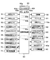
- FIG. 2 is a block diagram illustrating a configuration of an electric control unit of the vehicle air conditioner 1.
- the vehicle air conditioner 1 is applied to a hybrid vehicle that obtains driving force for traveling from an internal combustion engine EG (in other words, an engine) and a traveling electric motor.
- EG internal combustion engine
- the hybrid vehicle of the present embodiment is configured as a plug-in hybrid vehicle that can charge a battery 81 mounted on the vehicle with electric power supplied from an external power source (in other words, a commercial power source) when the vehicle is stopped.
- an external power source in other words, a commercial power source
- This plug-in hybrid vehicle charges the battery 81 with electric power supplied from an external power source when the vehicle stops before the vehicle starts running, so that the remaining power SOC of the battery 81 is predetermined as when the vehicle starts running.
- an operation mode is set in which the vehicle travels mainly by the driving force of the traveling electric motor.
- this operation mode is referred to as an EV operation mode.
- the driving mode is set to run mainly by the driving force of the engine EG.
- this operation mode is referred to as an HV operation mode.
- the EV operation mode is an operation mode in which the vehicle is driven mainly by the driving force output from the traveling electric motor.
- the engine EG is operated. Assist the electric motor for traveling. That is, the EV operation mode is an operation mode in which the driving force for driving output from the electric motor for driving is larger than the driving force for driving output from the engine EG.
- the EV operation mode is an operation mode in which the driving force ratio of the motor side driving force to the internal combustion engine side driving force (that is, motor side driving force / internal combustion engine side driving force) is greater than at least 0.5. .
- the HV operation mode is an operation mode in which the vehicle is driven mainly by the driving force output from the engine EG.
- the driving electric motor is operated to operate the engine EG.
- the HV operation mode is an operation mode in which the internal combustion engine side driving force is larger than the motor side driving force.
- the HV operation mode is an operation mode in which the driving force ratio is at least smaller than 0.5.
- the fuel consumption amount of the engine EG with respect to a normal vehicle that obtains driving force for vehicle travel only from the engine EG by switching between the EV operation mode and the HV operation mode in this way. This suppresses vehicle fuel efficiency.
- the switching between the EV operation mode and the HV operation mode and the control of the driving force ratio are controlled by the driving force control device 70.
- the driving force output from the engine EG is used not only for driving the vehicle but also for operating the generator 80.
- the electric power generated with the generator 80 and the electric power supplied from the external power supply can be stored in the battery 81, and the electric power stored in the battery 81 is not only a traveling electric motor but also a vehicle air conditioner. 1 can be supplied to various in-vehicle devices including an electric component device that constitutes 1.
- the vehicle air conditioner 1 performs air conditioning (for example, pre-air conditioning) in the vehicle interior using electric power supplied from an external power source when the vehicle is stopped before traveling, in addition to air conditioning in the vehicle interior using electric power supplied from the battery 81.
- air conditioning for example, pre-air conditioning
- the vehicle air conditioner 1 of the present embodiment includes the refrigeration cycle 10 shown in FIG. 1, the indoor air conditioning unit 30, the air conditioning control device 50 shown in FIG.
- the indoor air conditioning unit 30 is arranged inside the instrument panel (in other words, an instrument panel) at the foremost part of the vehicle interior, and a blower 32, an evaporator 15, a heater core 36, A PTC heater 37 or the like is accommodated.
- the casing 31 forms an air passage through which air blown into the passenger compartment (blowing air) flows, and is formed of a resin (for example, polypropylene) that has a certain degree of elasticity and is excellent in strength. ing. An air passage through which air flows is formed in the casing 31.
- a resin for example, polypropylene
- an inside / outside air switching box 20 is arranged as an inside / outside air switching unit that switches between the introduction of inside air (in other words, air in the passenger compartment) and outside air (in other words, outside air in the passenger compartment). ing.
- the inside / outside air switching box 20 has an inside air introduction port 21 and an outside air introduction port 22 formed therein.
- the inside air introduction port 21 introduces inside air into the casing 31.
- the outside air inlet 22 introduces outside air into the casing 31.
- inside / outside air switching box 20 is provided with inside / outside air switching door 23 for changing the air volume ratio between the amount of the inside air introduced into casing 31 and the amount of outside air.
- the inside / outside air switching door 23 is a suction mode switching unit that switches between the suction modes, and continuously adjusts the opening areas of the inside air introduction port 21 and the outside air introduction port 22.
- the inside / outside air switching door 23 constitutes an air volume ratio changing unit (in other words, an inside / outside air switching unit) that changes the air volume ratio between the air volume of the inside air introduced into the casing 31 and the air volume of the outside air.
- the inside / outside air switching door 23 is an outside air rate adjusting unit that adjusts the ratio of outside air to inside air and outside air introduced into the air passage (hereinafter referred to as outside air rate).
- the inside / outside air switching door 23 is driven by the electric actuator 62.
- the operation of the electric actuator 62 is controlled by a control signal output from the air conditioning controller 50.
- suction mode there are an all inside air mode, an all outside air mode, and an inside and outside air mixing mode.
- the inside air introduction port 21 is fully opened and the outside air introduction port 22 is fully closed to introduce the inside air into the air passage in the casing 31.
- the outside air mode the inside air introduction port 21 is fully closed and the outside air introduction port 22 is fully opened to introduce outside air into the air passage in the casing 31.
- the inside air and the outside air are introduced into the air passage in the casing 31. Change the ratio continuously.
- a blower 32 that blows the air sucked through the inside / outside air switching box 20 toward the vehicle interior is disposed on the downstream side of the air flow of the inside / outside air switching box 20.
- the blower 32 is an air volume adjusting unit that adjusts the air volume of the air flowing through the air passage in the casing 31.
- the blower 32 is an electric blower that drives a fan with an electric motor, and the number of rotations (in other words, the blowing capacity) is controlled by a control voltage output from the air conditioning control device 50. Therefore, this electric motor constitutes a blowing capacity changing unit of the blower 32.
- the fan of the blower 32 is a centrifugal multiblade fan (for example, a sirocco fan).
- the fan is disposed in the air passage, and blows the inside air from the inside air introduction port 21 and the outside air from the outside air introduction port 22 to the air passage.
- the evaporator 15 is arranged on the downstream side of the air flow of the blower 32.
- the evaporator 15 is disposed over the entire air passage.
- the evaporator 15 functions as a cooling unit (in other words, a heat exchanging unit) that cools the air blown into the vehicle interior by exchanging heat between the refrigerant flowing through the inside and the air blown from the blower 32.
- the evaporator 15 constitutes a vapor compression refrigeration cycle 10 together with the compressor 11, the condenser 12, the gas-liquid separator 13, the expansion valve 14, and the like.
- the compressor 11 is arranged in the engine room, sucks refrigerant in the refrigeration cycle 10, compresses and discharges the refrigerant,
- the fixed capacity type compression mechanism 11a having a fixed capacity is configured as an electric compressor that is driven by an electric motor 11b.
- the electric motor 11 b is an AC motor whose rotation speed is controlled by an AC voltage output from the inverter 61.
- the inverter 61 outputs an AC voltage having a frequency corresponding to the control signal output from the air conditioning control device 50. And the refrigerant
- the condenser 12 is disposed in the engine room and dissipates the refrigerant discharged from the compressor 11 by exchanging heat between the refrigerant flowing through the inside and the outside air blown from the blower fan 12a as an outdoor blower. It is an outdoor heat exchanger (in other words, a radiator) that is allowed to condense.
- the blower fan 12a is an electric blower in which the operation rate, that is, the rotation speed (in other words, the amount of air to be blown) is controlled by the control voltage output from the air conditioning control device 50.
- the gas-liquid separator 13 is a receiver that gas-liquid separates the refrigerant condensed in the condenser 12 to store surplus refrigerant and flows only the liquid-phase refrigerant downstream.
- the expansion valve 14 is a decompression unit that decompresses and expands the liquid-phase refrigerant that has flowed out of the gas-liquid separator 13.
- the evaporator 15 is an indoor heat exchanger that evaporates the low-pressure refrigerant decompressed and expanded by the expansion valve 14 and exerts an endothermic effect on the refrigerant. Thereby, the evaporator 15 functions as a cooling heat exchanger that cools and dehumidifies the air blown into the passenger compartment.
- a heating passage 33 and a bypass passage 34 for flowing the air after passing through the evaporator 15 are formed in parallel.
- a heater core 36 and a PTC heater 37 for heating the air after passing through the evaporator 15 are arranged in this order in the air flow direction.
- a mixing space 35 for mixing the air flowing out of the heating passage 33 and the bypass passage 34 is formed on the downstream side of the air passage of the heating passage 33 and the bypass passage 34.
- the heater core 36 is a heat exchanger for heating (in other words, an air heating unit) that heats air that has passed through the evaporator 15 by using engine cooling water (hereinafter simply referred to as cooling water) for cooling the engine EG as a heat medium.
- the engine EG is a cooling water heating unit (in other words, a heat medium heating unit) that heats the cooling water.
- the heater core 36 and the engine EG are connected by a cooling water pipe, and the cooling water circuit 40 in which the cooling water circulates between the heater core 36 and the engine EG is configured.
- the cooling water circuit 40 is provided with a cooling water pump 40 a for circulating the cooling water.
- the cooling water pump 40a is an electric water pump whose rotation speed (in other words, cooling water circulation flow rate) is controlled by a control voltage output from the air conditioning control device 50.
- the cooling water pump 40 a is a flow rate adjusting unit that adjusts the flow rate of the cooling water flowing through the heater core 36.
- the cooling water of the cooling water circuit 40 is also used for cooling the automatic transmission fluid (ie, ATF).
- ATF automatic transmission fluid
- the PTC heater 37 has a PTC element (in other words, a positive temperature coefficient thermistor).
- the PTC heater 37 generates heat when electric power is supplied to the PTC element, and serves as an auxiliary heater that heats air after passing through the heater core 36. It is. Note that the power consumption required to operate the PTC heater 37 of the present embodiment is less than the power consumption required to operate the compressor 11 of the refrigeration cycle 10.
- the PTC heater 37 is composed of a plurality (three in this embodiment) of PTC elements 37a, 37b, and 37c.
- the positive side of each PTC element 37a, 37b, 37c is connected to the battery 81 side, and the negative side is connected to the ground side via a switch element.
- the switch element switches between the energized state (in other words, the ON state) and the non-energized state (in other words, the OFF state) of each PTC element.
- the operation of the switch element is controlled by a control signal output from the air conditioning control device 50.
- the air-conditioning control device 50 controls the operation of the switch element so as to independently switch between the energized state and the non-energized state of each PTC element 37a, 37b, 37c. And the heating capacity of the PTC heater 37 as a whole can be changed.
- the bypass passage 34 is an air passage for guiding the air after passing through the evaporator 15 to the mixing space 35 without passing through the heater core 36 and the PTC heater 37. Accordingly, the temperature of the air mixed in the mixing space 35 varies depending on the air volume ratio of the air passing through the heating passage 33 and the air passing through the bypass passage 34.
- An air mix door 39 that continuously changes the air pressure is disposed.
- the air mix door 39 constitutes a temperature adjusting unit that adjusts the air temperature in the mixing space 35.
- the air temperature in the mixing space 35 is the temperature of the air blown into the vehicle interior.
- the air mix door 39 includes a common rotating shaft driven by a common electric actuator 63 and a plate-like door main body connected to the common rotating shaft. It consists of a so-called cantilever door.
- the operation of the electric actuator 63 for the air mix door is controlled by a control signal output from the air conditioning controller 50.
- air outlets 24 to 26 for blowing out temperature-adjusted air from the mixing space 35 to the vehicle interior that is the air-conditioning target space are arranged.
- a face air outlet 24, a foot air outlet 25, and a defroster air outlet 26 are provided.
- the face air outlet 24 is an upper body side air outlet that blows air-conditioned air toward the upper body of the passenger in the passenger compartment.
- the foot air outlet 25 is a foot side air outlet that blows air-conditioned air toward the feet of the occupant.
- the defroster air outlet 26 is a window glass side air outlet that blows conditioned air toward the inner surface of the front window glass W of the vehicle.
- the face door 24a for adjusting the opening area of the face air outlet 24 and the opening area of the foot air outlet 25 are adjusted.
- the defroster door 26a which adjusts the opening area of the foot door 25a to perform and the defroster blower outlet 26 is arrange
- the face door 24a, the foot door 25a, and the defroster door 26a constitute a blowing mode door (in other words, a blowing mode switching unit) for switching the blowing mode, and the blowing mode door is driven via a link mechanism (not shown). It is connected to the electric actuator 64 and is rotated in conjunction with it. The operation of the electric actuator 64 is also controlled by a control signal output from the air conditioning controller 50.
- face mode There are face mode, bi-level mode, foot mode and foot defroster mode.
- the face mode is abbreviated as FACE
- the foot mode is abbreviated as FOOT
- the bi-level mode is abbreviated as B / L.
- the face air outlet 24 is fully opened and air is blown out from the face air outlet 24 toward the upper body of the passenger in the passenger compartment.
- both the face air outlet 24 and the foot air outlet 25 are opened, and air is blown out toward the upper body and the feet of the passengers in the passenger compartment.
- the foot air outlet 25 is fully opened and the defroster air outlet 26 is opened by a small opening, and air is mainly blown out from the foot air outlet 25.
- the foot defroster mode the foot outlet 25 and the defroster outlet 26 are opened to the same extent, and air is blown out from both the foot outlet 25 and the defroster outlet 26.
- the passenger can also enter the defroster mode by manually operating the defroster switch 60c of the operation panel 60 shown in FIG.
- the defroster outlet 26 is fully opened, and air is blown out from the defroster outlet 26 to the inner surface of the vehicle front window glass.
- the bi-level mode, foot mode, foot defroster mode and defroster mode are non-face modes.
- the vehicle air conditioner 1 of this embodiment includes an electric heat defogger (not shown).
- the electric heat defogger is a heating wire disposed inside or on the surface of the vehicle interior window glass, and is a window glass heating unit that prevents fogging or window fogging by heating the window glass.
- the operation of the electric heat defogger can be controlled by a control signal output from the air conditioning controller 50.
- the vehicle air conditioner 1 includes a seat air conditioner 90 shown in FIG.
- the seat air conditioner 90 is an auxiliary heating unit that increases the surface temperature of the seat on which the occupant sits.
- the seat air conditioner 90 is a seat heating unit that is configured by a heating wire embedded in the seat surface and generates heat when supplied with electric power.
- the air-conditioning unit 30 operates to compensate for the passenger's feeling of heating.
- the operation of the seat air conditioner 90 is controlled by a control signal output from the air conditioner control apparatus 50, and is controlled so as to increase the surface temperature of the seat to about 40 ° C. during operation.
- the vehicle air conditioner 1 may include a seat blower, a steering heater, and a knee radiation heater.
- the seat blower is a blower that blows air from the inside of the seat toward the passenger.
- the steering heater is a steering heating unit that heats the steering with an electric heater.
- the knee radiant heater is a heating unit that radiates heat source light, which is a heat source of radiant heat, toward an occupant's knee. The operation of the seat blower, the steering heater, and the knee radiation heater can be controlled by a control signal output from the air conditioning controller 50.
- the air conditioning control device 50 (in other words, the air conditioning control unit), the driving force control device 70 (in other words, the driving force control unit), and the power control device 71 (in other words, the power control unit) include a CPU, a ROM, a RAM, and the like. It consists of a known microcomputer and its peripheral circuits. The electric control unit performs various calculations and processes based on the control program stored in the ROM, and controls the operation of various devices connected to the output side.
- the driving side of the driving force control device 70 is connected to various engine components constituting the engine EG and a traveling inverter for supplying an alternating current to the traveling electric motor.
- a starter for starting the engine EG a fuel injection valve for supplying fuel to the engine EG (in other words, an injector) drive circuit (all not shown), and the like are connected. .
- a sensor group for various engine controls such as a voltmeter, an ammeter, an accelerator opening sensor, an engine speed sensor, and a vehicle speed sensor (all not shown) are connected to the input side of the driving force control device 70.
- the voltmeter detects a terminal voltage VB of the battery 81.
- the ammeter detects the current ABin flowing into the battery 81 or the current ABout flowing from the battery 81.
- the accelerator opening sensor detects the accelerator opening Acc.
- the engine speed sensor detects the engine speed Ne.
- the vehicle speed sensor detects the vehicle speed Vv.
- the blower 32 On the output side of the air conditioning control device 50, the blower 32, the inverter 61 for the electric motor 11 b of the compressor 11, the blower fan 12 a, various electric actuators 62, 63, 64, the PTC heater 37, the cooling water pump 40 a, the seat air conditioner 90 etc. are connected.
- an inside air sensor 51 On the input side of the air conditioning controller 50, an inside air sensor 51, an outside air sensor 52, a solar radiation sensor 53, a discharge temperature sensor 54, a discharge pressure sensor 55, an evaporator temperature sensor 56, a cooling water temperature sensor 58, and a window surface humidity sensor 59.
- Various air conditioning control sensor groups such as the above are connected.
- the inside air sensor 51 is an inside air temperature detection unit that detects a vehicle interior temperature Tr.
- the outside air sensor 52 is an outside air temperature detecting unit that detects the outside air temperature Tam.
- the solar radiation sensor 53 is a solar radiation amount detection unit that detects the solar radiation amount Ts in the passenger compartment.
- the discharge temperature sensor 54 is a discharge temperature detecting unit that detects the refrigerant temperature Td discharged from the compressor 11.
- the discharge pressure sensor 55 is a discharge pressure detection unit that detects the refrigerant discharge pressure Pd of the compressor 11.
- the evaporator temperature sensor 56 is an evaporator temperature detector that detects a blown air temperature (hereinafter referred to as an evaporator temperature TE) that is a temperature of air blown from the evaporator 15.
- the coolant temperature sensor 58 is a coolant temperature detector that detects the coolant temperature Tw of coolant that has flowed out of the engine EG.
- the evaporator temperature sensor 56 of this embodiment specifically detects the heat exchange fin temperature of the evaporator 15.
- a temperature detector that detects the temperature of other parts of the evaporator 15 may be adopted, or a temperature detector that directly detects the temperature of the refrigerant itself flowing through the evaporator 15 is adopted. May be.
- the window surface humidity sensor 59 is a humidity detecting unit that detects near-window humidity.
- the humidity near the window is the relative humidity of the air in the passenger compartment near the window glass in the passenger compartment.
- operation signals are input from various air conditioning operation switches provided on the operation panel 60 disposed in the vicinity of the instrument panel in the front of the passenger compartment.
- Various air conditioning operation switches provided on the operation panel 60 are manual operation units for manually setting the operation of the air conditioning unit 30.
- various air conditioning operation switches provided on the operation panel 60 include an air conditioner switch 60a, an auto switch, a suction mode changeover switch, a blowout mode changeover switch 60b, a defroster switch 60c, an air volume setting switch 60d, a vehicle interior temperature.
- a setting switch 60e, an economy switch 60f, a display unit 60g for displaying the current operating state of the vehicle air conditioner 1, and the like are provided.
- the air conditioner switch 60a is a compressor operation setting unit that switches between starting and stopping of the compressor 11 by the operation of the passenger.
- the air conditioner switch 60a is provided with an air conditioner indicator that is turned on or off according to the operating state of the air conditioner switch 60a.
- the auto switch is an automatic control setting unit that sets or cancels the automatic control of the vehicle air conditioner 1 by the operation of the passenger.
- the blowing mode switching switch 60b is a blowing mode switching unit that switches between the face mode, the bi-level mode, the foot mode, and the foot defroster mode.
- the defroster switch 60c is a defroster mode setting unit that sets the defroster mode by the operation of the passenger.
- the blowing mode changeover switch 60 b and the defroster switch 60 c are anti-fogging operation units for outputting a command for improving the anti-fogging property of the window by the air conditioning unit 30 to the air conditioning control device 50.
- the air volume setting switch 60d is an air volume setting unit for manually setting the air volume of the blower 32.
- the vehicle interior temperature setting switch 60e is a target temperature setting unit that sets the vehicle interior target temperature Tset by the operation of the passenger.
- Economy switch 60f is a switch that prioritizes the reduction of environmental load. By turning on the economy switch 60f, the operation mode of the vehicle air conditioner 1 is set to an economy mode in which priority is given to power saving of the air conditioning.
- the economy switch 60f is a power saving priority mode setting unit.
- the air conditioning control device 50 and the driving force control device 70 are configured to be electrically connected to communicate with each other. Thereby, based on the detection signal or operation signal input into one control apparatus, the other control apparatus can also control the operation
- the driving force control device 70 receives a request signal for requesting the operation of the engine EG from the air conditioning control device 50, the driving force control device 70 determines whether or not the engine EG needs to be operated, and operates the engine EG according to the determination result. Control.
- the air conditioning control device 50 includes an electric power control device 71 that determines power to be distributed to various electric devices in the vehicle according to the power supplied from the power supply outside the vehicle or the power stored in the battery 81. It is connected to the.
- the air conditioning control device 50 of the present embodiment receives an output signal output from the power control device 71 (for example, data indicating air conditioning use permission power permitted to be used for air conditioning).
- the air-conditioning control device 50 and the driving force control device 70 are configured such that a control unit that controls various devices to be controlled connected to the output side is integrally configured.
- the configuration (for example, hardware and software) that controls the operation of each control target device constitutes a control unit that controls the operation of each control target device.
- the configuration that controls the operation of the blower 32, which is the blower unit, and controls the blower capability of the blower 32 constitutes the blower capability control unit 50a.
- the configuration for controlling the refrigerant discharge capacity of the compressor 11 by controlling the frequency of the AC voltage output from the inverter 61 connected to the electric motor 11b of the compressor 11 is the compressor control unit 50b. Is configured.
- the structure which controls switching of the suction mode among the air-conditioning control apparatus 50 comprises the suction mode switching part 50c.
- the structure which controls switching of the blowing mode among the air-conditioning control apparatuses 50 comprises the blowing mode switching part 50d.
- the structure which transmits / receives a control signal with the driving force control apparatus 70 in the air-conditioning control apparatus 50 constitutes a request signal output unit.
- a configuration for transmitting / receiving control signals to / from the air-conditioning control device 50 in the driving force control device 70 and determining whether or not the engine EG needs to be operated according to an output signal from the request signal output unit or the like (in other words, determining whether or not to operate) Part) constitutes a signal communication part.
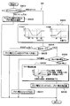
- FIG. 3 is a flowchart showing a control process as a main routine of the vehicle air conditioner 1 of the present embodiment.
- the operation switch of the vehicle air conditioner 1 is turned on while power is supplied from the battery 81 or an external power source to various in-vehicle devices including the electric components constituting the vehicle air conditioner 1. Will start.
- each control section in FIG. 3 to FIG. 10 constitutes various function realization units that the air conditioning control device 50 has.
- initialization of flags, timers, etc., and initial positioning of the stepping motor constituting the electric actuator described above is performed.
- this initialization some of the flags and calculation values that are stored at the end of the previous operation of the vehicle air conditioner 1 are maintained.
- Specific operation signals include a vehicle interior target temperature Tset set by a vehicle interior temperature setting switch, a suction mode switch setting signal, and the like.
- a vehicle environmental state signal used for air conditioning control that is, a detection signal of the above-described sensor groups 51 to 58, a power state signal indicating a power supply state from an external power source, and the like are read.
- the power status signal indicates a state in which power can be supplied from the external power source to the vehicle (plug-in state)
- the external power source flag is turned on and power cannot be supplied from the external power source to the vehicle (plug-out state) )
- the external power flag is turned off.
- S4 comprises the target blowing temperature determination part.
- the target blowing temperature TAO is calculated by the following formula F1.
- TAO Kset ⁇ Tset ⁇ Kr ⁇ Tr ⁇ Kam ⁇ Tam ⁇ Ks ⁇ Ts + C... F1
- Tset is the vehicle interior set temperature set by the vehicle interior temperature setting switch
- Tr is the vehicle interior temperature detected by the internal air sensor 51 (in other words, the internal air temperature)
- Tam is the external air temperature detected by the external air sensor 52.
- Ts is the amount of solar radiation detected by the solar radiation sensor 53.
- Kset, Kr, Kam, Ks are control gains
- C is a correction constant.
- the target blowout temperature TAO corresponds to the amount of heat that the vehicle air conditioner 1 needs to generate in order to keep the passenger compartment at a desired temperature, and the air conditioning load required for the vehicle air conditioner 1 (air conditioning heat). Load).
- control states of various devices connected to the air conditioning control device 50 are determined.
- the target opening degree of the air mix door 39 is calculated based on the target outlet temperature TAO, the evaporator temperature TE detected by the evaporator temperature sensor 56, and the cooling water temperature Tw. Specifically, first, a temporary air mix opening degree SWdd is calculated by the following formula F2.
- the air mix opening SW is determined with reference to a control map stored in the air conditioning control device 50 in advance. In this control map, the air mix opening SW is determined so as to be substantially proportional to the provisional air mix opening SWdd.
- the blowing capacity of the blower 32 (specifically, the voltage applied to the electric motor) is determined.
- the air volume of the air flowing through the air passage in the casing 31 is determined. Details of S6 will be described with reference to the flowchart of FIG.
- S601 it is determined whether or not the auto switch of the operation panel 60 is turned on. As a result, if it is determined that the auto switch is not turned on, in S602, the blower voltage that is a passenger-desired desired air volume manually set by the air volume setting switch 60d of the operation panel 60 is determined, and the process proceeds to S7. .
- the air volume setting switch 60d of the present embodiment can set five levels of air volume, Lo, M1, M2, M3, and Hi, and the blower voltage in the order of 4V, 6V, 8V, 10V, and 12V, respectively. Is determined to be high.
- the control map stored in the air conditioning controller 50 in advance based on the target blowing temperature TAO determined in S4 is referred to.
- the temporary blower voltage f (TAO) and the warm-up upper limit blower voltage f (water temperature) are determined.
- Temporary blower voltage f (TAO) is determined according to the air conditioning heat load.
- the temporary blower voltage f (TAO) is used as a candidate value for the blower voltage finally determined in S6.
- the blower voltage is a blower voltage applied to the electric motor of the blower 32.
- the control map for determining the temporary blower voltage f (TAO) in the present embodiment is configured such that the value of the temporary blower voltage f (TAO) with respect to the target blowing temperature TAO draws a bathtub-like curve.
- the air volume of the blower 32 is raised to a high level so that is near the maximum air volume.
- the temporary blower voltage f (TAO) is decreased so that the blower amount of the blower 32 is reduced according to the increase of the target blowing temperature TAO.
- the temporary blower voltage f (TAO) is decreased so that the air volume of the blower 32 is decreased according to the decrease in the target blowing temperature TAO.
- the temporary blower voltage f (TAO) is set to a low level so that the air volume of the blower 32 becomes low. Reduce. Thereby, the basic blower voltage corresponding to the air conditioning heat load is calculated.
- the temporary blower voltage f (TAO) is a value determined based on the target blowout temperature TAO.
- the temporary blower voltage f (TAO) is determined based on values determined based on the vehicle interior set temperature Tset, the internal air temperature Tr, the external air temperature Tam, and the solar radiation amount Ts.
- Temporary blower voltage f (TAO) is determined to a value (specifically, 4 to 12) corresponding to the air volume in the normal use range.
- the warm-up upper limit blower voltage f (water temperature) is the upper limit value of the blower voltage when the engine EG is warmed up (that is, when the coolant temperature Tw is low).
- the blower voltage correction value f (humidity near the window) is a blower voltage correction value corresponding to the possibility of fogging of the window glass.
- the warm-up upper limit blower voltage f (water temperature) is set to 0 in the low temperature range of the cooling water temperature Tw (in this embodiment, 40 ° C. or less). In the extremely high temperature range of the cooling water temperature Tw (in this embodiment, 65 ° C. or higher), the warm-up upper limit blower voltage f (water temperature) is set to 11. As the cooling water temperature Tw rises from the low temperature range to the high temperature range, the warm-up upper limit blower voltage f (water temperature) is raised in the range of 0 to 11.
- the control process proceeds to S605, and the blower voltage is calculated by the following formula F3.
- Blower voltage MIN ⁇ f (TAO), f (water temperature) ⁇ F3
- MIN ⁇ f (TAO), f (water temperature) ⁇ in Formula F3 means a smaller value of f (TAO) and f (water temperature).
- the blowing capacity of the blower 32 is appropriately adjusted according to the target blowing temperature TAO and the cooling water temperature Tw.
- the control process proceeds to S606, and it is determined whether or not the water flow to the heater core 36 is stopped. In other words, it is determined whether or not the flow rate of the cooling water flowing through the heater core 36 is a predetermined value or less.
- the cooling water valve is a flow rate adjusting unit that adjusts the flow rate of the cooling water flowing through the heater core 36.
- the control process proceeds to S607, and the blower voltage is determined to be the temporary blower voltage f (TAO).
- the blowing capacity of the blower 32 is appropriately adjusted according to the target blowing temperature TAO. That is, when the blowing mode is the face mode and water is passed through the heater core 36, the air volume control according to the cooling water temperature Tw is not performed.
- a control process progresses to S608 and determines a blower voltage correction amount.
- the target outlet temperature TAO determined in S4 the evaporator temperature TE detected by the evaporator temperature sensor 56, the vehicle interior temperature Tr detected by the inside air sensor 51, and the outside air sensor 52 are detected.
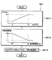
- the blower voltage correction amount is determined with reference to a control map stored in the air conditioning control device 50 in advance.
- the blower voltage correction amount is the amount of air blown into the passenger compartment so that the passenger is less likely to feel cold. Is used to keep low.
- the difference TAO-TE obtained by subtracting the evaporator temperature TE from the target outlet temperature TAO is large, and the difference Tr-Tam obtained by subtracting the outside air temperature Tam from the vehicle interior temperature Tr is small.
- the blower voltage correction amount is determined to be a large value.
- the blower voltage correction amount is determined to be 0 regardless of the value of TAO-TE.
- the blower voltage correction amount is determined to be 0. If 10 ° C ⁇ TAO-TE ⁇ 30 ° C or less, the TAO-TE As the value increases, the blower voltage correction amount is increased in the range of 0 to 1. If TAO-TE ⁇ 30 ° C., the blower voltage correction amount is determined to be 1.
- the blower voltage correction amount is determined as 0 if TAO-TE ⁇ 10 ° C., and the value of TAO-TE increases if 10 ° C ⁇ TAO-TE ⁇ 30 ° C. Accordingly, the blower voltage correction amount is increased in the range of 0 to 2, and if TAO-TE ⁇ 30 ° C., the blower voltage correction amount is determined to be 2.
- blower voltage is calculated by the following formula F4.
- Blower voltage f (TAO) ⁇ Blower voltage correction amount... F4
- blowing capacity of the blower 32 is corrected to be lower as the difference obtained by subtracting the evaporator temperature TE from the target blowing temperature TAO and the smaller difference obtained by subtracting the outside air temperature Tam from the vehicle interior temperature Tr are reduced.
- the blowing mode is the face mode and water is not passed through the heater core 36
- the amount of air blown into the passenger compartment is corrected to be lower as the passenger is more likely to feel cold due to the air blown into the passenger compartment. To do.
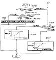
- the suction mode that is, the switching state of the inside / outside air switching box 20 is determined. Details of S7 will be described with reference to the flowchart of FIG. 5, first, in S701, it is determined whether or not the auto switch of the operation panel 60 is turned on. As a result, if it is determined that the auto switch is not turned on, the outside air introduction rate corresponding to the manual mode is determined in S702 to S704, and the control process proceeds to S8.
- the outside air rate is determined to be 0% in S703.
- the manual suction mode is the all outside air mode (in other words, the FRS mode)
- the outside air rate is determined to be 100% in S704.
- the outside air rate is a ratio of outside air to the introduced air (that is, outside air and inside air) introduced from the inside / outside air switching box 20 into the casing 31.
- the control process proceeds to S705, and based on the target blowing temperature TAO calculated in S4, whether the air conditioning operation state is the cooling operation or the heating operation is determined. judge. In the example of FIG. 5, when the target blowing temperature TAO is higher than 25 ° C., it is determined that the heating operation is performed, and in other cases, the cooling operation is determined.
- the control process proceeds to S706, the outside air rate is determined with reference to the control map stored in advance in the air conditioning control device 50 based on the target blowing temperature TAO, and the process proceeds to S8. .
- the outside air rate is reduced, and when the target blowing temperature TAO is high, the outside air rate is increased.
- the outside air rate is 0%
- TAO ⁇ 15 ° C. the outside air rate is 100%
- the target outlet temperature TAO is high.
- the outside air rate is increased in the range of 0 to 100%.
- the opening degree of the inside / outside air switching door 23 is changed according to the determined outside air rate. Specifically, when the outside air rate is set to 0%, the opening degree of the inside / outside air switching door 23 is controlled so that the suction mode becomes the all inside air mode. When the outside air rate is set to 100%, the opening degree of the inside / outside air switching door 23 is controlled so that the suction mode becomes the all outside air mode. When the outside air rate is set to be more than 0% and less than 100%, the opening degree of the inside / outside air switching door 23 is controlled so that the suction mode becomes the inside / outside air mixing mode.
- the control process proceeds to S707, and the control map stored in the air conditioning control device 50 in advance is referred to based on the near-window humidity detected by the window surface humidity sensor 59.
- the outside air rate is determined, and the process proceeds to S8.
- the outside air rate is reduced when the humidity near the window is low, and the outside air rate is increased when the humidity near the window is high.
- the outside air rate is 50%
- the outside air rate is 100%
- the higher the humidity in the vicinity of the window the larger the outside air rate in the range of 50 to 100%.
- the blowing mode that is, the switching state of the face door 24a, the foot door 25a, and the defroster door 26a is determined. Details of S8 will be described with reference to the flowchart of FIG.
- the face mode is determined.
- the bi-level mode is determined.
- the foot mode is determined.
- the foot defroster mode is determined.
- the manual suction mode is the defroster mode, the defroster mode is determined.
- the blowing mode is sequentially switched to the face mode, the bi-level mode, and the foot mode as the target blowing temperature TAO rises from the low temperature range to the high temperature range. Accordingly, it is easy to select the face mode mainly in summer, the bi-level mode mainly in spring and autumn, and the foot mode mainly in winter.
- a hysteresis width for preventing control hunting is set.
- the refrigerant discharge capacity of the compressor 11 (specifically, the rotational speed of the compressor 11) is determined.
- the determination of the compressor speed in S9 is not performed at every control cycle ⁇ in which the main routine of FIG. 3 is repeated, but at every predetermined control interval (1 second in this embodiment).
- a target outlet temperature TEO of the evaporator temperature TE from the indoor evaporator (evaporator 15) is determined.
- a temporary target blowing temperature f (TAO) is calculated with reference to a control map stored in advance in the air conditioning control device 50.
- the temporary target blowing temperature f (TAO) is set to 1 ° C. If TAO ⁇ 12 ° C., the temporary target blowing temperature f (TAO) is set to 10 ° C. If 4 ° C. ⁇ TAO ⁇ 12 ° C., the larger the target blowing temperature TAO, the larger the temporary target blowing temperature f (TAO) in the range of 1 to 10 ° C.
- the anti-fogging target blowing temperature f (the near-window humidity) is calculated with reference to a control map stored in advance in the air conditioning control device 50.
- the antifogging target blowing temperature f (the humidity near the window) is set to 10 ° C. If the humidity near the window ⁇ 95%, the target antifogging temperature f (the humidity near the window) is set to 1 ° C. If 85% ⁇ window vicinity humidity ⁇ 95%, the higher the window vicinity humidity, the lower the antifogging target blowing temperature f (window vicinity humidity) in the range of 10 to 1 ° C.
- the smaller one of the temporary target blowing temperature f (TAO) and the anti-fogging target blowing temperature f (the humidity near the window) is determined as the target blowing temperature TEO.
- the target blowing temperature TEO can be determined to be a small value, and the dehumidifying ability of the indoor evaporator (evaporator 15) can be increased.
- the rotational speed change amount ⁇ f with respect to the previous compressor rotational speed fn-1 is obtained. More specifically, a deviation En (TEO-TE) between the target blowing temperature TEO and the evaporator temperature TE is calculated, and a deviation change rate Edot (En) obtained by subtracting the previously calculated deviation En-1 from the previously calculated deviation En. -(En-1)) is calculated. Subsequently, using the deviation En and the deviation rate of change Edot, based on the fuzzy inference based on the membership function and rules stored in advance in the air-conditioning control device 50, the rotation with respect to the previous compressor speed fn-1 is performed. The number change amount ⁇ f is obtained.
- the rotational speed of the compressor can be increased and the dehumidifying ability of the indoor evaporator (evaporator 15) can be increased.
- the control process proceeds to S102, and the number of operating PTC heaters 37 is determined to be three.
- the control process proceeds to S103.
- the target outlet temperature TAO determined in S4 the evaporator temperature TE detected by the evaporator temperature sensor 56, the vehicle interior temperature Tr detected by the internal air sensor 51, and the outside air temperature detected by the outside air sensor 52.
- the number of PTC heaters 37 to be operated is determined with reference to a control map stored in the air conditioning control device 50 in advance.
- the number of operation of the PTC heater 37 is in the range of 0 to 3 as the difference between the target outlet temperature TAO and the evaporator temperature TE is larger and the difference between the passenger compartment temperature Tr and the outside air temperature Tam is larger.
- the number is decided with a large number.
- the fact that the air mix opening SW is not the maximum heating opening means that it is less necessary to heat the air in the heating passage 33, so there is less need to operate the number of PTC heaters 37. Obviously, the fact that the air mix opening SW is not the maximum heating opening means that it is less necessary to heat the air in the heating passage 33, so there is less need to operate the number of PTC heaters 37. Obviously, the fact that the air mix opening SW is not the maximum heating opening means that it is less necessary to heat the air in the heating passage 33, so there is less need to operate the number of PTC heaters 37. Become.
- the number of PTC heaters 37 to be operated is determined to be zero regardless of the value of the difference TAO-TE obtained by subtracting the evaporator temperature TE from the target blowing temperature TAO.
- TAO-TE ⁇ 10 ° C the number of operating PTC heaters 37 is determined to be 0, and if 10 ° C ⁇ TAO-TE ⁇ 30 ° C, TAO- As TE increases, the number of operating PTC heaters 37 is increased in the range of 0 to 2. If TAO-TE ⁇ 30 ° C., the number of operating PTC heaters 37 is determined to be two.
- the electric heat defogger For the electric heat defogger, if there is a high possibility of fogging on the window glass due to the humidity and temperature in the passenger compartment, or if the window glass is fogged, the electric heat defogger is activated.
- the request signal includes an engine EG operation request signal (in other words, an engine ON request signal), an EV / HV operation mode request signal, and the like.
- the cooling water is always at a high temperature because the engine is always operated during running. Therefore, in a normal vehicle, sufficient heating capacity can be exhibited by circulating cooling water through the heater core 36.
- the driving force for traveling the vehicle can be obtained from the traveling electric motor. Therefore, the operation of the engine EG may be stopped, and when the vehicle air conditioner 1 heats the vehicle interior, the temperature of the cooling water may not rise to a temperature sufficient as a heat source for heating. is there.
- the vehicle air conditioner 1 does not require the engine EG to operate in order to output the driving force for traveling.
- a request signal for requesting the operation of the engine EG is output to the driving force control device 70 that controls the driving force, and the cooling water temperature is increased to a temperature sufficient as a heat source for heating.
- S12 it is determined whether or not to operate the cooling water pump 40a of the cooling water circuit 40. Details of S12 will be described with reference to the flowchart of FIG. First, in S121, it is determined whether or not the cooling water temperature Tw is higher than the evaporator temperature TE that is the temperature of the air blown from the evaporator 15.
- the flow rate of the cooling water discharged from the cooling water pump 40a may be reduced more than usual. In other words, the flow rate of the cooling water discharged from the cooling water pump 40a may be set to a predetermined value or less.
- the control process proceeds to S122.
- S122 it is determined whether or not the blower 32 is operating. If it is determined in S122 that the blower 32 is not operating, the control process proceeds to S124, and it is determined to stop the cooling water pump 40a for power saving.
- a control process progresses to S123 and determines operating the cooling water pump 40a.
- the cooling water pump 40a is activated and the cooling water circulates in the cooling water circuit, so that the cooling water flowing through the heater core 36 and the air passing through the heater core 36 can be heat-exchanged to heat the air. it can.
- the seat air conditioner 90 it is determined whether or not the seat air conditioner 90 needs to be operated.
- the operating state of the seat air conditioner 90 is determined based on the control map stored in advance in the air conditioning controller 50 based on the target air temperature TAO determined in S5, the temporary air mix opening degree Sdd, and the outside air temperature Tam read in S2. Determined by reference.
- the air conditioner controller 50 controls the various devices 12a, 32, 37, 40a, 61, 62, 63, 64, 90 so that the control states determined in S5 to S13 described above are obtained. A control signal and a control voltage are output. Further, the request signal determined in S ⁇ b> 11 is transmitted from the suction mode switching unit 50 c (request signal output unit) to the driving force control device 70.
- the system waits for the control period ⁇ , and returns to S2 when it is determined that the control period ⁇ has elapsed.
- the control cycle ⁇ is 250 ms. This is because the air conditioning control in the passenger compartment does not adversely affect the controllability even if the control period is slower than the engine control or the like. As a result, it is possible to suppress a communication amount for air conditioning control in the vehicle and sufficiently secure a communication amount of a control system that needs to perform high-speed control such as engine control.
- the vehicle air conditioner 1 of this embodiment operates as described above, the air blown from the blower 32 is cooled by the evaporator 15.
- the cold air cooled by the evaporator 15 flows into the heating passage 33 and the bypass passage 34 according to the opening degree of the air mix door 39.
- the cold air that has flowed into the heating passage 33 is heated when passing through the heater core 36 and the PTC heater 37, and is mixed with the cold air that has passed through the bypass passage 34 in the mixing space 35. Then, the conditioned air whose temperature has been adjusted in the mixing space 35 is blown out from the mixing space 35 into the vehicle compartment via each outlet.
- the temperature of the heater core 36 decreases with time, and the difference between the target blowing temperature TAO and the actual blowing temperature increases.
- the actual blowing temperature is approximately the same as the evaporator temperature TE.
- the blowing mode is the face mode
- air having a temperature lower than the target blowing temperature TAO is blown out toward the upper body of the occupant, so that the occupant can easily feel cold.
- blower power consumption can be reduced by correcting the blower voltage to be low, the fuel consumption can be improved.
- the higher the target blowout temperature TAO the greater the deviation from the blowout air temperature that the occupant wants, and the greater the possibility that the occupant will feel cold.
- the higher the target blowing temperature TAO the lower the blower voltage is corrected. Therefore, the higher the target blowing temperature TAO, the less the amount of air blown toward the passenger's upper body.
- the blower voltage is corrected to be lower as the solar radiation amount Ts is smaller. Therefore, the smaller the solar radiation amount Ts, the smaller the air volume blown toward the upper body of the occupant.
- the temperature of the blown air may be extremely lowered.
- the air volume can be made smaller than the normal use area.
- the blower voltage can be set to a value smaller than 4 to 12 V in the normal use range. Thereby, it can suppress that the air of a very low temperature is blown off by a passenger
- the temperature of the heater core 36 when the ignition switch of the vehicle is turned on and the temperature of the cooling water inside the heater core 36 are approximately the same as the outside air temperature, but the heater core 36 was cooled by the evaporator 15. Cold air flows in. At this time, if the water flow to the heater core 36 is stopped, the temperature of the heater core 36 falls below the outside air temperature. When the water flow to the heater core 36 is stopped, since the air volume is smaller than that in the normal use range, it is possible to suppress the temperature of the heater core 36 from decreasing immediately after turning on the ignition switch of the vehicle, and the passenger feels cold. This can be suppressed.
- the cabin temperature at the start of air conditioning increases as the amount of solar radiation increases and is exposed to longer periods of solar radiation.
- the temperature of the instrument panel also rises, but since the air conditioning duct connected to the face outlet 24 (hereinafter referred to as the face duct) is inside the instrument panel, the temperature of the face duct also rises. Therefore, even if the temperature of the blown air is low at the outlet of the indoor air conditioning unit 30, the blown air is warmed by the face duct, so that the passenger does not feel too cold. On the contrary, it feels hot when the air volume is lowered.
- the degree of decrease in air volume can be reduced, and fuel efficiency can be improved while maintaining passenger comfort.
- the temperature of the face duct can be accurately estimated from the vehicle interior temperature Tr detected by the inside air sensor 51.
- the control device 50 controls the operation of the blower 32 by determining the amount of air flowing through the air passage in the casing 31 based on the target blowing temperature TAO. Then, when the blowing mode is the face mode and the flow rate of the cooling water flowing through the heater core 36 is a predetermined value or less, the control device 50 corrects the air volume of the air flowing through the air passage in the casing 31 to the decreasing side.
- control device 50 increases the correction amount toward the decrease side of the air volume of the air flowing through the air passage in the casing 31 as the target blowing temperature TAO is higher.
- the higher the target blowing temperature TAO the greater the difference between the blowing temperature that the occupant wants and the actual blowing temperature, and the more likely the occupant feels cold. Therefore, the occupant is prevented from feeling cold by suppressing the flow rate of the air blown out toward the occupant's upper body.
- control device 50 performs the air passage when the face door 24a and the foot door 25a are executing the face mode and the flow rate of the cooling water flowing through the heater core 36 is equal to or less than a predetermined value.
- the air volume of the air flowing through the air is corrected to an air volume smaller than the normal use range.
- the amount of blown air is made smaller than the normal use area, so Can suppress feeling.
- the blown air flow rate smaller than that in the normal use range, it is possible to suppress the cool air cooled by the evaporator 15 from flowing into the heater core 36, and thus the temperature of the heater core 36 is prevented from being lowered. it can.
- control device 50 decreases the correction amount to the air volume reduction side of the air flowing through the air passage as the vehicle interior temperature Tr is higher than the outside air temperature Tam.
- the inside air sensor 51 is preferably arranged in the instrument panel. This is because the temperature of the air conditioning duct can be accurately estimated from the passenger compartment temperature Tr detected by the inside air sensor 51.
- control device 50 increases the difference in the air flowing through the air passage as the difference between the target blowing temperature TAO and the evaporator temperature TE, which is the temperature of the air blown from the evaporator 15, increases. Increase the amount of correction to reduce the airflow.
- control device 50 operates the PTC heater 37 (auxiliary heating unit) when the difference obtained by subtracting the evaporator 15 from the target blowing temperature TAO is equal to or greater than a predetermined value.
- the PTC heater when the difference obtained by subtracting the evaporator 15 from the target blowing temperature TAO is large. Since the 37 is operated, the degree to which the occupant feels cold can be reduced.
- the blower voltage correction amount is determined based on the target outlet temperature TAO, the evaporator temperature TE, the passenger compartment temperature Tr, and the outside air temperature Tam in S608.
- the blower voltage correction amount is determined based on the solar radiation amount Ts, the vehicle interior temperature Tr, and the outside air temperature Tam in S608.
- the blower voltage correction amount is determined to be larger as the solar radiation amount Ts is larger and the difference Tr ⁇ Tam obtained by subtracting the outside air temperature Tam from the passenger compartment temperature Tr is smaller.
- the blower voltage correction amount is determined to be 0 regardless of the solar radiation amount Ts.
- the blower voltage correction amount is determined as 1 if Ts ⁇ 300 W / m 2, and the solar radiation amount Ts increases if 300 W / m 2 ⁇ Ts ⁇ 1000 W / m 2. Accordingly, the blower voltage correction amount is decreased in the range of 1 to 0. If Ts ⁇ 1000 W / m 2, the blower voltage correction amount is determined to be zero.
- the blower voltage correction amount is determined to be 2 if Ts ⁇ 300 W / m 2, and the blower voltage increases as the solar radiation amount Ts increases if 300 W / m 2 ⁇ Ts ⁇ 1000 W / m 2.
- the correction amount is decreased in the range of 2 to 0. If Ts ⁇ 1000 W / m 2, the blower voltage correction amount is determined to be 0.
- the blowing mode is the face mode and water is not passed through the heater core 36
- the vehicle is more likely to feel cold due to the air blown into the passenger compartment. Correct the volume of air blown into the room. Therefore, the same operational effects as those of the first embodiment can be obtained.
- the control device 50 increases the correction amount toward the decrease side of the air volume of the air flowing through the air passage as the solar radiation amount Ts decreases. According to this, in view of the fact that the smaller the amount of solar radiation Ts, the more easily the occupant feels cold against the cold wind, the smaller the amount of solar radiation Ts, the smaller the flow rate of air blown toward the upper body of the occupant. , The passengers can be prevented from feeling cold.
- the air conditioning control device 50 linearly changes the value of the blower voltage correction amount in S6 according to the difference obtained by subtracting the evaporator temperature TE from the target blowing temperature TAO or the solar radiation amount Ts. Correct the voltage.
- the value of the blower voltage correction amount may be changed non-linearly according to the difference obtained by subtracting the evaporator temperature TE from the target blowing temperature TAO or the solar radiation amount Ts.
- the heater core flow rate FW is adjusted by adjusting the rotational speed of the cooling water pump 40a.
- the heater core flow rate FW may be adjusted by adjusting the opening degree of the cooling water valve provided in the cooling water circuit 40.
- the cooling water valve is a flow rate adjusting unit that adjusts the flow rate of the cooling water flowing through the heater core 36.
- the vehicle air conditioner 1 may be applied to the vehicle.
- the engine EG is used as a drive source of the generator 80, the generated power is stored in the battery 81, and the driving power is obtained from a traveling electric motor that operates by being supplied with the power stored in the battery 81.
- the vehicle air conditioner 1 may be applied to a so-called serial-type hybrid vehicle that travels on the road.
- the vehicle air conditioner 1 may be applied to an electric vehicle that obtains a driving force for vehicle traveling only from the traveling electric motor without providing the engine EG.
- an electric heater such as a PTC heater can be used as the cooling water heating unit for heating the cooling water.
- the compressor 11 can be a belt-driven compressor that is driven by an engine belt by the driving force of the engine EG.
Landscapes
- Engineering & Computer Science (AREA)
- Physics & Mathematics (AREA)
- Thermal Sciences (AREA)
- Mechanical Engineering (AREA)
- Chemical & Material Sciences (AREA)
- Combustion & Propulsion (AREA)
- Air-Conditioning For Vehicles (AREA)
Abstract
加熱用熱交換器を流れる熱媒体の流量が少ないときに乗員が寒さを感じることを抑制可能な車両用空調装置を提供する。車両用空調装置は、ケーシング(31)、加熱用熱交換器(36)、流量調整部(40a)、風量調整部(32)、吹出モード切替部(24a、25a)、および制御部(50)を備える。ケーシングは、空気通路、フェイス吹出口(24)、およびフット吹出口(25)を有する。加熱用熱交換器は、エンジン(EG)を冷却する熱媒体と空気とを熱交換させて空気を加熱する。流量調整部は、加熱用熱交換器を流れる熱媒体の流量を調整する。風量調整部は、空気通路を流れる空気の風量を調整する。吹出モード切替部は、フェイスモードと非フェイスモードとを切り替える。制御部は、空気通路を流れる空気の風量を目標吹出温度(TAO)に基づいて決定して風量調整部の作動を制御し、吹出モード切替部がフェイスモードを実行しており且つ加熱用熱交換器を流れる熱媒体の流量が所定値以下である場合、空気通路を流れる空気の風量を減少側に補正する。
Description
本出願は、当該開示内容が参照によって本出願に組み込まれた、2016年2月8日に出願された日本特許出願2016-022152号を基にしている。
本開示は、車両に用いられる空調装置に関する。
従来、特許文献1には、エンジン冷却水の温度が低い時、ヒータコアへの冷却水の流通を遮断することによってエンジンの暖機を促進させる車両用空調装置が記載されている。
ヒータコアは、エンジン冷却水と車室内へ送風される空気とを熱交換させて車室内へ送風される空気を加熱する熱交換器である。
この従来技術では、エンジン冷却水の温度が低い時、エンジンの熱がヒータコアで外部に放熱されることが抑制されるので、エンジン冷却水の温度を早期に上昇させてエンジンの暖機を促進させることができる。
しかしながら、上記従来技術では、エンジン冷却水の温度が低い時、ヒータコアへの冷却水の流通を遮断するので、車室内へ送風される空気がヒータコアで加熱されることなく車室内に吹き出されてしまい、乗員が寒さを感じるおそれがある。
本開示は上記点に鑑みて、加熱用熱交換器を流れる熱媒体の流量が少ないときに乗員が寒さを感じることを抑制可能な車両用空調装置を提供することを目的とする。
本開示の車両用空調装置は、ケーシング、加熱用熱交換器、流量調整部、風量調整部、吹出モード切替部、および制御部を備える。
ケーシングは、車室内空間へ吹き出される空気が流れる空気通路と、空気通路から乗員の上半身へ向けて空気を吹き出すためのフェイス吹出口と、空気通路から乗員の足元へ向けて空気を吹き出すためのフット吹出口と、を有している。加熱用熱交換器は、ケーシング内に配置され、エンジンを冷却する熱媒体と空気とを熱交換させて空気を加熱する。流量調整部は、加熱用熱交換器を流れる熱媒体の流量を調整する。風量調整部は、空気通路を流れる空気の風量を調整する。吹出モード切替部は、フェイス吹出口を開いてフット吹出口を閉じるフェイスモードと、フット吹出口を開ける非フェイスモードとを切り替える。制御部は、空気通路を流れる空気の風量を目標吹出温度に基づいて決定して風量調整部の作動を制御し、吹出モード切替部がフェイスモードを実行しており且つ加熱用熱交換器を流れる熱媒体の流量が所定値以下である場合、空気通路を流れる空気の風量を減少側に補正する。
これによると、加熱用熱交換器を流れる熱媒体の流量が少ない場合、乗員の上半身へ向けて吹き出される空気の流量を少なく抑えることができる。そのため、エンジンの暖機時に燃費を向上するために加熱用熱交換器を流れる熱媒体の流量を少なくしても、乗員が寒さを感じることを抑制できる。
本開示についての上記目的およびその他の目的、特徴や利点は、添付の図面を参照しながら下記の詳細な記述により、より明確になる。
以下に、図面を参照しながら本開示を実施するための複数の実施形態を説明する。各実施形態において先行する実施形態で説明した事項に対応する部分には同一の参照符号を付して重複する説明を省略する場合がある。各実施形態において構成の一部のみを説明している場合は、構成の他の部分については先行して説明した実施形態と同様とする。各実施形態で具体的に説明している部分の組合せばかりではなく、特に組合せに支障が生じなければ、実施形態同士を部分的に組み合せることも可能である。
(第1実施形態)
以下、実施形態について図に基づいて説明する。図1は、本実施形態の車両用空調装置1の全体構成図であり、図2は、車両用空調装置1の電気制御部の構成を示すブロック図である。本実施形態では、車両用空調装置1は、内燃機関EG(換言すればエンジン)および走行用電動モータから車両走行用の駆動力を得るハイブリッド車両に適用されている。
以下、実施形態について図に基づいて説明する。図1は、本実施形態の車両用空調装置1の全体構成図であり、図2は、車両用空調装置1の電気制御部の構成を示すブロック図である。本実施形態では、車両用空調装置1は、内燃機関EG(換言すればエンジン)および走行用電動モータから車両走行用の駆動力を得るハイブリッド車両に適用されている。
本実施形態のハイブリッド車両は、車両停車時に外部電源(換言すれば商用電源)から供給された電力を、車両に搭載されたバッテリ81に充電可能なプラグインハイブリッド車両として構成されている。
このプラグインハイブリッド車両は、車両走行開始前の車両停車時に外部電源から供給された電力をバッテリ81に充電しておくことによって、走行開始時のようにバッテリ81の蓄電残量SOCが予め定めた走行用基準残量以上になっているときには、主に走行用電動モータの駆動力によって走行する運転モードとなる。以下、この運転モードをEV運転モードという。
一方、車両走行中にバッテリ81の蓄電残量SOCが走行用基準残量よりも低くなっているときには、主にエンジンEGの駆動力によって走行する運転モードとなる。以下、この運転モードをHV運転モードという。
より詳細には、EV運転モードは、主に走行用電動モータが出力する駆動力によって車両を走行させる運転モードであるが、車両走行負荷が高負荷となった際にはエンジンEGを作動させて走行用電動モータを補助する。つまり、EV運転モードは、走行用電動モータから出力される走行用の駆動力がエンジンEGから出力される走行用の駆動力よりも大きくなる運転モードである。
換言すると、EV運転モードは、内燃機関側駆動力に対するモータ側駆動力の駆動力比(すなわちモータ側駆動力/内燃機関側駆動力)が、少なくとも0.5より大きくなっている運転モードである。
一方、HV運転モードは、主にエンジンEGが出力する駆動力によって車両を走行させる運転モードであるが、車両走行負荷が高負荷となった際には走行用電動モータを作動させてエンジンEGを補助する。つまり、HV運転モードは、内燃機関側駆動力がモータ側駆動力よりも大きくなる運転モードである。換言すると、HV運転モードは、駆動力比が、少なくとも0.5より小さくなっている運転モードである。
本実施形態のプラグインハイブリッド車両では、このようにEV運転モードとHV運転モードとを切り替えることによって、車両走行用の駆動力をエンジンEGのみから得る通常の車両に対してエンジンEGの燃料消費量を抑制して、車両燃費を向上させている。また、このようなEV運転モードとHV運転モードとの切り替え、および、駆動力比の制御は、駆動力制御装置70によって制御される。
さらに、エンジンEGから出力される駆動力は、車両走行用として用いられるのみならず、発電機80を作動させるためにも用いられる。そして、発電機80にて発電された電力および外部電源から供給された電力は、バッテリ81に蓄えることができ、バッテリ81に蓄えられた電力は、走行用電動モータのみならず、車両用空調装置1を構成する電動式構成機器をはじめとする各種車載機器に供給できる。
次に、本実施形態の車両用空調装置1の詳細構成を説明する。この車両用空調装置1は、バッテリ81から供給される電力による車室内の空調に加えて、車両走行前の車両停車時に外部電源から供給される電力によって車室内の空調(例えば、プレ空調)を実行可能に構成されている。
本実施形態の車両用空調装置1は、図1に示す冷凍サイクル10、室内空調ユニット30、図2に示す空調制御装置50等を備えている。
まず、室内空調ユニット30は、車室内最前部の計器盤(換言すればインストルメントパネル)の内側に配置されて、その外殻を形成するケーシング31内に送風機32、蒸発器15、ヒータコア36、PTCヒータ37等を収容したものである。
ケーシング31は、車室内に送風される空気(送風空気)が内部を流れる空気通路を形成しており、ある程度の弾性を有し、強度的にも優れた樹脂(例えば、ポリプロピレン)にて成形されている。ケーシング31内には、空気が流れる空気通路が形成されている。
ケーシング31内の空気流れ最上流側には、内気(換言すれば車室内空気)と外気(換言すれば車室外空気)とを切替導入する内外気切替部としての内外気切替箱20が配置されている。
より具体的には、内外気切替箱20には、内気導入口21および外気導入口22が形成されている。内気導入口21は、ケーシング31内に内気を導入させる。外気導入口22は、ケーシング31内に外気を導入させる。
さらに、内外気切替箱20の内部には、ケーシング31内へ導入させる内気の風量と外気の風量との風量割合を変化させる内外気切替ドア23が配置されている。内外気切替ドア23は、吸込モードを切り替える吸込モード切替部であり、内気導入口21および外気導入口22の開口面積を連続的に調整する。
従って、内外気切替ドア23は、ケーシング31内に導入される内気の風量と外気の風量との風量割合を変更する風量割合変更部(換言すれば内外気切替部)を構成する。換言すれば、内外気切替ドア23は、空気通路に導入される内気および外気に対する外気の比率(以下、外気率と言う)を調整する外気率調整部である。
より具体的には、内外気切替ドア23は、電動アクチュエータ62によって駆動される。この電動アクチュエータ62は、空調制御装置50から出力される制御信号によって、その作動が制御される。
また、吸込モードとしては、全内気モード、全外気モードおよび内外気混入モードがある。
内気モードでは、内気導入口21を全開とするとともに外気導入口22を全閉としてケーシング31内の空気通路へ内気を導入する。外気モードでは、内気導入口21を全閉とするとともに外気導入口22を全開としてケーシング31内の空気通路へ外気を導入する。
内外気混入モードでは、内気モードと外気モードとの間で、内気導入口21および外気導入口22の開口面積を連続的に調整することにより、ケーシング31内の空気通路への内気と外気の導入比率を連続的に変化させる。
内外気切替箱20の空気流れ下流側には、内外気切替箱20を介して吸入した空気を車室内へ向けて送風する送風機32が配置されている。送風機32は、ケーシング31内の空気通路を流れる空気の風量を調整する風量調整部である。
送風機32は、ファンを電動モータにて駆動する電動送風機であって、空調制御装置50から出力される制御電圧によって回転数(換言すれば送風能力)が制御される。従って、この電動モータは、送風機32の送風能力変更部を構成している。
送風機32のファンは、遠心多翼ファン(例えばシロッコファン)である。ファンは、空気通路に配置されており、内気導入口21からの内気、および外気導入口22からの外気を空気通路に送風する。
送風機32の空気流れ下流側には、蒸発器15が配置されている。蒸発器15は、空気通路の全域に亘って配置されている。蒸発器15は、その内部を流通する冷媒と送風機32から送風された空気とを熱交換させて、車室内に送風される空気を冷却する冷却部(換言すれば熱交換部)として機能する。具体的には、蒸発器15は、圧縮機11、凝縮器12、気液分離器13および膨張弁14等とともに、蒸気圧縮式の冷凍サイクル10を構成している。
ここで、本実施形態に係る冷凍サイクル10の主要な構成について説明すると、圧縮機11は、エンジンルーム内に配置され、冷凍サイクル10において冷媒を吸入し、圧縮して吐出するものであり、吐出容量が固定された固定容量型圧縮機構11aを電動モータ11bにて駆動する電動圧縮機として構成されている。電動モータ11bは、インバータ61から出力される交流電圧によって、その回転数が制御される交流モータである。
また、インバータ61は、空調制御装置50から出力される制御信号に応じた周波数の交流電圧を出力する。そして、この回転数制御によって、圧縮機11の冷媒吐出能力が変更される。従って、電動モータ11bは、圧縮機11の吐出能力変更部を構成している。
凝縮器12は、エンジンルーム内に配置されて、内部を流通する冷媒と、室外送風機としての送風ファン12aから送風された外気とを熱交換させることにより、圧縮機11から吐出された冷媒を放熱させて凝縮させる室外熱交換器(換言すれば放熱器)である。送風ファン12aは、空調制御装置50から出力される制御電圧によって稼働率、すなわち、回転数(換言すれば送風する空気量)が制御される電動式送風機である。
気液分離器13は、凝縮器12にて凝縮された冷媒を気液分離して余剰冷媒を蓄えるとともに、液相冷媒のみを下流側に流すレシーバである。膨張弁14は、気液分離器13から流出した液相冷媒を減圧膨張させる減圧部である。蒸発器15は、膨張弁14にて減圧膨張された低圧冷媒を蒸発させて、冷媒に吸熱作用を発揮させる室内熱交換器である。これにより、蒸発器15は、車室内へ送風する空気を冷却除湿する冷却用熱交換器として機能する。
以上が本実施形態に係る冷凍サイクル10の主要構成の説明であり、以下、室内空調ユニット30の説明に戻る。ケーシング31内の空気通路において、蒸発器15の空気流れ下流側には、蒸発器15通過後の空気を流す加熱用通路33およびバイパス通路34が並列に形成されている。加熱用通路33には、蒸発器15通過後の空気を加熱するためのヒータコア36およびPTCヒータ37が、空気流れ方向に向かってこの順に配置されている。
空気通路において、加熱用通路33およびバイパス通路34の空気流れ下流側には、加熱用通路33およびバイパス通路34から流出した空気を混合させる混合空間35が形成されている。
ヒータコア36は、エンジンEGを冷却するエンジン冷却水(以下、単に冷却水という)を熱媒体として蒸発器15通過後の空気を加熱する加熱用熱交換器(換言すれば空気加熱部)である。エンジンEGは、冷却水を加熱する冷却水加熱部(換言すれば熱媒体加熱部)である。
具体的には、ヒータコア36とエンジンEGは、冷却水配管によって接続されて、ヒータコア36とエンジンEGとの間を冷却水が循環する冷却水回路40が構成されている。冷却水回路40には、冷却水を循環させるための冷却水ポンプ40aが配置されている。
冷却水ポンプ40aは、空調制御装置50から出力される制御電圧によって回転数(換言すれば冷却水循環流量)が制御される電動式の水ポンプである。冷却水ポンプ40aは、ヒータコア36を流れる冷却水の流量を調整する流量調整部である。
冷却水回路40の冷却水は、オートマチックトランスミッションフルード(すなわちATF)の冷却にも用いられる。
PTCヒータ37は、PTC素子(換言すれば正特性サーミスタ)を有し、このPTC素子に電力が供給されることによって発熱して、ヒータコア36通過後の空気を加熱する補助加熱部としての電気ヒータである。なお、本実施形態のPTCヒータ37を作動させるために必要な消費電力は、冷凍サイクル10の圧縮機11を作動させるために必要な消費電力よりも少ない。
より具体的には、このPTCヒータ37は、複数(本実施形態では、3本)のPTC素子37a、37b、37cから構成されている。各PTC素子37a、37b、37cの正極側はバッテリ81側に接続され、負極側はスイッチ素子を介して、グランド側へ接続されている。スイッチ素子は各PTC素子の通電状態(換言すればON状態)と非通電状態(換言すればOFF状態)とを切り替えるものである。スイッチ素子の作動は、空調制御装置50から出力される制御信号によって制御される。
空調制御装置50は、各PTC素子37a、37b、37cの通電状態と非通電状態とを独立に切り替えるようにスイッチ素子の作動を制御することによって、通電状態となり加熱能力を発揮するPTC素子の本数を切り替えて、PTCヒータ37全体としての加熱能力を変化させることができる。
バイパス通路34は、蒸発器15通過後の空気を、ヒータコア36およびPTCヒータ37を通過させることなく、混合空間35に導くための空気通路である。従って、混合空間35にて混合された空気の温度は、加熱用通路33を通過する空気およびバイパス通路34を通過する空気の風量割合によって変化する。
そこで、本実施形態では、空気通路における蒸発器15の空気流れ下流側であって、加熱用通路33およびバイパス通路34の入口側に、加熱用通路33およびバイパス通路34へ流入させる冷風の風量割合を連続的に変化させるエアミックスドア39を配置している。
エアミックスドア39は、混合空間35内の空気温度を調整する温度調整部を構成する。混合空間35内の空気温度とは、換言すれば、車室内へ送風される空気の温度である。
より具体的には、エアミックスドア39は、共通の電動アクチュエータ63によって駆動される共通の回転軸と、その共通の回転軸に連結された板状のドア本体部を有して構成される、いわゆる片持ちドアで構成されている。また、エアミックスドア用の電動アクチュエータ63は、空調制御装置50から出力される制御信号によって、その作動が制御される。
さらに、ケーシング31の空気流れ最下流部には、混合空間35から空調対象空間である車室内へ温度調整された空気を吹き出す吹出口24~26が配置されている。
この吹出口24~26としては、具体的に、フェイス吹出口24、フット吹出口25およびデフロスタ吹出口26が設けられている。
フェイス吹出口24は、車室内の乗員の上半身に向けて空調風を吹き出す上半身側吹出口である。フット吹出口25は、乗員の足元に向けて空調風を吹き出す足元側吹出口である。デフロスタ吹出口26は、車両前面窓ガラスWの内側面に向けて空調風を吹き出す窓ガラス側吹出口である。
また、フェイス吹出口24、フット吹出口25、およびデフロスタ吹出口26の空気流れ上流側には、それぞれ、フェイス吹出口24の開口面積を調整するフェイスドア24a、フット吹出口25の開口面積を調整するフットドア25a、デフロスタ吹出口26の開口面積を調整するデフロスタドア26aが配置されている。
これらのフェイスドア24a、フットドア25a、デフロスタドア26aは、吹出モードを切り替える吹出モードドア(換言すれば吹出モード切替部)を構成するものであって、図示しないリンク機構を介して、吹出モードドア駆動用の電動アクチュエータ64に連結されて連動して回転操作される。なお、この電動アクチュエータ64も、空調制御装置50から出力される制御信号によってその作動が制御される。
吹出モードとしては、フェイスモード、バイレベルモード、フットモードおよびフットデフロスタモードがある。図面では、フェイスモードをFACEと略記し、フットモードをFOOTと略記し、バイレベルモードをB/Lと略記する。
フェイスモードでは、フェイス吹出口24を全開してフェイス吹出口24から車室内乗員の上半身に向けて空気を吹き出す。バイレベルモードでは、フェイス吹出口24とフット吹出口25の両方を開口して車室内乗員の上半身と足元に向けて空気を吹き出す。フットモードでは、フット吹出口25を全開するとともにデフロスタ吹出口26を小開度だけ開口して、フット吹出口25から主に空気を吹き出す。フットデフロスタモードでは、フット吹出口25およびデフロスタ吹出口26を同程度開口して、フット吹出口25およびデフロスタ吹出口26の双方から空気を吹き出す。
乗員が、図2に示す操作パネル60のデフロスタスイッチ60cをマニュアル操作することによって、デフロスタモードとすることもできる。デフロスタモードでは、デフロスタ吹出口26を全開してデフロスタ吹出口26から車両フロント窓ガラス内面に空気を吹き出す。
バイレベルモード、フットモード、フットデフロスタモードおよびデフロスタモードは、非フェイスモードである。
本実施形態の車両用空調装置1は、図示しない電熱デフォッガを備えている。電熱デフォッガは、車室内窓ガラスの内部あるいは表面に配置された電熱線であって、窓ガラスを加熱することで防曇あるいは窓曇り解消を行う窓ガラス加熱部である。この電熱デフォッガについても空調制御装置50から出力される制御信号によって、その作動を制御できるようになっている。
車両用空調装置1は、図2に示すシート空調装置90を備えている。シート空調装置90は、乗員が着座する座席の表面温度を上昇させる補助加熱部である。具体的には、このシート空調装置90は、座席表面に埋め込まれた電熱線で構成され、電力を供給されることによって発熱するシート加熱部である。
そして、室内空調ユニット30の各吹出口24~26から吹き出される空調風によって車室内の暖房が不十分となり得る際に作動させて乗員の暖房感を補う機能を果たす。なお、このシート空調装置90は、空調制御装置50から出力される制御信号によって作動が制御され、作動時には座席の表面温度を約40℃程度となるまで上昇させるように制御される。
車両用空調装置1は、シート送風装置、ステアリングヒータ、膝輻射ヒータを備えていてもよい。シート送風装置は、座席の内側から乗員に向けて空気を送風する送風部である。ステアリングヒータは、電気ヒータでステアリングを加熱するステアリング加熱部である。膝輻射ヒータは、輻射熱の熱源となる熱源光を乗員の膝に向けて照射する暖房部である。シート送風装置、ステアリングヒータ、膝輻射ヒータの作動は、空調制御装置50から出力される制御信号によって制御できる。
次に、図2により、本実施形態の電気制御部について説明する。空調制御装置50(換言すれば空調制御部)、駆動力制御装置70(換言すれば駆動力制御部)および電力制御装置71(換言すれば電力制御部)は、CPU、ROMおよびRAM等を含む周知のマイクロコンピュータとその周辺回路から構成される。電気制御部は、そのROM内に記憶された制御プログラムに基づいて各種演算、処理を行い、出力側に接続された各種機器の作動を制御する。
駆動力制御装置70の出力側には、エンジンEGを構成する各種エンジン構成機器および走行用電動モータへ交流電流を供給する走行用インバータ等が接続されている。各種エンジン構成機器としては、具体的に、エンジンEGを始動させるスタータ、エンジンEGに燃料を供給する燃料噴射弁(換言すればインジェクタ)の駆動回路(いずれも図示せず)等が接続されている。
また、駆動力制御装置70の入力側には、電圧計、電流計、アクセル開度センサ、エンジン回転数センサ、車速センサ(いずれも図示せず)等の種々のエンジン制御用のセンサ群が接続されている。電圧計は、バッテリ81の端子間電圧VBを検出する。電流計は、バッテリ81へ流れ込む電流ABinあるいはバッテリ81から流れる電流ABoutを検出する。アクセル開度センサは、アクセル開度Accを検出する。エンジン回転数センサは、エンジン回転数Neを検出する。車速センサは、車速Vvを検出する。
空調制御装置50の出力側には、送風機32、圧縮機11の電動モータ11b用のインバータ61、送風ファン12a、各種電動アクチュエータ62、63、64、PTCヒータ37、冷却水ポンプ40a、シート空調装置90等が接続されている。
空調制御装置50の入力側には、内気センサ51、外気センサ52、日射センサ53、吐出温度センサ54、吐出圧力センサ55、蒸発器温度センサ56、冷却水温度センサ58、および窓表面湿度センサ59等の種々の空調制御用のセンサ群が接続されている。
内気センサ51は、車室内温度Trを検出する内気温度検出部である。外気センサ52は、外気温Tamを検出する外気温度検出部である。日射センサ53は、車室内の日射量Tsを検出する日射量検出部である。
吐出温度センサ54は、圧縮機11吐出冷媒温度Tdを検出する吐出温度検出部である。吐出圧力センサ55は、圧縮機11吐出冷媒圧力Pdを検出する吐出圧力検出部である。
蒸発器温度センサ56は、蒸発器15から吹き出す空気の温度である吹出空気温度(以下、蒸発器温度TEと言う)を検出する蒸発器温度検出部である。冷却水温度センサ58は、エンジンEGから流出した冷却水の冷却水温度Twを検出する冷却水温度検出部である。
本実施形態の蒸発器温度センサ56は、具体的に蒸発器15の熱交換フィン温度を検出している。蒸発器温度センサ56として、蒸発器15のその他の部位の温度を検出する温度検出部を採用してもよいし、蒸発器15を流通する冷媒自体の温度を直接検出する温度検出部を採用してもよい。
窓表面湿度センサ59は、窓近傍湿度を検出する湿度検出部である。窓近傍湿度は、車室内の窓ガラス近傍の車室内空気の相対湿度である。
空調制御装置50の入力側には、車室内前部の計器盤付近に配置された操作パネル60に設けられた各種空調操作スイッチからの操作信号が入力される。操作パネル60に設けられた各種空調操作スイッチは、空調ユニット30の作動を手動設定するための手動操作部である。
操作パネル60に設けられた各種空調操作スイッチとしては、具体的に、エアコンスイッチ60a、オートスイッチ、吸込モードの切替スイッチ、吹出モードの切替スイッチ60b、デフロスタスイッチ60c、風量設定スイッチ60d、車室内温度設定スイッチ60e、エコノミースイッチ60f、現在の車両用空調装置1の作動状態等を表示する表示部60g等が設けられている。
エアコンスイッチ60aは、乗員の操作によって圧縮機11の起動および停止を切り替える圧縮機作動設定部である。エアコンスイッチ60aには、エアコンスイッチ60aの操作状況に応じて点灯または消灯するエアコンインジケータが設けられている。
オートスイッチは、乗員の操作によって車両用空調装置1の自動制御を設定あるいは解除する自動制御設定部である。
吹出モード切替スイッチ60bは、フェイスモード、バイレベルモード、フットモードおよびフットデフロスタモードを切り替える吹出モード切替部である。デフロスタスイッチ60cは、乗員の操作によってデフロスタモードを設定するデフロスタモード設定部である。
フットデフロスタモードおよびデフロスタモードでは、残余の吹出モードに比べて窓の防曇性が高くなる。吹出モード切替スイッチ60bおよびデフロスタスイッチ60cは、空調ユニット30による窓の防曇性を向上させる指令を空調制御装置50に出力するための防曇操作部である。
風量設定スイッチ60dは、送風機32の送風量を手動設定するための風量設定部である。車室内温度設定スイッチ60eは、乗員の操作によって車室内目標温度Tsetを設定する目標温度設定部である。
エコノミースイッチ60fは、環境への負荷の低減を優先させるスイッチである。エコノミースイッチ60fを投入することにより、車両用空調装置1の作動モードが、空調の省動力化を優先させるエコノミーモードに設定される。エコノミースイッチ60fは省動力優先モード設定部である。
また、エコノミースイッチ60fを投入することにより、EV運転モード時に、走行用電動モータを補助するために作動させるエンジンEGの作動頻度を低下させる信号が駆動力制御装置70に出力される。
また、空調制御装置50および駆動力制御装置70は、電気的に接続されて通信可能に構成されている。これにより、一方の制御装置に入力された検出信号あるいは操作信号に基づいて、他方の制御装置が出力側に接続された各種機器の作動を制御することもできる。例えば、空調制御装置50が駆動力制御装置70へエンジンEGの要求信号を出力することによって、エンジンEGの作動を要求することが可能となっている。なお、駆動力制御装置70では、空調制御装置50からのエンジンEGの作動を要求する要求信号を受信すると、エンジンEGの作動の要否を判定し、その判定結果に応じてエンジンEGの作動を制御する。
さらに、空調制御装置50は、車両外部の電源から供給される電力やバッテリ81に蓄えられた電力に応じて、車両における各種電気機器に配分する電力の決定等を行う電力制御装置71が電気的に接続されている。本実施形態の空調制御装置50には、電力制御装置71から出力される出力信号(例えば、空調用に使用を許可する空調使用許可電力を示すデータ等)が入力される。
ここで、空調制御装置50および駆動力制御装置70は、その出力側に接続された各種制御対象機器を制御する制御部が一体に構成されたものである。それぞれの制御対象機器の作動を制御する構成(例えば、ハードウェアおよびソフトウェア)が、それぞれの制御対象機器の作動を制御する制御部を構成している。
例えば、空調制御装置50のうち、送風部である送風機32の作動を制御して、送風機32の送風能力を制御する構成が送風能力制御部50aを構成している。空調制御装置50のうち、圧縮機11の電動モータ11bに接続されたインバータ61から出力される交流電圧の周波数を制御して、圧縮機11の冷媒吐出能力を制御する構成が圧縮機制御部50bを構成している。
空調制御装置50のうち、吸込モードの切り替えを制御する構成が吸込モード切替部50cを構成している。空調制御装置50のうち、吹出モードの切り替えを制御する構成が吹出モード切替部50dを構成している。
空調制御装置50における駆動力制御装置70と制御信号の送受信を行う構成が、要求信号出力部を構成している。駆動力制御装置70における空調制御装置50と制御信号の送受信を行うと共に、要求信号出力部等からの出力信号に応じてエンジンEGの作動の要否を決定する構成(換言すれば作動要否決定部)が、信号通信部を構成している。
次に、図3~図10により、上記構成における本実施形態の車両用空調装置1の作動を説明する。図3は、本実施形態の車両用空調装置1のメインルーチンとしての制御処理を示すフローチャートである。この制御処理は、車両用空調装置1を構成する電動式構成機器をはじめとする各種車載機器にバッテリ81や外部電源等から電力が供給された状態で、車両用空調装置1の作動スイッチが投入されるとスタートする。なお、図3~図10中の各制御セクションは、空調制御装置50が有する各種の機能実現部を構成している。
まず、S1では、フラグ、タイマ等の初期化、および上述した電動アクチュエータを構成するステッピングモータの初期位置合わせ等のイニシャライズが行われる。なお、このイニシャライズでは、フラグや演算値のうち、前回の車両用空調装置1の作動終了時に記憶された値が維持されるものもある。
次に、S2で操作パネル60の操作信号等を読み込んで、制御処理はS3へ進む。具体的な操作信号としては、車室内温度設定スイッチによって設定される車室内目標温度Tset、吸込モードスイッチの設定信号等がある。
次に、S3では、空調制御に用いられる車両環境状態の信号、すなわち上述のセンサ群51~58の検出信号や、外部電源からの電力の供給状態を示す電力状態信号等を読み込む。なお、電力状態信号が、外部電源から車両に電力を供給可能な状態(プラグイン状態)を示す場合には、外部電源フラグがONされ、外部電源から車両に電力を供給できない状態(プラグアウト状態)を示す場合には、外部電源フラグがOFFされる。
また、このS3では、駆動力制御装置70の入力側に接続されたセンサ群の検出信号、および駆動力制御装置70から出力される制御信号等の一部も、駆動力制御装置70から読み込んでいる。
次に、S4では、車室内吹出空気の目標吹出温度TAOを算出する。従って、S4は目標吹出温度決定部を構成している。
目標吹出温度TAOは、以下の数式F1により算出される。
TAO=Kset×Tset-Kr×Tr-Kam×Tam-Ks×Ts+C…F1
ここで、Tsetは車室内温度設定スイッチによって設定された車室内設定温度、Trは内気センサ51によって検出された車室内温度(換言すれば内気温)、Tamは外気センサ52によって検出された外気温、Tsは日射センサ53によって検出された日射量である。Kset、Kr、Kam、Ksは制御ゲインであり、Cは補正用の定数である。
ここで、Tsetは車室内温度設定スイッチによって設定された車室内設定温度、Trは内気センサ51によって検出された車室内温度(換言すれば内気温)、Tamは外気センサ52によって検出された外気温、Tsは日射センサ53によって検出された日射量である。Kset、Kr、Kam、Ksは制御ゲインであり、Cは補正用の定数である。
なお、目標吹出温度TAOは、車室内を所望の温度に保つために車両用空調装置1が生じさせる必要のある熱量に相当するもので、車両用空調装置1に要求される空調負荷(空調熱負荷)として捉えることができる。
続くS5~S13では、空調制御装置50に接続された各種機器の制御状態が決定される。
まず、S5では、エアミックスドア39の目標開度を目標吹出温度TAO、蒸発器温度センサ56によって検出された蒸発器温度TE、冷却水温度Twに基づいて算出する。具体的には、まず、次の数式F2により仮のエアミックス開度SWddを算出する。
SWdd={(TAO-TE)/(Tw-TE)}×100(%)…F2
次に、仮のエアミックス開度SWddに基づいて、予め空調制御装置50に記憶された制御マップを参照して、エアミックス開度SWを決定する。この制御マップでは、仮のエアミックス開度SWddにほぼ比例するようにエアミックス開度SWを決定する。
次に、仮のエアミックス開度SWddに基づいて、予め空調制御装置50に記憶された制御マップを参照して、エアミックス開度SWを決定する。この制御マップでは、仮のエアミックス開度SWddにほぼ比例するようにエアミックス開度SWを決定する。
次のS6では、送風機32の送風能力(具体的には、電動モータに印加する電圧)を決定する。換言すれば、S6では、ケーシング31内の空気通路を流れる空気の風量を決定する。このS6の詳細については、図4のフローチャートを用いて説明する。
図4に示すように、まず、S601では、操作パネル60のオートスイッチが投入されているか否かを判定する。この結果、オートスイッチが投入されていないと判定された場合は、S602で、操作パネル60の風量設定スイッチ60dによってマニュアル設定された乗員の所望の風量となるブロワ電圧が決定されて、S7に進む。
具体的には、本実施形態の風量設定スイッチ60dは、Lo、M1、M2、M3、Hiの5段階の風量を設定することができ、それぞれ4V、6V、8V、10V、12Vの順にブロワ電圧が高くなるように決定される。
一方、S601にて、オートスイッチが投入されていると判定された場合は、S603で、S4にて決定された目標吹出温度TAOに基づいて予め空調制御装置50に記憶された制御マップを参照して仮ブロワ電圧f(TAO)および暖機時上限ブロワ電圧f(水温)を決定する。
仮ブロワ電圧f(TAO)は、空調熱負荷に応じて決定される。仮ブロワ電圧f(TAO)は、S6で最終的に決定されるブロワ電圧の候補値として用いられる。ブロワ電圧は、送風機32の電動モータに印加する送風機電圧である。
本実施形態における仮ブロワ電圧f(TAO)を決定する制御マップは、目標吹出温度TAOに対する仮ブロワ電圧f(TAO)の値がバスタブ状の曲線を描くように構成されている。
すなわち、図4のS603に示すように、目標吹出温度TAOの極低温域(本実施形態では、-20℃以下)および極高温域(本実施形態では、80℃以上)では、送風機32の風量が最大風量付近となるように仮ブロワ電圧f(TAO)を高レベルに上昇させる。
また、目標吹出温度TAOが極低温域から中間温度域に向かって上昇すると、目標吹出温度TAOの上昇に応じて送風機32の送風量が減少するように、仮ブロワ電圧f(TAO)を減少させる。さらに、目標吹出温度TAOが極高温域から中間温度域に向かって低下すると、目標吹出温度TAOの低下に応じて、送風機32の風量が減少するように仮ブロワ電圧f(TAO)を減少させる。
そして、目標吹出温度TAOが所定の中間温度域内(本実施形態では、10℃~38℃)に入ると、送風機32の風量が低風量となるように仮ブロワ電圧f(TAO)を低レベルに低下させる。これにより、空調熱負荷に応じた基本ブロワ電圧が算出される。
すなわち、仮ブロワ電圧f(TAO)は、目標吹出温度TAOに基づいて決定される値である。換言すれば、仮ブロワ電圧f(TAO)は、車室内設定温度Tset、内気温Tr、外気温Tam、日射量Tsに基づいて決定される値に基づいて決定されている。
仮ブロワ電圧f(TAO)は、通常使用域の風量に対応する値(具体的には4~12)に決定される。
暖機時上限ブロワ電圧f(水温)は、エンジンEGの暖機時(すなわち冷却水温度Twが低温の時)におけるブロワ電圧の上限値である。ブロワ電圧補正値f(窓近傍湿度)は、窓ガラスの曇り可能性に応じたブロワ電圧の補正値である。
具体的には、図4のS603に示すように、冷却水温度Twの低温域(本実施形態では、40℃以下)では、暖機時上限ブロワ電圧f(水温)を0にする。冷却水温度Twの極高温域(本実施形態では、65℃以上)では、暖機時上限ブロワ電圧f(水温)を11にする。冷却水温度Twが低温域から高温域へと上昇するにつれて暖機時上限ブロワ電圧f(水温)を0以上11以下の範囲で上昇させる。
これにより、冷却水温度Twが十分に上昇しておらずヒータコア36で空気を十分に加熱できない状態のときに吹出風量が高くなって乗員が寒気を感じることを防止できる。
続くS604では、前回のS8で決定された吹出モードがフェイスモード、フットモードまたはバイレベルモードであるか否かを判定する。
吹出モードがフットモードまたはバイレベルモードであると判定された場合、制御処理はS605へ進み、次の数式F3によりブロワ電圧を算出する。
ブロワ電圧=MIN{f(TAO),f(水温)}…F3
なお、数式F3のMIN{f(TAO),f(水温)}とは、f(TAO)およびf(水温)のうち小さい方の値を意味している。
なお、数式F3のMIN{f(TAO),f(水温)}とは、f(TAO)およびf(水温)のうち小さい方の値を意味している。
これにより、吹出モードがフットモードまたはバイレベルモードである場合、送風機32の送風能力が目標吹出温度TAOおよび冷却水温度Twに応じて適切に調整される。
一方、吹出モードがフェイスモードであると判定された場合、制御処理はS606へ進み、ヒータコア36への通水が停止しているか否かを判定する。換言すれば、ヒータコア36を流れる冷却水の流量が所定値以下であるか否かを判定する。
具体的には、冷却水ポンプ40aが停止しているか否かを判定する。冷却水回路40に設けられた冷却水バルブが閉じられているか否かを判定することによって、ヒータコア36への通水が停止しているか否かを判定してもよい。冷却水バルブは、ヒータコア36を流れる冷却水の流量を調整する流量調整部である。
ヒータコア36への通水が停止していないと判定した場合、制御処理はS607へ進み、ブロワ電圧を仮ブロワ電圧f(TAO)に決定する。
これにより、吹出モードがフェイスモードであり且つヒータコア36に通水されている場合、送風機32の送風能力が目標吹出温度TAOに応じて適切に調整される。すなわち、吹出モードがフェイスモードであり且つヒータコア36に通水されている場合、冷却水温度Twに応じた風量制御を行わない。
一方、S606にてヒータコア36への通水が停止していると判定した場合、制御処理はS608へ進み、ブロワ電圧補正量を決定する。具体的には、S4にて決定された目標吹出温度TAO、蒸発器温度センサ56で検出された蒸発器温度TE、内気センサ51で検出された車室内温度Tr、および外気センサ52で検出された外気温Tamに基づいて予め空調制御装置50に記憶された制御マップを参照してブロワ電圧補正量を決定する。
ブロワ電圧補正量は、ヒータコア36への通水が停止されていて車室内へ吹き出される空気の温度が低下している場合、乗員が寒く感じにくくなるように車室内へ吹き出される空気の風量を低く抑えるために用いられる。
具体的には、図4のS608に示すように、目標吹出温度TAOから蒸発器温度TEを減じた差TAO-TEが大きく且つ車室内温度Trから外気温Tamを減じた差Tr-Tamが小さいほど、ブロワ電圧補正量を大きな値に決定する。
Tr-Tam>10℃である場合、TAO-TEの値にかかわらずブロワ電圧補正量を0に決定する。5℃<Tr-Tam≦10℃である場合は、TAO-TE≦10℃であればブロワ電圧補正量を0に決定し、10℃≦TAO-TE≦30℃以下であればTAO-TEの値が大きくなるにつれてブロワ電圧補正量を0~1の範囲で増加させ、TAO-TE≧30℃であればブロワ電圧補正量を1に決定する。Tr-Tam≦5℃である場合は、TAO-TE≦10℃であればブロワ電圧補正量を0に決定し、10℃≦TAO-TE≦30℃であればTAO-TEの値が大きくなるにつれてブロワ電圧補正量を0~2の範囲で増加させ、TAO-TE≧30℃であればブロワ電圧補正量を2に決定する。
続くS609では、次の数式F4によりブロワ電圧を算出する。
ブロワ電圧=f(TAO)-ブロワ電圧補正量…F4
これにより、吹出モードがフェイスモードであり且つヒータコア36に通水されていない場合、送風機32の送風能力が目標吹出温度TAOおよび冷却水温度Twに応じて適切に調整される。すなわち、吹出モードがフェイスモードであり且つヒータコア36に通水されていない場合、冷却水温度Twに応じた風量制御を行う。
これにより、吹出モードがフェイスモードであり且つヒータコア36に通水されていない場合、送風機32の送風能力が目標吹出温度TAOおよび冷却水温度Twに応じて適切に調整される。すなわち、吹出モードがフェイスモードであり且つヒータコア36に通水されていない場合、冷却水温度Twに応じた風量制御を行う。
また、目標吹出温度TAOから蒸発器温度TEを減じた差が大きく且つ車室内温度Trから外気温Tamを減じた差が小さいほど送風機32の送風能力が低く補正される。
すなわち、吹出モードがフェイスモードであり且つヒータコア36に通水されていない場合、車室内へ吹き出される空気によって乗員が寒さを感じやすい状況であるほど車室内へ吹き出される空気の風量を低く補正する。
次のS7では、吸込モード、すなわち内外気切替箱20の切替状態を決定する。このS7の詳細については、図5のフローチャートを用いて説明する。図5に示すように、まず、S701では、操作パネル60のオートスイッチが投入されているか否かを判定する。この結果、オートスイッチが投入されていないと判定された場合は、S702~S704でマニュアルモードに応じた外気導入率を決定して、制御処理はS8へ進む。
具体的には、マニュアル吸込モードが全内気モード(換言すればRECモード)の場合、S703で外気率を0%に決定する。マニュアル吸込モードが全外気モード(換言すればFRSモード)の場合、S704で外気率を100%に決定する。外気率は、内外気切替箱20からケーシング31内に導入される導入空気(すなわち外気および内気)に対して外気が占める比率である。
一方、S701にて、オートスイッチが投入されていると判定された場合は、制御処理はS705へ進み、S4で算出した目標吹出温度TAOに基づいて、空調運転状態が冷房運転か暖房運転かを判定する。図5の例では、目標吹出温度TAOが25℃を上回っている場合、暖房運転と判定し、それ以外の場合、冷房運転と判定する。
S705にて冷房運転と判定した場合、制御処理はS706へ進み、目標吹出温度TAOに基づいて、予め空調制御装置50に記憶された制御マップを参照して、外気率を決定してS8へ進む。
具体的には、目標吹出温度TAOが低いときは外気率を小さくし、目標吹出温度TAOが高いときは外気率を大きくする。図5の例では、TAO≦0℃であれば外気率を0%とし、TAO≧15℃であれば外気率を100%とし、0℃<TAO<15℃であれば目標吹出温度TAOが高いほど外気率を0~100%の範囲で大きくする。
決定された外気率に応じて内外気切替ドア23の開度が変更される。具体的には、外気率が0%に設定された場合、吸込モードが全内気モードとなるように内外気切替ドア23の開度が制御される。外気率が100%に設定された場合、吸込モードが全外気モードとなるように内外気切替ドア23の開度が制御される。外気率が0%超100%未満に設定された場合、吸込モードが内外気混入モードとなるように内外気切替ドア23の開度が制御される。
これにより、冷房負荷が高いほど内気の導入率を高くして冷房効率を高めることができる。
一方、S705にて暖房運転と判定された場合、制御処理はS707へ進み、窓表面湿度センサ59で検出した窓近傍湿度に基づいて、予め空調制御装置50に記憶された制御マップを参照して外気率を決定して、S8へ進む。
具体的には、窓近傍湿度が低いときは外気率を小さくし、窓近傍湿度が高いときは外気率を大きくする。図5の例では、窓近傍湿度≦70%であれば外気率を50%とし、窓近傍湿度≧85%であれば外気率を100%とし、50%<窓近傍湿度<85%であれば窓近傍湿度が高いほど外気率を50~100%の範囲で大きくする。
これにより、窓近傍湿度が高いほど外気の導入率を高くして車室内空間の湿度を低下させ、ひいては窓曇りを抑制する。
次のS8では、吹出モード、すなわちフェイスドア24a、フットドア25a、デフロスタドア26aの切替状態を決定する。このS8の詳細については、図6のフローチャートを用いて説明する。
図6に示すように、まず、S81では、操作パネル60のオートスイッチが投入されているか否かを判定する。この結果、オートスイッチが投入されていないと判定された場合は、S82でマニュアルモードに応じた吹出モードを決定して、制御処理はS9へ進む。
具体的には、マニュアル吹出モードがフェイスモードの場合、フェイスモードに決定する。マニュアル吹出モードがバイレベルモードの場合、バイレベルモードに決定する。マニュアル吹出モードがフットモードの場合、フットモードに決定する。マニュアル吹出モードがフットデフロスタモードの場合、フットデフロスタモードに決定する。マニュアル吸込モードがデフロスタモードの場合、デフロスタモードに決定する。
一方、S81にて、オートスイッチが投入されていると判定された場合は、制御処理はS83へ進み、S4で算出した目標吹出温度TAOに基づいて予め空調制御装置50に記憶された制御マップを参照して吹出モードを決定する。
本実施形態では、図6のS83に示すように、目標吹出温度TAOが低温域から高温域へと上昇するにつれて吹出モードをフェイスモード、バイレベルモード、フットモードへと順次切り替える。従って、夏季は主にフェイスモード、春秋季は主にバイレベルモード、そして冬季は主にフットモードが選択され易くなる。なお、図6のS83に示す制御マップでは、制御ハンチング防止のためのヒステリシス幅が設定されている。
次のS9では、圧縮機11の冷媒吐出能力(具体的には、圧縮機11の回転数)を決定する。なお、S9における圧縮機回転数の決定は、図3のメインルーチンが繰り返される制御周期τ毎に行われるものではなく、所定の制御間隔(本実施形態では1秒)毎に行われる。
このS9の詳細については、図7のフローチャートを用いて説明する。図7に示すように、まず、S91では、室内蒸発器(蒸発器15)からの蒸発器温度TEの目標吹出温度TEOを決定する。
このS91の詳細については、図8のフローチャートを用いて説明する。まず、S911では、S4で決定した目標吹出温度TAOに基づいて、予め空調制御装置50に記憶されている制御マップを参照して、仮の目標吹出温度f(TAO)を算出する。
図8の例では、TAO≦4℃であれば仮の目標吹出温度f(TAO)を1℃とする。TAO≧12℃であれば仮の目標吹出温度f(TAO)を10℃とする。4℃<TAO<12℃であれば目標吹出温度TAOが大きいほど仮の目標吹出温度f(TAO)を1~10℃の範囲で大きくする。
続くS912では、S4で決定した窓近傍湿度に基づいて、予め空調制御装置50に記憶されている制御マップを参照して、防曇目標吹出温度f(窓近傍湿度)を算出する。
図8の例では、窓近傍湿度≦85%であれば防曇目標吹出温度f(窓近傍湿度)を10℃とする。窓近傍湿度≧95%であれば防曇目標吹出温度f(窓近傍湿度)を1℃とする。85%<窓近傍湿度<95%であれば窓近傍湿度が高いほど防曇目標吹出温度f(窓近傍湿度)を10~1℃の範囲で小さくする。
続くS913では、仮の目標吹出温度f(TAO)および防曇目標吹出温度f(窓近傍湿度)のうち小さい方の値を目標吹出温度TEOとして決定する。これにより、窓近傍湿度が高い場合、目標吹出温度TEOを小さい値に決定して室内蒸発器(蒸発器15)の除湿能力を高めることができる。
S92では、前回の圧縮機回転数fn-1に対する回転数変化量Δfを求める。具体的には、目標吹出温度TEOと蒸発器温度TEの偏差En(TEO-TE)を算出し、今回算出された偏差Enから前回算出された偏差En-1を減算した偏差変化率Edot(En-(En-1))を算出する。続いて、偏差Enと偏差変化率Edotとを用いて、予め空調制御装置50に記憶されたメンバシップ関数とルールとに基づいたファジー推論に基づいて、前回の圧縮機回転数fn-1に対する回転数変化量Δfを求める。
続くS93では、今回の圧縮機回転数を次の数式F5により算出する。
今回の圧縮機回転数=MIN{(前回の圧縮機回転数+Δf),MAX回転数}…F5
なお、数式F5のMIN{(前回の圧縮機回転数+Δf),MAX回転数}とは、前回の圧縮機回転数+ΔfおよびMAX回転数のうち小さい方の値を意味している。本例では、MAX回転数は10000rpmである。
なお、数式F5のMIN{(前回の圧縮機回転数+Δf),MAX回転数}とは、前回の圧縮機回転数+ΔfおよびMAX回転数のうち小さい方の値を意味している。本例では、MAX回転数は10000rpmである。
これにより、窓近傍湿度が高い場合、圧縮機回転数を高くして、室内蒸発器(蒸発器15)の除湿能力を高めることができる。
次のS10では、PTCヒータ37の作動本数および電熱デフォッガの作動状態を決定する。このS10の詳細については、図9のフローチャートを用いて説明する。
図9に示すように、まず、S101では、S5で決定したエアミックス開度SWが最大暖房開度(いわゆるMAX HOT)であるか否かを判定する。
エアミックス開度SWが最大暖房開度であると判定された場合、制御処理はS102へ進み、PTCヒータ37の作動本数を3本に決定する。
一方、S101にてエアミックス開度SWが最大暖房開度でないと判定された場合、制御処理はS103へ進む。S103では、S4にて決定された目標吹出温度TAO、蒸発器温度センサ56で検出された蒸発器温度TE、内気センサ51で検出された車室内温度Tr、および外気センサ52で検出された外気温Tamに基づいて予め空調制御装置50に記憶された制御マップを参照してPTCヒータ37の作動本数を決定する。
具体的には、目標吹出温度TAOから蒸発器温度TEを減じた差が大きく且つ車室内温度Trから外気温Tamを減じた差が大きいほど、PTCヒータ37の作動本数を0~3本の範囲で多い本数に決定する。
すなわち、エアミックス開度SWが最大暖房開度でないことは、加熱用通路33にて空気を加熱する必要性が少ないことを意味しているのでPTCヒータ37の作動本数を作動させる必要性も少なくなる。
一方、目標吹出温度TAOから蒸発器温度TEを減じた差が大きく且つ車室内温度Trから外気温Tamを減じた差が大きいほど乗員が寒さを感じやすい。
そこで、エアミックス開度SWが最大暖房開度でない場合であっても、目標吹出温度TAOから蒸発器温度TEを減じた差が大きく且つ車室内温度Trから外気温Tamを減じた差が大きいほどPTCヒータ37の作動本数を増加させる。
具体的には、Tr-Tam>10℃である場合、目標吹出温度TAOから蒸発器温度TEを減じた差TAO-TEの値にかかわらずPTCヒータ37の作動本数を0本に決定する。5℃<Tr-Tam≦10℃である場合は、TAO-TE≦10℃であればPTCヒータ37の作動本数を0本に決定し、10℃≦TAO-TE≦30℃であればTAO-TEが大きくなるにつれてPTCヒータ37の作動本数を0~2本の範囲で増加させ、TAO-TE≧30℃であればPTCヒータ37の作動本数を2本に決定する。Tr-Tam≦5℃である場合は、TAO-TE≦10℃であればPTCヒータ37の作動本数を0本に決定し、10℃≦TAO-TE≦30℃であればTAO-TEが大きくなるにつれてPTCヒータ37の作動本数を0~3本の範囲で増加させ、TAO-TE≧30℃であればPTCヒータ37の作動本数を3本に決定する。
電熱デフォッガについては、車室内の湿度および温度から窓ガラスに曇りが発生する可能性が高い場合、あるいは窓ガラスに曇りが発生している場合は、電熱デフォッガを作動させる。
次のS11では、空調制御装置50から駆動力制御装置70へ出力される要求信号を決定する。この要求信号としては、エンジンEGの作動要求信号(換言すればエンジンON要求信号)や、EV/HV運転モードの要求信号等がある。
ここで、車両走行用の駆動力をエンジンEGのみから得る通常の車両では、走行時に常時エンジンを作動させているので冷却水も常時高温となる。従って、通常の車両では冷却水をヒータコア36に流通させることで十分な暖房能力を発揮することができる。
これに対して、本実施形態のプラグインハイブリッド車両では、車両走行用の駆動力を走行用電動モータからも得ることができる。したがって、エンジンEGの作動を停止させることがあり、車両用空調装置1にて車室内の暖房を行う際に、冷却水の温度が暖房用の熱源として充分な温度にまで上昇していない場合がある。
そこで、本実施形態の車両用空調装置1は、走行用の駆動力を出力させるためにエンジンEGを作動させる必要がない走行条件であっても、所定条件を満たした場合には、エンジンEGの駆動力を制御する駆動力制御装置70に対してエンジンEGの作動を要求する要求信号を出力して、冷却水温度を暖房用の熱源として充分な温度となるまで上昇させるようにしている。
次に、S12では、冷却水回路40の冷却水ポンプ40aを作動させるか否かを決定する。このS12の詳細については、図9のフローチャートを用いて説明する。まず、S121では、冷却水温度Twが、蒸発器15から吹き出す空気の温度である蒸発器温度TEよりも高いか否かを判定する。
冷却水温度Twが蒸発器温度TE以下となっている場合に冷却水をヒータコア36へ流すと、ヒータコア36を流れる冷却水が蒸発器15通過後の空気を冷却してしまうことになる。その結果、かえって吹出口からの吹出空気温度を低くしてしまう。そのため、S121にて、冷却水温度Twが蒸発器温度TE以下であると判定された場合は、制御処理はS124へ進み、冷却水ポンプ40aを停止させることを決定する。ヒータコア36での放熱量を小さくすることによって、冷却水温度Twを速やかに上昇させてエンジンEGを早期に暖機し、ひいては燃費を向上させる。
S124では、冷却水ポンプ40aから吐出される冷却水の流量を通常よりも減少させてもよい。換言すれば、冷却水ポンプ40aから吐出される冷却水の流量を所定値以下にしてもよい。
一方、S121にて冷却水温度Twが蒸発器温度TEより高いと判定された場合は、制御処理はS122へ進む。S122では、送風機32が作動しているか否かが判定される。S122にて、送風機32が作動していないと判定された場合は、制御処理はS124に進み、省動力化のために冷却水ポンプ40aを停止させることを決定する。
一方、S122にて送風機32が作動していると判定された場合は、制御処理はS123へ進み、冷却水ポンプ40aを作動させることを決定する。これにより、冷却水ポンプ40aが作動して、冷却水が冷却水回路内を循環するので、ヒータコア36を流れる冷却水とヒータコア36を通過する空気とを熱交換させて当該空気を加熱することができる。
次に、S13では、シート空調装置90の作動要否を決定する。シート空調装置90の作動状態は、S5で決定した目標吹出温度TAO、仮のエアミックス開度Sdd、S2で読み込んだ外気温Tamに基づいて、予め空調制御装置50に記憶されている制御マップを参照して決定される。
次に、S14では、上述のS5~S13で決定された制御状態が得られるように、空調制御装置50より各種機器12a、32、37、40a、61、62、63、64、90に対して制御信号および制御電圧が出力される。さらに、吸込モード切替部50c(要求信号出力部)から駆動力制御装置70に対して、S11にて決定された要求信号が送信される。
次に、S15では、制御周期τの間待機し、制御周期τの経過を判定するとS2に戻るようになっている。なお、本実施形態は制御周期τを250msとしている。これは、車室内の空調制御は、エンジン制御等と比較して遅い制御周期であってもその制御性に悪影響を与えないからである。これにより、車両内における空調制御のための通信量を抑制して、エンジン制御等のように高速制御を行う必要のある制御系の通信量を十分に確保することができる。
本実施形態の車両用空調装置1は、以上の如く作動するので、送風機32から送風された空気が、蒸発器15にて冷却される。そして蒸発器15にて冷却された冷風は、エアミックスドア39の開度に応じて、加熱用通路33およびバイパス通路34へ流入する。
加熱用通路33へ流入した冷風は、ヒータコア36およびPTCヒータ37を通過する際に加熱されて、混合空間35にてバイパス通路34を通過した冷風と混合される。そして、混合空間35にて温度調整された空調風が、混合空間35から各吹出口を介して車室内に吹き出される。
この車室内に吹き出される空調風によって車室内の内気温Trが外気温Tamより低く冷やされる場合には、車室内の冷房が実現されており、一方、内気温Trが外気温Tamより高く加熱される場合には、車室内の暖房が実現されることになる。
エンジンEGの暖機時にヒータコア36への通水が停止されている場合、時間が経つにつれてヒータコア36の温度が低下して目標吹出温度TAOと実際の吹出温度との差が大きくなる。実際の吹出温度は大凡、蒸発器温度TEと同じになる。
このとき吹出モードがフェイスモードであると、目標吹出温度TAOよりも低温の空気が乗員の上半身に向けて吹き出されるので乗員が寒さを感じやすい。
この点に鑑みて、S6では、フェイスモード時かつヒータコア36への通水が停止されている場合、目標吹出温度TAOから蒸発器温度TEを減じた差が大きいほどブロワ電圧を低く補正する。
これにより、乗員の上半身に向けて吹き出される空気の風量が少なくなるので、乗員が寒さを感じることを抑制できる。また、冷却水の温度の立ち上がりが早くなり、エンジンEGおよびオートマチックトランスミッションフルード(すなわちATF)の温度を早期に上昇させることができる。
さらに、ブロワ電圧を低く補正することによってブロワ消費電力を低減できるので、燃費を向上できる。
なお、目標吹出温度TAOが高いほど、乗員が欲しい吹出空気温度との乖離が大きくなって乗員が寒く感じる可能性が大きくなる。この点に鑑みて、目標吹出温度TAOが高いほどブロワ電圧をより低く補正するので、目標吹出温度TAOが高いほど乗員の上半身に向けて吹き出される空気の風量を少なくできる。
また、日射量Tsが少ないほど、乗員が冷風に対して寒く感じやすい。この点に鑑みて、日射量Tsが少ないほどブロワ電圧をより低く補正するので、日射量Tsが少ないほど乗員の上半身に向けて吹き出される空気の風量を少なくできる。
また、ヒータコア36への通水が停止されている場合、吹出空気温度が非常に低下する可能性がある。この点、本実施形態では、ヒータコア36への通水が停止されている場合、風量を通常使用域よりも少なくすることができる。具体的には、ヒータコア36への通水が停止されている場合、ブロワ電圧を通常使用域の4~12Vよりも小さい値にすることができる。これにより、非常に低い温度の空気が乗員に吹き出されることを抑制できる。
また、車両のイグニッションスイッチをオンした時のヒータコア36の温度、およびヒータコア36内部の冷却水の温度は、大よそ外気温と同じになっているが、ヒータコア36には蒸発器15で冷却された冷風が流入する。このとき、ヒータコア36への通水が停止されているとヒータコア36の温度が外気温よりも低下する。ヒータコア36への通水が停止されている場合、通常使用域よりも少ない風量とするので、車両のイグニッションスイッチをオンした直後にヒータコア36の温度が低下するのを抑制でき、ひいては乗員が寒く感じることを抑制できる。
また、空調開始時の車室内温度は、日射量が強く、長い時間日射にさらされているほど、高くなる。この時、計器盤の温度も上がるが、フェイス吹出口24に接続された空調ダクト(以下、フェイスダクトと言う)は計器盤の内部にあるため、フェイスダクトの温度も上がる。よって、室内空調ユニット30出口では吹出空気の温度が低くても、吹出空気がフェイスダクトで温められるので、乗員はあまり寒く感じない。それどころか、風量を下げるとかえって暑く感じる。この点、本実施形態では、空調開始時の車室内温度が高い場合、風量の低下度合を少なくできる、乗員の快適性を維持しながら燃費を向上できる。
なお、内気センサ51は計器盤内にあるため、内気センサ51が検出した車室内温度Trからフェイスダクトの温度を精度良く推定できる。
本実施形態によると、S6で説明したように、制御装置50は、ケーシング31内の空気通路を流れる空気の風量を目標吹出温度TAOに基づいて決定して送風機32の作動を制御する。そして、制御装置50は、吹出モードがフェイスモードであり且つヒータコア36を流れる冷却水の流量が所定値以下である場合、ケーシング31内の空気通路を流れる空気の風量を減少側に補正する。
これによると、ヒータコア36を流れる冷却水の流量が少ない場合、乗員の上半身へ向けて吹き出される空気の流量を少なく抑えることができる。そのため、エンジンEGの暖機時に乗員が寒さを感じることを抑制できる。
具体的には、S608で説明したように、制御装置50は、目標吹出温度TAOが高いほど、ケーシング31内の空気通路を流れる空気の風量の減少側への補正量を多くする。
これによると、目標吹出温度TAOが高いほど、乗員が欲しい吹出温度と実際の吹出温度との乖離が大きくなって乗員が寒さを感じる可能性が高くなる。したがって、乗員の上半身へ向けて吹き出される空気の流量を少なく抑えることによって乗員が寒さを感じることを抑制する。
本実施形態では、S6で説明したように、制御装置50は、フェイスドア24aおよびフットドア25aがフェイスモードを実行しており且つヒータコア36を流れる冷却水の流量が所定値以下である場合、空気通路を流れる空気の風量を通常使用域よりも小さい風量に補正する。
これによると、ヒータコア36を流れる冷却水の流量が少ない場合、吹出空気温度が非常に下がる可能性があることに鑑みて、吹出空気風量を通常使用域よりも少ない風量にするので乗員が寒さを感じることを抑制できる。
また、吹出空気風量を通常使用域よりも少ない風量にすることによって、蒸発器15で冷却された冷風がヒータコア36に流入することを抑制できるので、ヒータコア36の温度が低下してしまうことを抑制できる。
本実施形態では、S608で説明したように、制御装置50は、車室内温度Trが外気温Tamよりも高いほど、空気通路を流れる空気の風量の減少側への補正量を少なくする。
これによると、日射量が強く、長い時間日射にさらされているほど、室温が高くなるとともに計器盤内部の空調ダクトの温度も高くなって吹出空気が空調ダクトで温められることによって乗員が寒さを感じにくくなり、むしろ暑く感じる。したがって、車室内温度Trが外気温Tamよりも高い場合、吹出空気風量の低下度合を少なくして、吹出空気風量が少なくなり過ぎて乗員の快適性を損ねることを抑制できる。
なお、内気センサ51は計器盤内に配置されているのが好ましい。内気センサ51が検出した車室内温度Trから空調ダクトの温度を精度良く推定できるからである。
本実施形態では、S608で説明したように、制御装置50は、目標吹出温度TAOから蒸発器15から吹き出す空気の温度である蒸発器温度TEを減じた差が大きいほど、空気通路を流れる空気の風量の減少側への補正量を多くする。
これによると、目標吹出温度TAOから蒸発器15を減じた差が大きいほど乗員が寒さを感じやすいと推定できることに鑑みて、目標吹出温度TAOから蒸発器温度TEを減じた差が大きい場合、吹出空気風量を低下させるので乗員が寒さを感じる度合を低減できる。
本実施形態では、S10で説明したように、制御装置50は、目標吹出温度TAOから蒸発器15を減じた差が所定値以上である場合、PTCヒータ37(補助加熱部)を作動させる。
これによると、目標吹出温度TAOから蒸発器15を減じた差が大きいほど乗員が寒さを感じやすいと推定できることに鑑みて、目標吹出温度TAOから蒸発器15を減じた差が大きい場合、PTCヒータ37を作動させるので乗員が寒さを感じる度合を低減できる。
(第2実施形態)
上記第1実施形態では、S608において目標吹出温度TAO、蒸発器温度TE、車室内温度Trおよび外気温Tamに基づいてブロワ電圧補正量を決定する。これに対し、本実施形態では、図11に示すように、S608において日射量Ts、車室内温度Trおよび外気温Tamに基づいてブロワ電圧補正量を決定する。
上記第1実施形態では、S608において目標吹出温度TAO、蒸発器温度TE、車室内温度Trおよび外気温Tamに基づいてブロワ電圧補正量を決定する。これに対し、本実施形態では、図11に示すように、S608において日射量Ts、車室内温度Trおよび外気温Tamに基づいてブロワ電圧補正量を決定する。
具体的には、図11のS608に示すように、日射量Tsが大きく且つ車室内温度Trから外気温Tamを減じた差Tr-Tamが小さいほど、ブロワ電圧補正量を大きな値に決定する。
Tr-Tam>10℃である場合、日射量Tsにかかわらずブロワ電圧補正量を0に決定する。5℃<Tr-Tam≦10℃である場合は、Ts≦300W/m2であればブロワ電圧補正量を1に決定し、300W/m2≦Ts≦1000W/m2であれば日射量Tsが多くなるにつれてブロワ電圧補正量を1~0の範囲で低下させ、Ts≧1000W/m2であればブロワ電圧補正量を0に決定する。Tr-Tam≦5℃である場合は、Ts≦300W/m2であればブロワ電圧補正量を2に決定し、300W/m2≦Ts≦1000W/m2であれば日射量Tsが多くなるにつれてブロワ電圧補正量を2~0の範囲で低下させ、Ts≧1000W/m2であればブロワ電圧補正量を0に決定する。
これによると、上記第1実施形態と同様に、吹出モードがフェイスモードであり且つヒータコア36に通水されていない場合、車室内へ吹き出される空気によって乗員が寒さを感じやすい状況であるほど車室内へ吹き出される空気の風量を低く補正する。そのため、上記第1実施形態と同様の作用効果を奏することができる。
本実施形態では、制御装置50は、日射量Tsが少ないほど、空気通路を流れる空気の風量の減少側への補正量を多くする。これによると、日射量Tsが少ないほど乗員が冷風に対して寒く感じやすくなることに鑑みて、日射量Tsが少ないほど乗員の上半身へ向けて吹き出される空気の流量を少なく抑えることができるので、乗員が寒さを感じることを抑制できる。
(他の実施形態)
以上、本開示の好ましい実施形態について説明したが、本開示は上述した実施形態に何ら制限されることなく、本開示の主旨を逸脱しない範囲において種々変形して実施することが可能である。上記実施形態の構造は、あくまで例示であって、本開示の範囲はこれらの記載の範囲に限定されるものではない。本開示の範囲は、本開示における記載と均等の意味及び範囲内での全ての変更を含むものである。
以上、本開示の好ましい実施形態について説明したが、本開示は上述した実施形態に何ら制限されることなく、本開示の主旨を逸脱しない範囲において種々変形して実施することが可能である。上記実施形態の構造は、あくまで例示であって、本開示の範囲はこれらの記載の範囲に限定されるものではない。本開示の範囲は、本開示における記載と均等の意味及び範囲内での全ての変更を含むものである。
(1)上記実施形態では、空調制御装置50は、S6においてブロワ電圧補正量の値を目標吹出温度TAOから蒸発器温度TEを減じた差や日射量Tsに応じて線形的に変化させてブロワ電圧を補正する。しかしながら、ブロワ電圧補正量の値を目標吹出温度TAOから蒸発器温度TEを減じた差や日射量Tsに応じて非線形的に変化させてもよい。
(2)上記実施形態では、S12において、冷却水ポンプ40aの回転数を調整することによってヒータコア流量FWを調整する。しかしながら、冷却水回路40に設けられた冷却水バルブの開度を調整することによってヒータコア流量FWを調整してもよい。冷却水バルブは、ヒータコア36を流れる冷却水の流量を調整する流量調整部である。
(3)上記実施形態では、ハイブリッド車両の車両走行用の駆動力について詳細を述べていないが、エンジンEGおよび走行用電動モータの双方から直接駆動力を得て走行可能な、いわゆるパラレル型のハイブリッド車両に車両用空調装置1を適用してもよい。あるいは、エンジンEGを発電機80の駆動源として用い、発電された電力をバッテリ81に蓄え、さらに、バッテリ81に蓄えられた電力を供給されることによって作動する走行用電動モータから駆動力を得て走行する、いわゆるシリアル型のハイブリッド車両に車両用空調装置1を適用してもよい。
また、車両用空調装置1を、エンジンEGを備えることなく車両走行用の駆動力を走行用電動モータのみから得る電気自動車に適用してもよい。この場合、冷却水を加熱するための冷却水加熱部として、例えばPTCヒータ等の電気ヒータを用いることができる。
また、車両用空調装置1を、走行用電動モータを備えることなく車両走行用の駆動力をエンジンEGのみから得る自動車に適用してもよい。この場合、圧縮機11は、エンジンEGの駆動力によってエンジンベルトで駆動されるベルト駆動式圧縮機を用いることができる。
Claims (7)
- 車室内空間へ吹き出される空気が流れる空気通路と、前記空気通路から乗員の上半身へ向けて前記空気を吹き出すためのフェイス吹出口(24)と、前記空気通路から前記乗員の足元へ向けて前記空気を吹き出すためのフット吹出口(25)とが形成されているケーシング(31)と、
前記ケーシング(31)内に配置され、エンジン(EG)を冷却する熱媒体と前記空気とを熱交換させて前記空気を加熱する加熱用熱交換器(36)と、
前記加熱用熱交換器(36)を流れる前記熱媒体の流量を調整する流量調整部(40a)と、
前記空気通路を流れる前記空気の風量を調整する風量調整部(32)と、
前記フェイス吹出口(24)を開いて前記フット吹出口(25)を閉じるフェイスモードと、前記フット吹出口(25)を開ける非フェイスモードとを切り替える吹出モード切替部(24a、25a)と、
前記空気通路を流れる前記空気の風量を目標吹出温度(TAO)に基づいて決定して前記風量調整部(32)の作動を制御し、前記吹出モード切替部(24a、25a)が前記フェイスモードを実行しており且つ前記加熱用熱交換器(36)を流れる前記熱媒体の流量が所定値以下である場合、前記空気通路を流れる前記空気の風量を減少側に補正する制御部(50)とを備える車両用空調装置。 - 前記制御部(50)は、前記目標吹出温度(TAO)が高いほど、前記空気通路を流れる前記空気の風量の減少側への補正量を多くする請求項1に記載の車両用空調装置。
- 日射量(Ts)を検出する日射量検出部(53)を備え、
前記制御部(50)は、前記日射量(Ts)が少ないほど、前記空気通路を流れる前記空気の風量の減少側への補正量を多くする請求項1に記載の車両用空調装置。 - 前記制御部(50)は、
前記空気通路を流れる前記空気の風量を前記目標吹出温度(TAO)に基づいて通常使用域内の風量に決定して前記風量調整部(32)の作動を制御し、
前記吹出モード切替部(24a、25a)が前記フェイスモードを実行しており且つ前記加熱用熱交換器(36)を流れる前記熱媒体の流量が前記所定値以下である場合、前記空気通路を流れる前記空気の風量を前記通常使用域よりも小さい風量に補正する請求項1ないし3のいずれか1つに記載の車両用空調装置。 - 前記制御部(50)は、車室内温度(Tr)が外気温(Tam)よりも高いほど、前記空気通路を流れる前記空気の風量の減少側への補正量を少なくする請求項1ないし4のいずれか1つに記載の車両用空調装置。
- 前記ケーシング(31)内に配置され、冷凍サイクルの低圧冷媒と前記空気とを熱交換させて前記空気を冷却する冷却用熱交換器(15)を備え、
前記加熱用熱交換器(36)は、前記ケーシング(31)内において前記冷却用熱交換器(15)の空気流れ下流側に配置されており、
前記制御部(50)は、前記目標吹出温度(TAO)から前記冷却用熱交換器(15)の温度(TE)を減じた差が大きいほど、前記空気通路を流れる前記空気の風量の減少側への補正量を多くする請求項1ないし5のいずれか1つに記載の車両用空調装置。 - 前記ケーシング(31)内に配置され、冷凍サイクルの低圧冷媒と前記空気とを熱交換させて前記空気を冷却する冷却用熱交換器(15)と、
前記ケーシング(31)内に配置され、前記空気を加熱する補助加熱部(37)を備え、
前記加熱用熱交換器(36)および前記補助加熱部(37)は、前記ケーシング(31)内において前記冷却用熱交換器(15)の空気流れ下流側に配置されており、
前記制御部(50)は、前記目標吹出温度(TAO)から前記冷却用熱交換器(15)の温度(TE)を減じた差が所定値以上である場合、前記補助加熱部(37)を作動させる請求項1ないし6のいずれか1つに記載の車両用空調装置。
Applications Claiming Priority (2)
| Application Number | Priority Date | Filing Date | Title |
|---|---|---|---|
| JP2016-022152 | 2016-02-08 | ||
| JP2016022152A JP6460599B2 (ja) | 2016-02-08 | 2016-02-08 | 車両用空調装置 |
Publications (1)
| Publication Number | Publication Date |
|---|---|
| WO2017138272A1 true WO2017138272A1 (ja) | 2017-08-17 |
Family
ID=59563595
Family Applications (1)
| Application Number | Title | Priority Date | Filing Date |
|---|---|---|---|
| PCT/JP2016/088614 Ceased WO2017138272A1 (ja) | 2016-02-08 | 2016-12-26 | 車両用空調装置 |
Country Status (2)
| Country | Link |
|---|---|
| JP (1) | JP6460599B2 (ja) |
| WO (1) | WO2017138272A1 (ja) |
Citations (9)
| Publication number | Priority date | Publication date | Assignee | Title |
|---|---|---|---|---|
| JPS5763711U (ja) * | 1980-10-03 | 1982-04-15 | ||
| JPS5935107U (ja) * | 1982-08-30 | 1984-03-05 | 日産車体株式会社 | 自動車の空調制御装置 |
| JPH0732865A (ja) * | 1993-07-21 | 1995-02-03 | Nippondenso Co Ltd | 車両用空気調和装置 |
| JPH0740733A (ja) * | 1993-08-02 | 1995-02-10 | Mazda Motor Corp | 車両用暖房装置 |
| JPH10203131A (ja) * | 1997-01-28 | 1998-08-04 | Denso Corp | 車両用空調装置 |
| JPH1148742A (ja) * | 1997-08-07 | 1999-02-23 | Denso Corp | 車両用空調装置 |
| JP2002046456A (ja) * | 2000-08-01 | 2002-02-12 | Japan Climate Systems Corp | 車両用空調装置 |
| JP2004142648A (ja) * | 2002-10-25 | 2004-05-20 | Fuji Heavy Ind Ltd | 車両用空調装置 |
| JP2009149125A (ja) * | 2007-12-18 | 2009-07-09 | Denso Corp | 車両用空調装置 |
-
2016
- 2016-02-08 JP JP2016022152A patent/JP6460599B2/ja active Active
- 2016-12-26 WO PCT/JP2016/088614 patent/WO2017138272A1/ja not_active Ceased
Patent Citations (9)
| Publication number | Priority date | Publication date | Assignee | Title |
|---|---|---|---|---|
| JPS5763711U (ja) * | 1980-10-03 | 1982-04-15 | ||
| JPS5935107U (ja) * | 1982-08-30 | 1984-03-05 | 日産車体株式会社 | 自動車の空調制御装置 |
| JPH0732865A (ja) * | 1993-07-21 | 1995-02-03 | Nippondenso Co Ltd | 車両用空気調和装置 |
| JPH0740733A (ja) * | 1993-08-02 | 1995-02-10 | Mazda Motor Corp | 車両用暖房装置 |
| JPH10203131A (ja) * | 1997-01-28 | 1998-08-04 | Denso Corp | 車両用空調装置 |
| JPH1148742A (ja) * | 1997-08-07 | 1999-02-23 | Denso Corp | 車両用空調装置 |
| JP2002046456A (ja) * | 2000-08-01 | 2002-02-12 | Japan Climate Systems Corp | 車両用空調装置 |
| JP2004142648A (ja) * | 2002-10-25 | 2004-05-20 | Fuji Heavy Ind Ltd | 車両用空調装置 |
| JP2009149125A (ja) * | 2007-12-18 | 2009-07-09 | Denso Corp | 車両用空調装置 |
Also Published As
| Publication number | Publication date |
|---|---|
| JP2017140882A (ja) | 2017-08-17 |
| JP6460599B2 (ja) | 2019-01-30 |
Similar Documents
| Publication | Publication Date | Title |
|---|---|---|
| JP6363972B2 (ja) | 車両用空調装置 | |
| WO2017130560A1 (ja) | 車両用空調装置 | |
| WO2013054574A1 (ja) | 車両用空調装置 | |
| JP2018052165A (ja) | 車両用空調装置 | |
| JP6453673B2 (ja) | 車両用空調装置 | |
| JP5928225B2 (ja) | 車両用空調装置 | |
| JP6630615B2 (ja) | 車両用空調装置 | |
| JP6488737B2 (ja) | 車両用空調装置 | |
| JP6375904B2 (ja) | 車両用空調装置 | |
| JP2016147544A (ja) | 車両用空調装置 | |
| JP6596283B2 (ja) | 車両用空調装置 | |
| JP6525479B2 (ja) | 車両用空調装置 | |
| JP6412407B2 (ja) | 車両用空調装置 | |
| JP5556783B2 (ja) | 車両用空調装置 | |
| JP6568812B2 (ja) | 車両用空調装置 | |
| JP6561007B2 (ja) | 車両用空調装置 | |
| JP6510991B2 (ja) | 車両用空調装置 | |
| JP6630614B2 (ja) | 車両用空調装置 | |
| JP6460599B2 (ja) | 車両用空調装置 | |
| JP2016144964A (ja) | 車両用空調装置 | |
| JP6358436B2 (ja) | 車両用空調装置 | |
| JP6566884B2 (ja) | 車両用空調装置 | |
| JP6277929B2 (ja) | 車両用空調装置 | |
| JP6299571B2 (ja) | 車両用空調装置 | |
| JP6511002B2 (ja) | 車両用空調装置 |
Legal Events
| Date | Code | Title | Description |
|---|---|---|---|
| 121 | Ep: the epo has been informed by wipo that ep was designated in this application |
Ref document number: 16889972 Country of ref document: EP Kind code of ref document: A1 |
|
| NENP | Non-entry into the national phase |
Ref country code: DE |
|
| 122 | Ep: pct application non-entry in european phase |
Ref document number: 16889972 Country of ref document: EP Kind code of ref document: A1 |