WO2017135352A1 - 転がり軸受用の密封部材、及び、転がり軸受装置 - Google Patents
転がり軸受用の密封部材、及び、転がり軸受装置 Download PDFInfo
- Publication number
- WO2017135352A1 WO2017135352A1 PCT/JP2017/003720 JP2017003720W WO2017135352A1 WO 2017135352 A1 WO2017135352 A1 WO 2017135352A1 JP 2017003720 W JP2017003720 W JP 2017003720W WO 2017135352 A1 WO2017135352 A1 WO 2017135352A1
- Authority
- WO
- WIPO (PCT)
- Prior art keywords
- rolling bearing
- inner ring
- annular groove
- sealing member
- axial direction
- Prior art date
Links
Images


Classifications
-
- F—MECHANICAL ENGINEERING; LIGHTING; HEATING; WEAPONS; BLASTING
- F16—ENGINEERING ELEMENTS AND UNITS; GENERAL MEASURES FOR PRODUCING AND MAINTAINING EFFECTIVE FUNCTIONING OF MACHINES OR INSTALLATIONS; THERMAL INSULATION IN GENERAL
- F16C—SHAFTS; FLEXIBLE SHAFTS; ELEMENTS OR CRANKSHAFT MECHANISMS; ROTARY BODIES OTHER THAN GEARING ELEMENTS; BEARINGS
- F16C33/00—Parts of bearings; Special methods for making bearings or parts thereof
- F16C33/72—Sealings
- F16C33/76—Sealings of ball or roller bearings
- F16C33/78—Sealings of ball or roller bearings with a diaphragm, disc, or ring, with or without resilient members
- F16C33/784—Sealings of ball or roller bearings with a diaphragm, disc, or ring, with or without resilient members mounted to a groove in the inner surface of the outer race and extending toward the inner race
- F16C33/7843—Sealings of ball or roller bearings with a diaphragm, disc, or ring, with or without resilient members mounted to a groove in the inner surface of the outer race and extending toward the inner race with a single annular sealing disc
- F16C33/7853—Sealings of ball or roller bearings with a diaphragm, disc, or ring, with or without resilient members mounted to a groove in the inner surface of the outer race and extending toward the inner race with a single annular sealing disc with one or more sealing lips to contact the inner race
-
- F—MECHANICAL ENGINEERING; LIGHTING; HEATING; WEAPONS; BLASTING
- F16—ENGINEERING ELEMENTS AND UNITS; GENERAL MEASURES FOR PRODUCING AND MAINTAINING EFFECTIVE FUNCTIONING OF MACHINES OR INSTALLATIONS; THERMAL INSULATION IN GENERAL
- F16C—SHAFTS; FLEXIBLE SHAFTS; ELEMENTS OR CRANKSHAFT MECHANISMS; ROTARY BODIES OTHER THAN GEARING ELEMENTS; BEARINGS
- F16C33/00—Parts of bearings; Special methods for making bearings or parts thereof
- F16C33/72—Sealings
- F16C33/76—Sealings of ball or roller bearings
- F16C33/78—Sealings of ball or roller bearings with a diaphragm, disc, or ring, with or without resilient members
- F16C33/7816—Details of the sealing or parts thereof, e.g. geometry, material
- F16C33/782—Details of the sealing or parts thereof, e.g. geometry, material of the sealing region
- F16C33/7823—Details of the sealing or parts thereof, e.g. geometry, material of the sealing region of sealing lips
-
- F—MECHANICAL ENGINEERING; LIGHTING; HEATING; WEAPONS; BLASTING
- F16—ENGINEERING ELEMENTS AND UNITS; GENERAL MEASURES FOR PRODUCING AND MAINTAINING EFFECTIVE FUNCTIONING OF MACHINES OR INSTALLATIONS; THERMAL INSULATION IN GENERAL
- F16C—SHAFTS; FLEXIBLE SHAFTS; ELEMENTS OR CRANKSHAFT MECHANISMS; ROTARY BODIES OTHER THAN GEARING ELEMENTS; BEARINGS
- F16C19/00—Bearings with rolling contact, for exclusively rotary movement
- F16C19/22—Bearings with rolling contact, for exclusively rotary movement with bearing rollers essentially of the same size in one or more circular rows, e.g. needle bearings
- F16C19/34—Bearings with rolling contact, for exclusively rotary movement with bearing rollers essentially of the same size in one or more circular rows, e.g. needle bearings for both radial and axial load
- F16C19/38—Bearings with rolling contact, for exclusively rotary movement with bearing rollers essentially of the same size in one or more circular rows, e.g. needle bearings for both radial and axial load with two or more rows of rollers
- F16C19/383—Bearings with rolling contact, for exclusively rotary movement with bearing rollers essentially of the same size in one or more circular rows, e.g. needle bearings for both radial and axial load with two or more rows of rollers with tapered rollers, i.e. rollers having essentially the shape of a truncated cone
- F16C19/388—Bearings with rolling contact, for exclusively rotary movement with bearing rollers essentially of the same size in one or more circular rows, e.g. needle bearings for both radial and axial load with two or more rows of rollers with tapered rollers, i.e. rollers having essentially the shape of a truncated cone with four rows, i.e. four row tapered roller bearings
-
- F—MECHANICAL ENGINEERING; LIGHTING; HEATING; WEAPONS; BLASTING
- F16—ENGINEERING ELEMENTS AND UNITS; GENERAL MEASURES FOR PRODUCING AND MAINTAINING EFFECTIVE FUNCTIONING OF MACHINES OR INSTALLATIONS; THERMAL INSULATION IN GENERAL
- F16C—SHAFTS; FLEXIBLE SHAFTS; ELEMENTS OR CRANKSHAFT MECHANISMS; ROTARY BODIES OTHER THAN GEARING ELEMENTS; BEARINGS
- F16C19/00—Bearings with rolling contact, for exclusively rotary movement
- F16C19/52—Bearings with rolling contact, for exclusively rotary movement with devices affected by abnormal or undesired conditions
-
- F—MECHANICAL ENGINEERING; LIGHTING; HEATING; WEAPONS; BLASTING
- F16—ENGINEERING ELEMENTS AND UNITS; GENERAL MEASURES FOR PRODUCING AND MAINTAINING EFFECTIVE FUNCTIONING OF MACHINES OR INSTALLATIONS; THERMAL INSULATION IN GENERAL
- F16C—SHAFTS; FLEXIBLE SHAFTS; ELEMENTS OR CRANKSHAFT MECHANISMS; ROTARY BODIES OTHER THAN GEARING ELEMENTS; BEARINGS
- F16C33/00—Parts of bearings; Special methods for making bearings or parts thereof
- F16C33/72—Sealings
- F16C33/726—Sealings with means to vent the interior of the bearing
-
- F—MECHANICAL ENGINEERING; LIGHTING; HEATING; WEAPONS; BLASTING
- F16—ENGINEERING ELEMENTS AND UNITS; GENERAL MEASURES FOR PRODUCING AND MAINTAINING EFFECTIVE FUNCTIONING OF MACHINES OR INSTALLATIONS; THERMAL INSULATION IN GENERAL
- F16C—SHAFTS; FLEXIBLE SHAFTS; ELEMENTS OR CRANKSHAFT MECHANISMS; ROTARY BODIES OTHER THAN GEARING ELEMENTS; BEARINGS
- F16C33/00—Parts of bearings; Special methods for making bearings or parts thereof
- F16C33/72—Sealings
- F16C33/76—Sealings of ball or roller bearings
- F16C33/768—Sealings of ball or roller bearings between relatively stationary parts, i.e. static seals
-
- F—MECHANICAL ENGINEERING; LIGHTING; HEATING; WEAPONS; BLASTING
- F16—ENGINEERING ELEMENTS AND UNITS; GENERAL MEASURES FOR PRODUCING AND MAINTAINING EFFECTIVE FUNCTIONING OF MACHINES OR INSTALLATIONS; THERMAL INSULATION IN GENERAL
- F16C—SHAFTS; FLEXIBLE SHAFTS; ELEMENTS OR CRANKSHAFT MECHANISMS; ROTARY BODIES OTHER THAN GEARING ELEMENTS; BEARINGS
- F16C33/00—Parts of bearings; Special methods for making bearings or parts thereof
- F16C33/72—Sealings
- F16C33/76—Sealings of ball or roller bearings
- F16C33/78—Sealings of ball or roller bearings with a diaphragm, disc, or ring, with or without resilient members
- F16C33/7803—Sealings of ball or roller bearings with a diaphragm, disc, or ring, with or without resilient members suited for particular types of rolling bearings
- F16C33/7813—Sealings of ball or roller bearings with a diaphragm, disc, or ring, with or without resilient members suited for particular types of rolling bearings for tapered roller bearings
-
- F—MECHANICAL ENGINEERING; LIGHTING; HEATING; WEAPONS; BLASTING
- F16—ENGINEERING ELEMENTS AND UNITS; GENERAL MEASURES FOR PRODUCING AND MAINTAINING EFFECTIVE FUNCTIONING OF MACHINES OR INSTALLATIONS; THERMAL INSULATION IN GENERAL
- F16J—PISTONS; CYLINDERS; SEALINGS
- F16J15/00—Sealings
- F16J15/16—Sealings between relatively-moving surfaces
- F16J15/32—Sealings between relatively-moving surfaces with elastic sealings, e.g. O-rings
- F16J15/3204—Sealings between relatively-moving surfaces with elastic sealings, e.g. O-rings with at least one lip
- F16J15/3232—Sealings between relatively-moving surfaces with elastic sealings, e.g. O-rings with at least one lip having two or more lips
Definitions
- the present invention relates to a sealing member for a rolling bearing and a rolling bearing device.
- Patent document 1 discloses a rolling bearing device.
- a rolling roll of the rolling mill is supported by the rolling bearing device.
- the rolling bearing device includes a rolling bearing and a sealing member.
- the rolling bearing device 3 includes a rolling bearing 100 and first and second sealing members 210 and 220 attached to the rolling bearing 100.
- a roll neck 4 of the rolling roll is supported via a rolling bearing 100 so as to be rotatable about a horizontal axis.
- the rolling bearing 100 includes a pair of first and second inner rings 101 and 102 fitted to the roll neck 4, a plurality of first to third outer rings 103 to 105 fixed to a housing, and the inner rings 101 and 102.
- the first and second inner rings 101, 102 are arranged such that one axial end of the first inner ring 101 and the other axial end of the second inner ring 102 are butted in the axial direction.
- An annular groove 107 is provided on the outer periphery of the portion where the end portions of the first and second inner rings 101 and 102 are abutted with each other.
- the annular groove 107 is configured by providing a step at the end portions of the first and second inner rings 101 and 102.
- the bearing seals 210 as the first sealing members are mounted on both sides of the rolling bearing 100 in the axial direction.
- the bearing seal 210 has a lip portion 211 that is in sliding contact with the outer peripheral surfaces of the inner rings 101 and 102.
- the bearing seal 210 prevents cooling water and foreign substances that cool the rolling roll from entering the annular space 108 from the outside of the bearing.
- the inner ring seal 220 as the second sealing member is mounted in the annular groove 107 at the axial center of the rolling bearing 100.
- the inner ring seal 220 includes an annular cored bar 221 and an elastic part 222 fixed to the cored bar 221.
- the elastic portion 222 includes a base end portion 223 having a pair of fixed lips 223a fitted on the circumferential surface of the annular groove 107 on the first inner ring 101 side on the inner circumferential surface, and a second inner ring 102 side of the annular groove 107 on the second inner ring 102 side.
- an extending portion 224 having a sliding contact lip 224a in contact with the peripheral surface on the inner peripheral surface.
- the inner ring seal 220 is formed by cooling water or rolling oil that has entered the annular groove 107 through the gap between the butted ends of the first and second inner rings 101, 102 from the outer peripheral surface of the roll neck 4 into the annular space 108. It prevents entry of grease or leakage of grease in the annular space 108 to the outside.
- the rolling roll 4 of the rolling mill is supported by the rolling bearing device 3, and the temperature inside the rolling bearing 100 rises during the operation of the rolling mill, and the rolling mill stops when the rolling mill stops.
- the temperature inside the bearing 100 decreases.
- the pressure inside the rolling bearing 100 may decrease, and the annular space 108 may become negative pressure. In this case, if the rolling mill is restarted while the annular space 108 remains under a negative pressure, an excessive temperature rise due to the suction of the lip 211 to the bearing seal 210 may occur, and the bearing seal 210 may be damaged early.
- the cooling water outside the rolling bearing 100 may enter the annular space 108 from the sliding contact portion between the lip portion 211 of the bearing seal 210 and the outer peripheral surfaces of the inner rings 101 and 102 due to the suction action by the negative pressure. is there.
- an inner ring seal an inner ring seal 220 having an extending portion 224 provided with a sliding contact lip 224a that contacts the outer peripheral surface of the inner ring 102 in the entire circumferential direction as shown in FIG. 7 was used.
- the sliding contact lip 224a is radially outward from the bottom of the annular groove 107 provided on the outer peripheral surface of the inner ring 102. It separates and the negative pressure of the annular space 108 can be eliminated.
- the inner ring seal 220 when the inner ring seal 220 is attached to the rolling bearing, the inner ring seal 220 is usually attached to the rolling bearing 100 in the following procedure. That is, after the extended portion 224 of the inner ring seal 220 is externally fitted to the step portion of the end portion of the second inner ring 102, the first inner ring 101 and the end surface of the second inner ring 102 face each other.
- the inner ring seal 220 is mounted in the annular groove 107 by fitting the stepped portion at the end of 101 to the base end 223 of the inner ring seal 220.
- the inner ring seal 220 having the thin extended portion 224 in the entire circumferential direction is inferior in assemblability to the rolling bearing 100.
- the inside of the rolling bearing when the inside of the rolling bearing becomes a negative pressure, it has a function of eliminating the negative pressure, and has a built-in sealing member for a rolling bearing having excellent function, and A rolling bearing device provided with this sealing member is provided.
- a sealing member for a rolling bearing (hereinafter also simply referred to as a sealing member in the present specification) is a pair of externally fitted on a rotating shaft in a state where axial end portions are butted together.
- the sealing member has an annular elastic portion made of an elastic material. The sealing member is mounted in the annular groove.
- the elastic portion has an annular base end portion fixed to one end side in the axial direction of the annular groove, and extends from the base end portion to the other end side in the axial direction, and the other end side in the axial direction of the annular groove on the inner periphery And an annular extending portion having a sliding contact lip that is in sliding contact with each other.
- the extending portion is thinner in the radial direction than the base end portion along the circumferential direction, and the sliding contact lip can be separated from the annular groove by bending outward in the radial direction by the negative pressure generated inside the rolling bearing. It has a thin-walled portion and a thick-walled portion that is thicker in the radial direction than the thin-walled portion. Thin and thick parts are placed alternately, The tip portion on the other end side in the axial direction of the thick portion protrudes toward the other end side in the axial direction from the tip portion on the other end side in the axial direction of the thin portion.
- the sealing member has an annular extending portion having a sliding contact lip in sliding contact with an annular groove provided in the rolling bearing, and the extending portion is radially outward by a negative pressure generated in the rolling bearing.
- the sliding contact lip has a thin portion that can be separated from the annular groove. Therefore, in a rolling bearing device equipped with a sealing member, when the inside of the rolling bearing becomes negative pressure, the sliding contact lip separates from the annular groove, and the inside of the rolling bearing from the gap between the sliding contact lip and the annular groove. When air flows into the bearing, the negative pressure inside the bearing can be eliminated.
- the extending portion also has a thick portion that is alternately arranged along the circumferential direction with the thin portion, and has a thicker thickness in the radial direction than the thin portion and is less likely to deform than the thin portion. Therefore, the sealing member is not easily deformed when mounted on the rolling bearing, and a part of the extended part remains turned over at the time of mounting, or a part of the extended part is deformed to abut each other. There is no pinching between the ends of the inner ring, and it is easy to install.
- the tip portion on the other end side in the axial direction of the thick wall portion protrudes toward the other end side in the axial direction from the tip portion on the other end side in the axial direction of the thin wall portion, and the sealing member is connected to the rolling bearing.
- the sealing member can eliminate the negative pressure when the inside of the rolling bearing becomes negative pressure, and is excellent in assemblability at the time of mounting.
- the extending portion may have a recess that opens on the other end side in the axial direction and has the axial direction as the depth direction, and a thin portion may be provided radially inward of the recess.
- the thin wall portion is easily bent radially outward, and the sliding contact lip is more easily separated from the annular groove.
- the sum of the circumferential lengths of the thin portion may be longer than the sum of the circumferential lengths of the thick portion.
- the sliding contact lip tends to separate from the annular groove when the inside of the rolling bearing becomes negative pressure, and more effectively the inside of the rolling bearing. Negative pressure can be eliminated.
- the sum of the circumferential lengths of the thin portion may be shorter than the sum of the circumferential lengths of the thick portion.
- the proportion of the thick portion that is harder to deform than the thin portion occupies a large amount, it is possible to further improve the assemblability when the sealing member is attached.
- the distal end portion of the thick wall portion has a first inclined surface that is separated from the bottom surface of the annular groove toward the other end side in the axial direction on the radially inner portion of the distal end portion.
- the distal end portion of the thin portion has a second inclined surface that is separated from the bottom surface of the annular groove toward the other end side in the axial direction at a radially inner portion of the distal end portion,
- the angle formed by the first inclined surface with the bottom surface of the annular groove may be equal to or less than the angle formed by the second inclined surface with the bottom surface of the annular groove.
- the angle formed by the first inclined surface of the tip portion of the thick portion with the bottom surface of the annular groove is equal to or less than the angle formed by the second inclined surface of the tip portion of the thin portion with the bottom surface of the annular groove, sealing is performed.
- the first inclined surface of the front end of the thick wall portion is connected to the end of the inner ring before the second inclined surface of the front end of the thin portion contacts the end of the inner ring. It contacts with the end portion and serves as a guide when the sealing member is attached to the end portion of the inner ring. Therefore, the sealing member can be more smoothly mounted on the end of the inner ring of the rolling bearing.
- the boundary portion between the thin wall portion and the base end portion may be positioned on one end side in the axial direction with respect to the abutting surface between the end portions of the pair of inner rings. Since the axial length of the thin-walled portion can be increased, the shape of the thin-walled portion can be easily bent more radially outward, and the shape can be made particularly suitable for eliminating the negative pressure inside the rolling bearing.
- the rolling bearing device includes a rolling bearing and a sealing member.
- the rolling bearing includes an outer ring, an inner ring including a first inner ring and a second inner ring whose end portions are butted in the axial direction, and a rolling element disposed between the outer ring and the inner ring.
- the annular groove is provided on the outer peripheral surface of the portion where the first inner ring and the second inner ring are abutted.
- a sealing member is attached to the annular groove.
- the sealing member of the present invention is attached to the annular groove provided on the outer peripheral surface of the inner ring, when the pressure inside the rolling bearing becomes negative, the sliding contact lip of the sealing member separates from the annular groove, Negative pressure can be eliminated. Further, in the rolling bearing device, at the time of assembly, a part of the extended portion is not turned up, and is not sandwiched between portions where the end portions of the first inner ring and the second inner ring are brought into contact with each other.
- the negative pressure can be eliminated, and the sealing member excellent in assembling property at the time of mounting, and the sealing member is mounted.
- a rolling bearing device can be provided.
- FIG. 5 is a cross-sectional view in the axial direction showing the sealing member of the first embodiment mounted on the rolling bearing device shown in FIG. 1 and its periphery, and a cross-sectional view taken along line XX in FIG.
- FIG. 5 is a cross-sectional view in the axial direction showing the sealing member of the first embodiment mounted on the rolling bearing device shown in FIG. 1 and its periphery, and is a cross-sectional view taken along line YY in FIG.
- FIG. 3 is an end view taken along the line ZZ of the sealing member shown in FIG. 2. It is an end view of the sealing member of 2nd Embodiment. It is sectional drawing of other embodiment of a sealing member. It is sectional drawing which shows the conventional rolling bearing apparatus.
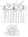
- FIG. 1 is an axial cross-sectional view of the rolling bearing device of the first embodiment.
- 2 and 3 are axial sectional views showing the sealing member according to the first embodiment and its periphery mounted on the rolling bearing device shown in FIG. 2 uses the XX line in FIG. 4 as a cut surface, and FIG. 3 uses the YY line in FIG. 4 as a cut surface.
- FIG. 4 is an end view taken along the line ZZ of the sealing member shown in FIG.
- the rolling bearing device 1 supports, for example, a roll neck (rotating shaft) 2 of a rolling roll so as to be rotatable, and seals the rolling bearing 10 and the inside of the bearing of the rolling bearing 10. Member 20.
- the rolling roll is cooled by spraying cooling water.
- the side (or direction) from the inside to the outside of the rolling bearing 10 is referred to as an axially outer side (or axially outward), and the side from the outside to the inside of the rolling bearing 10 is axially inside. That's it.
- the rolling bearing 10 is composed of, for example, four rows of tapered roller bearings.
- the rolling bearing 10 is arranged in each of four rows of first and second inner rings 11 and 12 arranged in a pair in the axial direction, first to third outer rings 13 to 15 arranged in the axial direction, and four rows.
- a plurality of tapered rollers (rolling elements) 16 and four cages 17 are provided.
- the first and second inner rings 11 and 12 are externally fitted to the roll neck 2 in a state where the end portions 11b and 12b on the inner sides in the axial direction are abutted with each other.
- Two inner ring raceway surfaces 11a and 12a are formed on the outer peripheral surfaces of the inner rings 11 and 12, respectively, in the axial direction.
- Helical lubrication grooves 11c and 12c are formed on the inner peripheral surfaces of the inner rings 11 and 12 to receive grease as a lubricant for preventing seizure of the inner peripheral surfaces.
- An annular groove 18 is formed across the inner rings 11, 12 on the outer periphery of the portion of the inner rings 11, 12 where the end portions 11 b, 12 b are butted together.
- the bottom surface of the annular groove 18 has a first peripheral surface 18a formed on the first inner ring 11 side and a second peripheral surface 18b formed on the second inner ring 12 side (see FIG. 2).
- a plurality of through-holes 33 penetrating the butted portions in the radial direction are provided at a predetermined interval in the circumferential direction at the portions where the end portions 11b and 12b of the inner rings 11 and 12 are butted together. Yes.
- By providing the through hole 33 air is efficiently introduced into the annular space 19 formed between the first and second inner rings 11 and 12 and the first to third outer rings 13 to 15 through the through hole 33. Can be introduced, or the air in the annular space 19 can be discharged.
- the first to third outer rings 13 to 15 are fitted to the inner peripheral surface of a rolling roll housing (not shown) on the outer side in the radial direction of the inner rings 11 and 12.
- One outer ring raceway surface 13 a, 15 a is formed on the inner peripheral surface of the first and third outer rings 13, 15.
- Two outer ring raceway surfaces 14 a are formed on the inner circumference of the second outer ring 14 in the axial direction.
- the tapered rollers 16 are rollable between the inner ring raceways 11a and 12a of the inner rings 11 and 12 and the outer ring raceways 13a to 15a of the outer rings 13 to 15 and are arranged in a double row (here, four rows). ing. Each cage 17 holds a circumferential interval between the tapered rollers 16 in each row.
- the rolling bearing device 1 includes a pair of bearing seals 21 mounted on both ends of the rolling bearing 10 in the axial direction as sealing members 20, and an inner ring seal mounted on the annular groove 18 in the axial center of the rolling bearing 10. 22.
- the inner ring seal 22 is the sealing member of the embodiment of the present invention.
- the bearing seal 21 seals both axial ends of the annular space 19 included in the rolling bearing 10.
- the bearing seal 21 has an annular cover 21a fixed to the axially outer end face of the first outer ring 13 (third outer ring 15), and an annular seal 21b fixed to the inner periphery of the cover 21a.
- the seal 21b is made of an elastic material such as synthetic rubber, and a lip portion 21c that is slidably in contact with the outer peripheral surface on the outer side in the axial direction of the first inner ring 11 (second inner ring 12) is formed on the inner peripheral end thereof.
- the bearing seal 21 functions to prevent cooling water from entering the annular space 19 from the outside in the axial direction of the rolling bearing 10.
- the inner ring seal 22 includes an annular cored bar 23 having a substantially L-shaped cross section, and an annular elastic portion 24 fixed to the cored bar 23.
- the core metal 23 is made of, for example, a metal annular member, and includes a cylindrical portion 23a and an annular plate portion 23b that is bent radially inward from one axial end portion of the cylindrical portion 23a.
- the elastic portion 24 is made of an elastic material such as synthetic rubber, and is fixed to the core metal 23 by vulcanization bonding or baking.
- the elastic portion 24 includes an annular base end portion 25 provided on the first inner ring 11 side and an extending portion 26 extending from the base end portion 25 to the second inner ring 12 side.
- the extending portion 26 extends to the vicinity of the side surface 18c of the annular groove 18 on the second inner ring 12 side.
- a first fixed lip 25a and a second fixed lip 25b adjacent to the first fixed lip 25a in the axial direction are provided on the inner peripheral surface of the base end portion 25.
- the first and second fixed lips 25a and 25b are in contact with the first peripheral surface 18a.
- the first and second fixed lips 25a and 25b are externally fitted to the first peripheral surface 18a with a predetermined tightening allowance, and are not moved relative to the first peripheral surface 18a by the tightening force.
- the inner ring seal 22 is attached to the first inner ring 11 so as to be integrally rotatable.
- a sliding contact lip 26 a is provided on the inner peripheral surface of the extending portion 26.
- the sliding contact lip 26a is in contact with the second peripheral surface 18b.
- the sliding contact lip 26a is in contact with the second peripheral surface 18b with a lower pressing force than the first and second fixed lips 25a, 25b. Therefore, the sliding contact lip 26a is configured to be in sliding contact with the second peripheral surface 18b of the annular groove 18 when the first inner ring 11 and the second inner ring 12 are relatively rotated. That is, the inner ring seal 22 is slidable with respect to the second inner ring 12.
- the annular extending portion 26 has the recessed portion forming regions 31 and the recessed portion non-forming regions 32 arranged alternately along the circumferential direction.
- eight concave portion forming regions 31 and eight concave portion non-forming regions 32 are alternately arranged.
- the recessed portion forming region 31 of the extending portion 26 includes an inner thin portion 27 and an outer thin portion 28 that extend from the base end portion 25 to the second inner ring 12 side.
- the inner thin portion 27 and the outer thin portion 28 are thinner in the radial direction than the base end portion 25.
- the inner thin portion 27 is provided with a sliding contact lip 26a on the inner peripheral surface.
- the outer thin portion 28 is located radially outward of the inner thin portion 27 and spaced from the inner thin portion 27.
- the recess 29 is provided in the recess formation region 31, the inner thin portion 27, the base end portion 25, the outer thin portion 28, and the thick portion 30 of the recess non-formation region 32 (FIG. 3, 4).
- the recess 29 is an indent having an opening 29a on the second inner ring 12 side of the extending portion 26 and having the axial direction as the depth direction.
- the bottom 29 b of the recess 29 is located closer to the first inner ring 11 than the abutting surface between the end 11 b of the first inner ring 11 and the end 12 b of the second inner ring 12.
- the shape of the opening 29 a of the recess 29 is an arc shape curved along the circumferential direction.
- the number of the recessed portion forming regions 31 and the recessed portion non-forming regions 32 is not limited to 8 each, and may be 7 or less, or may be 9 or more. Is possible.
- the recessed portion forming region 31 includes the recessed portion 29, the inner thin portion 27 positioned radially inward of the recessed portion 29 can be easily bent radially outward. Therefore, when the pressure in the annular space 19 of the rolling bearing 10 becomes negative, the sliding contact lip 26a provided on the inner periphery of the inner thin portion 27 is separated from the second peripheral surface 18b of the annular groove 18 radially outward. The negative pressure in the annular space 19 can be eliminated.
- the boundary between the inner thin portion 27 and the base end portion 25 is closer to the first inner ring 11 side than the abutting surface between the end portion 11 b of the first inner ring 11 and the end portion 12 b of the second inner ring 12. positioned.
- the length (A in FIG. 2) of the inner thin portion 27 in the axial direction is longer than that in the case where the boundary portion is located on the second inner ring 12 side with respect to the abutting surface.
- the inner thin portion 27 having such a long axial length is bent in a direction (radially outward) in which the sliding contact lip 26a is separated from the second peripheral surface when the inside of the rolling bearing 10 is under negative pressure.
- the inner ring seal 22 including the inner thin portion 27 is suitable for eliminating the negative pressure in the annular space 19.
- the recessed portion non-forming region 32 of the extending portion 26 has a thick portion 30 that extends from the base end portion 25 to the second inner ring 12 side.
- the thick portion 30 has a radial thickness comparable to that of the base end portion 25.
- the thick portion 30 is provided with a sliding contact lip 26a on the inner peripheral surface. That is, the recess non-forming region 32 has a shape in which the recess 29 in the recess forming region 31 is closed, and is configured in the same manner as the recess forming region 31 except that the entire portion is composed of the thick portion 30.
- the concave portion non-forming region 32 is less likely to bend than the concave portion forming region 31, and the sliding contact lip 26a provided on the inner peripheral surface of the thick portion 30 is difficult to separate from the second peripheral surface 18b.
- the distal end portion 30a on the other end side in the axial direction (the right side in FIGS. 2 to 3) of the thick portion 30 in this embodiment is more relevant than the distal end portion 27a on the other end side in the axial direction of the inner thin portion 27. It protrudes to the other end side in the axial direction.
- the inner ring seal 22 is formed in the annular space 19 of the rolling bearing 10 due to the presence of the recess forming region 31 having the inner thin portion 27 that can be easily bent radially outward by the negative pressure generated in the rolling bearing 10.
- the presence of the recess non-formation region 32 that is harder to bend than the recess formation region 31 causes the inner ring seal 22 to be deformed when mounted on the rolling bearing 10, and It can be avoided that the portion remains turned up or is sandwiched between the end portions 11b, 12b of the first and second inner rings 11, 12.
- the thick portion 30 that is not easily deformed comes into contact with the end portion 12b of the second inner ring 12, so that the deformation of the inner thin portion 27 and the ends of the first and second inner rings 11, 12 are performed.
- the sandwiching between the portions 11b and 12b can be prevented.
- the inner ring seal 22 is to be attached to the inner ring in a state where the center of the inner ring seal 22 is eccentric from the center of the inner ring, the inner ring follows the inner wall ring seal 22 following the thick portion 30 that first contacts the inner ring. Therefore, the burden on the inner thin portion 27 can be reduced when the inner ring seal 22 is attached to the inner ring.
- the inner ring seal 22 is usually mounted on the rolling bearing 10 after the inner ring seal 22 is externally fitted to the second peripheral surface 18 b provided on the second inner ring 12, and then the end 11 b of the first inner ring 11. This is done by fitting the first peripheral surface 18a provided on the first inner ring 11 into the inner ring seal 22 so that the end 12b of the second inner ring 12 abuts.
- the sum of the circumferential lengths C of the inner thin portions 27 of the respective recess formation regions 31 is longer than the sum of the circumferential lengths D of the thick portions 30 of the respective recess non-formation regions 32. .
- the rolling bearing device 1 when the inside of the annular space 19 becomes negative pressure, the sliding contact lip 26 a is easily separated from the second peripheral surface 18 b of the annular groove 18, and the negative pressure in the annular space 19 is eliminated. More suitable to do.
- the axial center of the extending portion 26 P in FIG. 4
- the circumferential lengths of the regions on the same radius are measured and compared.
- FIG. 5 is an end view of the sealing member of the second embodiment.
- the inner ring seal 42 according to the present embodiment includes a core metal 43 and an annular elastic portion 44 made of an elastic material fixed to the core metal 43.
- the configuration of the cored bar 43 is the same as that of the cored bar 23 of the first embodiment.
- the elastic portion 44 includes an annular base end portion and an annular extension portion 46 extending from the base end portion.
- the extension portion 46 extends along the circumferential direction from the recess forming region 51 and the recess non-extension portion.
- the formation regions 52 are alternately arranged.
- the configuration of the elastic portion 44 is different from the extending portion 26 of the first embodiment in the number of the recessed portion forming regions 51 and the recessed portion non-forming regions 52 in the extending portion 46 and the respective lengths in the circumferential direction. This is the same as the elastic part 24 of the first embodiment.
- the extending portion 46 includes a concave portion forming region 51 having an inner thin portion 47, an outer thin portion 48, and a concave portion 49 sandwiched therebetween, and a concave portion not entirely formed by a thick portion 50.
- Four regions 52 are alternately arranged.
- Such an inner ring seal 42 can also eliminate the negative pressure in the annular space 19 of the rolling bearing 10 due to the presence of the recessed portion forming region 51, and the presence of the recessed portion non-formed region 52 can prevent the negative pressure in the annular bearing 19. Excellent mountability when mounting.
- the degree of protrusion of the thick portion 30 toward the other end side in the axial direction is adjusted so that the axial width L2 of the inner ring seal 22 is equal to or less than the width L1 of the annular groove 18.
- the width L2 is larger than the width L1
- a gap is generated at the abutting surface between the first inner ring 11 and the second inner ring 12 in which the inner ring seal 22 is mounted in the annular groove 18, and foreign matter enters the bearing from the gap.
- the width L2 is preferably equal to or less than the width L1.
- the sum of the circumferential lengths E of the inner thin portions 47 of the respective recess forming regions 51 is shorter than the sum of the circumferential lengths F of the thick portions 50 of the respective recess non-forming regions 52. . Therefore, when the inner ring seal 42 is mounted on the rolling bearing 10, the inner ring seal 42 is more difficult to deform than the inner ring seal 22, and the inner ring seal 42 is more easily assembled. Further, in the present embodiment, the distal end portion 30a of the thick wall portion 30 protrudes, and this protruding portion can serve as a stopper when the inner ring seal 22 is assembled to the inner ring. It can be done easily.
- the inner ring seal 22 moves to the other end side in the axial direction (the right side in FIG. 2), and the front end surface 30a1 of the front end portion 30a of the thick portion 30 is the side surface 18c on the other end side in the axial direction of the annular groove 18. Even if it contacts, air passage between the outside of the bearing and the inside of the bearing is secured by the presence of the recess forming region 31 (see FIG. 2).
- FIG. 6 is a cross-sectional view of another embodiment of the sealing member of the present invention, showing a cross section corresponding to the cross section shown in FIG. 2 in the embodiment shown in FIGS.
- the same components as those in the embodiment shown in FIGS. 1 to 4 are denoted by the same reference numerals, and description thereof will be omitted for simplicity.
- the distal end portion 40 a of the thick portion 40 is a second peripheral surface that forms the bottom surface of the annular groove 18 toward the other end side in the axial direction at the radially inner portion of the distal end portion 40 a. It has the 1st inclined surface 41 which leaves
- the distal end portion 37a of the inner thin portion 37 is a second inner surface that is separated from the second peripheral surface 18b that forms the bottom surface of the annular groove 18 toward the other end side in the axial direction at the radially inner portion of the distal end portion 37a.
- An inclined surface 42 is provided.
- the angle ⁇ formed by the first inclined surface 41 with the second peripheral surface 18b of the annular groove 18 is smaller than the angle ⁇ formed by the second inclined surface 42 with the second peripheral surface 18b of the annular groove 18, and is shown in FIG.
- the angle ⁇ is set to approximately half of the angle ⁇ .
- the angle ⁇ formed by the first inclined surface 41 of the distal end portion 40a of the thick portion 40 and the second peripheral surface 18b of the annular groove 18 is such that the second inclined surface 42 of the distal end portion 37a of the inner thin portion 37 is annular. If the angle ⁇ formed with the second peripheral surface 18b of the groove 18 is smaller, the second inclined surface 42 of the distal end portion 37a of the inner thin portion 37 when the inter-inner ring seal 22 is attached to the end of the inner ring of the rolling bearing.
- the first inclined surface 41 of the distal end portion 40a of the thick wall portion 40 comes into contact with the end portion of the inner ring before coming into contact with the end portion of the inner ring, and a guide when the inner ring seal 22 is attached to the end portion of the inner ring. Play a role. Therefore, the inner ring seal 22 can be more smoothly attached to the end of the inner ring of the rolling bearing.
- the first inclined surface 41 of the distal end portion 40a of the thick wall portion 40 also serves to center the inner ring when the inner ring seal 22 is mounted on the end of the inner ring of the rolling bearing. That is, even if the inner ring seal 22 is to be attached to the end of the inner ring in a state where the center of the inner ring is eccentric with respect to the center of the inner ring seal 22, the inner ring contacts the first inclined surface 41, and the first inclined surface By moving along 41, the centers of the inner ring seal 22 and the inner ring coincide with each other.
- the present invention is not limited to the above embodiment and can be implemented with appropriate modifications.
- the sealing member (sealing between inner rings) of the first and second embodiments the recessed portion forming region and the recessed portion non-forming region are arranged at equal intervals along the circumferential direction, but the sealing member of the embodiment of the present invention Then, each of the recess formation region and the recess non-formation region does not necessarily have to be arranged at equal intervals. Further, the circumferential lengths of the respective recessed portion forming regions are not necessarily the same, and the circumferential length may be different for each recessed portion forming region.
- the circumferential lengths of the non-recessed regions need not all be the same, and the circumferential length may be different for each non-recessed region. Furthermore, the number of each of the recessed portion forming region and the recessed portion non-forming region is not limited, and at least one each may be provided. The arrangement, circumferential length, number, etc., of these recessed portion forming regions and recessed portion non-forming regions are all appropriately selected in consideration of ease of eliminating negative pressure inside the rolling bearing, ease of incorporation into the rolling bearing, and the like. It ’s fine.
- the number of the fixed lips is: There may be one or three or more.
- the angle ⁇ formed by the first inclined surface of the distal end portion of the thick portion with the second peripheral surface of the annular groove is set, and the second inclined surface of the distal end portion of the inner thin portion is the second angle of the annular groove.
- the rolling bearing used in the embodiment of the present invention is not limited to the rolling bearing used for supporting the roll neck of the rolling roll, and may be a rolling bearing used for other devices (uses).
Abstract
Description
転がり軸受100は、ロールネック4に外嵌される一対の第1及び第2内輪101,102と、ハウジングに固定される複数の第1~第3外輪103~105と、上記各内輪101,102と各外輪103~105との間の環状空間108に配置される複数の円錐ころ106とを備えている。第1及び第2内輪101,102は、第1内輪101の軸方向一方の端部と、第2内輪102の軸方向他方の端部とを、軸方向に突き合わせて配置されている。そして、第1及び第2内輪101,102における上記端部同士を突き合わせた部分の外周には環状溝107が設けられている。この環状溝107は、第1及び第2内輪101,102の端部に段差を設けることにより構成されている。
内輪間シール220は、環状の芯金部221と、この芯金部221に固定された弾性部222とからなる。この弾性部222は、環状溝107における第1内輪101側の周面に外嵌する一対の固定リップ223aを内周面に備えた基端部223と、環状溝107における第2内輪102側の周面に接触する摺接リップ224aを内周面に備えた延設部224とを有している。摺接リップ224aは、第1内輪101と第2内輪102とが相対的に回転したときに、環状溝107における第2内輪102側の周面と摺動するようになっている。
内輪間シール220は、ロールネック4の外周面から第1及び第2内輪101,102の突き合わせた端部同士の間を通過して環状溝107に浸入した冷却水や圧延油が環状空間108に浸入したり、環状空間108内のグリースが外部に漏れだしたりすることを防止している。
これに対して、内輪間シールとして、図7に示したような、周方向全体に内輪102の外周面に接触する摺接リップ224aを備えた延設部224を有する内輪間シール220を用いた場合、転がり軸受100の内部の圧力が低下して環状空間108が負圧となった際に、内輪102の外周面に設けられた環状溝107の底部から摺接リップ224aが径方向外方に離反し、環状空間108の負圧を解消させることができる。
すなわち、第2内輪102の端部の段差部分に内輪間シール220の延設部224を外嵌した後、第1内輪101の端面と第2内輪102の端面とが突き合うように第1内輪101の端部の段差部分を内輪間シール220の基端部223に内嵌することによって、内輪間シール220を環状溝107に装着する。
このようにして内輪間シール220を転がり軸受100に装着する場合、内輪間シール220の延設部224を第2内輪102の端部の段差部分に外嵌した際に、延設部224の一部がめくれたままになる。また、組付け時に誤って、内輪間シール220の基端部223を第1内輪101の端部の段差部分に外嵌した後、第1内輪101の端面と第2内輪102の端面とが突き合うように第2内輪102の端部の段差部分を内輪間シール220の延設部224に内嵌すると、延設部224の一部が変形して第1内輪101と第2内輪102との間に挟み込まれる。このため、周方向全体に薄肉の延設部224を有する内輪間シール220は転がり軸受100への組込み性に劣る。
密封部材は、弾性素材からなる環状の弾性部を有する。
密封部材は、環状溝に装着される。
弾性部は、環状溝の軸方向の一端側に固定される環状の基端部と、基端部から軸方向の他端側に延びて、内周に上記環状溝の軸方向の他端側と摺接する摺接リップを有する環状の延設部と、を有する。
延設部は、周方向に沿って基端部よりも径方向の肉厚が薄く、転がり軸受の内部に生じる負圧によって径方向外方に撓んで上記摺接リップが環状溝から離反し得る薄肉部と、この薄肉部よりも径方向の肉厚が厚い厚肉部とを有する。薄肉部と厚肉部とは交互に配置され、
前記厚肉部の前記軸方向の他端側の先端部は、前記薄肉部の前記軸方向の他端側の先端部よりも当該軸方向の他端側に突出している。
また、延設部は、薄肉部と周方向に沿って交互に配置された、薄肉部よりも径方向の肉厚が厚く前記薄肉部よりも変形しにくい厚肉部も有している。そのため、密封部材は、転がり軸受に装着する際に変形しにくく、装着時に延設部の一部がめくれたままになってしまったり、延設部の一部が変形して互いに突き合わせる一対の内輪の端部同士の間に挟まったりすることがなく、組込み性に優れる。また、厚肉部の軸方向の他端側の先端部は、前記薄肉部の軸方向の他端側の先端部よりも当該軸方向の他端側に突出しており、密封部材を転がり軸受の内輪の端部に装着するに際しては、当該厚肉部の軸方向の他端側の先端部が当該内輪の端部と接触する。
従って、密封部材は、転がり軸受内部が負圧になった際に、負圧を解消することができ、かつ、装着時の組込み性に優れる。
この場合、薄肉部は、転がり軸受の内部が負圧となった際に、径方向外方に撓みやすく、摺接リップが環状溝からより離反しやすくなる。
この場合、延設部において撓みやすい薄肉部の占める割合が多くなるため、転がり軸受内部が負圧となった際に、摺接リップが環状溝から離反しやすく、より効果的に転がり軸受内部の負圧を解消することができる。
延設部において、薄肉部より変形しにくい厚肉部の占める割合が多いため、密封部材の装着時における組込み性をより向上させることができる。
前記薄肉部の先端部は、当該先端部の径方向内側部分に、前記軸方向の他端側に向かうにつれて前記環状溝の底面から離反する第2傾斜面を有し、
前記第1傾斜面が前記環状溝の底面となす角度は、前記第2傾斜面が前記環状溝の底面となす角度以下としてもよい。この場合、厚肉部の先端部の第1傾斜面が前記環状溝の底面となす角度が、薄肉部の先端部の第2傾斜面が前記環状溝の底面となす角度以下であるので、密封部材を転がり軸受の内輪の端部に装着するに際しては、薄肉部の先端部の第2傾斜面が内輪の端部と接触する前に厚肉部の先端部の第1傾斜面が当該内輪の端部と接触して、密封部材を内輪の端部に装着するときのガイドの役割を果たす。したがって、密封部材をよりスムーズに転がり軸受の内輪の端部に装着することができる。
薄肉部の軸方向の長さを長くすることができるため、薄肉部の形状を径方向外方により撓みやすく、転がり軸受内部の負圧を解消するのに特に適した形状とすることができる。
また、転がり軸受装置では、組立時に、延設部の一部がめくれたままになってしまったり、第1内輪及び第2内輪の端部同士を突きあわせる部分に挟み込まれたりすることがない。
[第1実施形態]
図1は、第1実施形態の転がり軸受装置の軸方向断面図である。図2、3は、いずれも図1に示した転がり軸受装置に装着された第1実施形態の密封部材とその周辺を示す軸方向断面図である。なお、図2は、図4におけるX-X線を切断面とし、図3は、図4におけるY-Y線を切断面とする。図4は、図2に示した密封部材のZ-Z線端面図である。
図1に示すように、転がり軸受装置1は、例えば圧延ロールのロールネック(回転軸)2を回転自在に支持するものであり、転がり軸受10と、この転がり軸受10の軸受内部を密封する密封部材20とを備えている。なお、圧延ロールは冷却水を噴射することによって冷却される。
以下、本明細書においては、転がり軸受10の内部から外部へ向かう側(又は方向)を軸方向外側(又は軸方向外方)といい、転がり軸受10の外部から内部へ向かう側を軸方向内側という。
転がり軸受10は、例えば4列の円錐ころ軸受からなる。転がり軸受10は、軸方向に一対配置された第1及び第2内輪11,12と、軸方向に3つ配置された第1~第3外輪13~15と、4列のそれぞれに配置された複数の円錐ころ(転動体)16と、4つの保持器17とを備えている。
両内輪11,12における端部11b,12b同士を突き合わせた部分には、突き合わせた部分を径方向に貫通する貫通孔33(図2参照)が、周方向に所定間隔をおいて複数設けられている。貫通孔33を設けることにより、貫通孔33を介して、第1及び第2内輪11,12と、第1~第3外輪13~15との間に形成される環状空間19内に効率よく空気を導入したり、環状空間19内の空気を排出したりすることができる。
各保持器17は、各列の円錐ころ16の周方向の間隔をそれぞれ保持している。
転がり軸受装置1は、密封部材20として、転がり軸受10の軸方向両端部にそれぞれ装着された一対の軸受シール21と、転がり軸受10の軸方向中央部の環状溝18に装着された内輪間シール22とを備えている。ここで、内輪間シール22が本発明の実施形態の密封部材である。
軸受シール21は、第1外輪13(第3外輪15)の軸方向外側の端面に固定された環状のカバー21aと、このカバー21aの内周に固定された環状のシール21bとを有する。シール21bは、合成ゴムなどの弾性素材からなり、その内周端部には第1内輪11(第2内輪12)の軸方向外側の外周面に摺接するリップ部21cが形成されている。これにより、軸受シール21は、転がり軸受10の軸方向外方から環状空間19に冷却水が浸入するのを防ぐ働きをする。
芯金23は、例えば金属製の環状部材からなり、円筒部23aと、円筒部23aの軸方向一端部から径方向内方に折り曲げられた環状板部23bとを有する。
弾性部24は、合成ゴムなどの弾性素材からなり、芯金23に加硫接着、焼き付けなどで固定されている。弾性部24は、芯金23の円筒部23aの外周面23a1よりも径方向内方に位置している。
なお、図2は図4におけるX-X線を切断面とする断面図であり、図3は図4におけるY-Y線を切断面とする断面図である。
基端部25の内周面には、第1固定リップ25aと、第1固定リップ25aに軸方向に隣接する第2固定リップ25bとが設けられている。第1及び第2固定リップ25a,25bは、第1周面18aに接触している。
第1及び第2固定リップ25a,25bは、所定の締め代をもって第1周面18aに外嵌されており、その緊迫力により第1周面18aに対して相対移動しないようになっている。これにより、内輪間シール22は、第1内輪11に一体回転可能に装着されている。
摺接リップ26aは、第1及び第2固定リップ25a,25bより低い緊迫力で第2周面18bに接触している。そのため、摺接リップ26aは、第1内輪11と第2内輪12とが相対的に回転した場合、環状溝18の第2周面18bに対して摺接するようになっている。つまり、内輪間シール22は、第2内輪12に対して摺動可能である。
また、延設部26の外端面の外周側には、環状溝18の第2内輪12側の側面18cに対して摺接可能に面接触する突起部26bが周方向に所定間隔をおいて複数突設されている。
凹部29の開口部29aの形状は、図4に示すように、周方向に沿って湾曲した円弧形状である。なお、この凹部形成領域31と凹部非形成領域32の数は、各8つに限定されるものではなく、各7つ以下とすることも可能であり、また、各9つ以上とすることも可能である。
すなわち、凹部非形成領域32は、凹部形成領域31における凹部29が閉塞された形状を有し、全体が厚肉部30からなる以外は、凹部形成領域31と同様に構成されている。
そのため、凹部非形成領域32は凹部形成領域31に比べて撓みにくく、厚肉部30の内周面に設けられた摺接リップ26aは、第2周面18bから離反しにくくなっている。
また、本実施形態における厚肉部30の軸方向の他端側(図2~3において右側)の先端部30aは、前記内側薄肉部27の軸方向の他端側の先端部27aよりも当該軸方向の他端側に突出している。このため、密封部材である内輪間シール22を転がり軸受10の内輪の端部に装着するに際しては、当該厚肉部30の軸方向の他端側の先端部30aが当該内輪の端部と接触する。
さらに、転がり軸受10への装着時には、変形しにくい厚肉部30が第2内輪12の端部12bと接触するので、内側薄肉部27の変形や、第1及び第2内輪11,12の端部11b,12b同士の間への挟み込みを防止することができる。また、内輪間シール22の中心が内輪の中心と偏心した状態で当該内輪間シール22を内輪に装着しようとしても、内輪と最初に接触する厚肉部30に倣って当該内輪が内輪間シール22の中心側に移動するので、内輪間シール22の内輪への装着に際し、内側薄肉部27への負担を緩和させることができる。
なお、内輪間シール22の転がり軸受10への装着は、通常、第2内輪12に設けられた第2周面18bに内輪間シール22を外嵌した後、第1内輪11の端部11bと第2内輪12の端部12bとが突き合うように第1内輪11に設けられた第1周面18aを内輪間シール22に内嵌することにより行う。
なお、各内側薄肉部27の周方向長さCの和と、各厚肉部30の周方向長さDの和とを比較する場合、延設部26の軸中心(図4中、P)から同一半径上にある各領域の周方向長さを測定して比較する。
本実施形態では、内輪間シール42が第1実施形態とは異なる。
図5は、第2実施形態の密封部材の端面図である。
本実施形態の内輪間シール42は、芯金43と、芯金43に固定された弾性素材からなる環状の弾性部44とを有する。芯金43の構成は第1実施形態の芯金23と同様である。
弾性部44は、環状の基端部とこの基端部から延在する環状の延設部46とを備えており、延設部46は、周方向に沿って、凹部形成領域51と凹部非形成領域52とが交互に配置されている。弾性部44の構成は、延設部46における凹部形成領域51及び凹部非形成領域52の個数とそれぞれの周方向の長さとが第1実施形態の延設部26とは異なり、その他に構成は、第1実施形態の弾性部24と同様である。
このような内輪間シール42もまた、凹部形成領域51の存在により、転がり軸受10の環状空間19内の負圧を解消することができ、凹部非形成領域52の存在により、転がり軸受10への装着する際の組込み性に優れる。
また、内輪間シール22の軸方向の幅L2が環状溝18の幅L1以下になるように前記厚肉部30の軸方向の他端側への突出の程度を調整している。幅L2が幅L1よりも大きい場合、内輪間シール22を環状溝18内に装着した第1内輪11と第2内輪12との突合せ面に隙間が生じ、当該隙間から軸受内部に異物が侵入する恐れがある。したがって、このような異物の侵入を避けるためには、幅L2は幅L1以下であることが好ましい。
また、本実施形態では、厚肉部30の先端部30aが突出しており、この突出した部分は、内輪間シール22を内輪に組み付けるときのストッパーとしての役割を果たすことができるので、組み付け作業を容易に行うことができる。
なお、内輪間シール22が軸方向の他端側(図2において右側)に移動して、厚肉部30の先端部30aの先端面30a1が環状溝18の軸方向の他端側の側面18cと当接したとしても、凹部形成領域31の存在により、軸受外部と軸受内部との空気の通路は確保されている(図2参照)。
図6に示される実施形態における厚肉部40の先端部40aは、当該先端部40aの径方向内側部分に、軸方向の他端側に向かうにつれて環状溝18の底面を構成する第2周面18bから離反する第1傾斜面41を有している。また、内側薄肉部37の先端部37aは、当該先端部37aの径方向内側部分に、軸方向の他端側に向かうにつれて環状溝18の底面を構成する第2周面18bから離反する第2傾斜面42を有している。第1傾斜面41が前記環状溝18の第2周面18bとなす角度αは、第2傾斜面42が前記環状溝18の第2周面18bとなす角度βよりも小さく、図6に示される実施形態では、角度αは角度βのほぼ半分に設定されている。このように、厚肉部40の先端部40aの第1傾斜面41が環状溝18の第2周面18bとなす角度αが、内側薄肉部37の先端部37aの第2傾斜面42が環状溝18の第2周面18bとなす角度βよりも小さいと、内輪間シール22を転がり軸受の内輪の端部に装着するときに、内側薄肉部37の先端部37aの第2傾斜面42が内輪の端部と接触する前に厚肉部40の先端部40aの第1傾斜面41が当該内輪の端部と接触して、内輪間シール22を内輪の端部に装着するときのガイドの役割を果たす。したがって、内輪間シール22をよりスムーズに転がり軸受の内輪の端部に装着することができる。
本発明は、前記実施形態に限定されることなく適宜変更して実施可能である。
第1及び第2実施形態の密封部材(内輪間シール)では、凹部形成領域及び凹部非形成領域のそれぞれが周方向に沿って等間隔で配置されているが、本発明の実施形態の密封部材では、凹部形成領域及び凹部非形成領域のそれぞれは、必ずしも等間隔で配置されていなくても良い。
また、各凹部形成領域の周方向長さはすべて同一である必要はなく、凹部形成領域ごとに周方向長さが異なっていても良い。各凹部非形成領域の周方向長さもまた、すべて同一である必要はなく、凹部非形成領域ごとに周方向長さが異なっていても良い。
更に、凹部形成領域及び凹部非形成領域のそれぞれの個数も限定されず、それぞれ少なくとも1つずつあれば良い。
これらの凹部形成領域及び凹部非形成領域の配置、周方向長さ、個数等は、いずれも転がり軸受内部の負圧の解消しやすさ、転がり軸受への組込み性などを考慮して適宜選択すれば良い。
なお、前述した実施形態では、厚肉部の先端部の第1傾斜面が環状溝の第2周面となす角度αを、内側薄肉部の先端部の第2傾斜面が環状溝の第2周面bとなす角度βよりも小さくしているが、角度α=角度βの場合でも、前記とほぼ同等の効果を奏することができる。
Claims (8)
- 転がり軸受用の密封部材であって、前記転がり軸受は、軸方向の端部同士を突き合わせた状態で回転軸に外嵌される一対の内輪、前記一対の内輪の径方向外方に配置される外輪、前記一対の内輪の端部同士の突き合わせ部分の外周に設けられた環状溝を有し、
前記転がり軸受用の密封部材は、弾性素材からなる環状の弾性部を具備し、
前記転がり軸受用の密封部材は、前記環状溝に装着され、
前記弾性部は、前記環状溝の軸方向の一端側に固定される環状の基端部と、前記基端部から軸方向の他端側に延びて、内周に前記環状溝の軸方向の他端側と摺接する摺接リップを有する環状の延設部と、を有し、
前記延設部は、周方向に沿って前記基端部よりも径方向の肉厚が薄く、転がり軸受の内部に生じる負圧によって径方向外方に撓んで前記摺接リップが前記環状溝から離反し得る薄肉部と、この薄肉部よりも径方向の肉厚が厚い厚肉部とを有し、
前記薄肉部と前記厚肉部とが交互に配置される、
転がり軸受用の密封部材。 - 前記延設部は、前記軸方向の他端側で開口し軸方向を深さ方向とする凹部を有し、
前記凹部の径方向内方に前記薄肉部が設けられている、
請求項1に記載の転がり軸受用の密封部材。 - 前記延設部において、前記薄肉部の周方向長さの和は、前記厚肉部の周方向長さの和よりも長い、
請求項1又は2に記載の転がり軸受用の密封部材。 - 前記延設部において、前記薄肉部の周方向長さの和は、前記厚肉部の周方向長さの和よりも短い、
請求項1又は2に記載の転がり軸受用の密封部材。 - 前記薄肉部と前記基端部との境界部は、前記一対の内輪の端部同士の突き合わせ面よりも前記軸方向の一端側に位置する、
請求項1~4のいずれかに記載の転がり軸受用の密封部材。 - 前記厚肉部の前記軸方向の他端側の先端部は、前記薄肉部の前記軸方向の他端側の先端部よりも当該軸方向の他端側に突出している、
請求項1~5のいずれかに記載の転がり軸受用の密封部材。 - 前記厚肉部の先端部は、当該先端部の径方向内側部分に、前記軸方向の他端側に向かうにつれて前記環状溝の底面から離反する第1傾斜面を有し、
前記薄肉部の先端部は、当該先端部の径方向内側部分に、前記軸方向の他端側に向かうにつれて前記環状溝の底面から離反する第2傾斜面を有し、
前記第1傾斜面が前記環状溝の底面となす角度は、前記第2傾斜面が前記環状溝の底面となす角度以下である、
請求項6に記載の転がり軸受用の密封部材。 - 転がり軸受装置であって、
前記一対の内輪と、前記外輪と、前記環状溝と、前記外輪と前記内輪との間に配置された転動体と、を有する転がり軸受と、請求項1~7のいずれかに記載の転がり軸受用の密封部材と、
を具備し、
前記一対の内輪は、前記内輪の軸方向に端部同士が突き合わされた第1内輪と第2内輪とを有し、
前記環状溝は、前記第1内輪と前記第2内輪とが突き合わされた部分の外周面に設けられ、
前記環状溝に前記転がり軸受用の密封部材が装着されている、
転がり軸受装置。
Priority Applications (4)
| Application Number | Priority Date | Filing Date | Title |
|---|---|---|---|
| CN201780009563.9A CN108603532B (zh) | 2016-02-02 | 2017-02-02 | 滚动轴承用的密封构件及滚动轴承装置 |
| DE112017000612.0T DE112017000612T5 (de) | 2016-02-02 | 2017-02-02 | Dichtungsbauteil für ein Wälzlager und für eine Wälzlagerbaugruppe |
| US16/075,022 US10550891B2 (en) | 2016-02-02 | 2017-02-02 | Seal member for rolling bearing and rolling bearing assembly |
| KR1020187022310A KR20180105663A (ko) | 2016-02-02 | 2017-02-02 | 구름 베어링용 밀봉 부재 및 구름 베어링 장치 |
Applications Claiming Priority (4)
| Application Number | Priority Date | Filing Date | Title |
|---|---|---|---|
| JP2016-017777 | 2016-02-02 | ||
| JP2016017777A JP6583026B2 (ja) | 2016-02-02 | 2016-02-02 | 転がり軸受用の密封部材、及び、転がり軸受装置 |
| JP2016-092398 | 2016-05-02 | ||
| JP2016092398A JP6658278B2 (ja) | 2016-05-02 | 2016-05-02 | 転がり軸受用の密封部材、及び、転がり軸受装置 |
Publications (1)
| Publication Number | Publication Date |
|---|---|
| WO2017135352A1 true WO2017135352A1 (ja) | 2017-08-10 |
Family
ID=59499622
Family Applications (1)
| Application Number | Title | Priority Date | Filing Date |
|---|---|---|---|
| PCT/JP2017/003720 WO2017135352A1 (ja) | 2016-02-02 | 2017-02-02 | 転がり軸受用の密封部材、及び、転がり軸受装置 |
Country Status (5)
| Country | Link |
|---|---|
| US (1) | US10550891B2 (ja) |
| KR (1) | KR20180105663A (ja) |
| CN (1) | CN108603532B (ja) |
| DE (1) | DE112017000612T5 (ja) |
| WO (1) | WO2017135352A1 (ja) |
Families Citing this family (3)
| Publication number | Priority date | Publication date | Assignee | Title |
|---|---|---|---|---|
| DE102019200146A1 (de) * | 2019-01-08 | 2020-07-09 | Aktiebolaget Skf | Wälzlagereinheit und Montageverfahren |
| DE102019130275A1 (de) * | 2019-11-11 | 2021-05-12 | Schaeffler Technologies AG & Co. KG | Radlagereinheit |
| IT202000015169A1 (it) * | 2020-06-25 | 2021-12-25 | Skf Ab | Metodo per l’analisi termica di una unità cuscinetto |
Citations (3)
| Publication number | Priority date | Publication date | Assignee | Title |
|---|---|---|---|---|
| JP2000104747A (ja) * | 1998-07-29 | 2000-04-11 | Nsk Ltd | 密封転がり軸受 |
| JP2007092790A (ja) * | 2005-09-27 | 2007-04-12 | Ntn Corp | 密封型転がり軸受 |
| JP2008106824A (ja) * | 2006-10-24 | 2008-05-08 | Jtekt Corp | 密封装置および転がり軸受装置 |
Family Cites Families (10)
| Publication number | Priority date | Publication date | Assignee | Title |
|---|---|---|---|---|
| US4692040A (en) * | 1985-05-06 | 1987-09-08 | The Torrington Company | Multirow roller bearing with seals between the races |
| US5118206A (en) * | 1991-04-15 | 1992-06-02 | Otto Dennis L | Cone bore seal |
| US5213342A (en) * | 1992-02-18 | 1993-05-25 | Federal-Mogul Corporation | Lip seal with radially compressible support band |
| DE4206764A1 (de) * | 1992-03-04 | 1993-09-23 | Skf Gmbh | Abgedichtetes vierreihiges kegelrollenlager, insbesondere fuer arbeitswalzen von walzgeruesten |
| JP3682594B2 (ja) * | 1998-03-11 | 2005-08-10 | 光洋精工株式会社 | ロ−ルネック用軸受の密封装置とこれを用いた圧延機用ロール |
| JP2001032846A (ja) * | 1999-07-16 | 2001-02-06 | Nsk Ltd | 密封転がり軸受 |
| JP3628253B2 (ja) * | 2000-12-14 | 2005-03-09 | 光洋精工株式会社 | 圧延機のロールネック用軸受の密封装置 |
| JP6036215B2 (ja) | 2011-11-29 | 2016-11-30 | 日本精工株式会社 | 組み合わせシールリング付転がり軸受ユニット |
| CN203717637U (zh) * | 2014-02-13 | 2014-07-16 | 日本精工株式会社 | 车轮支承用滚动轴承单元 |
| JP2016017578A (ja) * | 2014-07-08 | 2016-02-01 | 株式会社ジェイテクト | シール及びカバー |
-
2017
- 2017-02-02 WO PCT/JP2017/003720 patent/WO2017135352A1/ja active Application Filing
- 2017-02-02 KR KR1020187022310A patent/KR20180105663A/ko not_active Application Discontinuation
- 2017-02-02 US US16/075,022 patent/US10550891B2/en active Active
- 2017-02-02 CN CN201780009563.9A patent/CN108603532B/zh active Active
- 2017-02-02 DE DE112017000612.0T patent/DE112017000612T5/de active Pending
Patent Citations (3)
| Publication number | Priority date | Publication date | Assignee | Title |
|---|---|---|---|---|
| JP2000104747A (ja) * | 1998-07-29 | 2000-04-11 | Nsk Ltd | 密封転がり軸受 |
| JP2007092790A (ja) * | 2005-09-27 | 2007-04-12 | Ntn Corp | 密封型転がり軸受 |
| JP2008106824A (ja) * | 2006-10-24 | 2008-05-08 | Jtekt Corp | 密封装置および転がり軸受装置 |
Also Published As
| Publication number | Publication date |
|---|---|
| US10550891B2 (en) | 2020-02-04 |
| CN108603532B (zh) | 2020-07-31 |
| US20190055989A1 (en) | 2019-02-21 |
| DE112017000612T5 (de) | 2018-10-18 |
| CN108603532A (zh) | 2018-09-28 |
| KR20180105663A (ko) | 2018-09-28 |
Similar Documents
| Publication | Publication Date | Title |
|---|---|---|
| JP5765424B2 (ja) | シールリング付き転がり軸受 | |
| WO2017135352A1 (ja) | 転がり軸受用の密封部材、及び、転がり軸受装置 | |
| US9958009B2 (en) | Roller bearing | |
| US8226298B2 (en) | Sealing device and rolling bearing apparatus | |
| JP2010190241A (ja) | 自動調心ころ軸受 | |
| KR20180041127A (ko) | 앵귤러 콘택트 볼 베어링 | |
| US10465745B2 (en) | Thrust roller bearing cage and thrust roller bearing | |
| US9638254B2 (en) | Rolling bearing | |
| JP6532651B2 (ja) | シールリング付転がり軸受 | |
| JP6874455B2 (ja) | 転がり軸受 | |
| US20180135693A1 (en) | Tapered roller bearing | |
| JP2015102156A (ja) | 分割保持器及びころ軸受 | |
| JP2017210992A (ja) | 軸受密封装置 | |
| JP2017053420A (ja) | 転がり軸受 | |
| JP6583026B2 (ja) | 転がり軸受用の密封部材、及び、転がり軸受装置 | |
| JP6658278B2 (ja) | 転がり軸受用の密封部材、及び、転がり軸受装置 | |
| JP6981143B2 (ja) | シール付き玉軸受 | |
| TWI655374B (zh) | Radial roller bearing | |
| JP6186833B2 (ja) | シールリング付転がり軸受 | |
| JP2005061575A (ja) | 転がり軸受 | |
| JP2006112549A (ja) | 自在継手 | |
| JP2018004062A (ja) | 転がり軸受 | |
| JP2011163487A (ja) | スラストころ軸受 | |
| JP5359283B2 (ja) | スラストころ軸受 | |
| JP6533682B2 (ja) | 密封装置、及びこれを備えた転がり軸受装置 |
Legal Events
| Date | Code | Title | Description |
|---|---|---|---|
| 121 | Ep: the epo has been informed by wipo that ep was designated in this application |
Ref document number: 17747503 Country of ref document: EP Kind code of ref document: A1 |
|
| ENP | Entry into the national phase |
Ref document number: 20187022310 Country of ref document: KR Kind code of ref document: A |
|
| WWE | Wipo information: entry into national phase |
Ref document number: 112017000612 Country of ref document: DE |
|
| 122 | Ep: pct application non-entry in european phase |
Ref document number: 17747503 Country of ref document: EP Kind code of ref document: A1 |