WO2017135206A1 - 気体制御装置 - Google Patents
気体制御装置 Download PDFInfo
- Publication number
- WO2017135206A1 WO2017135206A1 PCT/JP2017/003269 JP2017003269W WO2017135206A1 WO 2017135206 A1 WO2017135206 A1 WO 2017135206A1 JP 2017003269 W JP2017003269 W JP 2017003269W WO 2017135206 A1 WO2017135206 A1 WO 2017135206A1
- Authority
- WO
- WIPO (PCT)
- Prior art keywords
- pump
- housing
- gas control
- control device
- pressure
- Prior art date
- Legal status (The legal status is an assumption and is not a legal conclusion. Google has not performed a legal analysis and makes no representation as to the accuracy of the status listed.)
- Ceased
Links
Images










Classifications
-
- F—MECHANICAL ENGINEERING; LIGHTING; HEATING; WEAPONS; BLASTING
- F04—POSITIVE - DISPLACEMENT MACHINES FOR LIQUIDS; PUMPS FOR LIQUIDS OR ELASTIC FLUIDS
- F04B—POSITIVE-DISPLACEMENT MACHINES FOR LIQUIDS; PUMPS
- F04B45/00—Pumps or pumping installations having flexible working members and specially adapted for elastic fluids
- F04B45/04—Pumps or pumping installations having flexible working members and specially adapted for elastic fluids having plate-like flexible members, e.g. diaphragms
- F04B45/047—Pumps having electric drive
-
- F—MECHANICAL ENGINEERING; LIGHTING; HEATING; WEAPONS; BLASTING
- F04—POSITIVE - DISPLACEMENT MACHINES FOR LIQUIDS; PUMPS FOR LIQUIDS OR ELASTIC FLUIDS
- F04B—POSITIVE-DISPLACEMENT MACHINES FOR LIQUIDS; PUMPS
- F04B39/00—Component parts, details, or accessories, of pumps or pumping systems specially adapted for elastic fluids, not otherwise provided for in, or of interest apart from, groups F04B25/00 - F04B37/00
- F04B39/12—Casings; Cylinders; Cylinder heads; Fluid connections
-
- F—MECHANICAL ENGINEERING; LIGHTING; HEATING; WEAPONS; BLASTING
- F04—POSITIVE - DISPLACEMENT MACHINES FOR LIQUIDS; PUMPS FOR LIQUIDS OR ELASTIC FLUIDS
- F04B—POSITIVE-DISPLACEMENT MACHINES FOR LIQUIDS; PUMPS
- F04B41/00—Pumping installations or systems specially adapted for elastic fluids
- F04B41/06—Combinations of two or more pumps
Definitions
- the present invention relates to a gas control device for transporting a gas.
- Patent Literature 1 discloses a fluid transportation system 900 that transports air.
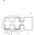
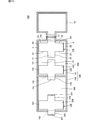
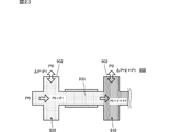
- FIG. 22 is a plan view of a fluid transportation system 900 according to Patent Document 1.
- FIG. FIG. 23 is a cross-sectional view showing a state where the fluid transport system 900 shown in FIG. 22 is discharging air.
- the fluid transport system 900 includes flow paths 931, 933, and 935 and two pumps 910 and 920.
- the pump 910 and the pump 920 have the same configuration.
- the two pumps 910 and 920 are connected in series.
- the flow path 935 is connected to a container, for example.
- the maximum discharge flow rate generated by the two pumps 910 and 920 connected in series is the same as the maximum discharge flow rate generated by the single pump 910.
- the maximum discharge pressure created by two pumps 910 and 920 connected in series is twice the maximum discharge pressure created by one pump 910.
- the maximum discharge pressure generated by the two pumps 910 and 920 connected in series is 2 ⁇ P1.
- the difference between the pressure inside the pump housing and the pressure outside the pump housing increases with the pump connected to the lower stage near the container.
- the differential pressure ⁇ P between the inner pressure P1 + P0 and the outer pressure P0 (atmospheric pressure) in the pump housing is P1
- the low pressure close to the container is low.
- the differential pressure ⁇ P between the inner pressure 2 ⁇ P1 + P0 and the outer pressure P0 (atmospheric pressure) in the pump housing is 2 ⁇ P1.
- the pump housing 902 is easily deformed compared to the pump 920 connected to the high stage side. Therefore, the pump housing 902 may be damaged in the pump 910 connected to the low stage side.
- NPWT Negative Pressure Wound Therapy
- An object of the present invention is to provide a gas control device that can prevent a pump connected to a low stage side from being damaged even when a plurality of pumps are connected in series.
- a gas control device includes a first pump housing having a plurality of outer walls, a first pump having a first suction hole and a first discharge hole provided in the first pump housing, A second pump having a second pump housing, a second suction hole and a second discharge hole provided in the second pump housing; A connection housing that forms a first closed space together with the first pump housing and the second pump housing; The first outer wall provided with at least the first suction hole among the plurality of outer walls faces the first closed space, The second discharge hole and the first suction hole communicate with each other through the first closed space.
- the first discharge hole is connected to the container.
- a gas control device includes a first pump housing having a plurality of outer walls, a first pump having a first suction hole and a first discharge hole provided in the first pump housing, A second pump having a second pump housing, a second suction hole and a second discharge hole provided in the second pump housing; A connection housing that forms a first closed space together with the first pump housing and the second pump housing; The first outer wall provided with at least the first discharge hole among the plurality of outer walls faces the first closed space, The first discharge hole and the second suction hole communicate with each other through the first closed space.
- the first suction hole is connected to the container.
- the gas control device connects the first pump and the second pump in series by the connection housing. Then, at least the first outer wall of the plurality of outer walls faces the first closed space.
- the gas control device sets the pressure difference ⁇ P between the inner pressure and the outer pressure in the first outer wall of the first pump housing to the discharge pressure P1 of the first pump in the first pump on the lower stage side close to the container. Can be suppressed.
- the gas control device can prevent the first pump connected to the low stage side from being damaged. Further, the gas control device does not need to increase the pressure resistance performance by increasing the thickness of the first outer wall. Therefore, the gas control device does not need to increase the size of the first pump or increase the weight of the first pump.
- the load applied to the pump itself refers to the pressure applied to the pump or the density of the fluid.
- the load applied to the pump itself refers to the pressure applied to the pump or the density of the fluid.
- a rotary pump it is desirable that the lower the fluid density, the lower the torque and the higher the rotational speed, while the higher the fluid density, the higher the torque and the lower the rotational speed.
- a diaphragm pump it is desirable to design such that the lower the fluid density, the higher the amplitude and the lower inertia, and the higher the fluid density, the lower the amplitude and the higher the inertia.
- connection housing has higher rigidity. This is because it is possible to suppress the deformation of the casing accompanying the increase in pressure.
- the pump housing that does not face the closed space is substantially the same member. This is because the portion where the pressure resistance is weak in the pump housing is often the joint portion of the constituent members, and when the joint portion faces the closed space, deformation or cracking occurs from that point.
- the present invention can prevent the pump connected to the lower stage from being damaged even when a plurality of pumps are connected in series.
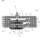
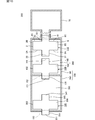
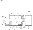
- FIG. 1 is a schematic cross-sectional view of a gas control device 100 according to the first embodiment of the present invention.
- FIG. 2 is a cross-sectional view of the gas control device 100 shown in FIG.
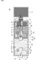
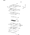
- FIG. 3 is an exploded perspective view of the gas control apparatus 100 shown in FIG. 4 is an exploded perspective view of the gas control apparatus 100 shown in FIG.
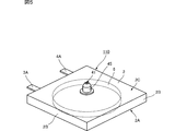
- FIG. 5 is an external perspective view of the first pump 110 shown in FIG.
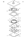
- FIG. 6 is an exploded perspective view of the first pump 110 shown in FIG.
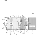
- FIG. 7 is a schematic cross-sectional view of the gas control device 100 while the first pump 110 and the second pump 120 shown in FIG. 1 are discharging air.
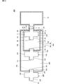
- FIG. 8 is a schematic cross-sectional view of a gas control device 200 according to the second embodiment of the present invention.
- FIG. 8 is a schematic cross-sectional view of a gas control device 200 according to the second embodiment of the present invention.
- FIG. 9 is a schematic cross-sectional view of the gas control device 200 while the first pump 110 and the second pump 120 shown in FIG. 8 are discharging air.
- FIG. 10 is a schematic cross-sectional view of a gas control device 300 according to the third embodiment of the present invention.
- FIG. 11 is a schematic cross-sectional view of the gas control device 300 while the first pump 110, the second pump 120, and the third pump 130 shown in FIG. 10 are discharging air.
- FIG. 12 is a schematic cross-sectional view of a gas control device 400 according to the fourth embodiment of the present invention.
- FIG. 13 is a schematic cross-sectional view of the gas control device 400 while the first pump 110, the second pump 120, and the third pump 130 shown in FIG. 12 are discharging air.
- FIG. 10 is a schematic cross-sectional view of a gas control device 300 according to the third embodiment of the present invention.
- FIG. 11 is a schematic cross-sectional view of the gas control device 300 while the first pump 110, the second
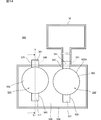
- FIG. 14 is a schematic cross-sectional view of a gas control device 500 according to the fifth embodiment of the present invention.
- 15 is a cross-sectional view taken along line SS shown in FIG.
- FIG. 16 is a schematic cross-sectional view of the gas control device 500 while the first pump 510 and the second pump 520 shown in FIG. 14 are discharging air.
- FIG. 17 is a schematic cross-sectional view of a gas control device 600 according to the sixth embodiment of the present invention.
- FIG. 18 is a schematic cross-sectional view of the gas control device 600 while the first pump 110 and the second pump 120 shown in FIG. 17 are sucking air.
- FIG. 19 is a schematic cross-sectional view of a gas control device 700 according to the seventh embodiment of the present invention.
- FIG. 20 is a schematic cross-sectional view of the gas control device 700 while the first pump 110, the second pump 120, and the third pump 130 shown in FIG. 19 are sucking air.
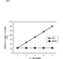
- FIG. 21 is a diagram illustrating an example of the relationship between the number of pumps connected in series and the differential pressure applied to the lowest pump housing.
- FIG. 22 is a plan view of a fluid transportation system 900 according to Patent Document 1.
- FIG. 23 is a cross-sectional view showing a state where the fluid transport system 900 shown in FIG. 22 is discharging air.
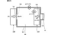
- FIG. 24 is an exploded perspective view of the valve 101. It is a schematic sectional drawing in case the 1st pump provided with the valve
- FIG. 1 is a schematic cross-sectional view of a gas control device 100 according to a first embodiment of the present invention.
- the gas control device 100 includes a first pump 110, a second pump 120, and a connection housing 90.
- the first pump 110 includes a first pump housing 2, a first suction hole 31 and a first discharge hole 41 provided in the first pump housing 2, and a first nozzle that forms the first discharge hole 41 inside. 45 and a first nozzle 35 that forms the first suction hole 31 on the inside.
- the first pump housing 2 has a plurality of outer walls 2A, 2B, 2C.
- the outer wall 2A corresponds to an example of the first outer wall of the present invention
- the outer walls 2B and 2C correspond to an example of the second outer wall of the present invention.
- the second pump 120 includes a second pump housing 102, a second suction hole 131 and a second discharge hole 141 provided in the second pump housing 102, and a second nozzle that forms the second discharge hole 141 on the inside. 145 and a second nozzle 135 that forms the second suction hole 131 on the inside.
- the connection housing 90 has a first opening 191, a second opening 192, a wiring 67 and a wiring 68.
- the connection housing 90 fixes the first pump housing 2 by fitting the first nozzle 45 into the first opening 191. Thereby, the connection housing 90 contacts the first pump 110 only at the first nozzle 45. Therefore, the connection housing 90 does not hinder the vibration of the first pump 110. Therefore, the characteristics of the first pump 110 can be maintained.
- the wiring 68 is connected to a power source (not shown) and is connected to external connection terminals 3A and 4A of the first pump 110 described later.
- connection housing 90 fixes the second pump housing 102 by fitting the second nozzle 145 into the second opening 192. As a result, the connection housing 90 comes into contact with the second pump 120 only at the second nozzle 145. Therefore, the connection housing 90 does not hinder the vibration of the second pump 120. Therefore, the characteristics of the second pump 120 can be maintained.
- the wiring 67 is connected to a power source (not shown) and connected to external connection terminals 3A and 4A of the second pump 120 described later.
- connection housing 90 forms a first closed space 80 together with the first pump housing 2 of the first pump 110 and the second pump housing 102 of the second pump 120.
- the second discharge hole 141 and the first suction hole 31 communicate with each other through the first closed space 80. In this way, the first pump 110 and the second pump 120 are connected in series.
- the first discharge hole 41 communicates with the inside of the container 70.
- the second suction hole 131 is open to the atmosphere.
- a portion other than the first nozzle 45 in the first pump housing 2 faces the first closed space 80. That is, at least the outer wall 2A of the plurality of outer walls 2A, 2B, 2C faces the first closed space 80. Furthermore, out of the plurality of outer walls 2A, 2B, 2C, the outer walls 2B, 2C other than the outer wall 2A also face the first closed space 80.
- FIG. 2 is a cross-sectional view of the gas control device 100 shown in FIG.
- FIG. 3 is an exploded perspective view of the gas control device 100 shown in FIG. 1 as viewed from the upper surface side.
- 4 is an exploded perspective view of the gas control device 100 shown in FIG. 1 as viewed from the lower surface side.
- the connection housing 90 has a structure in which a lid housing 85, a first housing 91, and a second housing 92 are stacked via packings 63 and 64.
- the lid housing 85 has eight bolt holes N0.
- the first housing 91 has eight bolt holes N1.
- the second housing 92 has eight bolt holes N2.
- the lid casing 85, the first casing 91, and the second casing 92 are joined by inserting eight bolts B into the respective bolt holes N0, N1, and N2.
- the lid housing 85 has a connection hole 89 that communicates with the inside of the container 70.
- the first housing 91 has a first opening 191.
- the second housing 92 has a second opening 192.
- the lid housing 85 and the first housing 91 form a closed space 81 that communicates with the connection hole 89 and the first discharge hole 41.
- the first casing 91 fixes the first pump casing 2 by fitting the first nozzle 45 into the first opening 191 via the O-ring 61. Accordingly, the first discharge hole 41 communicates with the inside of the container 70.
- the second casing 92 fixes the second pump casing 102 by fitting the second nozzle 145 into the second opening 192 via the O-ring 62.
- the second suction hole 131 is open to the atmosphere.
- the first housing 91 is provided with a check valve 66.
- the second housing 92 is provided with a check valve 65.
- the check valve 65 or the check valve 66 connected in parallel with the failed pump is opened, and the failed pump Go through. Therefore, the check valve 65 and the check valve 66 can prevent the discharge pressure or suction pressure of the gas control device 100 from becoming 0 kPa.
- the first casing 91 and the second casing 92 form the first closed space 80 together with the first pump casing 2 and the second pump casing 102.
- the second discharge hole 141 and the first suction hole 31 communicate with each other through the first closed space 80.
- connection housing casing 90 has the check valve 65 and the check valve 66 here, it is not restricted to this. In the implementation, the connection housing 90 may not have the check valve 65 and the check valve 66.
- the configuration of the second pump 120 is the same as the configuration of the first pump 110. That is, the configurations of the second pump housing 102, the second suction hole 131, the second discharge hole 141, the second nozzle 135, and the second nozzle 145 in the second pump 120 are the same as the first pump in the first pump 110.
- the configurations of the housing 2, the first suction hole 31, the first discharge hole 41, the first nozzle 35, and the first nozzle 45 are the same. Therefore, the description about the structure of the 2nd pump 120 is abbreviate
- FIG. 5 is an external perspective view of the first pump 110 shown in FIG.
- the first pump 110 includes a first pump housing 2 and external connection terminals 3A and 4A.
- the external connection terminals 3A and 4A are connected to an external power source, and an AC drive signal is applied.
- the first pump housing 2 has a rectangular parallelepiped shape, one outer wall 2A provided with the first suction hole 31, one outer wall 2C provided with the first discharge hole 41, the outer wall 2A and the outer wall 2C. And four outer walls 2B.
- the first pump housing 2 constitutes a pump chamber 6 inside.
- the first pump housing 2 has a first discharge hole 41 that communicates with the pump chamber 6 and a first suction hole 31 (see FIG. 6) that communicates with the pump chamber 6.
- FIG. 6 is an exploded perspective view of the first pump 110 shown in FIG.
- the first pump 110 includes an outer wall 2A, a flow path plate 12, a counter plate 13, a vibration plate 15, a piezoelectric element 16, an insulating plate 17, a power feeding plate 18, and an outer wall 2C, and has a structure in which these are stacked in order. Yes.
- the outer wall 2A is plate-shaped and has three first suction holes 31.
- the flow path plate 12 and the counter plate 13 are formed with flow paths leading to the three first suction holes 31 and the pump chamber 6.
- the diaphragm 15, the insulating plate 17, and the power feeding plate 18 constitute the pump chamber 6 (see FIG. 5).
- a first discharge hole 41 communicating with the pump chamber 6 is formed in the outer wall 2C.
- the flow path plate 12 has one opening 32, three flow paths 33, and six adhesive sealing holes 34.
- the opening 32 is provided at the center position of the flow path plate 12.
- the opening 32 is covered with the outer wall 2A on the lower surface side, and communicates with a flow path hole 132 of the counter plate 13 described later on the upper surface side.
- the three flow paths 33 extend in the radial direction from the openings 32 provided near the center of the flow path plate 12.
- the first end of each flow path 33 communicates with the opening 32.
- the second end of each flow path 33 communicates with each of the three first suction holes 31 in the outer wall 2A.
- Each flow path 33 is covered with the outer wall 2 ⁇ / b> A and the opposing plate 13 at the top and bottom except for the second end.
- the six adhesive sealing holes 34 communicate with the pump chamber 6.
- the adhesive sealing holes 34 are arranged at intervals between each other along the outer periphery of the pump chamber 6 (see FIG. 5).
- Each adhesive sealing hole 34 is covered with the outer wall 2 ⁇ / b> A on the lower surface side, and the upper surface side communicates with an adhesive sealing hole 36 of the counter plate 13 described later.
- the opposing plate 13 is made of metal and includes an external connection terminal 3A so as to protrude outward.
- the counter plate 13 has one flow path hole 132 and six adhesive sealing holes 36.
- the flow path hole 132 is provided in the center of the opposing plate 13 with a diameter smaller than the opening 32 of the flow path plate 12.
- the lower surface side of the flow path hole 132 communicates with the opening 32 of the flow path plate 12, and the upper surface side communicates with the pump chamber 6 (see FIG. 5).
- the six adhesive sealing holes 36 are arranged at intervals between each other along the outer periphery of the pump chamber 6 (see FIG. 5). Each adhesive sealing hole 36 communicates with each adhesive sealing hole 34 of the flow path plate 12.
- the adhesive sealing holes 34 and 36 are holes through which an uncured adhesive used for bonding the counter plate 13 and the vibration plate 15 flows.
- the adhesive sealing holes 34 and 36 prevent the uncured adhesive from protruding into the pump chamber 6 (see FIG. 5) and adhering to the connecting portion 23 of the diaphragm 15.
- the diaphragm 15 that is the first diaphragm (or the second diaphragm) is a metal plate such as SUS.
- the diaphragm 15 includes a disk portion 21, a frame portion 22, and three connecting portions 23.
- the diaphragm 15 has a plurality of openings 37 surrounded by the disk portion 21, the frame portion 22, and the connecting portion 23.
- the plurality of openings 37 constitute a part of the pump chamber 6 (see FIG. 5).
- the disc part 21 has a circular shape in plan view.
- the frame portion 22 has a frame shape in which a circular opening is provided in plan view, and surrounds the periphery of the disc portion 21 with a space therebetween.
- Each connecting portion 23 connects the disc portion 21 and the frame portion 22.
- the disc part 21 is supported by the connecting part 23 in a state of floating inside the pump chamber 6 (see FIG. 5).
- the piezoelectric element 16 which is the first piezoelectric body (or the second piezoelectric body) is configured by providing electrodes on the upper and lower surfaces of a disk made of a piezoelectric material.
- the electrode on the upper surface of the piezoelectric element 16 is electrically connected to the external connection terminal 4 ⁇ / b> A via the power supply plate 18.
- the electrode on the lower surface of the piezoelectric element 16 is electrically connected to the external connection terminal 3 ⁇ / b> A via the vibration plate 15 and the counter plate 13.
- the piezoelectric element 16 and the disc part 21 are pasted via an adhesive or the like (not shown) to constitute a vibrating part 24.
- the vibration part 24 has a unimorph structure of the piezoelectric element 16 and the disk part 21, and is configured such that bending vibration in the vertical direction is generated when the expansion and contraction of the piezoelectric element 16 is restricted by the disk part 21.
- the insulating plate 17 has a frame shape having a circular opening 38 in plan view.
- the opening 38 constitutes a part of the pump chamber 6 (see FIG. 5).
- the insulating plate 17 is made of an insulating resin and electrically insulates between the power feeding plate 18 and the diaphragm 15.
- the power feeding plate 18 is made of metal.
- the power feeding plate 18 includes an external connection terminal 4 ⁇ / b> A and an internal connection terminal 27, and has an opening 39 surrounded by a support portion 29.
- the internal connection terminal 27 is in contact with the electrode on the upper surface of the piezoelectric element 16.
- the outer wall 2C has a plate shape and covers the upper surface of the pump chamber 6 (see FIG. 5).
- the outer wall 2 ⁇ / b> C has a first discharge hole 41.
- the first discharge hole 41 communicates with the pump chamber 6.
- the first nozzle 35 may be attached to the first suction hole 31.
- FIG. 7 is a schematic cross-sectional view of the gas control device 100 while the first pump 110 and the second pump 120 shown in FIG. 1 are discharging air.
- a unidirectional arrow in FIG. 7 indicates the flow of air.
- a double-directional arrow in FIG. 7 indicates a differential pressure.
- the hatching density in FIG. 7 indicates the magnitude of the pressure.
- the air is sucked from the second suction hole 131 of the second pump 120 and flows into the first closed space 80 from the second discharge hole 141.
- the air is sucked from the first suction hole 31 of the first pump 110 and flows into the container 70 from the first discharge hole 41. Thereby, the pressure in the container 70 becomes high.
- the maximum discharge flow rate generated by the two first pumps 110 and the second pump 120 connected in series is the same as the maximum discharge flow rate generated by the one first pump 110.
- each of the first pump 110 and the second pump 120 generates the discharge pressure P ⁇ b> 1, so that the two first pumps 110 and the second pump 120 connected in series generate each other.
- the maximum discharge pressure is 2 ⁇ P1.
- the differential pressure ⁇ P between the inner pressure P1 + P0 and the outer pressure P0 (atmospheric pressure) in the pump housing is P1
- the container In the low-stage pump 910 close to 70 the differential pressure ⁇ P between the inner pressure 2 ⁇ P1 + P0 and the outer pressure P0 (atmospheric pressure) in the pump housing is 2 ⁇ P1.
- the gas control device 100 connects the first pump 110 and the second pump 120 in series by the connection housing 90.
- at least the outer wall 2 ⁇ / b> A of the plurality of outer walls 2 ⁇ / b> A, 2 ⁇ / b> B, 2 ⁇ / b> C faces the first closed space 80.
- the differential pressure ⁇ P between the inner pressure P1 + P0 and the outer pressure P0 (atmospheric pressure) in the connection housing 90 is P1.
- the differential pressure ⁇ P between the inner pressure 2 ⁇ P1 + P0 and the outer pressure P1 + P0 in the outer wall 2A of the first pump housing 2 is P1.
- the differential pressure ⁇ P between the inner pressure P1 + P0 and the outer pressure P0 in the second pump housing 102 is P1.
- the gas control apparatus 100 suppresses the differential pressure ⁇ P between the inner pressure and the outer pressure in the first pump housing 2 of the lowest-stage first pump 110 to be equal to or lower than the discharge pressure P1 of the first pump 110. be able to.
- the gas control device 100 can prevent the first pump 110 connected to the low stage side from being damaged. Further, the gas control device 100 does not need to increase the pressure resistance performance by increasing the thickness of the first pump housing 2. Therefore, the gas control device 100 does not need to increase the size of the first pump 110 or increase the weight of the first pump 110.
- the outer walls 2B, 2C other than the outer wall 2A among the plurality of outer walls 2A, 2B, 2C also face the first closed space 80. Therefore, the gas control apparatus 100 can further prevent the first pump 110 connected to the low stage side from being damaged even when a plurality of pumps are connected in series.
- the differential pressure ⁇ P between the inner pressure P1 + P0 and the outer pressure P1 + P0 in the second nozzle 145 is zero. Therefore, in the gas control device 100, the air inside the connection housing 90 is unlikely to flow out of the second pump housing 102 through the gap between the second nozzle 145 and the second pump housing 102.
- FIG. 8 is a schematic cross-sectional view of a gas control device 200 according to the second embodiment of the present invention.
- FIG. 9 is a schematic cross-sectional view of the gas control device 200 while the first pump 110 and the second pump 120 shown in FIG. 8 are discharging air.
- a unidirectional arrow in FIG. 9 indicates the flow of air.
- a double-directional arrow in FIG. 9 indicates a differential pressure.
- the hatching density in FIG. 9 indicates the magnitude of the pressure.
- connection housing 90 fixes the second pump housing 102 by fitting the second nozzle 135 into the second opening 192. Since other configurations are the same, description thereof is omitted.
- connection housing 90 forms a first closed space 280 together with the first pump housing 2 and the second pump housing 102.
- the second discharge hole 141 and the first suction hole 31 communicate with each other through the first closed space 280.
- the gas control apparatus 200 connects the first pump 110 and the second pump 120 in series by the connection housing 90. Further, with respect to the first pump 110, a portion other than the first nozzle 45 in the first pump housing 2 faces the first closed space 280.
- the outer wall 2A among the plurality of outer walls 2A, 2B, 2C faces the first closed space 280. Furthermore, out of the plurality of outer walls 2A, 2B, 2C, the outer walls 2B, 2C other than the outer wall 2A also face the first closed space 280.
- the differential pressure ⁇ P between the inner pressure P1 + P0 and the outer pressure P0 (atmospheric pressure) in the connection housing 90 is P1.
- the differential pressure ⁇ P between the inner pressure 2 ⁇ P1 + P0 and the outer pressure P1 + P0 on the outer walls 2A, 2B, 2C of the first pump housing 2 is P1.
- the differential pressure ⁇ P between the inner pressure P1 + P0 and the outer pressure P1 + P0 in the second pump housing 102 is zero.
- the gas control apparatus 200 suppresses the differential pressure ⁇ P between the inner pressure and the outer pressure in the first pump housing 2 of the lowest-stage first pump 110 to be equal to or lower than the discharge pressure P1 of the first pump 110. be able to.
- the gas control device 200 can prevent the first pump 110 connected to the low stage side from being damaged even when a plurality of pumps are connected in series. Further, similarly to the gas control device 100, the gas control device 200 does not need to increase the size of the first pump 110 or increase the weight of the first pump 110.
- the gas control device 200 includes the wiring 67 inside the connection housing 90. Therefore, the gas control device 200 is less likely to be disconnected than the gas control device 100, and can improve reliability.
- the differential pressure ⁇ P between the inner pressure P0 and the outer pressure P1 in the second nozzle 135 is P1. Therefore, in the gas control device 200, the air inside the connection housing 90 easily flows out of the second pump housing 102 from the gap between the second nozzle 135 and the second pump housing 102 compared to the gas control device 100. .
- FIG. 10 is a schematic cross-sectional view of a gas control device 300 according to the third embodiment of the present invention.
- FIG. 11 is a schematic cross-sectional view of the gas control device 300 while the first pump 110, the second pump 120, and the third pump 130 shown in FIG. 10 are discharging air.
- a unidirectional arrow in FIG. 11 indicates the flow of air.
- a double arrow in FIG. 11 indicates a differential pressure.
- the hatching density in FIG. 11 indicates the magnitude of the pressure. 10 and 11, illustration of wiring is omitted.
- the difference between the gas control device 300 and the gas control device 100 shown in FIG. 1 is that a third pump 130 and a connection housing 390 are provided. Since other configurations are the same, description thereof is omitted.
- the third pump 130 includes a third pump housing 302, a third suction hole 331 and a third discharge hole 341 provided in the third pump housing 302, and a third nozzle that forms the third discharge hole 341 on the inside. 345 and a third nozzle 335 that forms a third suction hole 331 on the inside.
- the configuration of the third pump 130 is the same as the configuration of the first pump 110, and thus the description thereof is omitted.
- connection housing 390 is configured by joining the connection housing 290 formed with the third opening 193 and the connection housing 90 together. Thereby, the connection housing 390 has the third opening 193.
- connection housing 390 fixes the third pump housing 302 by fitting the third nozzle 335 into the third opening 193. As a result, the connection housing 390 comes into contact with the third pump 130 only at the third nozzle 335. Therefore, the connection housing 390 does not hinder the vibration of the third pump 130. Therefore, the gas control device 300 can maintain the characteristics of the third pump 130.
- the connection housing 390 forms a first closed space 280 and a second closed space 380 together with the first pump housing 2, the second pump housing 102, and the third pump housing 302.
- the second discharge hole 141 and the first suction hole 31 communicate with each other through the first closed space 280.
- the third discharge hole 341 and the second suction hole 131 communicate with each other through the second closed space 380.
- the third suction hole 331 is open to the atmosphere. Since other configurations are the same, description thereof is omitted.
- the maximum discharge flow rate generated by the three first pumps 110, the second pump 120, and the third pump 130 connected in series is the same as the maximum discharge flow rate generated by the one first pump 110.
- each of the first pump 110, the second pump 120, and the third pump 130 generates three discharge pressures P ⁇ b> 1, and the three first pumps 110 and the second pumps connected in series.
- the maximum discharge pressure created by the pump 120 and the third pump 130 is 3 ⁇ P1.
- the gas control device 300 connects the first pump 110, the second pump 120, and the third pump 130 in series by the connection housing 390. Further, with respect to the first pump 110, a portion other than the first nozzle 45 in the first pump housing 2 faces the first closed space 280.
- the outer wall 2A among the plurality of outer walls 2A, 2B, 2C faces the first closed space 280. Furthermore, out of the plurality of outer walls 2A, 2B, 2C, the outer walls 2B, 2C other than the outer wall 2A also face the first closed space 280.
- the differential pressure ⁇ P between the inner pressure 3 ⁇ P1 + P0 and the outer pressure 2 ⁇ P1 + P0 on the outer walls 2A, 2B, 2C of the first pump housing 2 is P1.
- the differential pressure ⁇ P between the inner pressure 2 ⁇ P1 + P0 and the outer pressure 2 ⁇ P1 + P0 in the second pump housing 102 is zero.
- the differential pressure ⁇ P between the inner pressure P1 + P0 and the outer pressure P1 + P0 in the third pump housing 302 is zero.
- the gas control apparatus 300 suppresses the pressure difference ⁇ P between the inner pressure and the outer pressure in the first pump housing 2 of the lowest-stage first pump 110 to be equal to or lower than the discharge pressure P1 of the first pump 110. be able to.
- the gas control device 300 can prevent the first pump 110 connected to the low stage side from being damaged even when a plurality of pumps are connected in series. Further, like the gas control device 100, the gas control device 300 does not need to increase the size of the first pump 110 or increase the weight of the first pump 110.
- connection housing 390 is constituted by the connection housing 290 and the connection housing 90. Therefore, the gas control device 300 attaches the first pump 110 and the second pump 120 to the connection housing 90 provided with wiring, and attaches the third pump 130 to the connection housing 290 provided with wiring.
- the connection case 90 and the connection case 290 are joined together. Therefore, the gas control apparatus 300 can easily connect the first pump 110, the second pump 120, and the third pump 130 in series by the connection housing 390.
- FIG. 12 is a schematic cross-sectional view of a gas control device 400 according to the fourth embodiment of the present invention.
- FIG. 13 is a schematic sectional view of the gas control device 400 while the first pump 110, the second pump 120, and the third pump 130 shown in FIG. 12 are discharging air.
- a unidirectional arrow in FIG. 13 indicates the flow of air.
- a double arrow in FIG. 13 indicates a differential pressure.
- the hatching density in FIG. 13 indicates the magnitude of the pressure.
- illustration of wiring is omitted.
- connection housing 490 is configured by joining the connection housing 491 in which the third opening 193 is formed and the connection housing 90. Thereby, the connection housing 490 has the third opening 193.
- connection housing 490 forms a first closed space 80 and a second closed space 480 together with the first pump housing 2, the second pump housing 102, and the third pump housing 302.
- the second discharge hole 141 and the first suction hole 31 communicate with each other through the first closed space 80.
- the third discharge hole 341 and the second suction hole 131 communicate with each other through the second closed space 480.
- the gas control device 400 connects the first pump 110, the second pump 120, and the third pump 130 in series by the connection housing 490. Further, with respect to the first pump 110, a portion other than the first nozzle 45 in the first pump housing 2 faces the first closed space 80.
- At least the outer wall 2A of the plurality of outer walls 2A, 2B, 2C faces the first closed space 80. Furthermore, out of the plurality of outer walls 2A, 2B, 2C, the outer walls 2B, 2C other than the outer wall 2A also face the first closed space 80.
- the differential pressure ⁇ P between the inner pressure 3 ⁇ P1 + P0 and the outer pressure 2 ⁇ P1 + P0 on the outer walls 2A, 2B, 2C of the first pump housing 2 is P1.
- the differential pressure ⁇ P between the inner pressure 2 ⁇ P1 + P0 and the outer pressure P1 + P0 in the second pump housing 102 is P1.
- the differential pressure ⁇ P between the inner pressure P1 + P0 and the outer pressure P0 in the third pump housing 302 is P1.
- the gas control apparatus 400 suppresses the pressure difference ⁇ P between the inner pressure and the outer pressure in the first pump housing 2 of the lowest-stage first pump 110 to be equal to or lower than the discharge pressure P1 of the first pump 110. be able to.
- the gas control device 400 can prevent the first pump 110 connected to the low stage side from being damaged even when a plurality of pumps are connected in series. Further, similarly to the gas control device 100, the gas control device 400 does not need to increase the size of the first pump 110 or increase the weight of the first pump 110.
- connection housing 490 includes a connection housing 491 and a connection housing 90. Therefore, the gas control device 400 attaches the first pump 110 and the second pump 120 to the connection housing 90 provided with wiring, and attaches the third pump 130 to the connection housing 491 provided with wiring. However, it is manufactured by joining the connection housing 90 and the connection housing 491. Therefore, the gas control device 400 can easily connect the first pump 110, the second pump 120, and the third pump 130 in series by the connection housing 490.
- FIG. 14 is a schematic cross-sectional view of a gas control device 500 according to the fifth embodiment of the present invention.
- 15 is a cross-sectional view taken along line SS shown in FIG.
- FIG. 16 is a schematic cross-sectional view of the gas control device 500 while the first pump 510 and the second pump 520 shown in FIG. 14 are discharging air.
- a unidirectional arrow in FIG. 16 indicates the flow of air.
- a double arrow in FIG. 16 indicates a differential pressure.
- the hatching density in FIG. 16 indicates the magnitude of the pressure.
- the gas control device 500 is different from the gas control device 100 shown in FIG. 1 in the shapes of the first pump 510, the second pump 520, and the connection housing 590.
- the first pump 510 includes a first pump 110, a first pump housing 502, a first suction hole 531 and a first discharge hole provided in the first pump housing 502. 541, a first nozzle 545 that forms the first discharge hole 541 on the inside, and a first nozzle 535 that forms the first suction hole 531 on the inside.
- the first pump housing 502 is cylindrical and has a plurality of outer walls 502A and 502B.
- the outer wall 502 ⁇ / b> A has a first suction hole 531.
- the first pump housing 502 has a fixing portion 595.
- the first pump housing 502 fixes the first pump housing 2 of the first pump 110 inside by a fixing portion 595. Accordingly, the first pump housing 502 communicates with the first pump housing 2, the closed space 506 that communicates with the first suction hole 31 and the first suction hole 531, and the first discharge hole 41 and the first discharge hole 541.
- a closed space 507 is formed.
- the second pump 520 includes the first pump 110, the second pump housing 552, the second suction hole 561 and the second discharge hole 571 provided in the second pump housing 552, and the second discharge hole 571 inside. And a second nozzle 165 that forms a second suction hole 561 on the inner side.
- the configuration of the second pump 520 is the same as the configuration of the first pump 510. That is, the configurations of the second pump casing 552, the second suction hole 561, the second discharge hole 571, the second nozzle 575, and the second nozzle 165 are the same as the first pump casing 502, the first suction hole 531, and The configuration of each of the first discharge hole 541, the first nozzle 545, and the first nozzle 535 is the same.
- the connection housing 590 has a first opening 591 and a second opening 592.
- the connection housing 590 fixes the first pump housing 502 by fitting the first nozzle 545 into the first opening 591. Thereby, the connection housing 590 comes into contact with the first pump 110 only at the first nozzle 545. Therefore, the connection housing 590 does not hinder the vibration of the first pump 110. Therefore, the gas control device 500 can maintain the characteristics of the first pump 110.
- connection housing 590 fixes the second pump housing 552 by fitting the second nozzle 575 into the second opening 592. Thereby, the connection housing 590 comes into contact with the first pump 110 only at the second nozzle 575. Therefore, the connection housing 590 does not hinder the vibration of the first pump 110. Therefore, the gas control device 500 can maintain the characteristics of the first pump 110.
- connection housing 590 forms a first closed space 580 together with the first pump housing 502 and the second pump housing 552.
- the second discharge hole 571 and the first suction hole 531 communicate with each other through the first closed space 580.
- the first discharge hole 541 communicates with the inside of the container 70.
- the second suction hole 561 is open to the atmosphere.
- the gas control device 500 connects the first pump 510 and the second pump 520 in series by the connection housing 590. Further, with respect to the first pump 510, a portion other than the first nozzle 545 in the first pump housing 502 faces the first closed space 580.
- At least the outer wall 502A of the plurality of outer walls 502A and 502B faces the first closed space 80. Further, among the plurality of outer walls 502A and 502B, the outer wall 502B other than the outer wall 502A also faces the first closed space 580.
- the gas control device 500 can prevent the first pump 510 connected to the low stage side from being damaged even when a plurality of pumps are connected in series. Further, similarly to the gas control device 100, the gas control device 500 does not need to increase the size of the first pump 510 or increase the weight of the first pump 510.
- first pump and the second pump do not need to have nozzles.
- a valve as shown in FIG. 24 can be used instead of the nozzle.
- FIG. 24 is an exploded perspective view of the valve 101.
- the valve 101 includes an edge cut plate 199, a first plate 1910 provided with a first vent hole 1100 and a first vent hole 111, a frame plate 195, a diaphragm 1200 made of a rectangular thin film, and a rectangular thin film. And a second plate 1920 provided with the second ventilation hole 112, and has a structure in which these are sequentially laminated.
- the flow path forming plate 1930, the intermediate plate 194, and the frame plate 195 constitute a side wall plate 190.
- the flow path forming plate 1930 forms an exhaust flow path 114 that communicates with the exhaust holes 113.
- the material of the edge cut plate 199 is, for example, PET resin.
- the material of the first plate 1910, the side wall plate 190, and the second plate 1920 is, for example, metal.
- Each joining of the 2nd board 1920, the flow-path formation board 1930, the intermediate board 194, the frame board 195, and the 1st board 1910 is performed by a double-sided tape, thermal diffusion joining, or an adhesive agent, for example.
- the second plate 1920 has a second ventilation hole 112 communicating with the cuff 109 and a valve seat 139 located around the exhaust passage 114 communicating with the exhaust hole 113.
- the second plate 1920 is made of resin, for example.
- the first plate 1910 has a first vent hole 1100 communicating with the discharge hole 56 of the pump 10 and a first vent hole 111 communicating with the discharge hole 55 of the pump 10.
- the first plate 1910 is made of metal, for example.
- the diaphragm 1200 is provided with a circular hole 121 at the center of the region facing the valve seat 138.
- the diameter of the hole 121 is smaller than the diameter of the surface of the valve seat 138 that contacts the diaphragm 1200.
- the outer periphery of the diaphragm 1200 is smaller than the outer periphery of each of the first plate 1910 and the second plate 1920.
- the diaphragm 1200 is made of rubber such as EPDM (ethylene propylene diene rubber) or silicone.
- the diaphragm 1200 is sandwiched between the first plate 1910 and the intermediate plate 194 via the sealing material 152. As a result, a part of the diaphragm 1200 contacts the valve seat 139 and the periphery of the hole 121 in the diaphragm 1200 contacts the valve seat 138.
- the valve seat 138 is provided on the first plate 1910 so as to pressurize the periphery of the hole 121 in the diaphragm 1200.
- the valve seat 138 includes a protrusion 138A and a protrusion 138B.
- the material of the protrusion 138A and the protrusion 138B is, for example, a metal.
- Diaphragm 1200 divides the space formed by second plate 1920 and first plate 1910 into a first valve chamber and a second valve chamber.
- the diameter of each of the first valve chamber and the second valve chamber is, for example, 7.0 mm.
- the diameter of the surface of the valve seat 138 that contacts the diaphragm 1200 is, for example, 1.5 mm.
- the sealing material 152 is made of, for example, a double-sided tape or an adhesive.
- a check valve is constituted by the periphery of the hole 121 in the diaphragm 1200 and the valve seat 138 that contacts the periphery and covers the hole 121.
- the diaphragm 120 contacts or separates from the valve seat 138 based on the pressure in the first valve chamber and the pressure in the second valve chamber.
- the exhaust valve 170 includes a part of the diaphragm 120 and a valve seat 139 located around the exhaust flow path 114.
- a part of the diaphragm 120 contacts or separates from the valve seat 139 based on the pressure in the first valve chamber and the pressure in the second valve chamber.
- the inner pressure and the outer pressure on the first outer wall of the first pump housing can be obtained by using the first pump and the second pump provided with the valve 101 as described above instead of the nozzle. Can be suppressed to the discharge pressure P1 of the first pump.
- FIG. 17 is a schematic cross-sectional view of a gas control device 600 according to the sixth embodiment of the present invention.
- the gas control device 600 is different from the gas control device 100 shown in FIG. 1 in that the first pump 110 and the second pump 120 are fixed to the connection housing 90 in the opposite direction.
- the first suction hole 31 is connected to the container 70 and communicates with the container 70.
- the first discharge hole 41 and the second suction hole 131 communicate with each other through the first closed space 80. Since other configurations are the same, description thereof is omitted.
- the outer wall 2C corresponds to an example of the first outer wall of the present invention
- the outer walls 2A and 2B correspond to an example of the second outer wall of the present invention.
- FIG. 18 is a schematic cross-sectional view of the gas control device 600 while the first pump 110 and the second pump 120 shown in FIG. 17 are sucking air.
- a unidirectional arrow in FIG. 18 indicates the flow of air.
- a double-directional arrow in FIG. 18 indicates a differential pressure.
- the hatching density in FIG. 18 indicates the magnitude of the pressure.
- the air in the container 70 is sucked from the first suction hole 31 of the first pump 110, and from the first discharge hole 41 to the first closed space. 80. Then, the air in the first closed space 80 is sucked from the second suction hole 131 of the second pump 120 and flows out of the second pump housing 102 from the second discharge hole 141. Thereby, the pressure in the container 70 becomes low.
- the maximum suction flow rate generated by the two first pumps 110 and the second pump 120 connected in series is the same as the maximum suction flow rate generated by the one first pump 110.
- each of the first pump 110 and the second pump 120 generates the suction pressure P ⁇ b> 1, so that the two first pumps 110 and the second pump 120 connected in series generate.
- the maximum suction pressure is 2 ⁇ P1.
- the gas control device 600 connects the first pump 110 and the second pump 120 in series by the connection housing 90. Further, with respect to the first pump 110, a portion other than the first nozzle 35 in the first pump housing 2 faces the first closed space 80.
- At least the outer wall 2C of the plurality of outer walls 2A, 2B, 2C faces the first closed space 80. Furthermore, out of the plurality of outer walls 2A, 2B, 2C, the outer walls 2A, 2B other than the outer wall 2C also face the first closed space 80.
- the differential pressure ⁇ P between the inner pressure P0-P1 and the outer pressure P0 (atmospheric pressure) in the connection housing 90 is P1.
- the differential pressure ⁇ P between the inner pressure P0-P1 and the outer pressure P0 in the second pump housing 102 is P1.
- the differential pressure ⁇ P between the inner pressure P0-2 ⁇ P1 and the outer pressure P0-P1 at the outer walls 2A, 2B, 2C of the first pump housing 2 is P1. is there.
- the gas control device 600 suppresses the differential pressure ⁇ P between the inner pressure and the outer pressure in the first pump housing 2 of the lowest-stage first pump 110 to be equal to or lower than the suction pressure P1 of the first pump 110. be able to.
- the gas control device 600 can prevent the first pump 110 connected to the low stage side from being damaged even when a plurality of pumps are connected in series. Further, similarly to the gas control device 100, the gas control device 600 does not need to increase the size of the first pump 110 or increase the weight of the first pump 110.
- the second pump 120 may be arranged inside the connection housing 90 as in the gas control device 200 shown in FIG.
- FIG. 19 is a schematic cross-sectional view of a gas control device 700 according to the seventh embodiment of the present invention.
- the gas control device 700 is different from the gas control device 300 shown in FIG. 10 in that the first pump 110, the second pump 120, and the third pump 130 are fixed to the connection housing 390 in the opposite direction.
- the first suction hole 31 is connected to the container 70 and communicates with the container 70.
- the first discharge hole 41 and the second suction hole 131 communicate with each other through the first closed space 280.
- the second discharge hole 141 and the third suction hole 331 communicate with each other through the first closed space 280. Since other configurations are the same, description thereof is omitted.
- the outer wall 2C corresponds to an example of the first outer wall of the present invention
- the outer walls 2A and 2B correspond to an example of the second outer wall of the present invention.
- FIG. 20 is a schematic cross-sectional view of the gas control device 700 while the first pump 110, the second pump 120, and the third pump 130 shown in FIG. 19 are sucking air.
- a unidirectional arrow in FIG. 20 indicates the flow of air.
- a double arrow in FIG. 20 indicates a differential pressure.
- the hatching density in FIG. 20 indicates the magnitude of the pressure.
- the air in the container 70 is sucked from the first suction hole 31 of the first pump 110 and from the first discharge hole 41. It flows into the first closed space 280.
- the air in the first closed space 280 is sucked from the second suction hole 131 of the second pump 120 and flows into the second closed space 380 from the second discharge hole 141.
- the air in the second closed space 380 is sucked from the third suction hole 331 of the third pump 130 and flows out of the third pump housing 302 from the third discharge hole 341. Thereby, the pressure in the container 70 becomes low.
- the maximum suction flow rate generated by the three first pumps 110, the second pump 120, and the third pump 130 connected in series is the same as the maximum suction flow rate generated by the one first pump 110.
- each of the first pump 110, the second pump 120, and the third pump 130 generates three suction pressures P1, and the three first pumps 110 and the second pumps connected in series.
- the maximum suction pressure created by the pump 120 and the third pump 130 is 3 ⁇ P1.
- the first pump 110, the second pump 120, and the third pump 130 are connected in series by the connection housing 390. Further, with respect to the first pump 110, a portion other than the first nozzle 45 in the first pump housing 2 faces the first closed space 280.
- the outer wall 2C in which at least the first discharge hole 41 is provided among the plurality of outer walls 2A, 2B, 2C faces the first closed space 280. Furthermore, out of the plurality of outer walls 2A, 2B, 2C, the outer walls 2A, 2B other than the outer wall 2C also face the first closed space 280.
- the differential pressure ⁇ P between the inner pressure P0-3 ⁇ P1 and the outer pressure P0-2 ⁇ P1 on the outer walls 2A, 2B, 2C of the first pump housing 2 is P1.
- the differential pressure ⁇ P between the inner pressure P0-2 ⁇ P1 and the outer pressure P0-2 ⁇ P1 in the second pump housing 102 is zero.
- the differential pressure ⁇ P between the inner pressure P0-P1 and the outer pressure P0-P1 in the third pump housing 302 is zero.
- the gas control apparatus 700 suppresses the pressure difference ⁇ P between the inner pressure and the outer pressure in the first pump housing 2 of the lowest-stage first pump 110 to be equal to or lower than the suction pressure P1 of the first pump 110. be able to.
- the gas control device 700 can prevent the first pump 110 connected to the low stage side from being damaged even when a plurality of pumps are connected in series. Further, similarly to the gas control device 100, the gas control device 700 does not need to increase the size of the first pump 110 or increase the weight of the first pump 110.
- FIG. 21 is a diagram showing an example of the relationship between the number of pumps connected in series and the differential pressure applied to the lowest pump housing.
- the gas control devices 100 to 700 of the present embodiment provide the differential pressure ⁇ P between the inner pressure and the outer pressure in the lowest pump side first pump housing 2,
- the discharge pressure P1 of the first pump 110 can be suppressed below.
- O-ring 63 ... packing 65, 66 ... check valve 67, 68 ... wiring 70 ... container 80, 280, 580 ... first closed space 81 ... closed space 85 ... lid housing 89 ... connection holes 90, 290, 390, 490, 491, 590 ... connection housing 91 ... first housing 92 ... second housings 100, 200, 300 , 400, 500, 600, 700 ... gas control device 102 ... second Pump housing 110 ... first pump 120 ... second pump 130 ... third pump 131 ... second suction hole 132 ... channel hole 135 ... second nozzle 141 ... second discharge hole 145 ... second nozzle 165 ... second nozzle 191 ... 1st opening 192 ... 2nd opening 193 ...
Landscapes
- Engineering & Computer Science (AREA)
- Mechanical Engineering (AREA)
- General Engineering & Computer Science (AREA)
- Reciprocating Pumps (AREA)
- Compressor (AREA)
- Structures Of Non-Positive Displacement Pumps (AREA)
Abstract
気体制御装置(100)は第1ポンプ(110)と第2ポンプ(120)と接続筐体(90)とを備える。第1ポンプ(110)は第1ポンプ筐体(2)と第1吸引孔(31)と第1吐出孔(41)とを有している。第1ポンプ筐体(2)は複数の外壁(2A、2B、2C)を有する。第2ポンプ(120)は第2ポンプ筐体(102)と第2吸引孔(131)と第2吐出孔(141)とを有する。接続筐体(90)は第1開口部(191)と第2開口部(192)とを有している。接続筐体(90)は第1ポンプ筐体(2)及び第2ポンプ筐体(102)とともに第1閉鎖空間(80)を形成する。第2吐出孔(141)と第1吸引孔(31)とは第1閉鎖空間(80)を介して通じている。第1ポンプ(110)と第2ポンプ(120)とは直列に接続されている。第1吸引孔(31)が設けられている外壁(2A)は第1閉鎖空間(80)に面している。
Description
本発明は、気体を輸送する気体制御装置に関するものである。
従来、気体を輸送する気体制御装置が広く使用されている。例えば特許文献1は、空気を輸送する流体輸送システム900を開示している。
図22は、特許文献1に係る流体輸送システム900の平面図である。図23は、図22に示す流体輸送システム900が空気を吐出している様子を示す断面図である。流体輸送システム900は、流路931、933、935と、2個のポンプ910、920とを備えている。ポンプ910とポンプ920とは、同じ構成を有している。流体輸送システム900において2個のポンプ910、920は、直列に接続されている。流路935は例えば容器に接続する。
以上の構成において、図23に示すように2個のポンプ910、920が空気を吐出している間、空気は流路931から流路933を介して流路935へ流れ、容器に流入する。これにより容器内の圧力が高くなる。一方、2個のポンプ910、920が空気を吸引している間、容器内部の空気は流路935から流路933を介して流路931へ流れる。これにより容器内の圧力が低くなる。
ここで、直列に接続された2個のポンプ910、920が作り出す最大吐出流量は、1個のポンプ910が作り出す最大吐出流量と同じである。一方、直列に接続された2個のポンプ910、920が作り出す最大吐出圧力は、1個のポンプ910が作り出す最大吐出圧力の2倍の圧力である。例えば図23に示すように、ポンプ910、920のそれぞれは、吐出圧力P1を作り出すため、直列に接続された2個のポンプ910、920が作り出す最大吐出圧力は、2×P1となる。
しかしながら、複数個のポンプが直列に接続した場合、容器に近い低段側に接続されているポンプではポンプ筐体の内側の圧力と外側の圧力との差が増加する。例えば図23に示すように、高段側のポンプ920ではポンプ筐体における内側の圧力P1+P0と外側の圧力P0(大気圧)との差圧ΔPがP1であるのに対して、容器に近い低段側のポンプ910ではポンプ筐体における内側の圧力2×P1+P0と外側の圧力P0(大気圧)との差圧ΔPが2×P1である。
そのため、低段側に接続されているポンプ910では高段側に接続されているポンプ920に比べて、ポンプ筐体902が変形し易い。よって、低段側に接続されているポンプ910ではポンプ筐体902が破損する可能性がある。
そこで、ポンプ筐体902の厚みを厚くし、耐圧性能を高める方法も考えられるが、この方法ではポンプ910が大型化したりポンプ910の重量が増加したりするという問題がある。
特に手首式血圧計またはNPWT(Negative Pressure Wound Therapy)のように携行性が求められる機器では、ポンプが大型化すると利便性を損なう。
本発明の目的は、複数個のポンプが直列に接続した場合でも、低段側に接続されているポンプが破損することを防止できる気体制御装置を提供することにある。
(1)本発明の気体制御装置は、複数の外壁を有する第1ポンプ筐体と、第1ポンプ筐体に設けられた第1吸引孔及び第1吐出孔とを有する第1ポンプと、
第2ポンプ筐体と、第2ポンプ筐体に設けられた第2吸引孔及び第2吐出孔とを有する第2ポンプと、
第1ポンプ筐体及び第2ポンプ筐体とともに第1閉鎖空間を形成する接続筐体と、を備え、
複数の外壁のうち少なくとも第1吸引孔が設けられている第1外壁は、第1閉鎖空間に面し、
第2吐出孔と第1吸引孔とは、第1閉鎖空間を介して通じている。
第2ポンプ筐体と、第2ポンプ筐体に設けられた第2吸引孔及び第2吐出孔とを有する第2ポンプと、
第1ポンプ筐体及び第2ポンプ筐体とともに第1閉鎖空間を形成する接続筐体と、を備え、
複数の外壁のうち少なくとも第1吸引孔が設けられている第1外壁は、第1閉鎖空間に面し、
第2吐出孔と第1吸引孔とは、第1閉鎖空間を介して通じている。
この構成において例えば第1吐出孔は容器に接続される。
(2)本発明の気体制御装置は、複数の外壁を有する第1ポンプ筐体と、第1ポンプ筐体に設けられた第1吸引孔及び第1吐出孔とを有する第1ポンプと、
第2ポンプ筐体と、第2ポンプ筐体に設けられた第2吸引孔及び第2吐出孔とを有する第2ポンプと、
第1ポンプ筐体及び第2ポンプ筐体とともに第1閉鎖空間を形成する接続筐体と、を備え、
複数の外壁のうち少なくとも第1吐出孔が設けられている第1外壁は、第1閉鎖空間に面し、
第1吐出孔と第2吸引孔とは、第1閉鎖空間を介して通じている。
第2ポンプ筐体と、第2ポンプ筐体に設けられた第2吸引孔及び第2吐出孔とを有する第2ポンプと、
第1ポンプ筐体及び第2ポンプ筐体とともに第1閉鎖空間を形成する接続筐体と、を備え、
複数の外壁のうち少なくとも第1吐出孔が設けられている第1外壁は、第1閉鎖空間に面し、
第1吐出孔と第2吸引孔とは、第1閉鎖空間を介して通じている。
この構成において例えば第1吸引孔は容器に接続される。
(3)上記(1)(2)の構成において気体制御装置は、接続筐体によって第1ポンプと第2ポンプとを直列に接続している。そして、複数の外壁のうち少なくとも第1外壁は、第1閉鎖空間に面している。
そのため、気体制御装置は、容器に近い低段側の第1ポンプにおいて第1ポンプ筐体の第1外壁における内側の圧力と外側の圧力との差圧ΔPを、第1ポンプの吐出圧力P1までに抑えることができる。
したがって、気体制御装置は、複数個のポンプが直列に接続した場合でも、低段側に接続されている第1ポンプが破損することを防止できる。また、気体制御装置は、第1外壁の厚みを厚くし、耐圧性能を高める必要が無い。そのため、気体制御装置は、第1ポンプを大型化したり第1ポンプの重量を増加したりせずに済む。
ここで本発明のポンプは、ポンプ自身にかかる負荷に応じてポンプの設計を最適化することが望ましい。ポンプ自身にかかる負荷とは,ポンプにかかる圧力,もしくは流体の密度をさす。具体的にはロータリーポンプの場合は流体密度が低いほど低トルク・高回転数に、一方流体密度が高いほど高トルク・低回転数に動くよう設計することが望ましい。一方ダイヤフラムポンプの場合は流体密度が低いほど高振幅・低慣性に,流体密度が高いほど低振幅・高慣性に動くよう設計することが望ましい。前述のポンプ設計とすることで、効率よく流体圧力を高めることが出来る。
加えて接続筐体は剛性の高いほうが望ましい。これにより圧力の上昇に伴う筐体の変形を抑えられるからである。
更に閉鎖空間に面していないポンプ筺体は、略同一部材であることが望ましい。ポンプ筐体で耐圧が脆弱な箇所は構成部材の接合部であることが多く、接合部が閉鎖空間に面するとそこを起点に変形、亀裂が入るためである。
本発明は、複数個のポンプが直列に接続した場合でも、低段側に接続されているポンプが破損することを防止できる。
以下、本発明の第1の実施形態に係る気体制御装置について説明する。
図1は、本発明の第1の実施形態に係る気体制御装置100の概略断面図である。気体制御装置100は、第1ポンプ110と第2ポンプ120と接続筐体90とを備える。
第1ポンプ110は、第1ポンプ筐体2と、第1ポンプ筐体2に設けられた第1吸引孔31及び第1吐出孔41と、第1吐出孔41を内側に形成する第1ノズル45と、第1吸引孔31を内側に形成する第1ノズル35と、を有している。第1ポンプ筐体2は複数の外壁2A、2B、2Cを有する。なお、本実施形態では、外壁2Aが本発明の第1外壁の一例に相当し、外壁2B、2Cが本発明の第2外壁の一例に相当する。
第2ポンプ120は、第2ポンプ筐体102と、第2ポンプ筐体102に設けられた第2吸引孔131及び第2吐出孔141と、第2吐出孔141を内側に形成する第2ノズル145と、第2吸引孔131を内側に形成する第2ノズル135と、を有する。
接続筐体90は、第1開口部191と第2開口部192と配線67と配線68とを有している。接続筐体90は、第1ノズル45が第1開口部191に嵌められることによって第1ポンプ筐体2を固定している。これにより、接続筐体90は、第1ノズル45でのみ第1ポンプ110と接触する。そのため、接続筐体90は、第1ポンプ110の振動を阻害しない。よって、第1ポンプ110の特性を維持できる。
なお、配線68は、不図示の電源に接続し、後述の第1ポンプ110の外部接続端子3A,4Aに接続する。
また、接続筐体90は、第2ノズル145が第2開口部192に嵌められることによって第2ポンプ筐体102を固定している。これにより、接続筐体90は、第2ノズル145でのみ第2ポンプ120と接触する。そのため、接続筐体90は、第2ポンプ120の振動を阻害しない。よって、第2ポンプ120の特性を維持できる。
なお、配線67は、不図示の電源に接続し、後述の第2ポンプ120の外部接続端子3A,4Aに接続する。
接続筐体90は、第1ポンプ110の第1ポンプ筐体2及び第2ポンプ120の第2ポンプ筐体102とともに第1閉鎖空間80を形成する。そして、第2吐出孔141と第1吸引孔31とは、第1閉鎖空間80を介して通じている。このようにして第1ポンプ110と第2ポンプ120とは、直列に接続されている。また、第1吐出孔41は、容器70の内部に通じている。第2吸引孔131は、大気に開放されている。
ここで、第1ポンプ110に関して、第1ポンプ筐体2における第1ノズル45以外の部分が、第1閉鎖空間80に面している。すなわち、複数の外壁2A、2B、2Cのうち少なくとも外壁2Aは、第1閉鎖空間80に面している。さらに、複数の外壁2A、2B、2Cのうち、外壁2A以外の外壁2B、2Cも、第1閉鎖空間80に面している。
次に、気体制御装置100の具体的な構成の一例について説明する。
図2は、図1に示す気体制御装置100の断面図である。図3は、上面側から見た図1に示す気体制御装置100の分解斜視図である。図4は、下面側から見た図1に示す気体制御装置100の分解斜視図である。
接続筐体90は、蓋筐体85と第1筐体91と第2筐体92とがパッキン63、64を介して積層された構造を有している。蓋筐体85は8つのボルト孔N0を有する。第1筐体91は8つのボルト孔N1を有する。第2筐体92は8つのボルト孔N2を有する。蓋筐体85と第1筐体91と第2筐体92とは、8つのボルトBのそれぞれが各ボルト孔N0、N1、N2に挿入されることによって接合される。蓋筐体85は、容器70の内部に通じる接続孔89を有する。第1筐体91は、第1開口部191を有している。第2筐体92は、第2開口部192を有している。
蓋筐体85と第1筐体91とは、接続孔89及び第1吐出孔41に通じる閉鎖空間81を形成する。
第1筐体91は、第1ノズル45がOリング61を介して第1開口部191に嵌められることによって第1ポンプ筐体2を固定している。これにより、第1吐出孔41は、容器70の内部に通じている。
第2筐体92は、第2ノズル145がOリング62を介して第2開口部192に嵌められることによって第2ポンプ筐体102を固定している。第2吸引孔131は、大気に開放されている。
さらに、第1筐体91には、逆止弁66が設けられている。また、第2筐体92には、逆止弁65が設けられている。第1ポンプ110及び第2ポンプ120のいずれかのポンプが閉塞状態で故障した場合、故障したポンプと並列に接続されている逆止弁65又は逆止弁66が開いて、故障しているポンプ間を通じる。そのため、逆止弁65及び逆止弁66は、気体制御装置100の吐出圧力又は吸引圧力が0kPaになることを防止できる。
以上の構成において第1筐体91と第2筐体92とは、第1ポンプ筐体2及び第2ポンプ筐体102とともに第1閉鎖空間80を形成する。そして、第2吐出孔141と第1吸引孔31とは、第1閉鎖空間80を介して通じている。
なお、ここでは接続筐体90が逆止弁65及び逆止弁66を有しているが、これに限るものではない。実施の際、接続筐体90は逆止弁65及び逆止弁66を有していなくてもよい。
次に、第1ポンプ110の具体的な構成の一例について説明する。なお、本実施形態において第2ポンプ120の構成は第1ポンプ110の構成と同じである。即ち、第2ポンプ120における第2ポンプ筐体102と第2吸引孔131と第2吐出孔141と第2ノズル135と第2ノズル145とのそれぞれの構成は、第1ポンプ110における第1ポンプ筐体2と第1吸引孔31及び第1吐出孔41と第1ノズル35と第1ノズル45とのそれぞれの構成と同じである。そのため、第2ポンプ120の構成についての説明は省略する。
図5は、図1に示す第1ポンプ110の外観斜視図である。
第1ポンプ110は、第1ポンプ筐体2と外部接続端子3A,4Aとを備えている。外部接続端子3A,4Aは外部電源に接続され、交流駆動信号が印加される。第1ポンプ筐体2は、直方体状であり、第1吸引孔31が設けられている1つの外壁2Aと、第1吐出孔41が設けられている1つの外壁2Cと、外壁2A及び外壁2C以外の4つの外壁2Bと、を有している。
また、第1ポンプ筐体2は、内部にポンプ室6を構成している。第1ポンプ筐体2は、ポンプ室6に通じる第1吐出孔41と、ポンプ室6に通じる第1吸引孔31(図6参照)とを有している。
図6は、図1に示す第1ポンプ110の分解斜視図である。第1ポンプ110は、外壁2A、流路板12、対向板13、振動板15、圧電素子16、絶縁板17、給電板18、および外壁2Cを備え、それらを順に積層した構造を有している。
外壁2Aは、板状であり、3つの第1吸引孔31を有している。流路板12と対向板13とには、3つの第1吸引孔31及びポンプ室6に通じる流路が形成されている。振動板15と絶縁板17と給電板18とは、ポンプ室6(図5参照)を構成している。外壁2Cには、ポンプ室6に通じる第1吐出孔41が形成されている。
流路板12は、1つの開口32と、3つの流路33と、6つの接着剤封止孔34と、を有している。開口32は、流路板12の中心位置に設けられている。該開口32は、下面側が外壁2Aに覆われ、上面側が後述する対向板13の流路孔132に通じる。
3つの流路33は、流路板12の中心付近に設けられた開口32から放射方向に延びている。各流路33の第一端は、開口32に通じる。各流路33の第二端は、外壁2Aにおける3つの第1吸引孔31それぞれに通じる。各流路33は、第二端を除いて上下が外壁2Aと対向板13とに覆われている。
6つの接着剤封止孔34は、ポンプ室6に通じている。各接着剤封止孔34は、ポンプ室6(図5参照)の外周に沿って互いの間に間隔を空けて配置されている。各接着剤封止孔34は、下面側が外壁2Aに覆われ、上面側が後述する対向板13の接着剤封止孔36に通じる。
対向板13は、金属製であり、外方へ突出するように外部接続端子3Aを備えている。また、対向板13は、1つの流路孔132と、6つの接着剤封止孔36と、を有している。
流路孔132は、対向板13の中心に流路板12の開口32よりも小さい径で設けられている。該流路孔132は、下面側が流路板12の開口32に通じ、上面側がポンプ室6(図5参照)に通じる。
6つの接着剤封止孔36は、ポンプ室6(図5参照)の外周に沿って互いの間に間隔を空けて配置されている。各接着剤封止孔36は、流路板12の各接着剤封止孔34に通じている。
接着剤封止孔34,36は、対向板13と振動板15とを接着する際に使用する未硬化状態の接着剤が流れ込む孔である。接着剤封止孔34,36は、未硬化状態の接着剤がポンプ室6(図5参照)にはみ出して振動板15の連結部23に接着することを防ぐ。
第1振動板(または第2振動板)である振動板15は、例えばSUSのような金属板である。振動板15は、円板部21と、枠部22と、3つの連結部23とを備える。振動板15は、円板部21と枠部22と連結部23とに囲まれる複数の開口37を有している。複数の開口37はポンプ室6(図5参照)の一部を構成するものである。円板部21は、平面視して円形状である。枠部22は、平面視して円形の開口を設けた枠状であり、円板部21の周囲を間隔を空けた状態で囲む。各連結部23は、円板部21と枠部22とを連結する。円板部21は、ポンプ室6(図5参照)の内部に浮いた状態で連結部23に支持される。
第1圧電体(または第2圧電体)である圧電素子16は、圧電材料からなる円板の上面および下面に電極を設けて構成している。圧電素子16の上面の電極は、給電板18を介して、外部接続端子4Aに電気的に接続している。圧電素子16の下面の電極は、振動板15、対向板13を介して、外部接続端子3Aに電気的に接続している。
圧電素子16と円板部21とは、図示しない接着剤等を介して貼付されており、振動部24を構成している。振動部24は、圧電素子16と円板部21とのユニモルフ構造であり、圧電素子16の伸縮が円板部21に拘束されることによって上下方向の屈曲振動が生じるように構成されている。
絶縁板17は、平面視して円形の開口38を有する枠状である。開口38はポンプ室6(図5参照)の一部を構成する。該絶縁板17は、絶縁性樹脂からなり、給電板18と振動板15との間を電気的に絶縁している。
給電板18は、金属製である。給電板18は、外部接続端子4Aと、内部接続端子27と、を備え、支持部29に囲まれる開口39を有している。内部接続端子27は、圧電素子16の上面の電極に接触する。
外壁2Cは、板状であり、ポンプ室6(図5参照)の上面を覆う。外壁2Cは、第1吐出孔41を有している。第1吐出孔41は、ポンプ室6に通じている。
以上の第1ポンプ110において、外部接続端子3A,4Aに交流駆動信号が印加されると、圧電素子16の厚み方向に交番電界が印加される。この結果、圧電素子16が面内方向に伸縮し、振動部24が同心円状に屈曲振動する。
これにより、ポンプ室6の内部で流路孔132の周辺に負圧が生じ、第1吸引孔31からポンプ室6に気体が吸引され、ポンプ室6の気体が第1吐出孔41からポンプ室6の外部に吐出される。
なお、図5、図6では第1ノズル35が省略されているが、第1ノズル35が第1吸引孔31に装着されていてもよい。
次に、第1ポンプ110と第2ポンプ120とが空気を吐出している間における空気の流れについて説明する。
図7は、図1に示す第1ポンプ110と第2ポンプ120とが空気を吐出している間における気体制御装置100の概略断面図である。図7中の一方向矢印は、空気の流れを示している。図7中の両方向矢印は、差圧を示している。図7中のハッチングの濃さは、圧力の大きさを示している。
第1ポンプ110と第2ポンプ120とが空気を吐出している間、空気は第2ポンプ120の第2吸引孔131から吸引され、第2吐出孔141から第1閉鎖空間80に流入する。そして、空気は第1ポンプ110の第1吸引孔31から吸引され、第1吐出孔41から容器70に流入する。これにより容器70内の圧力が高くなる。
以上において、直列に接続された2個の第1ポンプ110と第2ポンプ120とが作り出す最大吐出流量は、1個の第1ポンプ110が作り出す最大吐出流量と同じである。一方、図7に示すように、第1ポンプ110と第2ポンプ120とのそれぞれは、吐出圧力P1を作り出すため、直列に接続された2個の第1ポンプ110と第2ポンプ120とが作り出す最大吐出圧力は、2×P1となる。
ここで、前述したように、複数個のポンプが直列に接続した場合、容器に近い低段側に接続されているポンプではポンプ筐体の内側の圧力と外側の圧力との差が増加する。例えば図22又は図23に示すように、高段側のポンプ920ではポンプ筐体における内側の圧力P1+P0と外側の圧力P0(大気圧)との差圧ΔPがP1であるのに対して、容器70に近い低段側のポンプ910ではポンプ筐体における内側の圧力2×P1+P0と外側の圧力P0(大気圧)との差圧ΔPが2×P1である。
しかしながら、気体制御装置100は、接続筐体90によって第1ポンプ110と第2ポンプ120とを直列に接続している。そして、複数の外壁2A、2B、2Cのうち少なくとも外壁2Aは、第1閉鎖空間80に面している。
そのため、接続筐体90における内側の圧力P1+P0と外側の圧力P0(大気圧)との差圧ΔPがP1である。そして、最も低段側の第1ポンプ110においても第1ポンプ筐体2の外壁2Aにおける内側の圧力2×P1+P0と外側の圧力P1+P0との差圧ΔPがP1である。また、第2ポンプ120においても第2ポンプ筐体102における内側の圧力P1+P0と外側の圧力P0との差圧ΔPがP1である。
よって、気体制御装置100は、最も低段側の第1ポンプ110の第1ポンプ筐体2における内側の圧力と外側の圧力との差圧ΔPを、第1ポンプ110の吐出圧力P1以下に抑えることができる。
したがって、気体制御装置100は、複数個のポンプが直列に接続した場合でも、低段側に接続されている第1ポンプ110が破損することを防止できる。また、気体制御装置100は、第1ポンプ筐体2の厚みを厚くし、耐圧性能を高める必要が無い。そのため、気体制御装置100は、第1ポンプ110を大型化したり第1ポンプ110の重量を増加したりせずに済む。
さらに、気体制御装置100では、複数の外壁2A、2B、2Cのうち、外壁2A以外の外壁2B、2Cも、第1閉鎖空間80に面している。したがって、気体制御装置100は、複数個のポンプが直列に接続した場合でも、低段側に接続されている第1ポンプ110が破損することをより防止できる。
なお、第2ノズル145における内側の圧力P1+P0と外側の圧力P1+P0との差圧ΔPが0である。そのため、気体制御装置100では、接続筐体90内部の空気が第2ノズル145と第2ポンプ筐体102との隙間から第2ポンプ筐体102の外部へ流出し難い。
以下、本発明の第2の実施形態に係る気体制御装置について説明する。
図8は、本発明の第2の実施形態に係る気体制御装置200の概略断面図である。図9は、図8に示す第1ポンプ110と第2ポンプ120とが空気を吐出している間における気体制御装置200の概略断面図である。図9中の一方向矢印は、空気の流れを示している。図9中の両方向矢印は、差圧を示している。図9中のハッチングの濃さは、圧力の大きさを示している。
気体制御装置200が図1に示す気体制御装置100と相違する点は、第2ポンプ120及び配線67が接続筐体90の内部に配置されている点である。接続筐体90は、第2ノズル135が第2開口部192に嵌められることによって第2ポンプ筐体102を固定している。その他の構成に関しては同じであるため、説明を省略する。
気体制御装置200において接続筐体90は、第1ポンプ筐体2及び第2ポンプ筐体102とともに第1閉鎖空間280を形成する。そして、第2吐出孔141と第1吸引孔31とは、第1閉鎖空間280を介して通じている。
以上より、気体制御装置200は、接続筐体90によって第1ポンプ110と第2ポンプ120とを直列に接続している。また、第1ポンプ110に関して、第1ポンプ筐体2における第1ノズル45以外の部分が、第1閉鎖空間280に面している。
すなわち、複数の外壁2A、2B、2Cのうち少なくとも外壁2Aは、第1閉鎖空間280に面している。さらに、複数の外壁2A、2B、2Cのうち、外壁2A以外の外壁2B、2Cも、第1閉鎖空間280に面している。
そのため、接続筐体90における内側の圧力P1+P0と外側の圧力P0(大気圧)との差圧ΔPがP1である。そして、最も低段側の第1ポンプ110においても第1ポンプ筐体2の外壁2A、2B、2Cにおける内側の圧力2×P1+P0と外側の圧力P1+P0との差圧ΔPがP1である。また、第2ポンプ120においても第2ポンプ筐体102における内側の圧力P1+P0と外側の圧力P1+P0との差圧ΔPが0である。
よって、気体制御装置200は、最も低段側の第1ポンプ110の第1ポンプ筐体2における内側の圧力と外側の圧力との差圧ΔPを、第1ポンプ110の吐出圧力P1以下に抑えることができる。
したがって、気体制御装置200は気体制御装置100と同様に、複数個のポンプが直列に接続した場合でも、低段側に接続されている第1ポンプ110が破損することを防止できる。また、気体制御装置200は気体制御装置100と同様に、第1ポンプ110を大型化したり第1ポンプ110の重量を増加したりせずに済む。
また、気体制御装置200は配線67を接続筐体90の内部に備える。そのため、気体制御装置200は気体制御装置100に比べて断線などの可能性が低く、信頼性を向上できる。
しかし、図9に示すように、第2ノズル135における内側の圧力P0と外側の圧力P1との差圧ΔPがP1である。そのため、気体制御装置200は気体制御装置100に比べて、接続筐体90内部の空気が第2ノズル135と第2ポンプ筐体102との隙間から第2ポンプ筐体102の外部へ流出し易い。
以下、本発明の第3の実施形態に係る気体制御装置について説明する。
図10は、本発明の第3の実施形態に係る気体制御装置300の概略断面図である。図11は、図10に示す第1ポンプ110と第2ポンプ120と第3ポンプ130とが空気を吐出している間における気体制御装置300の概略断面図である。図11中の一方向矢印は、空気の流れを示している。図11中の両方向矢印は、差圧を示している。図11中のハッチングの濃さは、圧力の大きさを示している。なお、図10、図11では配線の図示を省略している。
気体制御装置300が図1に示す気体制御装置100と相違する点は、第3ポンプ130と接続筐体390とを備える点である。その他の構成に関しては同じであるため、説明を省略する。
第3ポンプ130は、第3ポンプ筐体302と、第3ポンプ筐体302に設けられた第3吸引孔331及び第3吐出孔341と、第3吐出孔341を内側に形成する第3ノズル345と、第3吸引孔331を内側に形成する第3ノズル335と、を有している。本実施形態において第3ポンプ130の構成は、第1ポンプ110の構成と同じであるため、説明を省略する。
接続筐体390が接続筐体90と相違する点は形状である。接続筐体390は、第3開口部193が形成された接続筐体290と接続筐体90とが接合されることによって構成されている。これにより、接続筐体390は、第3開口部193を有している。
そして、接続筐体390は、第3ノズル335が第3開口部193に嵌められることによって第3ポンプ筐体302を固定している。これにより、接続筐体390は、第3ノズル335でのみ第3ポンプ130と接触する。そのため、接続筐体390は、第3ポンプ130の振動を阻害しない。よって、気体制御装置300は第3ポンプ130の特性を維持できる。
接続筐体390は、第1ポンプ筐体2、第2ポンプ筐体102及び第3ポンプ筐体302とともに第1閉鎖空間280及び第2閉鎖空間380を形成する。そして、第2吐出孔141と第1吸引孔31とは、第1閉鎖空間280を介して通じている。さらに、第3吐出孔341と第2吸引孔131とは、第2閉鎖空間380を介して通じている。また、第3吸引孔331は、大気に開放されている。その他の構成に関しては同じであるため、説明を省略する。
以上において、直列に接続された3個の第1ポンプ110と第2ポンプ120と第3ポンプ130とが作り出す最大吐出流量は、1個の第1ポンプ110が作り出す最大吐出流量と同じである。一方、図11に示すように、第1ポンプ110と第2ポンプ120と第3ポンプ130とのそれぞれは、吐出圧力P1を作り出すため、直列に接続された3個の第1ポンプ110と第2ポンプ120と第3ポンプ130とが作り出す最大吐出圧力は、3×P1となる。
しかしながら、気体制御装置300は、接続筐体390によって第1ポンプ110と第2ポンプ120と第3ポンプ130とを直列に接続している。また、第1ポンプ110に関して、第1ポンプ筐体2における第1ノズル45以外の部分が、第1閉鎖空間280に面している。
すなわち、複数の外壁2A、2B、2Cのうち少なくとも外壁2Aは、第1閉鎖空間280に面している。さらに、複数の外壁2A、2B、2Cのうち、外壁2A以外の外壁2B、2Cも、第1閉鎖空間280に面している。
そのため、最も低段側の第1ポンプ110においても第1ポンプ筐体2の外壁2A、2B、2Cにおける内側の圧力3×P1+P0と外側の圧力2×P1+P0との差圧ΔPがP1である。また、第2ポンプ120において第2ポンプ筐体102における内側の圧力2×P1+P0と外側の圧力2×P1+P0との差圧ΔPが0である。また、第3ポンプ130において第3ポンプ筐体302における内側の圧力P1+P0と外側の圧力P1+P0との差圧ΔPが0である。
よって、気体制御装置300は、最も低段側の第1ポンプ110の第1ポンプ筐体2における内側の圧力と外側の圧力との差圧ΔPを、第1ポンプ110の吐出圧力P1以下に抑えることができる。
したがって、気体制御装置300は気体制御装置100と同様に、複数個のポンプが直列に接続した場合でも、低段側に接続されている第1ポンプ110が破損することを防止できる。また、気体制御装置300は気体制御装置100と同様に、第1ポンプ110を大型化したり第1ポンプ110の重量を増加したりせずに済む。
また、接続筐体390は、接続筐体290と接続筐体90とによって構成されている。そのため、気体制御装置300は、第1ポンプ110と第2ポンプ120とを、配線が設けられた接続筐体90に装着し、第3ポンプ130を、配線が設けられた接続筐体290に装着し、接続筐体90と接続筐体290とを接合することによって製造される。よって、気体制御装置300は、接続筐体390によって第1ポンプ110と第2ポンプ120と第3ポンプ130とを容易に直列に接続することができる。
以下、本発明の第4の実施形態に係る気体制御装置について説明する。
図12は、本発明の第4の実施形態に係る気体制御装置400の概略断面図である。図13は、図12に示す第1ポンプ110と第2ポンプ120と第3ポンプ130とが空気を吐出している間における気体制御装置400の概略断面図である。図13中の一方向矢印は、空気の流れを示している。図13中の両方向矢印は、差圧を示している。図13中のハッチングの濃さは、圧力の大きさを示している。なお、図12、図13では配線の図示を省略している。
気体制御装置400が図10に示す気体制御装置300と相違する点は、第2ポンプ120及び第3ポンプ130の配置と接続筐体490の形状とである。その他の構成に関しては同じであるため、説明を省略する。
接続筐体490が接続筐体90と相違する点は形状である。接続筐体490は、第3開口部193が形成された接続筐体491と接続筐体90とが接合されることによって構成されている。これにより、接続筐体490は、第3開口部193を有している。
接続筐体490は、第1ポンプ筐体2、第2ポンプ筐体102及び第3ポンプ筐体302とともに、第1閉鎖空間80及び第2閉鎖空間480を形成する。そして、第2吐出孔141と第1吸引孔31とは、第1閉鎖空間80を介して通じている。さらに、第3吐出孔341と第2吸引孔131とは、第2閉鎖空間480を介して通じている。
以上より、気体制御装置400は、接続筐体490によって第1ポンプ110と第2ポンプ120と第3ポンプ130とを直列に接続している。また、第1ポンプ110に関して、第1ポンプ筐体2における第1ノズル45以外の部分が、第1閉鎖空間80に面している。
すなわち、複数の外壁2A、2B、2Cのうち少なくとも外壁2Aは、第1閉鎖空間80に面している。さらに、複数の外壁2A、2B、2Cのうち、外壁2A以外の外壁2B、2Cも、第1閉鎖空間80に面している。
そのため、最も低段側の第1ポンプ110においても第1ポンプ筐体2の外壁2A、2B、2Cにおける内側の圧力3×P1+P0と外側の圧力2×P1+P0との差圧ΔPがP1である。また、第2ポンプ120において第2ポンプ筐体102における内側の圧力2×P1+P0と外側の圧力P1+P0との差圧ΔPがP1である。また、第3ポンプ130において第3ポンプ筐体302における内側の圧力P1+P0と外側の圧力P0との差圧ΔPがP1である。
よって、気体制御装置400は、最も低段側の第1ポンプ110の第1ポンプ筐体2における内側の圧力と外側の圧力との差圧ΔPを、第1ポンプ110の吐出圧力P1以下に抑えることができる。
したがって、気体制御装置400は気体制御装置100と同様に、複数個のポンプが直列に接続した場合でも、低段側に接続されている第1ポンプ110が破損することを防止できる。また、気体制御装置400は気体制御装置100と同様に、第1ポンプ110を大型化したり第1ポンプ110の重量を増加したりせずに済む。
また、接続筐体490は、接続筐体491と接続筐体90とによって構成されている。そのため、気体制御装置400は、第1ポンプ110と第2ポンプ120とを、配線が設けられた接続筐体90に装着し、第3ポンプ130を、配線が設けられた接続筐体491に装着し、接続筐体90と接続筐体491とを接合することによって製造される。よって、気体制御装置400は、接続筐体490によって第1ポンプ110と第2ポンプ120と第3ポンプ130とを容易に直列に接続することができる。
以下、本発明の第5の実施形態に係る気体制御装置について説明する。
図14は、本発明の第5の実施形態に係る気体制御装置500の概略断面図である。図15は、図14に示すS-S線の断面図である。図16は、図14に示す第1ポンプ510と第2ポンプ520とが空気を吐出している間における気体制御装置500の概略断面図である。図16中の一方向矢印は、空気の流れを示している。図16中の両方向矢印は、差圧を示している。図16中のハッチングの濃さは、圧力の大きさを示している。
気体制御装置500が図1に示す気体制御装置100と相違する点は、第1ポンプ510、第2ポンプ520及び接続筐体590のそれぞれの形状である。
第1ポンプ510は、図14、図15に示すように、第1ポンプ110と、第1ポンプ筐体502と、第1ポンプ筐体502に設けられた第1吸引孔531及び第1吐出孔541と、第1吐出孔541を内側に形成する第1ノズル545と、第1吸引孔531を内側に形成する第1ノズル535と、を有している。第1ポンプ筐体502は、円柱状であり、複数の外壁502A,502Bを有する。外壁502Aは、第1吸引孔531を有する。
第1ポンプ筐体502は、固定部595を有する。第1ポンプ筐体502は固定部595によって、第1ポンプ110の第1ポンプ筐体2を内部に固定する。これにより、第1ポンプ筐体502は、第1ポンプ筐体2とともに、第1吸引孔31及び第1吸引孔531に通じる閉鎖空間506と、第1吐出孔41及び第1吐出孔541に通じる閉鎖空間507とを形成する。
第2ポンプ520は、第1ポンプ110と、第2ポンプ筐体552と、第2ポンプ筐体552に設けられた第2吸引孔561及び第2吐出孔571と、第2吐出孔571を内側に形成する第2ノズル575と、第2吸引孔561を内側に形成する第2ノズル165と、を有する。
ここで、第2ポンプ520の構成は第1ポンプ510の構成と同じである。すなわち、第2ポンプ筐体552と第2吸引孔561及び第2吐出孔571と第2ノズル575と第2ノズル165とのそれぞれの構成は、第1ポンプ筐体502と第1吸引孔531及び第1吐出孔541と第1ノズル545と第1ノズル535とのそれぞれの構成と同じである。
接続筐体590は、第1開口部591と第2開口部592とを有している。接続筐体590は、第1ノズル545が第1開口部591に嵌められることによって第1ポンプ筐体502を固定している。これにより、接続筐体590は、第1ノズル545でのみ第1ポンプ110と接触する。そのため、接続筐体590は、第1ポンプ110の振動を阻害しない。よって、気体制御装置500は第1ポンプ110の特性を維持できる。
また、接続筐体590は、第2ノズル575が第2開口部592に嵌められることによって第2ポンプ筐体552を固定している。これにより、接続筐体590は、第2ノズル575でのみ第1ポンプ110と接触する。そのため、接続筐体590は、第1ポンプ110の振動を阻害しない。よって、気体制御装置500は第1ポンプ110の特性を維持できる。
接続筐体590は、第1ポンプ筐体502及び第2ポンプ筐体552とともに第1閉鎖空間580を形成する。そして、第2吐出孔571と第1吸引孔531とは、第1閉鎖空間580を介して通じている。また、第1吐出孔541は、容器70の内部に通じている。第2吸引孔561は、大気に開放されている。
以上より、気体制御装置500は、接続筐体590によって第1ポンプ510と第2ポンプ520とを直列に接続している。また、第1ポンプ510に関して、第1ポンプ筐体502における第1ノズル545以外の部分が、第1閉鎖空間580に面している。
そのため、複数の外壁502A,502Bのうち少なくとも外壁502Aは、第1閉鎖空間80に面している。さらに、複数の外壁502A,502Bのうち、外壁502A以外の外壁502Bも、第1閉鎖空間580に面している。
よって、気体制御装置500は気体制御装置100と同様に、複数個のポンプが直列に接続した場合でも、低段側に接続されている第1ポンプ510が破損することを防止できる。また、気体制御装置500は気体制御装置100と同様に、第1ポンプ510を大型化したり第1ポンプ510の重量を増加したりせずに済む。
なお、第1ポンプおよび第2ポンプは、ノズルを備えている必要はない。例えば、図24に示すようなバルブをノズルに代わりに用いることもできる。
次に、図24は、バルブ101の分解斜視図である。バルブ101は、縁切り板199と、第1通気孔1100及び第1通気孔111が設けられた第1板1910と、枠板195と、長方形状の薄膜からなるダイヤフラム1200と、長方形状の薄膜からなるシール材152と、中間板194と、流路形成板1930と、第2通気孔112が設けられた第2板1920と、を備え、それらが順に積層された構造を有している。流路形成板1930、中間板194、および枠板195は、側壁板190を構成する。流路形成板1930は、排気孔113に通じる排気流路114を形成する。
縁切り板199の材料は、例えばPET樹脂である。第1板1910、側壁板190、および第2板1920の材料は、例えば金属である。第2板1920と流路形成板1930と中間板194と枠板195と第1板1910との各接合は例えば、両面テープ、熱拡散接合、または接着剤等によって行われる。
第2板1920は、カフ109に連通する第2通気孔112と、排気孔113に通じる排気流路114の周囲に位置する弁座139と、を有する。第2板1920は、例えば樹脂からなる。
第1板1910は、ポンプ10の吐出孔56に連通する第1通気孔1100とポンプ10の吐出孔55に連通する第1通気孔111とを有する。第1板1910は、例えば金属からなる。
ダイヤフラム1200には、弁座138に対向する領域の中心部に円形の孔部121が設けられている。孔部121の直径は、ダイヤフラム1200に接触する弁座138の面の直径よりも小さく設けられている。ダイヤフラム1200の外周は、第1板1910と第2板1920のそれぞれの外周より小さい。ダイヤフラム1200は、例えばEPDM(エチレンプロピレンジエンゴム)またはシリコーンなどのゴムからなる。
ダイヤフラム1200は、シール材152を介して第1板1910および中間板194に挟持されている。これにより、ダイヤフラム1200の一部が弁座139に接触するとともに、ダイヤフラム1200における孔部121の周囲が弁座138に接触する。弁座138は、ダイヤフラム1200における孔部121の周囲を与圧するよう第1板1910に設けられている。弁座138は、突起部138Aおよび突起部138Bによって構成されている。突起部138Aおよび突起部138Bの材料は、例えば金属である。
ダイヤフラム1200は、第2板1920および第1板1910で構成される空間内を、第1バルブ室および第2バルブ室に分割する。第1バルブ室および第2バルブ室のそれぞれの直径は、例えば7.0mmである。ダイヤフラム1200に接触する弁座138の面の直径は、例えば1.5mmである。
バルブ101では、第2バルブ室にシール材152の一部が位置する。シール材152は、例えば両面テープまたは接着剤等からなる。
ダイヤフラム1200における孔部121の周囲と、その周囲と接触して孔部121を被覆する弁座138と、により、逆止弁が構成される。逆止弁は、第1バルブ室の圧力と第2バルブ室の圧力とに基づいてダイヤフラム120が弁座138に対して接触または離間する。
また、次に、排気弁170は、ダイヤフラム120の一部と、排気流路114の周囲に位置する弁座139と、によって構成されている。排気弁は、第1バルブ室の圧力と第2バルブ室の圧力とに基づいてダイヤフラム120の一部が弁座139に対して接触または離間する。
図25に示すように、ノズルに代えて以上の様なバルブ101を備えた第1ポンプおよび第2ポンプを用いることでも、第1ポンプ筐体の第1外壁における内側の圧力と外側の圧力との差圧ΔPを、第1ポンプの吐出圧力P1までに抑えることができる。
以下、本発明の第6の実施形態に係る気体制御装置について説明する。
図17は、本発明の第6の実施形態に係る気体制御装置600の概略断面図である。気体制御装置600が図1に示す気体制御装置100と相違する点は、第1ポンプ110及び第2ポンプ120が接続筐体90に逆向きに固定されている点である。第1吸引孔31が容器70に接続し、容器70内に通じる。第1吐出孔41と第2吸引孔131とは、第1閉鎖空間80を介して通じている。その他の構成に関しては同じであるため、説明を省略する。
なお、本実施形態では、外壁2Cが本発明の第1外壁の一例に相当し、外壁2A、2Bが本発明の第2外壁の一例に相当する。
次に、第1ポンプ110と第2ポンプ120とが空気を吸引している間における空気の流れについて説明する。
図18は、図17に示す第1ポンプ110と第2ポンプ120とが空気を吸引している間における気体制御装置600の概略断面図である。図18中の一方向矢印は、空気の流れを示している。図18中の両方向矢印は、差圧を示している。図18中のハッチングの濃さは、圧力の大きさを示している。
第1ポンプ110と第2ポンプ120とが空気を吸引している間、容器70内の空気は、第1ポンプ110の第1吸引孔31から吸引され、第1吐出孔41から第1閉鎖空間80に流入する。そして、第1閉鎖空間80の空気は第2ポンプ120の第2吸引孔131から吸引され、第2吐出孔141から第2ポンプ筐体102の外部へ流出する。これにより容器70内の圧力が低くなる。
以上において、直列に接続された2個の第1ポンプ110と第2ポンプ120とが作り出す最大吸引流量は、1個の第1ポンプ110が作り出す最大吸引流量と同じである。一方、図18に示すように、第1ポンプ110と第2ポンプ120とのそれぞれは、吸引圧力P1を作り出すため、直列に接続された2個の第1ポンプ110と第2ポンプ120とが作り出す最大吸引圧力は、2×P1となる。
しかしながら、気体制御装置600は、接続筐体90によって第1ポンプ110と第2ポンプ120とを直列に接続している。また、第1ポンプ110に関して、第1ポンプ筐体2における第1ノズル35以外の部分が、第1閉鎖空間80に面している。
すなわち、複数の外壁2A,2B、2Cのうち少なくとも外壁2Cは、第1閉鎖空間80に面している。さらに、複数の外壁2A,2B、2Cのうち、外壁2C以外の外壁2A,2Bも、第1閉鎖空間80に面している。
そのため、接続筐体90における内側の圧力P0-P1と外側の圧力P0(大気圧)との差圧ΔPがP1である。また、第2ポンプ120においても第2ポンプ筐体102における内側の圧力P0-P1と外側の圧力P0との差圧ΔPがP1である。そして、最も低段側の第1ポンプ110において、第1ポンプ筐体2の外壁2A、2B、2Cにおける内側の圧力P0-2×P1と外側の圧力P0-P1との差圧ΔPがP1である。
よって、気体制御装置600は、最も低段側の第1ポンプ110の第1ポンプ筐体2における内側の圧力と外側の圧力との差圧ΔPを、第1ポンプ110の吸引圧力P1以下に抑えることができる。
したがって、気体制御装置600は気体制御装置100と同様に、複数個のポンプが直列に接続した場合でも、低段側に接続されている第1ポンプ110が破損することを防止できる。また、気体制御装置600は気体制御装置100と同様に、第1ポンプ110を大型化したり第1ポンプ110の重量を増加したりせずに済む。
なお、気体制御装置600の変形例として、図8に示す気体制御装置200のように、第2ポンプ120を接続筐体90の内部に配置してもよい。
以下、本発明の第7の実施形態に係る気体制御装置について説明する。
図19は、本発明の第7の実施形態に係る気体制御装置700の概略断面図である。気体制御装置700が図10に示す気体制御装置300と相違する点は、第1ポンプ110、第2ポンプ120及び第3ポンプ130が接続筐体390に逆向きに固定されている点である。第1吸引孔31が容器70に接続し、容器70内に通じている。第1吐出孔41と第2吸引孔131とは、第1閉鎖空間280を介して通じている。第2吐出孔141と第3吸引孔331とは、第1閉鎖空間280を介して通じている。その他の構成に関しては同じであるため、説明を省略する。
なお、本実施形態では、外壁2Cが本発明の第1外壁の一例に相当し、外壁2A、2Bが本発明の第2外壁の一例に相当する。
次に、第1ポンプ110、第2ポンプ120及び第3ポンプ130が空気を吸引している間における空気の流れについて説明する。
図20は、図19に示す第1ポンプ110、第2ポンプ120及び第3ポンプ130が空気を吸引している間における気体制御装置700の概略断面図である。図20中の一方向矢印は、空気の流れを示している。図20中の両方向矢印は、差圧を示している。図20中のハッチングの濃さは、圧力の大きさを示している。
第1ポンプ110、第2ポンプ120及び第3ポンプ130が空気を吸引している間、容器70内の空気は、第1ポンプ110の第1吸引孔31から吸引され、第1吐出孔41から第1閉鎖空間280に流入する。そして、第1閉鎖空間280の空気は第2ポンプ120の第2吸引孔131から吸引され、第2吐出孔141から第2閉鎖空間380に流入する。そして、第2閉鎖空間380の空気は、第3ポンプ130の第3吸引孔331から吸引され、第3吐出孔341から第3ポンプ筐体302の外部へ流出する。これにより容器70内の圧力が低くなる。
以上において、直列に接続された3個の第1ポンプ110と第2ポンプ120と第3ポンプ130とが作り出す最大吸引流量は、1個の第1ポンプ110が作り出す最大吸引流量と同じである。一方、図20に示すように、第1ポンプ110と第2ポンプ120と第3ポンプ130とのそれぞれは、吸引圧力P1を作り出すため、直列に接続された3個の第1ポンプ110と第2ポンプ120と第3ポンプ130とが作り出す最大吸引圧力は、3×P1となる。
しかしながら、気体制御装置700は、接続筐体390によって第1ポンプ110と第2ポンプ120と第3ポンプ130とを直列に接続している。また、第1ポンプ110に関して、第1ポンプ筐体2における第1ノズル45以外の部分が、第1閉鎖空間280に面している。
すなわち、複数の外壁2A、2B、2Cのうち少なくとも第1吐出孔41が設けられている外壁2Cは、第1閉鎖空間280に面している。さらに、複数の外壁2A、2B、2Cのうち、外壁2C以外の外壁2A、2Bも、第1閉鎖空間280に面している。
そのため、最も低段側の第1ポンプ110においても第1ポンプ筐体2の外壁2A、2B、2Cにおける内側の圧力P0-3×P1と外側の圧力P0-2×P1との差圧ΔPがP1である。また、第2ポンプ120において第2ポンプ筐体102における内側の圧力P0-2×P1と外側の圧力P0-2×P1との差圧ΔPが0である。また、第3ポンプ130において第3ポンプ筐体302における内側の圧力P0-P1と外側の圧力P0-P1との差圧ΔPが0である。
よって、気体制御装置700は、最も低段側の第1ポンプ110の第1ポンプ筐体2における内側の圧力と外側の圧力との差圧ΔPを、第1ポンプ110の吸引圧力P1以下に抑えることができる。
したがって、気体制御装置700は気体制御装置100と同様に、複数個のポンプが直列に接続した場合でも、低段側に接続されている第1ポンプ110が破損することを防止できる。また、気体制御装置700は気体制御装置100と同様に、第1ポンプ110を大型化したり第1ポンプ110の重量を増加したりせずに済む。
以下、直列接続するポンプの個数と最も低段側のポンプ筐体にかかる差圧との関係について説明する。
図21は、直列接続するポンプの個数と最も低段側のポンプ筐体にかかる差圧との関係の一例を示す図である。
前述したように、複数個のポンプが直列に接続した場合、容器に近い低段側に接続されているポンプではポンプ筐体の内側の圧力と外側の圧力との差が増加する。図21に示すように、直列接続するポンプの個数に比例して、最も低段側のポンプ筐体にかかる差圧が増加する。
しかし、本実施形態の気体制御装置100~700は、直列接続するポンプの個数に係らず、最も低段側の第1ポンプ筐体2における内側の圧力と外側の圧力との差圧ΔPを、第1ポンプ110の吐出圧力P1以下に抑えることができる。
なお、上述の各実施形態では、気体として空気を用いる例を示したが、本発明は、これに限るものではない。
最後に、上述の実施形態の説明は、すべての点で例示であり、制限的なものではないと考えられるべきである。本発明の範囲は、上述の実施形態ではなく、特許請求の範囲によって示される。さらに、本発明の範囲には、特許請求の範囲と均等の範囲内でのすべての変更が含まれる。
2…第1ポンプ筐体
2A,2B、2C…外壁
3A,4A…外部接続端子
5B…弁座
6…ポンプ室
12…流路板
13…対向板
15…振動板
16…圧電素子
17…絶縁板
18…給電板
21…円板部
22…枠部
23…連結部
24…振動部
27…内部接続端子
31…第1吸引孔
32…開口
33…流路
34,36…接着剤封止孔
35…第1ノズル
37、38、39…開口
41…第1吐出孔
45…第1ノズル
61、62…Oリング
63…パッキン
65、66…逆止弁
67、68…配線
70…容器
80、280、580…第1閉鎖空間
81…閉鎖空間
85…蓋筐体
89…接続孔
90、290、390、490、491、590…接続筐体
91…第1筐体
92…第2筐体
100、200、300、400、500、600、700…気体制御装置
102…第2ポンプ筐体
110…第1ポンプ
120…第2ポンプ
130…第3ポンプ
131…第2吸引孔
132…流路孔
135…第2ノズル
141…第2吐出孔
145…第2ノズル
165…第2ノズル
191…第1開口部
192…第2開口部
193…第3開口部
302…第3ポンプ筐体
331…第3吸引孔
335…第3ノズル
341…第3吐出孔
345…第3ノズル
380、480…第2閉鎖空間
502…第1ポンプ筐体
502A,502B…外壁
506、507…閉鎖空間
510…第1ポンプ
520…第2ポンプ
531…第1吸引孔
535…第1ノズル
541…第1吐出孔
545…第1ノズル
552…第2ポンプ筐体
561…第2吸引孔
571…第2吐出孔
575…第2ノズル
591…第1開口部
592…第2開口部
595…固定部
900…流体輸送システム
902…ポンプ筐体
910、920…ポンプ
931、933、935…流路
2A,2B、2C…外壁
3A,4A…外部接続端子
5B…弁座
6…ポンプ室
12…流路板
13…対向板
15…振動板
16…圧電素子
17…絶縁板
18…給電板
21…円板部
22…枠部
23…連結部
24…振動部
27…内部接続端子
31…第1吸引孔
32…開口
33…流路
34,36…接着剤封止孔
35…第1ノズル
37、38、39…開口
41…第1吐出孔
45…第1ノズル
61、62…Oリング
63…パッキン
65、66…逆止弁
67、68…配線
70…容器
80、280、580…第1閉鎖空間
81…閉鎖空間
85…蓋筐体
89…接続孔
90、290、390、490、491、590…接続筐体
91…第1筐体
92…第2筐体
100、200、300、400、500、600、700…気体制御装置
102…第2ポンプ筐体
110…第1ポンプ
120…第2ポンプ
130…第3ポンプ
131…第2吸引孔
132…流路孔
135…第2ノズル
141…第2吐出孔
145…第2ノズル
165…第2ノズル
191…第1開口部
192…第2開口部
193…第3開口部
302…第3ポンプ筐体
331…第3吸引孔
335…第3ノズル
341…第3吐出孔
345…第3ノズル
380、480…第2閉鎖空間
502…第1ポンプ筐体
502A,502B…外壁
506、507…閉鎖空間
510…第1ポンプ
520…第2ポンプ
531…第1吸引孔
535…第1ノズル
541…第1吐出孔
545…第1ノズル
552…第2ポンプ筐体
561…第2吸引孔
571…第2吐出孔
575…第2ノズル
591…第1開口部
592…第2開口部
595…固定部
900…流体輸送システム
902…ポンプ筐体
910、920…ポンプ
931、933、935…流路
Claims (9)
- 複数の外壁を有する第1ポンプ筐体と、前記第1ポンプ筐体に設けられた第1吸引孔及び第1吐出孔とを有する第1ポンプと、
第2ポンプ筐体と、前記第2ポンプ筐体に設けられた第2吸引孔及び第2吐出孔とを有する第2ポンプと、
前記第1ポンプ筐体及び前記第2ポンプ筐体とともに第1閉鎖空間を形成する接続筐体と、を備え、
前記複数の外壁のうち少なくとも前記第1吸引孔が設けられている第1外壁は、前記第1閉鎖空間に面し、
前記第2吐出孔と前記第1吸引孔とは、前記第1閉鎖空間を介して通じている、気体制御装置。 - 複数の外壁を有する第1ポンプ筐体と、前記第1ポンプ筐体に設けられた第1吸引孔及び第1吐出孔とを有する第1ポンプと、
第2ポンプ筐体と、前記第2ポンプ筐体に設けられた第2吸引孔及び第2吐出孔とを有する第2ポンプと、
前記第1ポンプ筐体及び前記第2ポンプ筐体とともに第1閉鎖空間を形成する接続筐体と、を備え、
前記複数の外壁のうち少なくとも前記第1吐出孔が設けられている第1外壁は、前記第1閉鎖空間に面し、
前記第1吐出孔と前記第2吸引孔とは、前記第1閉鎖空間を介して通じている、気体制御装置。 - 前記複数の外壁のうち、前記第1外壁以外の第2外壁は、前記第1閉鎖空間に面する、請求項1又は請求項2に記載の気体制御装置。
- 前記第1ポンプ筐体は、前記第1吐出孔又は前記第1吸引孔を内側に形成する第1ノズルを有し、
前記接続筐体は、第1開口部を有し、
前記接続筐体は、前記第1ノズルが前記第1開口部に嵌められることによって前記第1ポンプ筐体を固定している、請求項1乃至請求項3に記載の気体制御装置。 - 前記第1ポンプ筐体における前記第1ノズル以外の部分が、前記第1閉鎖空間に面する、請求項4に記載の気体制御装置。
- 前記第2ポンプ筐体は、前記第2吐出孔又は前記第2吸引孔を内側に形成する第2ノズルを有し、
前記接続筐体は、第2開口部を有し、
前記接続筐体は、前記第2ノズルが前記第2開口部に嵌められることによって前記第2ポンプ筐体を固定している、請求項4又は請求項5に記載の気体制御装置。 - 前記第1ポンプは、第1圧電体と、前記第1圧電体の伸縮によって振動する第1振動板とを有し、
前記第2ポンプは、第2圧電体と、前記第2圧電体の伸縮によって振動する第2振動板とを有する、請求項1乃至請求項6に記載の気体制御装置。 - 第3ポンプ筐体と、前記第3ポンプ筐体に設けられた第3吸引孔及び第3吐出孔とを有する第3ポンプを備え、
前記接続筐体は、前記第2ポンプ筐体及び前記第3ポンプ筐体とともに第2閉鎖空間を形成し、
前記第2ポンプ筐体は、前記第1閉鎖空間及び前記第2閉鎖空間に面する、請求項1乃至請求項7に記載の気体制御装置。 - 前記第3ポンプ筐体は、前記第3吐出孔又は前記第3吸引孔を内側に形成する第3ノズルを有し、
前記接続筐体は、第3開口部を有し、
前記接続筐体は、前記第3ノズルが前記第3開口部に嵌められることによって前記第3ポンプ筐体に固定されている、請求項8に記載の気体制御装置。
Priority Applications (5)
| Application Number | Priority Date | Filing Date | Title |
|---|---|---|---|
| JP2017549549A JP6292359B2 (ja) | 2016-02-01 | 2017-01-31 | 気体制御装置 |
| CN201780007740.XA CN108496004B (zh) | 2016-02-01 | 2017-01-31 | 气体控制装置 |
| US16/050,190 US11378071B2 (en) | 2016-02-01 | 2018-07-31 | Gas control device |
| US17/805,085 US12000389B2 (en) | 2016-02-01 | 2022-06-02 | Gas control device |
| US18/648,856 US12454949B2 (en) | 2016-02-01 | 2024-04-29 | Gas control device |
Applications Claiming Priority (2)
| Application Number | Priority Date | Filing Date | Title |
|---|---|---|---|
| JP2016016952 | 2016-02-01 | ||
| JP2016-016952 | 2016-02-01 |
Related Child Applications (1)
| Application Number | Title | Priority Date | Filing Date |
|---|---|---|---|
| US16/050,190 Continuation US11378071B2 (en) | 2016-02-01 | 2018-07-31 | Gas control device |
Publications (1)
| Publication Number | Publication Date |
|---|---|
| WO2017135206A1 true WO2017135206A1 (ja) | 2017-08-10 |
Family
ID=59500178
Family Applications (1)
| Application Number | Title | Priority Date | Filing Date |
|---|---|---|---|
| PCT/JP2017/003269 Ceased WO2017135206A1 (ja) | 2016-02-01 | 2017-01-31 | 気体制御装置 |
Country Status (4)
| Country | Link |
|---|---|
| US (3) | US11378071B2 (ja) |
| JP (1) | JP6292359B2 (ja) |
| CN (1) | CN108496004B (ja) |
| WO (1) | WO2017135206A1 (ja) |
Cited By (3)
| Publication number | Priority date | Publication date | Assignee | Title |
|---|---|---|---|---|
| JPWO2020217934A1 (ja) * | 2019-04-25 | 2020-10-29 | ||
| WO2021124688A1 (ja) * | 2019-12-17 | 2021-06-24 | ミネベアミツミ株式会社 | 気体吸引排出装置、気体情報取得装置 |
| JP2022148066A (ja) * | 2021-03-24 | 2022-10-06 | ミネベアミツミ株式会社 | 気体吸引排出装置、気体情報取得装置 |
Families Citing this family (3)
| Publication number | Priority date | Publication date | Assignee | Title |
|---|---|---|---|---|
| TWI650484B (zh) * | 2017-10-27 | 2019-02-11 | 研能科技股份有限公司 | 氣體輸送裝置 |
| JP7435894B2 (ja) * | 2021-02-22 | 2024-02-21 | 株式会社村田製作所 | ポンプ装置 |
| TWI827957B (zh) * | 2021-07-23 | 2024-01-01 | 研能科技股份有限公司 | 氣體傳輸裝置 |
Citations (3)
| Publication number | Priority date | Publication date | Assignee | Title |
|---|---|---|---|---|
| JPS61130784U (ja) * | 1985-01-31 | 1986-08-15 | ||
| JPH06147666A (ja) * | 1992-11-13 | 1994-05-27 | Matsushita Electric Ind Co Ltd | 圧縮器およびそれを用いたヒートシンク装置 |
| JPH07301182A (ja) * | 1994-05-02 | 1995-11-14 | Tosoh Corp | 圧電ポンプの駆動方法 |
Family Cites Families (20)
| Publication number | Priority date | Publication date | Assignee | Title |
|---|---|---|---|---|
| US3657930A (en) * | 1969-06-24 | 1972-04-25 | Bendix Corp | Piezoelectric crystal operated pump to supply fluid pressure to hydrostatically support inner bearings of a gyroscope |
| US4098308A (en) * | 1976-06-07 | 1978-07-04 | The Standard Oil Company | Vapor recovering fuel dispensing nozzle |
| EP1163446B1 (en) * | 1998-11-06 | 2007-01-03 | Honeywell Inc. | Electrostatically actuated pumping array |
| US6877488B2 (en) * | 2002-05-29 | 2005-04-12 | Nartron Corporation | Vehicle fuel management system |
| JP3767605B2 (ja) | 2004-02-02 | 2006-04-19 | コニカミノルタホールディングス株式会社 | 流体輸送システム |
| US7322803B2 (en) * | 2004-12-30 | 2008-01-29 | Adaptivenergy, Llc. | Pumps with diaphragms bonded as bellows |
| JP2007165664A (ja) * | 2005-12-15 | 2007-06-28 | Alps Electric Co Ltd | 振動子の配線構造及び圧電ポンプ |
| CN100392245C (zh) * | 2006-01-27 | 2008-06-04 | 吉林大学 | 集成式精密药物输送泵 |
| EP1991786A2 (en) * | 2006-03-07 | 2008-11-19 | Influent Corp. | Fluidic energy transfer devices |
| DE102007050407A1 (de) * | 2007-10-22 | 2009-04-23 | Fraunhofer-Gesellschaft zur Förderung der angewandten Forschung e.V. | Pumpe, Pumpenanordnung und Pumpenmodul |
| EP2557312B1 (en) * | 2010-05-21 | 2019-11-13 | Murata Manufacturing Co., Ltd. | Fluid pump |
| WO2012140931A1 (ja) * | 2011-04-11 | 2012-10-18 | 株式会社村田製作所 | 流体制御装置およびポンプ接続方法 |
| KR101275361B1 (ko) * | 2011-05-26 | 2013-06-17 | 삼성전기주식회사 | 압전 방식의 냉각 장치 |
| JP5636555B2 (ja) * | 2012-04-02 | 2014-12-10 | 株式会社メトラン | ポンプユニット、呼吸補助装置 |
| WO2014148103A1 (ja) * | 2013-03-22 | 2014-09-25 | 株式会社村田製作所 | 圧電ブロア |
| US10344753B2 (en) * | 2014-02-28 | 2019-07-09 | Encite Llc | Micro pump systems |
| CN103994057B (zh) * | 2014-06-16 | 2016-03-30 | 吉林大学 | 一种动阀式压电泵 |
| WO2016063710A1 (ja) * | 2014-10-21 | 2016-04-28 | 株式会社村田製作所 | バルブ、流体制御装置および血圧計 |
| WO2018155626A1 (ja) * | 2017-02-27 | 2018-08-30 | 株式会社村田製作所 | 流体制御装置 |
| TWI683960B (zh) * | 2017-09-15 | 2020-02-01 | 研能科技股份有限公司 | 氣體輸送裝置 |
-
2017
- 2017-01-31 JP JP2017549549A patent/JP6292359B2/ja active Active
- 2017-01-31 WO PCT/JP2017/003269 patent/WO2017135206A1/ja not_active Ceased
- 2017-01-31 CN CN201780007740.XA patent/CN108496004B/zh active Active
-
2018
- 2018-07-31 US US16/050,190 patent/US11378071B2/en active Active
-
2022
- 2022-06-02 US US17/805,085 patent/US12000389B2/en active Active
-
2024
- 2024-04-29 US US18/648,856 patent/US12454949B2/en active Active
Patent Citations (3)
| Publication number | Priority date | Publication date | Assignee | Title |
|---|---|---|---|---|
| JPS61130784U (ja) * | 1985-01-31 | 1986-08-15 | ||
| JPH06147666A (ja) * | 1992-11-13 | 1994-05-27 | Matsushita Electric Ind Co Ltd | 圧縮器およびそれを用いたヒートシンク装置 |
| JPH07301182A (ja) * | 1994-05-02 | 1995-11-14 | Tosoh Corp | 圧電ポンプの駆動方法 |
Cited By (8)
| Publication number | Priority date | Publication date | Assignee | Title |
|---|---|---|---|---|
| JPWO2020217934A1 (ja) * | 2019-04-25 | 2020-10-29 | ||
| WO2020217934A1 (ja) * | 2019-04-25 | 2020-10-29 | 株式会社村田製作所 | ポンプ装置 |
| JP2023145749A (ja) * | 2019-04-25 | 2023-10-11 | 株式会社村田製作所 | ポンプ装置 |
| US11939970B2 (en) | 2019-04-25 | 2024-03-26 | Murata Manufacturing Co., Ltd. | Control arrangement for first and second piezoelectric pumps positioned in series |
| JP7601158B2 (ja) | 2019-04-25 | 2024-12-17 | 株式会社村田製作所 | ポンプ装置 |
| WO2021124688A1 (ja) * | 2019-12-17 | 2021-06-24 | ミネベアミツミ株式会社 | 気体吸引排出装置、気体情報取得装置 |
| JP2022148066A (ja) * | 2021-03-24 | 2022-10-06 | ミネベアミツミ株式会社 | 気体吸引排出装置、気体情報取得装置 |
| JP7604297B2 (ja) | 2021-03-24 | 2024-12-23 | ミネベアミツミ株式会社 | 気体吸引排出装置、気体情報取得装置 |
Also Published As
| Publication number | Publication date |
|---|---|
| US20240287979A1 (en) | 2024-08-29 |
| JPWO2017135206A1 (ja) | 2018-02-08 |
| US11378071B2 (en) | 2022-07-05 |
| US12454949B2 (en) | 2025-10-28 |
| JP6292359B2 (ja) | 2018-03-14 |
| CN108496004B (zh) | 2020-03-31 |
| US20180335029A1 (en) | 2018-11-22 |
| US12000389B2 (en) | 2024-06-04 |
| US20220290665A1 (en) | 2022-09-15 |
| CN108496004A (zh) | 2018-09-04 |
Similar Documents
| Publication | Publication Date | Title |
|---|---|---|
| JP6292359B2 (ja) | 気体制御装置 | |
| US10794378B2 (en) | Fluid control device, decompression device, and compression device | |
| CN112204256B (zh) | 泵 | |
| JP5850208B1 (ja) | 流体制御装置およびポンプ | |
| CN107735573B (zh) | 泵 | |
| US11365816B2 (en) | Valve and gas control device | |
| US10065328B2 (en) | Suction device | |
| CN205260908U (zh) | 阀、流体控制装置 | |
| WO2018021099A1 (ja) | バルブ、気体制御装置、及び血圧計 | |
| US11293428B2 (en) | Pump and fluid control device | |
| WO2011145544A1 (ja) | 流体ポンプ | |
| JP5999200B2 (ja) | 流体制御装置およびポンプ接続方法 | |
| US11879449B2 (en) | Piezoelectric pump with vibrating plate, protrusion and valve arrangement | |
| WO2019171736A1 (ja) | バルブおよびバルブを備える流体制御装置 | |
| JP2012217684A (ja) | 流体制御装置 |
Legal Events
| Date | Code | Title | Description |
|---|---|---|---|
| ENP | Entry into the national phase |
Ref document number: 2017549549 Country of ref document: JP Kind code of ref document: A |
|
| 121 | Ep: the epo has been informed by wipo that ep was designated in this application |
Ref document number: 17747362 Country of ref document: EP Kind code of ref document: A1 |
|
| NENP | Non-entry into the national phase |
Ref country code: DE |
|
| 122 | Ep: pct application non-entry in european phase |
Ref document number: 17747362 Country of ref document: EP Kind code of ref document: A1 |