WO2017134867A1 - 液面検出装置 - Google Patents
液面検出装置 Download PDFInfo
- Publication number
- WO2017134867A1 WO2017134867A1 PCT/JP2016/081201 JP2016081201W WO2017134867A1 WO 2017134867 A1 WO2017134867 A1 WO 2017134867A1 JP 2016081201 W JP2016081201 W JP 2016081201W WO 2017134867 A1 WO2017134867 A1 WO 2017134867A1
- Authority
- WO
- WIPO (PCT)
- Prior art keywords
- float
- cover
- liquid level
- opening
- detection device
- Prior art date
- Legal status (The legal status is an assumption and is not a legal conclusion. Google has not performed a legal analysis and makes no representation as to the accuracy of the status listed.)
- Ceased
Links
Images


Classifications
-
- G—PHYSICS
- G01—MEASURING; TESTING
- G01F—MEASURING VOLUME, VOLUME FLOW, MASS FLOW OR LIQUID LEVEL; METERING BY VOLUME
- G01F23/00—Indicating or measuring liquid level or level of fluent solid material, e.g. indicating in terms of volume or indicating by means of an alarm
- G01F23/30—Indicating or measuring liquid level or level of fluent solid material, e.g. indicating in terms of volume or indicating by means of an alarm by floats
- G01F23/303—Indicating or measuring liquid level or level of fluent solid material, e.g. indicating in terms of volume or indicating by means of an alarm by floats characterised by means to prevent fault-level readings due to turbulence of the fluid, e.g. special float housings
-
- F—MECHANICAL ENGINEERING; LIGHTING; HEATING; WEAPONS; BLASTING
- F01—MACHINES OR ENGINES IN GENERAL; ENGINE PLANTS IN GENERAL; STEAM ENGINES
- F01M—LUBRICATING OF MACHINES OR ENGINES IN GENERAL; LUBRICATING INTERNAL COMBUSTION ENGINES; CRANKCASE VENTILATING
- F01M11/00—Component parts, details or accessories, not provided for in, or of interest apart from, groups F01M1/00 - F01M9/00
- F01M11/10—Indicating devices; Other safety devices
- F01M11/12—Indicating devices; Other safety devices concerning lubricant level
-
- G—PHYSICS
- G01—MEASURING; TESTING
- G01F—MEASURING VOLUME, VOLUME FLOW, MASS FLOW OR LIQUID LEVEL; METERING BY VOLUME
- G01F23/00—Indicating or measuring liquid level or level of fluent solid material, e.g. indicating in terms of volume or indicating by means of an alarm
- G01F23/0007—Indicating or measuring liquid level or level of fluent solid material, e.g. indicating in terms of volume or indicating by means of an alarm for discrete indicating and measuring
-
- G—PHYSICS
- G01—MEASURING; TESTING
- G01F—MEASURING VOLUME, VOLUME FLOW, MASS FLOW OR LIQUID LEVEL; METERING BY VOLUME
- G01F23/00—Indicating or measuring liquid level or level of fluent solid material, e.g. indicating in terms of volume or indicating by means of an alarm
- G01F23/30—Indicating or measuring liquid level or level of fluent solid material, e.g. indicating in terms of volume or indicating by means of an alarm by floats
- G01F23/56—Indicating or measuring liquid level or level of fluent solid material, e.g. indicating in terms of volume or indicating by means of an alarm by floats using elements rigidly fixed to, and rectilinearly moving with, the floats as transmission elements
- G01F23/62—Indicating or measuring liquid level or level of fluent solid material, e.g. indicating in terms of volume or indicating by means of an alarm by floats using elements rigidly fixed to, and rectilinearly moving with, the floats as transmission elements using magnetically actuated indicating means
-
- G—PHYSICS
- G01—MEASURING; TESTING
- G01F—MEASURING VOLUME, VOLUME FLOW, MASS FLOW OR LIQUID LEVEL; METERING BY VOLUME
- G01F23/00—Indicating or measuring liquid level or level of fluent solid material, e.g. indicating in terms of volume or indicating by means of an alarm
- G01F23/30—Indicating or measuring liquid level or level of fluent solid material, e.g. indicating in terms of volume or indicating by means of an alarm by floats
- G01F23/64—Indicating or measuring liquid level or level of fluent solid material, e.g. indicating in terms of volume or indicating by means of an alarm by floats of the free float type without mechanical transmission elements
- G01F23/72—Indicating or measuring liquid level or level of fluent solid material, e.g. indicating in terms of volume or indicating by means of an alarm by floats of the free float type without mechanical transmission elements using magnetically actuated indicating means
- G01F23/74—Indicating or measuring liquid level or level of fluent solid material, e.g. indicating in terms of volume or indicating by means of an alarm by floats of the free float type without mechanical transmission elements using magnetically actuated indicating means for sensing changes in level only at discrete points
Definitions
- This disclosure relates to a liquid level detection device that detects the height of a liquid level in a container.
- Patent Document 1 describes a liquid level detection device that detects the height of a liquid level stored in a container.
- the liquid level detection device of Patent Document 1 has a main body attached in a container, and a float that floats on the liquid in the container and a detection element that detects the position of the float are mounted on the main body.
- the float and the detection element are covered with a cylindrical cover having a bottom, and are accommodated in a space formed by the main body and the cover.
- the float in the accommodation space moves up and down in response to the change in the liquid level, and whether or not the liquid level has reached a predetermined liquid level by the detection element. Detected.
- a communication hole is formed in the cover. Oil enters the cover from the communication hole, and the position of the oil level remaining in the cover is detected by the detection element. Since not only oil but also air bubbles pass through the communication hole of the cover, the air bubbles remain in the cover, and the air bubbles may push down the float and the detection element may be erroneously detected.
- This disclosure is intended to provide a liquid level detection device capable of suppressing erroneous detection of float due to bubbles.
- the liquid level detection device that detects the liquid level of the liquid stored in the container is moved up and down according to the liquid level by floating in the liquid in the container.
- a float that moves to
- the liquid level detection device further includes a cover disposed inside the container and accommodating the float therein.
- the liquid level detection device further includes a detection unit that detects the position of the float.
- the cover includes a support portion that allows vertical displacement of the float and restricts displacement of the cover to the outside.
- the cover further includes a wall portion disposed around the support portion. An opening that communicates the inside and the outside of the cover is formed in the wall portion. The opening area of the opening is larger than the surface area of the wall portion excluding the opening.
- the drawing It is sectional drawing which simplifies and shows the state with which the liquid level detection apparatus of 1st Example was mounted in the vehicle, It is a bottom view of the liquid level detection device, It is a front view of the cover, and The front view of the cover of 2nd Example.
- a liquid level detection device D shown in FIG. 1 is mounted on an internal combustion engine of a vehicle and detects a liquid level LV of lubricating oil.
- This lubricating oil is used for an internal combustion engine mounted on a vehicle, and is stored in an oil pan 11 attached to a lower portion of a cylinder block constituting the internal combustion engine.
- the oil pan 11 is formed of a metal in a bottomed cup shape, and is fixed to a cylinder block of the internal combustion engine in the vehicle.
- the oil pan 11 covers the bottom opening of the cylinder block in order to store lubricating oil for lubricating the sliding portion of the internal combustion engine.
- FIG. 1 indicates the vertical direction of the liquid level detection device D when mounted on the vehicle.
- a metal cantilever 12 projecting in the horizontal direction is attached.
- the liquid level detection device D is fixed to the cantilever 12 with bolts 13.
- the liquid level detection device D outputs a detection signal when the liquid level LV of the lubricating oil in the oil pan 11 falls below a predetermined level. For example, when a detection signal is output from the liquid level detection device D, a display device installed in the vehicle interior displays a warning that the amount of lubricating oil stored is insufficient.
- the liquid level detection device D includes a body 20, a cover 30, a float 40, and a detection unit 50.
- the body 20, the cover 30 and the float 40 are formed of a resin material having excellent oil resistance.
- a thermoplastic resin is used for the body 20 and the cover 30.
- the body 20 has a plate shape in which a bolt hole 20a is formed, and is fixed to the cantilever 12 by a bolt 13 inserted into the bolt hole 20a.
- the body 20 is located below the cantilever 12, and the cover 30 is located below the body 20.
- the cover 30 has a bottomed cylindrical shape, and includes a cylindrical wall portion 301 and a bottom portion 302 that closes the lower end of the wall portion 301. Accordingly, the wall portion 301 is provided on the outer periphery of the bottom portion so as to extend vertically. Further, as shown in FIG. 3, the cover 30 includes a support portion 70 that extends upward from the bottom portion 302. The upper end of the wall portion 301 is closed by the body 20, and the float 40 is accommodated inside the cover 30 and the cover 30 surrounded by the body 20.
- the support unit 70 supports the float 40.
- the support part 70 allows the vertical displacement of the float 40 and regulates the displacement of the cover 30 to the outside.
- the support part 70 is columnar and supports the float 40 in a state of being inserted.
- the float 40 is disposed inside the cover 30 so as to be movable within a predetermined range in the vertical direction. Specifically, in the float 40, the lower position is the lower limit position at the contact position with the bottom 302, and the upper position is the upper limit position at which the float 40 is in contact with the body 20. Therefore, the float 40 is prevented from falling by the bottom portion 302.
- the float 40 is a member having a specific gravity smaller than that of the lubricating oil, and is formed in an annular shape.
- the float 40 is arranged so as to be coaxial with the outside of the support portion 70, and is moved up and down according to the liquid level LV by being guided by the support portion 70 and floating on the liquid surface of the lubricating oil.
- a large opening 30 a is formed in the wall portion 301, and the lubricating oil flows into or out of the cover 30 through the opening 30 a. Therefore, when the liquid level LV of the lubricating oil stored in the oil pan 11 is located at the position shown in FIG. 1, that is, higher than the storage chamber, the storage chamber is filled with the lubricating oil, and the float 40 has a predetermined level. Located at the upper limit of the range. When the liquid level LV of the lubricating oil stored in the oil pan 11 is lower than the position of the bottom 302, the liquid level LV of the lubricating oil is lower than the position of the bottom 302, and accordingly The position of the float 40 is also lowered. In the following description, the position of the float 40 in a state where the lubricating oil has decreased to the position of the bottom portion 302 is referred to as a lower limit position.
- the detection unit 50 detects whether the vertical position of the float 40 is equal to or lower than the lower limit position.
- the detection unit 50 is a non-contact element and detects, for example, the strength of a magnetic field generated by a magnet (not shown) attached to the float 40. That is, when the float 40 is below the lower limit position, the detection unit 50 is arranged so that the detected magnetic field intensity exceeds the threshold value.
- the detection unit 50 may output an ON signal when the detected magnetic field strength exceeds a threshold value, or may output an analog signal corresponding to the detected magnetic field strength. When outputting an analog signal, it may be determined whether or not the magnetic field intensity has exceeded a threshold value by a circuit component (not shown), and when it is determined that the threshold value has been exceeded, the circuit component may output an ON signal.
- the change in the liquid level LV causes a magnetic field change by the magnet attached to the float 40 as described above, and the detection unit 50 converts the magnetic field change into an electric signal and outputs the electric signal, so that the lubricating oil in the oil pan 11 is output. The remaining amount of can be detected.
- a cover-side pedestal 31 having a shape protruding in a radial direction from the outer peripheral surface of the wall 301 is formed on the wall 301 of the cover 30.
- a cover-side weld portion 32 having a shape protruding in the radial direction of the wall portion 301 is formed on the protruding end surface 31 a of the cover-side base 31.
- the cover side welding part 32 protrudes partially from the center of the protrusion end surface 31a. That is, the cover side pedestal 31 and the cover side welded portion 32 are formed in a shape having a step shown in FIG.
- the cover side pedestals 31 are formed at a plurality of locations on the wall portion 301, and the cover side welded portions 32 are formed on the respective cover side pedestals 31.
- the cover-side welded portion 32 and the cover-side pedestal 31 are resin-molded integrally with the wall portion 301.
- the body 20 is formed with a body-side pedestal 21 that protrudes from the outer peripheral surface of the body 20.
- a body side welded portion 22 is formed that further protrudes in the same direction as the projecting direction of the body side pedestal 21.
- the body-side welded portion 22 partially protrudes from the center of the protruding end surface. That is, the body side pedestal 21 and the body side welded portion 22 are formed in a shape having steps similar to those of the cover side welded portion 32 and the cover side pedestal 31 of the cover 30.
- the body side pedestals 21 are formed at a plurality of locations on the outer peripheral surface of the body 20, and the body side welded portions 22 are formed on the body side pedestals 21.
- the body-side welded portion 22 and the body-side pedestal 21 are resin-molded integrally with the body 20.
- the body 20 and the cover 30 are arranged so that the lower surface 20b of the body 20 and the upper surface 30b of the cover 30 are in surface contact with each other.
- the body-side welded portion 22 and the cover-side welded portion 32 are also in surface contact, and the body-side welded portion 22 and the cover-side welded portion 32 are welded. That is, on the surfaces of the body-side welded portion 22 and the cover-side welded portion 32, a melt-solidified portion 60 that is cooled and solidified in a state of being integrally melted by heat is formed.
- the phantom line shown in the melt-solidified portion 60 in FIG. 1 is a boundary line that separates the body 20 and the cover 30 before welding.
- the cover 30 is fixed to the body 20 by joining the body-side welded portion 22 and the cover-side welded portion 32 by welding.
- FIG. 3 shows a state in which the cover side pedestal 31 and the cover side welded portion 32 are removed for easy understanding.
- the cover 30 has the support part 70, the wall part 301, and the bottom part 302 as mentioned above.
- the wall portion 301 is disposed around the support portion 70.
- the wall 301 is formed with an opening 30 a that communicates the inside and the outside of the cover 30.
- the opening area of the opening 30a is larger than the surface area of the wall portion 301 excluding the opening 30a.
- the surface area of the wall 301 is a surface area when the wall 301 is viewed from the side of FIG.
- the four openings 30a extend in the vertical direction and are formed at intervals in the circumferential direction.
- the wall portion 301 is disposed between the openings 30a adjacent in the circumferential direction. Therefore, the wall portion 301 is also divided into four parts and arranged so as to extend in a cross shape when viewed from the bottom portion 302.
- the dimension of the opening 30a is compared with the dimension of the wall portion 301 in the circumferential direction, the dimension of the opening 30a is large.
- the upper surface 40a of the float 40 faces the opening 30a.
- the upper surface 40a of the float 40 can be visually recognized through the opening 30a when viewed from the side.
- the lower surface 40b of the float 40 faces the opening 30a.
- the lower surface 40b of the float 40 can be visually recognized through the opening 30a when viewed from the side. Therefore, the float 40 can always be visually recognized through the opening 30a.
- the opening 30 a is formed in the wall portion 301 of the cover 30.
- the opening 30 a is larger than the surface area of the wall portion 301. Since such a large opening 30 a is formed, the escape route of the bubbles is large, and the bubbles can be prevented from staying inside the cover 30. Therefore, it is possible to suppress the position of the float 40 from being changed by bubbles, and it is possible to suppress erroneous detection of the float 40 by the detection unit 50.
- a large window called the opening 30a is provided in the cover 30 to secure the escape route of the bubbles.
- the lubricating oil may enter the cover 30 via the cantilever 12 and the body 20. If the lubricating oil enters from above the float 40 and falls on the float 40, the float 40 may be pushed down, and the detection unit 50 may erroneously detect.
- the lubricating oil hitting the float 40 can easily escape from the opening 30a. Therefore, it can suppress that the float 40 is pushed down with the lubricating oil which fell strangely. Therefore, since it is not necessary to closely bond the cantilever 12 and the body 20, the design freedom of the cantilever 12 can be improved.
- the liquid level detection device D detects the level LV of the engine oil in which bubbles are mixed by stirring in the internal combustion engine.
- the oil pan 11 is provided with a strainer, and the lubricating oil is agitated by suction of the strainer. Therefore, conventionally, a through hole is formed in the cover 30 in consideration of the flow of bubbles.
- the opening 30a is formed large, it is not necessary to consider the orientation and position of the cover 30 regardless of the position of the strainer. Therefore, the degree of freedom of the arrangement position of the liquid level detection device D can be improved, and it is not necessary to change the design according to the product, so that standardization is possible.
- the cover 30 is made of a resin material, but since the large opening 30a is formed in the cover 30, the material cost of the cover 30 can be reduced.
- the cover 30 is made of a resin material, but has a wall portion 301 and a bottom portion 302, so that the strength for supporting the float 40 can be ensured.
- the opening 30a is provided at a position facing the upper surface 40a of the float 40.
- the operating height of the float 40 can be visually measured after the cover 30 and the body 20 are assembled to the cantilever 12. This facilitates the operation confirmation based on the position of the float 40.
- the present embodiment is characterized in that the size of the opening 30a in the vertical direction is different from that of the first embodiment. As shown in FIG. 4, the opening 30 a does not face the lower surface 40 b of the float 40 at the lower limit position of the float 40. In other words, when the float 40 is in the lower limit position, the lower surface 40b of the float 40 cannot be visually recognized through the opening 30a.
- the vertical dimension of the opening 30a is smaller than the opening 30a of the first embodiment described above.
- the wall portion 301 extends in the vertical direction from the entire circumference of the bottom portion 302, and then branches into a cross by the opening 30a. Therefore, it is formed in a bowl shape by the lower part of the bottom part 302 and the wall part 301. Therefore, the bottom portion 302 and the wall portion 301 are configured to be able to store lubricating oil.
- the detection unit 50 is disposed at a portion where the opening 30a is located in the circumferential direction.
- the detection unit 50 is configured to output a signal when the float 40 is at the lower limit position.
- the opening 30a is sufficiently large, so that air bubbles can escape to the outside of the cover 30 as in the first embodiment.
- the strength of the cover 30 can be improved by forming a bowl shape with the bottom portion 302 and the wall portion 301.
- the number of openings 30a is four.
- the number of openings 30a is not limited to four, and can be changed in consideration of the strength of the cover 30 and the loss of lubricating oil and bubbles.
- the opening 30a is divided
- the liquid level detection device D for a vehicle is not limited to a vehicle, but is disclosed in a liquid level detection device provided in a fuel tank provided in various consumer devices and various transport devices. Is applicable. Therefore, the present disclosure may also be applied to various liquid level detection devices that detect the liquid level LV for liquids other than oil stored in containers other than the oil pan 11.
- the detection unit 50 that outputs an ON signal or an OFF signal by ON / OFF according to the liquid level LV is used, but as another detection unit, for example, a signal according to the liquid level LV is used. You may employ
- the liquid level detection device described above includes a float 40, a cover 30, and a detection unit 50.
- the float 40 moves up and down according to the liquid level LV by floating in the liquid inside the container.
- the cover 30 is arrange
- the detection unit 50 detects the position of the float.
- the cover includes a support portion 70 and a wall portion 301.
- the support part 70 allows the vertical displacement of the float and regulates the displacement of the cover to the outside.
- the wall part 301 is arrange
- An opening 30a that connects the inside and the outside of the cover is formed in the wall portion, and the opening area of the opening is larger than the surface area of the wall portion excluding the opening.
- an opening larger than the surface area of the wall portion is formed in the cover. Since such a large opening is formed, the escape route of the bubble is large, and it is possible to suppress the bubble from staying inside the cover. Therefore, it is possible to suppress a change in the position of the float due to the bubbles, and it is possible to suppress erroneous detection of the float by the detection unit.
Landscapes
- Physics & Mathematics (AREA)
- Fluid Mechanics (AREA)
- General Physics & Mathematics (AREA)
- Engineering & Computer Science (AREA)
- Mechanical Engineering (AREA)
- General Engineering & Computer Science (AREA)
- Level Indicators Using A Float (AREA)
Abstract
フロート(40)は、容器(11)の内部において液体に浮遊することにより液面レベル(LV)に応じて上下に移動する。カバー(30)は、容器(11)の内部に配置され、フロートを内部に収容する。検出部(50)は、フロートの位置を検出する。カバー(30)は、支持部(70)と壁部(301)とを有する。支持部(70)は、フロートの上下の変位を許容し、カバーの外部への変位を規制する。壁部(301)は、支持部の周囲に配置される。壁部(301)には、カバー(30)の内部と外部とを連通する開口(30a)が形成される。 開口(30a)の開口面積は、開口(30a)を除いた壁部の表面積よりも大きい。
Description
本出願は、2016年2月5日に出願された日本出願番号2016-20865号に基づくもので、ここにその記載内容を援用する。
本開示は、容器内の液面の高さを検出する液面検出装置に関する。
特許文献1には、容器内に貯えられた液面の高さを検出する液面検出装置が記載されている。特許文献1の液面検出装置には、容器内に取り付けられた本体があり、本体には、容器内の液体に浮かぶフロートおよびフロートの位置を検出する検出素子が搭載されている。そして、フロートと検出素子は、底を有する筒状のカバーによって覆われ、本体とカバーによって作られた空間内に収容されている。また、特許文献1の液面検出装置では、液面の変化に対応して収容空間内のフロートが上下に移動し、検出素子によって、液面が所定の液面高さになったか否かが検出される。
前述の特許文献1に記載の液面検出装置では、カバーには連通孔が形成されている。連通孔からオイルがカバー内に侵入し、カバー内に留まったオイルの液面の位置を検出素子によって検出している。カバーの連通孔はオイルだけでなく気泡も通過するので、カバー内に気泡が留まり、気泡がフロートを押し下げて検出素子が誤検出するおそれがある。
本開示は、気泡によるフロートの誤検出を抑制することができる液面検出装置を提供することを目的とする。
本開示の第一の態様において、容器の内部に貯留された液体の液面レベルを検出する液面検出装置は、前記容器の内部において前記液体に浮遊することにより前記液面レベルに応じて上下に移動するフロートを含む。前記液面検出装置は、前記容器の内部に配置され、前記フロートを内部に収容するカバーを更に含む。前記液面検出装置は、前記フロートの位置を検出する検出部を更に含む。前記カバーは、前記フロートの上下の変位を許容し、前記カバーの外部への変位を規制する支持部を有する。前記カバーは、前記支持部の周囲に配置される壁部を更に有する。前記壁部には、前記カバーの内部と外部とを連通する開口が形成されている。前記開口の開口面積は、前記開口を除いた前記壁部の表面積よりも大きい。
本開示についての上記目的およびその他の目的、特徴や利点は、添付の図面を参照しながら下記の詳細な記述により、より明確になる。その図面は、
第1実施例の液面検出装置が車両に搭載された状態を簡略化して示す断面図であり、
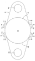
液面検出装置の底面図であり、
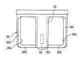
カバーの正面図であり、また
第2実施例のカバーの正面図。
以下、図面を参照しながら本開示を実施するための形態を、複数の形態を用いて説明する。各実施例で先行する実施例で説明している事項に対応している部分には同一の参照符を付すか、または先行の参照符号に一文字追加し、重複する説明を略する場合がある。また各実施例にて構成の一部を説明している場合、構成の他の部分は、先行して説明している実施例と同様とする。各実施例で具体的に説明している部分の組合せばかりではなく、特に組合せに支障が生じなければ、実施例同士を部分的に組合せることも可能である。
(第1実施例)
本開示の第1実施例に関して、図1~図3を用いて説明する。図1に示す液面検出装置Dは、車両の内燃機関に搭載され、潤滑油の液面レベルLVを検出するものである。この潤滑油は、車両に搭載された内燃機関に用いられるものであり、内燃機関を構成するシリンダブロックの下部に取り付けられたオイルパン11に貯留されている。オイルパン11は、金属により有底カップ状に形成され、車両において内燃機関のシリンダブロックに固定されている。オイルパン11は、内燃機関の摺動部分を潤滑するための潤滑油を貯留するために、シリンダブロックの底部開口を覆っている。内燃機関の回転時には、例えばストレーナを通じたオイルポンプによる吸い込みやコンロッドの油掻き板による掻揚げ等に起因して撹拌される潤滑油には、空気が気泡として混入する。
本開示の第1実施例に関して、図1~図3を用いて説明する。図1に示す液面検出装置Dは、車両の内燃機関に搭載され、潤滑油の液面レベルLVを検出するものである。この潤滑油は、車両に搭載された内燃機関に用いられるものであり、内燃機関を構成するシリンダブロックの下部に取り付けられたオイルパン11に貯留されている。オイルパン11は、金属により有底カップ状に形成され、車両において内燃機関のシリンダブロックに固定されている。オイルパン11は、内燃機関の摺動部分を潤滑するための潤滑油を貯留するために、シリンダブロックの底部開口を覆っている。内燃機関の回転時には、例えばストレーナを通じたオイルポンプによる吸い込みやコンロッドの油掻き板による掻揚げ等に起因して撹拌される潤滑油には、空気が気泡として混入する。
図1の上下方向を示す矢印は、車両に搭載された状態における液面検出装置Dの上下方向を示す。オイルパン11の内面には、水平方向に張り出した金属製の片持ち梁12が取り付けられている。液面検出装置Dは片持ち梁12にボルト13によって固定されている。
液面検出装置Dは、オイルパン11内における潤滑油の液面レベルLVが所定レベル以下となると、検出信号を出力する。例えば、車両の室内に設置された表示装置は、液面検出装置Dから検出信号が出力されている場合に、潤滑油の貯留量が不足している旨を警告表示する。
次に、液面検出装置Dの具体的な構成に関して説明する。液面検出装置Dは、図1に示すように、ボデー20、カバー30、フロート40および検出部50を備える。ボデー20、カバー30およびフロート40は耐油性に優れた樹脂材料によって形成されており、特にボデー20およびカバー30には熱可塑性の樹脂が用いられている。ボデー20は、ボルト穴20aが形成された板形状であり、ボルト穴20aに挿通されたボルト13により片持ち梁12に固定されている。ボデー20は片持ち梁12の下側に位置し、カバー30はボデー20の下側に位置する。
カバー30は、有底円筒形状であり、円筒形状の壁部301と、壁部301の下端を閉塞する底部302とを有する。したがって壁部301は、底部の外周に設けられ上下に延びるように設けられる。またカバー30は、図3に示すように、底部302から上方に延びる支持部70を有する。壁部301の上端はボデー20により閉塞されており、カバー30およびボデー20で囲まれたカバー30の内部にフロート40が収容されている。
支持部70は、フロート40を支持する。支持部70は、フロート40の上下の変位を許容し、カバー30の外部への変位を規制する。支持部70は、柱状であって、フロート40を挿通した状態で支持している。フロート40は、カバー30の内部において、上下方向に所定範囲で移動可能に配置されている。具体的には、フロート40は、下方は底部302に接触位置が下限位置であり、上方はボデー20に接触する位置が上限位置である。したがってフロート40は、底部302によって落下することが防止されている。フロート40は、潤滑油よりも比重の小さい部材であり、円環状に形成されている。フロート40は、支持部70の外側に同軸となるように配置されており、支持部70を案内されて、潤滑油の液面に浮遊することにより液面レベルLVに応じて上下に移動する。
壁部301には、大きな開口30aが形成されており、この開口30aを通じて、潤滑油がカバー30の内部へ流入または流出する。したがって、オイルパン11に貯留されている潤滑油の液面レベルLVが図1に示す位置、つまり収容室よりも上方に位置する場合には、収容室に潤滑油が充満し、フロート40は所定範囲の上限位置に位置する。オイルパン11に貯留されている潤滑油の液面レベルLVが底部302の位置よりも低下している場合には、潤滑油の液面レベルLVは底部302の位置よりも低下し、これに伴いフロート40の位置も低下する。以下の説明では、底部302の位置まで潤滑油が低下した状態におけるフロート40の位置を、下限位置と呼ぶ。
検出部50は、フロート40の上下方向の位置が下限位置以下であるか否かを検出する。検出部50は、非接触式の素子であり、例えば、フロート40に取り付けられた図示しない磁石により生じる磁界の強度を検出する。つまり、フロート40が下限位置以下にある場合に、検出される磁界強度が閾値を超えるように検出部50は配置されている。検出部50は、検出される磁界強度が閾値を超えた場合にオン信号を出力してもよいし、検出される磁界強度に応じたアナログ信号を出力してもよい。アナログ信号を出力する場合、図示しない回路部品により磁界強度が閾値を超えたか否かを判定し、閾値を超えたと判定された場合に回路部品がオン信号を出力してもよい。
このようにフロート40に取り付けられた磁石によって液面レベルLVの変化が磁界変化を引き起こし、さらに検出部50がこの磁界変化を電気信号に変換して出力することで、オイルパン11内の潤滑油の残量を検出することができる。
図1および図2に示すように、カバー30の壁部301には、壁部301の外周面から径方向へ突出する形状のカバー側台座31が形成されている。カバー側台座31の突出端面31aには、壁部301の径方向へ突出する形状のカバー側溶着部32が形成されている。カバー側溶着部32は、突出端面31aの中央から部分的に突出している。つまり、カバー側台座31とカバー側溶着部32とは図2に示す段差を有した形状に形成されている。カバー側台座31は、壁部301の複数箇所に形成されており、各々のカバー側台座31にカバー側溶着部32が形成されている。カバー側溶着部32およびカバー側台座31は、壁部301と一体に樹脂成形されたものである。
ボデー20にも同様に、ボデー20の外周面から突出する形状のボデー側台座21が形成されている。ボデー側台座21の突出端面には、ボデー側台座21の突出方向と同方向へさらに突出する形状のボデー側溶着部22が形成されている。ボデー側溶着部22は、突出端面の中央から部分的に突出している。つまり、ボデー側台座21とボデー側溶着部22とは、カバー30のカバー側溶着部32およびカバー側台座31と同様の段差を有した形状に形成されている。ボデー側台座21は、ボデー20の外周面の複数箇所に形成されており、各々のボデー側台座21にボデー側溶着部22が形成されている。ボデー側溶着部22およびボデー側台座21は、ボデー20と一体に樹脂成形されたものである。
そしてボデー20の下面20bおよびカバー30の上面30bが互いに面接触するようにボデー20およびカバー30は配置されている。この配置の状態において、ボデー側溶着部22とカバー側溶着部32も面接触しており、かつ、ボデー側溶着部22とカバー側溶着部32が溶着されている。つまり、ボデー側溶着部22およびカバー側溶着部32の表面には、熱溶融して一体となった状態で冷却固化された溶融固化部60が形成されている。図1で溶融固化部60に示す仮想線は、溶着前のボデー20とカバー30とを隔てる境界線である。このようにボデー側溶着部22とカバー側溶着部32とが溶着により結合されることで、カバー30はボデー20に固定される。
次に、カバー30の形状に関して、図3を用いて説明する。図3では、理解を容易にするためカバー側台座31とカバー側溶着部32とを除いた状態を示している。カバー30は、前述のように支持部70、壁部301および底部302を有する。壁部301は、支持部70の周囲に配置される。そして壁部301には、カバー30の内部と外部とを連通する開口30aが形成されている。開口30aの開口面積は、図1に示すように、開口30aを除いた壁部301の表面積よりも大きい。壁部301の表面積は、図1を見る側方から壁部301を見たときの表面積である。
開口30aは、上下方向に延び、周方向に間隔をあけて4つ形成されている。換言すると、周方向に隣接する開口30aの間には、壁部301が配置されている。したがって壁部301も4つ分割されており、底部302からみると十字に延びるように配置されている。周方向に見て、開口30aの寸法と壁部301の寸法とを比較すると、開口30aの寸法が大きい。
フロート40の浮遊による上限位置にフロート40が配置されている場合、フロート40の上面40aが開口30aと対向している。換言すると、フロート40が上限位置にある場合、側方から見て開口30aを介してフロート40の上面40aを視認することができる。また図1に示すように、フロート40の浮遊による下限位置にフロート40が配置されている場合、フロート40の下面40bが開口30aと対向している。換言すると、フロート40が下限位置にある場合、側方から見て開口30aを介してフロート40の下面40bを視認することができる。したがってフロート40は、開口30aを介して常に視認することができる。
以上説明したように本実施例の液面検出装置Dは、カバー30の壁部301に開口30aが形成されている。開口30aは、壁部301の表面積よりも大きい。このような大きい開口30aが形成されているので、気泡の逃げ道が大きく、気泡がカバー30の内部に留まることを抑制することができる。したがって気泡によってフロート40の位置が変化することを抑制することができ、検出部50によるフロート40の誤検出を抑制することができる。
換言すると、気泡の溜まりによるフロート40の誤作動を解決するために、カバー30に開口30aという大きな窓を設け、気泡の逃げ道を確保している。また片持ち梁12の形状によっては、片持ち梁12およびボデー20を介して、カバー30の内部に潤滑油が浸入することがある。フロート40の上から潤滑油が侵入して、フロート40に落下した潤滑油があたるとフロート40が下方に押し下げられ、検出部50が誤検出することがある。しかし本実施例では、前述のように大きな開口30aがあるので、フロート40に当たった潤滑油も開口30aから逃げやすい。したがってフロート40が変に落下した潤滑油で押し下げられることを抑制することができる。したがって片持ち梁12とボデー20とを密に接合する必要がないので、片持ち梁12の設計自由度が向上することができる。
また本実施例では、液面検出装置Dは、内燃機関において撹拌により気泡が混入するエンジンオイルの液面レベルLVを検出する。オイルパン11には、ストレーナが設けられ、ストレーナの吸引によって潤滑油が撹拌されるので、従来は気泡の流れを考慮してカバー30に貫通孔を形成している。しかし本実施例では、開口30aを大きく形成しているので、ストレーナの位置にかかわらず、カバー30の向きや位置を考慮する必要がない。したがって液面検出装置Dの配置位置の自由度が向上することができ、製品に応じて設計を変更する必要がないので、標準化が可能である。
また本実施例では、カバー30は樹脂材料からなるが、カバー30に大きな開口30aを形成しているので、カバー30の材料費を低減することができる。またカバー30は、樹脂材料からなるが、壁部301および底部302を有するので、フロート40を支持する強度を確保することができる。
さらに本実施例では、上限位置にフロート40がある場合には、フロート40の上面40aと対向する位置に開口30aがある。これによってカバー30およびボデー20を片持ち梁12に組み付けた後に、フロート40の作動高さを目視によって測定することが可能となる。これによってフロート40の位置による動作確認を容易となる。
(第2実施例)
次に、本開示の第2実施例に関して、図4を用いて説明する。本実施例では、開口30aの上下方向の大きさが前述の第1実施例と異なる点に特徴を有する。図4に示すように、開口30aはフロート40の下限位置においては、フロート40の下面40bと対向してない。換言すると、フロート40が下限位置にある場合には、フロート40の下面40bは開口30aを介して視認することができない。
次に、本開示の第2実施例に関して、図4を用いて説明する。本実施例では、開口30aの上下方向の大きさが前述の第1実施例と異なる点に特徴を有する。図4に示すように、開口30aはフロート40の下限位置においては、フロート40の下面40bと対向してない。換言すると、フロート40が下限位置にある場合には、フロート40の下面40bは開口30aを介して視認することができない。
したがって開口30aの上下方向の寸法は、前述の第1実施例の開口30aよりも小さい。壁部301は、底部302の全周から上下方向に延び、その後、開口30aによって十字に分岐している。したがって底部302と壁部301の下方によって、お椀状に形成されている。したがって底部302と壁部301とは、潤滑油を貯留可能に構成されている。
検出部50は、開口30aが周方向に位置している部分に配置される。検出部50は、フロート40が下限位置にあるときに信号を出力するように構成される。
このような構成であっても、開口30aは充分に大きいので、前述の第1実施例のように気泡をカバー30の外に逃がすことができる。また底部302と壁部301とによってお椀型を構成することによって、カバー30の強度を向上することができる。
(その他の実施例)
前述の実施例の構造は、あくまで例示であって、本開示の範囲はこれらの記載の範囲に限定されるものではない。
前述の実施例の構造は、あくまで例示であって、本開示の範囲はこれらの記載の範囲に限定されるものではない。
前述の第1実施例では、開口30aの数は4つであるが、4つに限るものではなく、カバー30の強度や潤滑油および気泡の抜けを考慮したうえで、変更は可能である。また開口30aは、周方向に分割されているが、上下方向に複数に分割されている構成であってもよい。
前述の第1実施例では、車両用の液面検出装置Dであるが、車両用に限らず、各種民生用機器、各種輸送機器が備える燃料タンク内に設けられる液面検出装置に、本開示は適用可能である。したがってオイルパン11以外の容器の内部に貯留されるオイル以外の液体につき、液面レベルLVを検出する各種液面検出装置にも、本開示を適用してもよい。
前述の第1実施例では、液面レベルLVに応じたオンオフによりオン信号又はオフ信号を出力する検出部50が用いられているが、他の検出部として、たとえば液面レベルLVに応じて信号電圧が連続変化するセンサ等を採用してもよい。
上述した液面検出装置は、フロート40と、カバー30と、検出部50と、を含む。フロート40は、容器の内部において液体に浮遊することにより液面レベルLVに応じて上下に移動する。カバー30は、容器の内部に配置され、フロートを内部に収容する。検出部50は、フロートの位置を検出する。カバーは、支持部70と、壁部301と、を有する。支持部70は、フロートの上下の変位を許容し、カバーの外部への変位を規制する。壁部301は、支持部の周囲に配置される。壁部には、カバーの内部と外部とを連通する開口30aが形成されており、開口の開口面積は、開口を除いた壁部の表面積よりも大きい。
このような本開示に従えば、カバーには、壁部の表面積よりも大きい開口が形成されている。このような大きい開口が形成されているので、気泡の逃げ道が大きく、気泡がカバーの内部に留まることを抑制することができる。したがって気泡によってフロートの位置が変化することを抑制することができ、検出部によるフロートの誤検出を抑制することができる。
本開示は、実施例に準拠して記述されたが、本開示は当該実施例や構造に限定されるものではないと理解される。本開示は、様々な変形例や均等範囲内の変形をも包含する。加えて、様々な組み合わせや形態、さらには、それらに一要素のみ、それ以上、あるいはそれ以下、を含む他の組み合わせや形態をも、本開示の範疇や思想範囲に入るものである。
Claims (5)
- 容器(11)の内部に貯留された液体の液面レベル(LV)を検出する液面検出装置であって、
前記容器(11)の内部において前記液体に浮遊することにより前記液面レベル(LV)に応じて上下に移動するフロート(40)と、
前記容器(11)の内部に配置され、前記フロート(40)を内部に収容するカバー(30)と、
前記フロート(40)の位置を検出する検出部(50)と、を含み、
前記カバー(30)は、
前記フロート(40)の上下の変位を許容し、前記カバー(30)の外部への変位を規制する支持部(70)と、
前記支持部(70)の周囲に配置される壁部(301)と、を有し、
前記壁部(301)には、前記カバー(30)の内部と外部とを連通する開口(30a)が形成されており、
前記開口(30a)の開口面積は、前記開口(30a)を除いた前記壁部(301)の表面積よりも大きい液面検出装置。 - 前記フロート(40)の浮遊による上限位置に前記フロート(40)が配置されている場合、前記フロート(40)の上面が前記開口(30a)と対向している請求項1に記載の液面検出装置。
- 前記カバー(30)は、底部を有し、
前記壁部(301)は、前記底部の外周に設けられ上下に延び、
前記底部と前記壁部(301)とは、前記液体を貯留可能に構成されている請求項1または2に記載の液面検出装置。 - 前記カバー(30)は、樹脂材料によって形成されている請求項1~3のいずれか1つに記載の液面検出装置。
- 前記容器(11)は、内燃機関において撹拌により気泡が混入する潤滑油を、前記液体として貯留するオイルパンである請求項1~4のいずれか1つに記載の液面検出装置。
Priority Applications (3)
| Application Number | Priority Date | Filing Date | Title |
|---|---|---|---|
| US16/074,786 US10753782B2 (en) | 2016-02-05 | 2016-10-21 | Liquid-surface detection device |
| DE112016006363.6T DE112016006363T5 (de) | 2016-02-05 | 2016-10-21 | Flüssigkeitsoberflächen-Erfassungsvorrichtung |
| CN201680075278.2A CN108431559A (zh) | 2016-02-05 | 2016-10-21 | 液面检测装置 |
Applications Claiming Priority (2)
| Application Number | Priority Date | Filing Date | Title |
|---|---|---|---|
| JP2016-020865 | 2016-02-05 | ||
| JP2016020865A JP6384497B2 (ja) | 2016-02-05 | 2016-02-05 | 液面検出装置 |
Publications (1)
| Publication Number | Publication Date |
|---|---|
| WO2017134867A1 true WO2017134867A1 (ja) | 2017-08-10 |
Family
ID=59499631
Family Applications (1)
| Application Number | Title | Priority Date | Filing Date |
|---|---|---|---|
| PCT/JP2016/081201 Ceased WO2017134867A1 (ja) | 2016-02-05 | 2016-10-21 | 液面検出装置 |
Country Status (5)
| Country | Link |
|---|---|
| US (1) | US10753782B2 (ja) |
| JP (1) | JP6384497B2 (ja) |
| CN (1) | CN108431559A (ja) |
| DE (1) | DE112016006363T5 (ja) |
| WO (1) | WO2017134867A1 (ja) |
Families Citing this family (1)
| Publication number | Priority date | Publication date | Assignee | Title |
|---|---|---|---|---|
| WO2021087725A1 (zh) * | 2019-11-05 | 2021-05-14 | 深圳市大疆创新科技有限公司 | 一种插拔检测方法、装置及飞行器、计算机存储介质 |
Citations (4)
| Publication number | Priority date | Publication date | Assignee | Title |
|---|---|---|---|---|
| JPS5359321U (ja) * | 1976-10-22 | 1978-05-20 | ||
| JP2006284258A (ja) * | 2005-03-31 | 2006-10-19 | Citizen Miyota Co Ltd | 液面検出センサ及び液面検出センサを有する液体容器 |
| JP2014126399A (ja) * | 2012-12-25 | 2014-07-07 | Toyota Motor Corp | オイルレベルセンサ |
| JP2014235158A (ja) * | 2013-06-05 | 2014-12-15 | 株式会社デンソー | 液面検出装置 |
Family Cites Families (9)
| Publication number | Priority date | Publication date | Assignee | Title |
|---|---|---|---|---|
| JPS54161567U (ja) * | 1978-05-01 | 1979-11-12 | ||
| US4497205A (en) * | 1982-12-17 | 1985-02-05 | Gulf & Western Manufacturing Company | Method and apparatus for automatically sensing the level of a liquid in a reservoir |
| US5161518A (en) * | 1991-07-31 | 1992-11-10 | Cleveland Range, Incorporated | Float assembly for steam cooking device |
| JP2002062180A (ja) * | 2000-08-22 | 2002-02-28 | Denso Corp | 車両用液面検出器 |
| US8127597B2 (en) * | 2008-01-28 | 2012-03-06 | GM Global Technology Operations LLC | Oil condition sensing methods and systems |
| US9175585B2 (en) * | 2013-05-24 | 2015-11-03 | GM Global Technology Operations LLC | Fluid level detection device with stabilizer |
| JP6156040B2 (ja) | 2013-10-07 | 2017-07-05 | 株式会社デンソー | 液面検出装置 |
| JP2016020865A (ja) | 2014-07-15 | 2016-02-04 | 古河電気工業株式会社 | 光ファイバを用いた応力分布測定方法および応力分布測定装置 |
| JP6916182B2 (ja) * | 2015-11-30 | 2021-08-11 | ボーンズ・インコーポレーテッドBourns,Incorporated | フロートを介しての流体の特性の検出 |
-
2016
- 2016-02-05 JP JP2016020865A patent/JP6384497B2/ja active Active
- 2016-10-21 WO PCT/JP2016/081201 patent/WO2017134867A1/ja not_active Ceased
- 2016-10-21 US US16/074,786 patent/US10753782B2/en active Active
- 2016-10-21 DE DE112016006363.6T patent/DE112016006363T5/de active Pending
- 2016-10-21 CN CN201680075278.2A patent/CN108431559A/zh active Pending
Patent Citations (4)
| Publication number | Priority date | Publication date | Assignee | Title |
|---|---|---|---|---|
| JPS5359321U (ja) * | 1976-10-22 | 1978-05-20 | ||
| JP2006284258A (ja) * | 2005-03-31 | 2006-10-19 | Citizen Miyota Co Ltd | 液面検出センサ及び液面検出センサを有する液体容器 |
| JP2014126399A (ja) * | 2012-12-25 | 2014-07-07 | Toyota Motor Corp | オイルレベルセンサ |
| JP2014235158A (ja) * | 2013-06-05 | 2014-12-15 | 株式会社デンソー | 液面検出装置 |
Also Published As
| Publication number | Publication date |
|---|---|
| JP2017138267A (ja) | 2017-08-10 |
| JP6384497B2 (ja) | 2018-09-05 |
| DE112016006363T5 (de) | 2018-10-11 |
| CN108431559A (zh) | 2018-08-21 |
| US20190041252A1 (en) | 2019-02-07 |
| US10753782B2 (en) | 2020-08-25 |
Similar Documents
| Publication | Publication Date | Title |
|---|---|---|
| US9417113B2 (en) | Fill level sensor for detecting the fill level of a liquid in a container | |
| US9952086B2 (en) | Magnetic float liquid level detector with vertically reversible attachment | |
| US10852174B2 (en) | Device for sensing the pressure of a medium | |
| JP6384497B2 (ja) | 液面検出装置 | |
| CN103234601A (zh) | 盛装液体的容器 | |
| CN115280115A (zh) | 可浸没的自持物位测量系统 | |
| JP2015059742A (ja) | 車載用液体タンク | |
| EP1987560A2 (en) | Hydrometer/fluid level sensor | |
| CN104179548A (zh) | 具有稳定器的液体液位检测装置 | |
| CN118974385A (zh) | 罐 | |
| US10295395B2 (en) | Fuel tank | |
| CN212228165U (zh) | 一种液面检测装置及机动车 | |
| US10197431B2 (en) | Device for measuring the filling level of a liquid | |
| JP2020085224A (ja) | ブリーザ装置 | |
| JP2018130650A (ja) | フィルタ装置 | |
| KR200359536Y1 (ko) | 유수분리 장치 | |
| KR102611557B1 (ko) | 충전 레벨 지시기를 구비한 탱크 및 상기 탱크를 포함한 콤팩트 어셈블리 | |
| JP2015219063A (ja) | 液面検出装置 | |
| CN2828763Y (zh) | 车辆用静电容量式传感器 | |
| CN115824351B (zh) | 液位探针组件、液体箱及包括液体箱的设备 | |
| CN219573210U (zh) | 一种水位指示装置和水罐车 | |
| US20180087950A1 (en) | Device for measuring a fill level of a liquid in a container with an ultrasonic sensor | |
| JP3213565U (ja) | 液量検出装置 | |
| JP3113064U (ja) | タンク内油量表示棒 | |
| JP4506457B2 (ja) | 樹脂製リザーバ |
Legal Events
| Date | Code | Title | Description |
|---|---|---|---|
| 121 | Ep: the epo has been informed by wipo that ep was designated in this application |
Ref document number: 16889350 Country of ref document: EP Kind code of ref document: A1 |
|
| WWE | Wipo information: entry into national phase |
Ref document number: 112016006363 Country of ref document: DE |
|
| 122 | Ep: pct application non-entry in european phase |
Ref document number: 16889350 Country of ref document: EP Kind code of ref document: A1 |