WO2017130951A1 - ボールねじ - Google Patents
ボールねじ Download PDFInfo
- Publication number
- WO2017130951A1 WO2017130951A1 PCT/JP2017/002312 JP2017002312W WO2017130951A1 WO 2017130951 A1 WO2017130951 A1 WO 2017130951A1 JP 2017002312 W JP2017002312 W JP 2017002312W WO 2017130951 A1 WO2017130951 A1 WO 2017130951A1
- Authority
- WO
- WIPO (PCT)
- Prior art keywords
- nut
- ball screw
- screw
- curved surface
- groove
- Prior art date
- Legal status (The legal status is an assumption and is not a legal conclusion. Google has not performed a legal analysis and makes no representation as to the accuracy of the status listed.)
- Ceased
Links
Images


Classifications
-
- F—MECHANICAL ENGINEERING; LIGHTING; HEATING; WEAPONS; BLASTING
- F16—ENGINEERING ELEMENTS AND UNITS; GENERAL MEASURES FOR PRODUCING AND MAINTAINING EFFECTIVE FUNCTIONING OF MACHINES OR INSTALLATIONS; THERMAL INSULATION IN GENERAL
- F16H—GEARING
- F16H25/00—Gearings comprising primarily only cams, cam-followers and screw-and-nut mechanisms
- F16H25/18—Gearings comprising primarily only cams, cam-followers and screw-and-nut mechanisms for conveying or interconverting oscillating or reciprocating motions
- F16H25/20—Screw mechanisms
- F16H25/22—Screw mechanisms with balls, rollers, or similar members between the co-operating parts; Elements essential to the use of such members
Definitions
- the present invention relates to a ball screw. Specifically, it relates to a circulating ball screw.
- the ball screw is composed of a screw shaft having a thread groove formed on an outer peripheral surface and a nut supported via a plurality of balls as rolling elements.
- the ball screw is configured as a motion conversion mechanism in which one of the screw shaft or the nut rotates and the other linearly moves as a linear motion member.
- a non-circulating ball screw in which the ball does not circulate is known.
- the non-circulating ball screw has an annular rolling groove formed on the inner peripheral surface of a nut and holds the ball by a cage. For example, as described in Patent Document 1.
- two spiral rolling grooves are formed on the outer peripheral surface of the screw shaft, and two rows of annular rolling grooves are formed on the inner peripheral surface of the nut.
- the annular rolling groove is formed on both sides of the annular convex portion formed in the central portion of the inner peripheral surface of the nut.
- two balls are disposed in each annular rolling groove, and are in angular contact with the spiral rolling groove of the screw shaft and the annular rolling groove of the nut. The two balls are rotatably held with respect to the screw shaft and the nut in a state where the positional relationship is maintained in the annular rolling groove by the cage.
- the ball screw rolls on the spiral rolling groove of the screw shaft while the ball rolls on the annular rolling groove of the nut. That is, the ball screw can convert the rotational motion into a linear motion only by forming two rows of annular rolling grooves on the inner peripheral surface of the nut in order to reduce production costs.
- the number of balls that can be arranged in the annular rolling groove of the nut and the position thereof are determined by the number of spiral rolling grooves on the screw shaft. For this reason, it is disadvantageous in that the allowable load capacity is limited as compared with the circulation type ball screw.
- the present invention has been made in view of the above circumstances, and an object thereof is to provide a ball screw capable of increasing the allowable load capacity while suppressing the production cost.
- the ball screw of the present invention is a circulation type ball screw in which a screw shaft is inserted into a nut and a plurality of balls are arranged in a rolling path constituted by the screw groove of the screw shaft and the screw groove of the nut.
- the nut thread groove is provided substantially on one axial side and the other side of the inner peripheral surface so as to increase or decrease the diameter of both ends in the axial direction of the inner peripheral surface of the nut.
- the end portions shifted in the axial direction in each of the spiral step shapes are connected with a smooth curved surface to form an annular shape, and the end portions of the spiral step shape
- the smooth curved surface connecting the two is formed with a concave portion that extends radially outward of the nut, and the stepped surface of the spiral step shape is formed on a curved surface facing the screw groove of the screw shaft. It is.
- annular guide plate is provided on the diameter-enlarged portion of the inner peripheral surface of the nut, and the spiral stepped ends of the guide plates are connected to each other.
- the portion facing the smooth curved surface is a smooth curved surface along the spiral step shape so that the ball rolls along a smooth curved surface connecting the ends of the spiral step shape. It is preferable to be formed.
- a part of the annular guide plate is opened and formed so as to be able to reduce the diameter in the radial direction.
- the annular guide plate is engaged with a slit formed on the inner peripheral surface of the nut.
- the annular guide plate is made of a high steel wire rod for a spring.
- the ball screw is constituted by a nut having a thread groove having a spiral step shape that can be formed by a mold.
- the ball screw is formed in an annular shape with a smooth curved surface in a step shape that is a thread groove so that the ball disposed in the thread groove circulates in the thread groove of the nut. That is, the ball screw is configured as a circulation type ball screw in which a plurality of balls are continuously arranged in a thread groove of a nut that can be formed of a mold. Thereby, the allowable load capacity can be increased while suppressing the production cost.
- the nut thread is formed in an annular shape that allows the ball to circulate in a state where one side is released. That is, the ball screw is composed of a nut having an annular thread groove that can be formed of a mold without an undercut. Thereby, the allowable load capacity can be increased while suppressing the production cost.
- the guide plate is easily incorporated into the nut, and a screw groove is formed through which the ball can circulate.
- the allowable load capacity can be increased while suppressing the production cost.
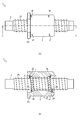
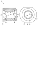
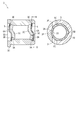
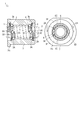
- the perspective view which shows the whole structure in one Embodiment of a ball screw (A) The top view which shows the whole structure in one Embodiment of a ball screw. (B) The A arrow directional cross-sectional view in FIG. 2 (A). The axial direction sectional view and side view of a nut in one embodiment of a ball screw. The axial direction sectional view and arrow A sectional view in the state where the guide board was provided in the nut in one embodiment of a ball screw. The axial direction sectional view and side view showing the mode of the ball which rolls the nut side thread groove of the nut in one embodiment of a ball screw.
- step-shaped nut-side thread grooves 3 ⁇ / b> A are formed on the inner peripheral surface of the nut 3 of the ball screw 1, with the end portions on both sides in the axial direction being enlarged.
- the ball screw 1 converts rotational motion into linear motion and outputs it.
- the ball screw 1 includes a screw shaft 2, a nut 3, a plurality of balls 4, and the like.
- the screw shaft 2 is made of medium carbon steel such as S55C or case-hardened steel such as SCM415 or SCM420, and is hardened by about 55 to 62 HRC by induction hardening or vacuum carburization hardening.
- the screw shaft 2 has a plurality of shaft-side thread grooves 2A for rolling the ball 4 on the outer peripheral surface thereof.
- the cross-sectional shape of the shaft side thread groove 2A may be a circular arc shape or a gothic arc shape.
- the screw shaft 2 is formed in a Gothic arc shape that allows a large contact angle with the ball 4 and a small axial clearance. Thereby, the ball screw 1 has high rigidity with respect to the axial load of the screw shaft 2 and can suppress the occurrence of vibration.
- the nut 3 is formed in a hollow cylindrical shape into which the screw shaft 2 can be inserted.
- the nut 3 is made of a sintered alloy prepared by adjusting a metal powder into a plastic shape and molded by an injection molding machine.
- the nut 3 is formed by MIM (Metal Injection Molding) in which a kneaded product of a metal powder and a binder made of plastic and wax is pushed into a mold in a heated and melted state.
- MIM Metal Injection Molding
- C carbon
- Ni nickel
- Cr chromium
- Cu copper
- SCM415 consisting of 0.04 wt%, Mn (manganese) 0.76 wt%, Mo (molybdenum) 0.19 wt%, Si (silicon) 0.20 wt%, and the rest Fe (iron) or the like.
- the material of the nut 3 includes 3.0 to 10.0 wt% of Ni and is excellent in workability and corrosion resistance (FEN8 of Japanese Powder Metallurgy Industry Standard), or C is 0.07 wt%. %, Cr is 17 wt%, Ni is 4 wt%, Cu is 4 wt%, and the remainder is precipitation hardened stainless steel SUS630 made of Fe or the like. This SUS630 can appropriately increase the surface hardness in the range of 20 to 33 HRC by solution heat treatment, and can ensure toughness and high hardness.
- the nut 3 is formed by MIM, but is not limited to this, and may be formed by forging.
- step-shaped nut-side thread grooves 3A in which the end portions on both sides in the axial direction are enlarged.
- a rolling surface 3 ⁇ / b> B is formed of a curved surface in which the stepped surface connecting the reduced diameter portion of the central portion and the enlarged diameter portion of the end portion gradually increases in diameter toward the respective end portions of the nut 3. Is formed.
- the nut-side thread groove 3A formed in each step shape is formed in a substantially clockwise clockwise spiral.
- each step shape is connected by a smooth curved surface 3C at the end shifted in the axial direction by the amount of the spiral lead.
- each step shape is connected by a smooth curved surface 3 ⁇ / b> C to the stepped surface moved to the position adjacent to the original end portion by being wound substantially spirally.
- each step-shaped nut-side screw groove 3A is formed in an annular shape in which the rolling surface 3B which is a step surface is continuous without interruption.
- the smooth curved surface 3C connecting the rolling surface 3B which is a step surface shifted in the axial direction by the spiral, is a radial direction toward the center in the circumferential direction.
- a recess 3D deeper than the groove depth of the shaft-side screw groove 2A is formed outward.
- a nut-side screw groove 3A having a circular spiral step shape connected by a smooth curved surface 3C is formed on the inner peripheral surface of the nut 3 configured in this manner.
- the nut-side thread groove 3A is composed only of a rolling surface 3B having a curved surface that gradually increases in diameter from the reduced diameter portion of the central portion of the nut 3 toward each end portion.
- the nut-side thread groove 3A is configured as an undercut-free groove whose side wall is only on one side.
- the nut-side thread groove 3 ⁇ / b> A is formed with the same lead and pitch as the shaft-side thread groove 2 ⁇ / b> A of the screw shaft 2.
- a stepped shape in which the diameter of both ends in the axial direction is increased so as to follow the nut-side screw groove 3A is formed in the diameter-expanded portion of the nut 3 respectively.
- the guide plate positioning portion 3E is formed in a substantially clockwise clockwise spiral on the opening side of the nut side screw groove 3A.
- the slit 3F for fixing the guide plate 5 is formed in the diameter-expanded part of the nut 3 so that the guide plate positioning part 3E may be followed.
- an annular guide plate 5 (light ink portion in FIGS. 1, 2, and 4) is provided on the inner peripheral surface of the nut 3.
- the guide plate 5 holds the ball 4 as a rolling element in the nut-side thread groove 3A.
- the guide plate 5 is formed in a substantially clockwise spiral shape.
- the guide plate 5 is made of a high steel wire rod for spring, or a steel material that has been subjected to hardening treatment of about 55 to 62 HRC by induction hardening or vacuum carburizing and hardening.
- the guide plate 5 is connected by a smooth curved surface 5A at a portion displaced in the axial direction by the amount of the spiral lead.
- the smooth curved surface 5A of the guide plate 5 has a protruding portion 5B formed radially outward as it goes toward the center in the circumferential direction.
- the smooth curved surface 5A is formed into a curved surface substantially the same as the smooth curved surface 3C of the nut-side thread groove 3A of the nut 3.
- the guide plate 5 is formed in a substantially C shape by opening a portion facing the portion formed on the smooth curved surface 5A. Thereby, the guide plate 5 is configured to be capable of reducing the diameter in the radial direction by bringing both ends of the opening close to each other.
- Engaging portions 5 ⁇ / b> C protruding in the radial direction are formed at both ends of the opening of the guide plate 5.
- the guide plate 5 is fixed to the inner peripheral surface of the nut 3 by being inserted into the slit 3F formed in the nut 3 while being positioned by the guide plate positioning portion 3E of the nut 3.
- the guide plate 5 is fixed at a position where the ball 4 can pass between the side wall (step surface) of the nut-side screw groove 3A.
- the smooth curved surface 5 ⁇ / b> A of the guide plate 5 is arranged to face the smooth curved surface 3 ⁇ / b> C of the nut 3.
- a flange portion 3 ⁇ / b> G that is a stepped portion having a partially enlarged outer diameter is formed.
- the screw shaft 2 is inserted into the nut 3 so that the shaft-side screw groove 2 ⁇ / b> A and the nut-side screw groove 3 ⁇ / b> A face each other.
- a plurality of balls 4 that are rolling elements are housed in a space formed by the shaft-side screw groove 2A and the nut-side screw groove 3A so as to freely roll.
- the nut-side thread groove 3A is formed such that a smooth curved surface 3C straddles the side wall of the shaft-side thread groove 2A. As shown in FIG.
- the balls 4 accommodated so as to roll between the nut-side thread groove 3A of the nut 3 and the shaft-side thread groove 2A of the screw shaft 2 are arranged in a double row outward with a contact angle ⁇ . It is configured to make an angular contact.
- the shaft side thread groove 2A and the nut side thread groove 3A constitute a rolling path on which the plurality of balls 4 roll.
- the nut 3 supports the screw shaft 2 through a plurality of balls 4 so as to be rotatable around the axis of the nut 3.
- the ball screw 1 transmits a rotational force to the screw shaft 2 via a plurality of balls 4 accommodated in the rolling path.
- the rotational motion of the nut 3 is converted into linear motion in the axial direction of the screw shaft 2 by the inclination of the shaft-side screw groove 2A.
- the rotational force is transmitted to the nut 3 via the plurality of balls 4 accommodated in the rolling path.
- the rotational motion of the screw shaft 2 is converted into the linear motion of the nut 3 in the axial direction by the inclination of the shaft-side screw groove 2A.
- the shaft side thread groove 2A and the nut side thread groove 3A of the screw shaft 2 are substantially wound, but the present invention is not limited to this.
- the shaft-side thread groove 2A formed in the screw shaft 2 is a right-hand thread, but is not limited thereto.
- the nut-side thread groove 3A of the nut 3 is formed with a smooth curved surface 3C so as to straddle the side wall of the shaft-side thread groove 2A of the screw shaft 2, and the smooth curved surface 3C has a shaft.
- a recess 3D that is deeper than the groove depth of the side screw groove 2A is formed. Therefore, as shown in FIGS. 5 and 6, the ball 4 that has reached the smooth curved surface 3C of the nut-side thread groove 3A gradually moves to the side wall of the shaft-side thread groove 2A by the smooth curved surface 3C of the nut-side thread groove 3A. Sent to.
- the ball 4 is pushed up toward the tip of the shaft side thread groove 2A along the side wall of the shaft side thread groove 2A. At this time, since the ball 4 is held by the guide plate 5 formed along the smooth curved surface 3C, it does not fall off the rolling path. That is, even if the nut-side thread groove 3A is formed in a groove shape without an undercut on only one side, the ball 4 that attempts to cross the side wall of the shaft-side thread groove 2A can be stably held. The ball 4 moves over the side wall of the shaft-side screw groove 2A to the adjacent shaft-side screw groove 2A by the smooth curved surface 3C of the nut-side screw groove 3A, and the original screw groove position of the annular nut-side screw groove 3A. Return to.
- the ball 4 in the rolling path moves to the adjacent shaft side thread groove 2A and circulates in the rolling path by making a round of the nut side thread groove 3A.
- the ball screw 1 can arrange
- a ball screw 6 including a nut 7 having a different shape of the nut 3 may be used as another embodiment of the ball screw 1.
- step-shaped nut-side thread grooves 7A having diameters reduced at both ends in the axial direction are formed on the inner peripheral surface of the nut 7 of the ball screw 6, respectively.
- the ball screw 1 which concerns on all the following embodiments is replaced with the ball screw 1 in the ball screw 1 shown in FIGS. 1-6, and the name, figure number, and symbol used in the description are used. In the following embodiments, the same points as those of the already described embodiments will be omitted, and different portions will be mainly described.
- the ball screw 6 converts a rotational motion into a linear motion and outputs it.
- the ball screw 6 includes a screw shaft 2, a nut 7, a plurality of balls 4, and the like.
- step-shaped nut-side screw grooves 7 ⁇ / b> A each having a reduced diameter at both ends in the axial direction as nut-side screw grooves 7 ⁇ / b> A.
- a stepped surface connecting the reduced diameter portion of the portion and the enlarged diameter portion of the central portion is formed on the rolling surface 7B formed of a curved surface that gradually increases in diameter toward the central portion of the nut 7.
- the nut 7 is divided into two at a substantially central portion of the enlarged diameter portion, and is connected via a press-fit pin 8.
- the connecting method of the nut 7 is not limited to the press-fit pin 8 and may be screw fastening or the like.
- the nut-side thread groove 7A formed in each step shape is formed in a substantially clockwise clockwise spiral.
- Each step-shaped nut-side thread groove 7A is connected with a smooth curved surface (not shown) at the end shifted in the axial direction by the amount of the spiral lead.
- a step-shaped nut-side screw groove 7A processed into a spiral of approximately one turn in a state where the nut 7 is divided is formed in a continuous annular shape without interruption. Is formed.
- the nut-side thread groove 7A is configured as an undercut-free groove having a side wall only on one side.
- a stepped shape is formed by further expanding the diameter of the central enlarged portion along the nut-side screw groove 7A. Yes.
- the inner peripheral surface of the nut 7 is provided with a substantially one-turn clockwise spiral guide plate 5.
- the guide plate 5 holds the ball 4 as a rolling element in the nut side screw groove 7A.
- the guide plate 5 is configured to be able to reduce the diameter to an outer diameter smaller than the inner diameter of the reduced diameter portion of the nut 7.
- the guide plate 5 is fixed to the guide plate positioning portion 7D of the nut 7 by a slit (not shown) formed on the inner peripheral surface of the nut 7.
- the ball screws 1 and 6 can be formed into a substantially one-annular spiral spiral nut-side screw groove 3A consisting of only the shaft-side screw groove 2A of the screw shaft 2 and the side wall on one side of the nuts 3 and 7. , 7A, a plurality of balls 4 are arranged on the rolling path. That is, the ball screws 1 and 6 have nut-side thread grooves 3A and 7A without an undercut that can be formed from a mold, are formed in an annular spiral shape, and a plurality of balls 4 are continuously arranged to be circulated. . Thereby, the ball screws 1 and 6 can increase the allowable load capacity while suppressing the production cost.
- the ball screws 1 and 6 are easily provided with a guide plate 5 for preventing the ball 4 from dropping off. Thereby, the allowable load capacity can be increased while suppressing the production cost.
- the ball screws 1 and 6 which are one embodiment of the ball screw are assumed to be formed with the nut-like screw grooves 3A and 7A having substantially one turn on the nuts 3 and 7 on both sides in the axial direction.
- the above-described embodiment is merely a representative form, and various modifications can be made without departing from the scope of the embodiment. It goes without saying that the present invention can be embodied in various forms, and the scope of the present invention is indicated by the description of the scope of claims, and the equivalent meanings of the scope of claims, and all the scopes within the scope of the claims. Includes changes.
- the present invention can be used for a ball screw.
Landscapes
- Engineering & Computer Science (AREA)
- General Engineering & Computer Science (AREA)
- Mechanical Engineering (AREA)
- Transmission Devices (AREA)
Abstract
ボールねじの生産コストを抑制しつつ許容負荷容量を増大することを課題とする。ねじ軸(2)がナット(3)に挿入され、軸側ねじ溝(2A)とナット側ねじ溝(3A)とから構成される転動路に複数のボール(4)が配置される循環型のボールねじ(1)であって、ナット側ねじ溝(3A)は、ナット(3)の内周面の軸方向両側の端部を拡径または縮径するように内周面の軸方向一側と他側とにそれぞれ設けられる略一巻きの螺旋状の段差形状からなり、それぞれの前記螺旋状の段差形状において軸方向にずれた端部同士が滑らかな曲面(3C)で接続されて円環状に形成され、前記螺旋状の段差形状の端部同士を接続している滑らかな曲面には、ナット(3)の径方向外側に向かう凹部3Dが形成され、前記螺旋状の段差形状の段差面は、軸側ねじ溝(2A)に対向する曲面に形成される。
Description
本発明はボールねじに関する。詳しくは循環型のボールねじに関する。
従来、一般産業用の電動機、自動車のトランスミッションやパーキングブレーキ等の電動アクチュエータにおいて、電動モータの出力軸の回転運動を高効率で直線運動に変換して出力するためにボールねじが用いられている。ボールねじは、外周面にねじ溝が形成されたねじ軸と転動体である複数のボールを介して支持されるナットとから構成されている。これにより、ボールねじは、ねじ軸またはナットのうち一方を回転運動させることで他方が直動部材として直線運動する運動変換機構として構成されている。このように構成されるボールねじにおいて、ボールが循環しない非循環型のボールねじが知られている。非循環型のボールねじは、ナットの内周面に環状の転動溝が形成され、保持器によってボールを保持しているものである。例えば、特許文献1に記載の如くである。
特許文献1に記載のボールねじは、ねじ軸の外周面に二条の螺旋状の転動溝(ねじ溝)が形成され、ナットの内周面に二列の環状の転動溝が形成されている。環状の転動溝は、ナットの内周面の中央部に形成される環状凸部の両側に形成されている。ボールねじは、それぞれの環状の転動溝に2個のボールが配置され、ねじ軸の螺旋状の転動溝とナットの環状の転動溝とにアンギュラコンタクトしている。二個のボールは、保持器によって環状の転動溝内の互いの位置関係を維持した状態でねじ軸とナットとに対して回転自在に保持されている。このように構成することで、ボールねじは、ボールがナットの環状の転動溝を転動しつつ、ねじ軸の螺旋状の転動溝を転動する。つまり、ボールねじは、生産コストを抑制するためにナットの内周面に二列の環状の転動溝を形成するだけで回転運動を直線運動に変換することができる。しかし、特許文献1に記載の技術は、ナットの環状の転動溝に配置できるボールの数やその位置がねじ軸の螺旋状の転動溝の条数によって決まる。このため、循環型のボールねじに比べて許容負荷容量が制限される点で不利であった。
本発明は以上の如き状況に鑑みてなされたものであり、生産コストを抑制しつつ許容負荷容量を増大することができるボールねじの提供を目的とする。
本発明のボールねじは、ねじ軸がナットに挿入され、前記ねじ軸のねじ溝と前記ナットのねじ溝とから構成される転動路に複数のボールが配置される循環型のボールねじであって、前記ナットのねじ溝は、前記ナットの内周面の軸方向両側の端部を拡径または縮径するように内周面の軸方向一側と他側とにそれぞれ設けられる略一巻きの螺旋状の段差形状からなり、それぞれの前記螺旋状の段差形状において軸方向にずれた端部同士が滑らかな曲面で接続されて円環状に形成され、前記螺旋状の段差形状の端部同士を接続している滑らかな曲面には、前記ナットの径方向外側に向かう凹部が形成され、前記螺旋状の段差形状の段差面は、前記ねじ軸のねじ溝に対向する曲面に形成されるものである。
本発明のボールねじにおいては、前記ナットの内周面の拡径部分には、円環状の案内板が設けられ、前記案内板のうち前記螺旋状の段差形状の端部同士を接続している滑らかな曲面に対向する部分は、前記ボールが前記螺旋状の段差形状の端部同士を接続している滑らかな曲面に沿って転動するように、前記螺旋状の段差形状に沿う滑らかな曲面に形成されることが好ましい。
本発明のボールねじにおいては、前記円環状の案内板の一部は、開口されて径方向に縮径可能に形成されることが好ましい。
本発明のボールねじにおいては、前記円環状の案内板は、前記ナットの内周面に形成されているスリットに係合されることが好ましい。
本発明のボールねじにおいては、前記円環状の案内板がばね用高鋼線材から構成される
ことが好ましい。
ことが好ましい。
本発明のボールねじによれば、型物で形成可能な略一巻の螺旋状の段差形状からなるねじ溝を有するナットから構成される。また、ボールねじは、ねじ溝に配置されているボールがナットのねじ溝内を循環するようにねじ溝である段差形状が滑らかな曲面で円環状に形成されている。つまり、ボールねじは、型物で形成可能なナットのねじ溝に複数のボールが連続的に配置されて循環型のボールねじとして構成されている。これにより、生産コストを抑制しつつ許容負荷容量を増大することができる。
本発明のボールねじによれば、ナットのねじ溝が片側を解放された状態でボールが循環可能な円環状に形成される。すなわち、ボールねじは、アンダーカットを無くして型物で形成可能な円環状のねじ溝を有するナットから構成される。これにより、生産コストを抑制しつつ許容負荷容量を増大することができる。
本発明のボールねじによれば、案内板が容易にナットに組み込まれ、ボールが循環可能なねじ溝が構成される。これにより、生産コストを抑制しつつ許容負荷容量を増大することができる。
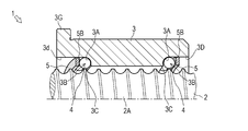
以下に、図1から図4を用いて、ボールねじ1の一実施形態であるナット3を備えるボールねじ1について説明する。本実施形態において、ボールねじ1のナット3の内周面には、軸方向両側の端部を拡径した段差形状のナット側ねじ溝3Aがそれぞれ形成されている。
図1と図2とに示すように、ボールねじ1は、回転運動を直線運動に変換して出力するものである。ボールねじ1は、ねじ軸2、ナット3、複数のボール4等から構成されている。
ねじ軸2は、S55C等の中炭素鋼あるいはSCM415やSCM420等の肌焼き鋼からなり、高周波焼入れ、真空浸炭焼入れによって55~62HRC程度の硬化処理が施されている。ねじ軸2は、その外周面にボール4が転動するための軸側ねじ溝2Aが複数形成されている。軸側ねじ溝2Aの断面形状は、サーキュラアーク形状であってもゴシックアーク形状であっても良い。本実施形態において、ねじ軸2は、ボール4との接触角が大きくとれ、アキシアルすきまが小さく設定できるゴシックアーク形状に形成されている。これにより、ボールねじ1は、ねじ軸2の軸方向荷重に対する剛性が高くなり、かつ振動の発生を抑制することができる。
ナット3は、ねじ軸2を挿入可能な中空円筒状に形成されている。ナット3は、金属粉末を可塑状に調整し、射出成形機で成形される焼結合金から構成されている。ナット3は、金属粉とプラスチックおよびワックスからなるバインダとの混練物を金型内に加熱溶融状態で押し込む、MIM(Metal Injection Molding)により成形されている。こうしたMIMによって成形される焼結合金は、加工度が高く複雑な形状であっても容易に、かつ精度良く所望の形状及び寸法に成形することができる。金属粉として、後に浸炭焼入が可能な材質、例えば、C(炭素)が0.13wt%、Ni(ニッケル)が0.21wt%、Cr(クロム)が1.1wt%、Cu(銅)が0.04wt%、Mn(マンガン)が0.76wt%、Mo(モリブデン)が0.19wt%、Si(シリコン)が0.20wt%、残りがFe(鉄)等からなるSCM415から構成されている。また、ナット3の材料としてこれ以外にも、Niが3.0~10.0wt%含有し、加工性、耐食性に優れた材料(日本粉末冶金工業規格のFEN8)、あるいは、Cが0.07wt%、Crが17wt%、Niが4wt%、Cuが4wt%、残りがFe等からなる析出硬化系ステンレスSUS630であっても良い。このSUS630は、固溶化熱処理で20~33HRCの範囲に表面硬さを適切に上げることができ、強靭性と高硬度を確保することができる。なお、本実施形態において、ナット3は、MIMにより成形されているがこれに限定するものではなく、鍛造加工によって形成してもよい。
図2(B)に示すように、ナット3の内周面には、軸方向両側の端部を拡径した段差形状のナット側ねじ溝3Aがそれぞれ形成されている。ナット3の内周面には、中央部の縮径部分と端部の拡径部分とをつなぐ段差面がナット3のそれぞれの端部に向かうにつれて徐々に拡径する曲面からなる転動面3Bに形成されている。各段差形状に形成されているナット側ねじ溝3Aは、略一巻の右回りの螺旋状に形成されている。
図3に示すように、各段差形状に形成されているナット側ねじ溝3Aは、螺旋のリード分だけ軸方向にずれた端部が滑らかな曲面3Cで接続されている。つまり、各段差形状は、螺旋状に略一巻きされることで元の端部と隣接する位置に移動した段差面とが滑らかな曲面3Cで接続されている。これにより、各段差形状のナット側ねじ溝3Aは、段差面である転動面3Bが途切れることなく連なる円環状に形成されている。各段差形状のナット側ねじ溝3Aにおいて、螺旋によってリード分だけ軸方向にずれた段差面である転動面3Bを接続している滑らかな曲面3Cは、その周方向の中央に向かうにつれて径方向外側に向かって軸側ねじ溝2Aの溝深さよりも深い凹部3Dが形成されている。このように構成されるナット3の内周面には、滑らかな曲面3Cによって接続されている円環螺旋状の段差形状であるナット側ねじ溝3Aが形成されている。また、ナット側ねじ溝3Aは、ナット3の中央部の縮径部分からそれぞれの端部に向かうにつれて徐々に拡径する曲面からなる転動面3Bのみから構成されている。すなわち、ナット側ねじ溝3Aは、側壁が片側のみのアンダーカットフリーの溝として構成されている。ナット側ねじ溝3Aは、ねじ軸2の軸側ねじ溝2Aと同一のリードおよびピッチで形成されている。ナット3の拡径部分には、後述する案内板5を配置するための案内板位置決め部3Eとして、軸方向両側の端部をナット側ねじ溝3Aに沿うように拡径した段差形状がそれぞれ形成されている。案内板位置決め部3Eは、ナット側ねじ溝3Aよりも開口側に略一巻の右回りの螺旋状に形成されている。さらに、ナット3の拡径部分には、案内板5を固定するためのスリット3Fが案内板位置決め部3Eに沿うように形成されている。
図1、図2および図4に示すように、ナット3の内周面には、円環状の案内板5(図1、図2および図4における薄墨部分)が設けられている。案内板5は、転動体であるボール4をナット側ねじ溝3A内に保持するものである。
図4に示すように、案内板5は、略一巻の右回りの螺旋状に形成されている。案内板5は、ばね用高鋼線材や、高周波焼入れ、真空浸炭焼入れによって55~62HRC程度の硬化処理が施されている鋼材から形成されている。案内板5は、螺旋のリード分だけ軸方向にずれた部分が滑らかな曲面5Aで接続されている。さらに、案内板5の滑らかな曲面5Aは、その周方向の中央に向かうにつれて径方向外側に突出部5Bが形成されている。滑らかな曲面5Aは、ナット3のナット側ねじ溝3Aの滑らかな曲面3Cと略同一の曲面に形成されている。また、案内板5は、滑らかな曲面5Aに形成されている部分に対向する部分が開口されて略C字状に形成されている。これにより、案内板5は、開口部の両端を互いに近接させることで径方向に縮径可能に構成されている。案内板5の開口部の両端には、径方向に突出した係合部5Cが形成されている。案内板5は、ナット3の案内板位置決め部3Eによって位置決めされつつナット3に形成されているスリット3Fに係合部5Cが挿入されることでナット3の内周面に固定されている。案内板5は、ナット側ねじ溝3Aの側壁(段差面)との間をボール4が通過可能な位置に固定されている。案内板5の滑らかな曲面5Aは、ナット3の滑らかな曲面3Cに対向するように配置されている。ナット3の外周面には、その外径を部分的に拡径した段付き部である鍔部3Gが形成されている。
図4に示すように、案内板5は、略一巻の右回りの螺旋状に形成されている。案内板5は、ばね用高鋼線材や、高周波焼入れ、真空浸炭焼入れによって55~62HRC程度の硬化処理が施されている鋼材から形成されている。案内板5は、螺旋のリード分だけ軸方向にずれた部分が滑らかな曲面5Aで接続されている。さらに、案内板5の滑らかな曲面5Aは、その周方向の中央に向かうにつれて径方向外側に突出部5Bが形成されている。滑らかな曲面5Aは、ナット3のナット側ねじ溝3Aの滑らかな曲面3Cと略同一の曲面に形成されている。また、案内板5は、滑らかな曲面5Aに形成されている部分に対向する部分が開口されて略C字状に形成されている。これにより、案内板5は、開口部の両端を互いに近接させることで径方向に縮径可能に構成されている。案内板5の開口部の両端には、径方向に突出した係合部5Cが形成されている。案内板5は、ナット3の案内板位置決め部3Eによって位置決めされつつナット3に形成されているスリット3Fに係合部5Cが挿入されることでナット3の内周面に固定されている。案内板5は、ナット側ねじ溝3Aの側壁(段差面)との間をボール4が通過可能な位置に固定されている。案内板5の滑らかな曲面5Aは、ナット3の滑らかな曲面3Cに対向するように配置されている。ナット3の外周面には、その外径を部分的に拡径した段付き部である鍔部3Gが形成されている。
図2(B)と図5とに示すように、ナット3には、軸側ねじ溝2Aとナット側ねじ溝3Aとが対向するようにしてねじ軸2が挿入されている。軸側ねじ溝2Aとナット側ねじ溝3Aとから構成される空間には、転動体である複数のボール4が転動自在に収容されている。また、ナット側ねじ溝3Aは、滑らかな曲面3Cが軸側ねじ溝2Aの側壁を跨ぐように形成されている。図2(B)に示すように、ナット3のナット側ねじ溝3Aとねじ軸2の軸側ねじ溝2A間に転動自在に収容されるボール4は、接触角θでもって複列外向きのアンギュラコンタクトするように構成されている。このようにして、軸側ねじ溝2Aとナット側ねじ溝3Aとは、複数のボール4が転動する転動路を構成している。ナット3は、複数のボール4を介してねじ軸2をナット3の軸回りに回転自在に支持している。
ボールねじ1は、ナット3が回転されると転動路に収容されている複数のボール4を介してねじ軸2に回転力が伝達される。ねじ軸2は、回り止め機構により軸回りの回転が規制されている場合、ナット3の回転運動が軸側ねじ溝2Aの傾きによってねじ軸2の軸方向の直線運動に変換される。同様にして、ボールねじ1は、ねじ軸2が回転されると転動路に収容されている複数のボール4を介してナット3に回転力が伝達される。ナット3は、回り止め機構により軸回りの回転が規制されている場合、ねじ軸2の回転運動が軸側ねじ溝2Aの傾きによってナット3の軸方向の直線運動に変換される。なお、本実施形態において、ねじ軸2の軸側ねじ溝2Aとナット側ねじ溝3Aとは略一巻きとしたがこれに限定されるものではない。また、本実施形態において、ねじ軸2に形成されている軸側ねじ溝2Aは右ねじであるものとするがこれに限定されるものではない。
以下に、図2から図6を用いて、ボールねじ1のナット3におけるボール4の循環の態様について詳細に説明する。
図3から図6に示すようにナット3のナット側ねじ溝3Aは、ねじ軸2の軸側ねじ溝2Aの側壁を跨ぐようにして滑らかな曲面3Cが形成され、かつ滑らかな曲面3Cに軸側ねじ溝2Aの溝深さよりも深い凹部3Dが形成されている。
従って、図5と図6とに示すように、ナット側ねじ溝3Aの滑らかな曲面3Cに到達したボール4は、ナット側ねじ溝3Aの滑らかな曲面3Cによって軸側ねじ溝2Aの側壁に徐々に寄せられる。ボール4は、軸側ねじ溝2Aの側壁にそって軸側ねじ溝2Aの先端に向かって押し上げられる。この際、ボール4は、滑らかな曲面3Cに沿うように形成されている案内板5によって保持されているので転動路から脱落することがない。つまり、ナット側ねじ溝3Aが片側のみのアンダーカットがない溝型に形成されていても、軸側ねじ溝2Aの側壁を越えようとするボール4を安定して保持することができる。ボール4は、ナット側ねじ溝3Aの滑らかな曲面3Cよって軸側ねじ溝2Aの側壁を越えて隣りの軸側ねじ溝2Aに移動するとともに円環状のナット側ねじ溝3Aの元のねじ溝位置に戻る。つまり、転動路内のボール4は、隣りの軸側ねじ溝2Aに移動するとともに、ナット側ねじ溝3Aを一周することで転動路内を循環する。このように構成することで、ボールねじ1は、転動路内に複数のボール4を連続的に配置することができる。
従って、図5と図6とに示すように、ナット側ねじ溝3Aの滑らかな曲面3Cに到達したボール4は、ナット側ねじ溝3Aの滑らかな曲面3Cによって軸側ねじ溝2Aの側壁に徐々に寄せられる。ボール4は、軸側ねじ溝2Aの側壁にそって軸側ねじ溝2Aの先端に向かって押し上げられる。この際、ボール4は、滑らかな曲面3Cに沿うように形成されている案内板5によって保持されているので転動路から脱落することがない。つまり、ナット側ねじ溝3Aが片側のみのアンダーカットがない溝型に形成されていても、軸側ねじ溝2Aの側壁を越えようとするボール4を安定して保持することができる。ボール4は、ナット側ねじ溝3Aの滑らかな曲面3Cよって軸側ねじ溝2Aの側壁を越えて隣りの軸側ねじ溝2Aに移動するとともに円環状のナット側ねじ溝3Aの元のねじ溝位置に戻る。つまり、転動路内のボール4は、隣りの軸側ねじ溝2Aに移動するとともに、ナット側ねじ溝3Aを一周することで転動路内を循環する。このように構成することで、ボールねじ1は、転動路内に複数のボール4を連続的に配置することができる。
また、図7に示すように、ボールねじ1の別実施形態として、ナット3の形状が異なるナット7を備えるボールねじ6でもよい。本実施形態において、ボールねじ6のナット7の内周面には、軸方向両側の端部を縮径した段差形状のナット側ねじ溝7Aがそれぞれ形成されている。なお、以下の全ての実施形態に係るボールねじ1は、図1から図6に示すボールねじ1において、ボールねじ1に替えて適用されるものとして、その説明で用いた名称、図番、記号を用いることで、同じものを指すこととし、以下の実施形態において、既に説明した実施形態と同様の点に関してはその具体的説明を省略し、相違する部分を中心に説明する。
図7に示すように、ボールねじ6は、回転運動を直線運動に変換して出力するものである。ボールねじ6は、ねじ軸2、ナット7、複数のボール4等から構成されている。
ナット7の内周面には、ナット側ねじ溝7Aとして、軸方向両側の端部を縮径した段差形状のナット側ねじ溝7Aがそれぞれ形成されているナット7の内周面には、端部の縮径部分と中央部の拡径部分とをつなぐ段差面がナット7の中央部に向かうにつれて徐々に拡径する曲面からなる転動面7Bに形成されている。ナット7は、拡径部分の略中央部で二分割され、圧入ピン8を介して連結されている。なお、ナット7の連結方法は、圧入ピン8に限定するものではなく、ねじ締結等でもよい。各段差形状に形成されているナット側ねじ溝7Aは、略一巻の右回りの螺旋状に形成されている。各段差形状のナット側ねじ溝7Aは、螺旋のリード分だけ軸方向にずれた端部が図示しない滑らかな曲面で接続されている。このように構成されるナット7の内周面には、ナット7が分割されている状態で略一巻の螺旋状に加工された段差形状のナット側ねじ溝7Aが途切れることなく連なる円環状に形成されている。また、ナット側ねじ溝7Aは、側壁が片側のみのアンダーカットフリーの溝として構成されている。ナット7の拡径部分には、案内板5を配置するための案内板位置決め部7Dとして、中央の拡径部をナット側ねじ溝7Aに沿うように更に拡径した段差形状がそれぞれ形成されている。
ナット7の内周面には、略一巻の右回りの円環螺旋状の案内板5が設けられている。案内板5は転動体であるボール4をナット側ねじ溝7A内に保持するものである。案内板5は、ナット7の縮径部の内径よりも小さい外径に縮径可能に構成されている。案内板5は、ナット7の内周面に形成されている図示しないスリットによってナット7の案内板位置決め部7Dに固定されている。
以上のごとく構成することで、ボールねじ1、6は、ねじ軸2の軸側ねじ溝2Aとナット3、7の片側の側壁のみからなる略一巻の円環螺旋状のナット側ねじ溝3A、7Aとから構成される転動路に複数のボール4が配置されている。つまり、ボールねじ1、6は、型物から形成可能なアンダーカットがないナット側ねじ溝3A、7Aが円環螺旋状に形成され、複数のボール4が循環可能に連続的に配置されている。これにより、ボールねじ1、6は、生産コストを抑制しつつ許容負荷容量を増大することができる。また、ボールねじ1、6は、ボール4の脱落を防止するための案内板5が容易に設けられる。これにより、生産コストを抑制しつつ許容負荷容量を増大することができる。
以上、ボールねじの一実施形態であるボールねじ1、6は、ナット3、7に略一巻の円環螺旋状のナット側ねじ溝3A、7Aが軸方向両側にそれぞれ形成されているものとして説明したがこれに限定されるものではなく、ナット7が型物で形成可能、かつボールが循環する構成であればよい。また、上述の実施形態は、代表的な形態を示したに過ぎず、一実施形態の骨子を逸脱しない範囲で種々変形して実施することができる。さらに種々なる形態で実施し得ることは勿論のことであり、本発明の範囲は、特許請求の範囲の記載によって示され、さらに特許請求の範囲に記載の均等の意味、および範囲内のすべての変更を含む。
本発明は、ボールねじに利用可能である。
1 ボールねじ
2 ねじ軸
3 ナット
3A ナット側ねじ溝
3C 滑らかな曲面
3D 凹部
4 ボール
5 案内板
2 ねじ軸
3 ナット
3A ナット側ねじ溝
3C 滑らかな曲面
3D 凹部
4 ボール
5 案内板
Claims (5)
- ねじ軸がナットに挿入され、前記ねじ軸のねじ溝と前記ナットのねじ溝とから構成される転動路に複数のボールが配置される循環型のボールねじであって、
前記ナットのねじ溝は、前記ナットの内周面の軸方向両側の端部を拡径または縮径するように内周面の軸方向一側と他側とにそれぞれ設けられる略一巻きの螺旋状の段差形状からなり、それぞれの前記螺旋状の段差形状において軸方向にずれた端部同士が滑らかな曲面で接続されて円環状に形成され、
前記螺旋状の段差形状の端部同士を接続している滑らかな曲面には、前記ナットの径方向外側に向かう凹部が形成され、
前記螺旋状の段差形状の段差面は、前記ねじ軸のねじ溝に対向する曲面に形成される、
循環型のボールねじ。 - 請求項1に記載の循環型のボールねじであって、
前記ナットの内周面の拡径部分には、円環状の案内板が設けられ、
前記案内板のうち前記螺旋状の段差形状の端部同士を接続している滑らかな曲面に対向する部分は、前記ボールが前記螺旋状の段差形状の端部同士を接続している滑らかな曲面に沿って転動するように、前記螺旋状の段差形状に沿う滑らかな曲面に形成される、
循環型のボールねじ。 - 請求項1または請求項2に記載の循環型のボールねじであって、
前記円環状の案内板の一部は、開口されて径方向に縮径可能に形成される、
循環型のボールねじ。 - 請求項1から請求項3のいずれか一項に記載の循環型のボールねじであって、
前記円環状の案内板は、前記ナットの内周面に形成されているスリットに係合される、
循環型のボールねじ。 - 請求項1から請求項4のいずれか一項に記載の循環型のボールねじであって、
前記円環状の案内板がばね用高鋼線材から構成される、
循環型のボールねじ。
Applications Claiming Priority (2)
| Application Number | Priority Date | Filing Date | Title |
|---|---|---|---|
| JP2016016247A JP2017133669A (ja) | 2016-01-29 | 2016-01-29 | ボールねじ |
| JP2016-016247 | 2016-01-29 |
Publications (1)
| Publication Number | Publication Date |
|---|---|
| WO2017130951A1 true WO2017130951A1 (ja) | 2017-08-03 |
Family
ID=59398016
Family Applications (1)
| Application Number | Title | Priority Date | Filing Date |
|---|---|---|---|
| PCT/JP2017/002312 Ceased WO2017130951A1 (ja) | 2016-01-29 | 2017-01-24 | ボールねじ |
Country Status (2)
| Country | Link |
|---|---|
| JP (1) | JP2017133669A (ja) |
| WO (1) | WO2017130951A1 (ja) |
Families Citing this family (1)
| Publication number | Priority date | Publication date | Assignee | Title |
|---|---|---|---|---|
| KR101939728B1 (ko) * | 2017-08-04 | 2019-01-17 | 주식회사 배성 | 스터드볼트 제조방법 |
Citations (1)
| Publication number | Priority date | Publication date | Assignee | Title |
|---|---|---|---|---|
| WO2007029716A1 (ja) * | 2005-09-05 | 2007-03-15 | Nsk Ltd. | ボールねじ機構及びボールねじの組立方法 |
-
2016
- 2016-01-29 JP JP2016016247A patent/JP2017133669A/ja active Pending
-
2017
- 2017-01-24 WO PCT/JP2017/002312 patent/WO2017130951A1/ja not_active Ceased
Patent Citations (1)
| Publication number | Priority date | Publication date | Assignee | Title |
|---|---|---|---|---|
| WO2007029716A1 (ja) * | 2005-09-05 | 2007-03-15 | Nsk Ltd. | ボールねじ機構及びボールねじの組立方法 |
Also Published As
| Publication number | Publication date |
|---|---|
| JP2017133669A (ja) | 2017-08-03 |
Similar Documents
| Publication | Publication Date | Title |
|---|---|---|
| JP6091149B2 (ja) | 電動リニアアクチュエータ | |
| US10274062B2 (en) | Ball screw | |
| CN108027027B (zh) | 滚珠丝杠 | |
| WO2017130951A1 (ja) | ボールねじ | |
| JP2012039765A (ja) | 電動アクチュエータ | |
| JP6074192B2 (ja) | 電動リニアアクチュエータ | |
| JP5982220B2 (ja) | 電動リニアアクチュエータ | |
| WO2016052477A1 (ja) | 電動アクチュエータ | |
| JP2010001970A (ja) | 駒式ボールねじ | |
| JP5573270B2 (ja) | ボールねじ | |
| JP2017032124A (ja) | ボールねじ | |
| EP2208902B1 (en) | A supporting structure of ball screw shaft | |
| JP2016098905A (ja) | 駒式ボールねじ | |
| JP2018053971A (ja) | ボールねじ | |
| JP2014181772A (ja) | 電動リニアアクチュエータ | |
| JP4467349B2 (ja) | 自動車用ボールねじ | |
| JP2016161087A (ja) | 電動リニアアクチュエータ | |
| WO2016125825A1 (ja) | 駒式ボールねじおよびその製造方法 | |
| JP2016142378A (ja) | 駒式ボールねじ | |
| JP2016188674A (ja) | ボールねじ | |
| JP2017137962A (ja) | 電動アクチュエータ | |
| JP2018040455A (ja) | ボールねじ | |
| JP2006242252A (ja) | ボールねじ機構 | |
| JP2016109205A (ja) | ボールねじ装置 | |
| JP4784132B2 (ja) | ボールねじ機構 |
Legal Events
| Date | Code | Title | Description |
|---|---|---|---|
| 121 | Ep: the epo has been informed by wipo that ep was designated in this application |
Ref document number: 17744181 Country of ref document: EP Kind code of ref document: A1 |
|
| NENP | Non-entry into the national phase |
Ref country code: DE |
|
| 122 | Ep: pct application non-entry in european phase |
Ref document number: 17744181 Country of ref document: EP Kind code of ref document: A1 |