WO2017130916A1 - 複数の配管を有するアキュムレータおよび圧縮機 - Google Patents
複数の配管を有するアキュムレータおよび圧縮機 Download PDFInfo
- Publication number
- WO2017130916A1 WO2017130916A1 PCT/JP2017/002177 JP2017002177W WO2017130916A1 WO 2017130916 A1 WO2017130916 A1 WO 2017130916A1 JP 2017002177 W JP2017002177 W JP 2017002177W WO 2017130916 A1 WO2017130916 A1 WO 2017130916A1
- Authority
- WO
- WIPO (PCT)
- Prior art keywords
- container
- pipes
- accumulator
- pipe
- height
- Prior art date
- Legal status (The legal status is an assumption and is not a legal conclusion. Google has not performed a legal analysis and makes no representation as to the accuracy of the status listed.)
- Ceased
Links
Images


Classifications
-
- F—MECHANICAL ENGINEERING; LIGHTING; HEATING; WEAPONS; BLASTING
- F04—POSITIVE - DISPLACEMENT MACHINES FOR LIQUIDS; PUMPS FOR LIQUIDS OR ELASTIC FLUIDS
- F04C—ROTARY-PISTON, OR OSCILLATING-PISTON, POSITIVE-DISPLACEMENT MACHINES FOR LIQUIDS; ROTARY-PISTON, OR OSCILLATING-PISTON, POSITIVE-DISPLACEMENT PUMPS
- F04C23/00—Combinations of two or more pumps, each being of rotary-piston or oscillating-piston type, specially adapted for elastic fluids; Pumping installations specially adapted for elastic fluids; Multi-stage pumps specially adapted for elastic fluids
- F04C23/008—Hermetic pumps
-
- F—MECHANICAL ENGINEERING; LIGHTING; HEATING; WEAPONS; BLASTING
- F04—POSITIVE - DISPLACEMENT MACHINES FOR LIQUIDS; PUMPS FOR LIQUIDS OR ELASTIC FLUIDS
- F04B—POSITIVE-DISPLACEMENT MACHINES FOR LIQUIDS; PUMPS
- F04B39/00—Component parts, details, or accessories, of pumps or pumping systems specially adapted for elastic fluids, not otherwise provided for in, or of interest apart from, groups F04B25/00 - F04B37/00
- F04B39/0027—Pulsation and noise damping means
- F04B39/0033—Pulsation and noise damping means with encapsulations
- F04B39/0038—Pulsation and noise damping means with encapsulations of inlet or outlet channels
-
- F—MECHANICAL ENGINEERING; LIGHTING; HEATING; WEAPONS; BLASTING
- F04—POSITIVE - DISPLACEMENT MACHINES FOR LIQUIDS; PUMPS FOR LIQUIDS OR ELASTIC FLUIDS
- F04B—POSITIVE-DISPLACEMENT MACHINES FOR LIQUIDS; PUMPS
- F04B39/00—Component parts, details, or accessories, of pumps or pumping systems specially adapted for elastic fluids, not otherwise provided for in, or of interest apart from, groups F04B25/00 - F04B37/00
- F04B39/0027—Pulsation and noise damping means
- F04B39/0055—Pulsation and noise damping means with a special shape of fluid passage, e.g. bends, throttles, diameter changes, pipes
- F04B39/0072—Pulsation and noise damping means with a special shape of fluid passage, e.g. bends, throttles, diameter changes, pipes characterised by assembly or mounting
-
- F—MECHANICAL ENGINEERING; LIGHTING; HEATING; WEAPONS; BLASTING
- F25—REFRIGERATION OR COOLING; COMBINED HEATING AND REFRIGERATION SYSTEMS; HEAT PUMP SYSTEMS; MANUFACTURE OR STORAGE OF ICE; LIQUEFACTION SOLIDIFICATION OF GASES
- F25B—REFRIGERATION MACHINES, PLANTS OR SYSTEMS; COMBINED HEATING AND REFRIGERATION SYSTEMS; HEAT PUMP SYSTEMS
- F25B43/00—Arrangements for separating or purifying gases or liquids; Arrangements for vaporising the residuum of liquid refrigerant, e.g. by heat
- F25B43/006—Accumulators
-
- F—MECHANICAL ENGINEERING; LIGHTING; HEATING; WEAPONS; BLASTING
- F04—POSITIVE - DISPLACEMENT MACHINES FOR LIQUIDS; PUMPS FOR LIQUIDS OR ELASTIC FLUIDS
- F04C—ROTARY-PISTON, OR OSCILLATING-PISTON, POSITIVE-DISPLACEMENT MACHINES FOR LIQUIDS; ROTARY-PISTON, OR OSCILLATING-PISTON, POSITIVE-DISPLACEMENT PUMPS
- F04C18/00—Rotary-piston pumps specially adapted for elastic fluids
- F04C18/30—Rotary-piston pumps specially adapted for elastic fluids having the characteristics covered by two or more of groups F04C18/02, F04C18/08, F04C18/22, F04C18/24, F04C18/48, or having the characteristics covered by one of these groups together with some other type of movement between co-operating members
- F04C18/34—Rotary-piston pumps specially adapted for elastic fluids having the characteristics covered by two or more of groups F04C18/02, F04C18/08, F04C18/22, F04C18/24, F04C18/48, or having the characteristics covered by one of these groups together with some other type of movement between co-operating members having the movement defined in group F04C18/08 or F04C18/22 and relative reciprocation between the co-operating members
- F04C18/356—Rotary-piston pumps specially adapted for elastic fluids having the characteristics covered by two or more of groups F04C18/02, F04C18/08, F04C18/22, F04C18/24, F04C18/48, or having the characteristics covered by one of these groups together with some other type of movement between co-operating members having the movement defined in group F04C18/08 or F04C18/22 and relative reciprocation between the co-operating members with vanes reciprocating with respect to the outer member
-
- F—MECHANICAL ENGINEERING; LIGHTING; HEATING; WEAPONS; BLASTING
- F04—POSITIVE - DISPLACEMENT MACHINES FOR LIQUIDS; PUMPS FOR LIQUIDS OR ELASTIC FLUIDS
- F04C—ROTARY-PISTON, OR OSCILLATING-PISTON, POSITIVE-DISPLACEMENT MACHINES FOR LIQUIDS; ROTARY-PISTON, OR OSCILLATING-PISTON, POSITIVE-DISPLACEMENT PUMPS
- F04C2240/00—Components
- F04C2240/80—Other components
- F04C2240/804—Accumulators for refrigerant circuits
-
- F—MECHANICAL ENGINEERING; LIGHTING; HEATING; WEAPONS; BLASTING
- F04—POSITIVE - DISPLACEMENT MACHINES FOR LIQUIDS; PUMPS FOR LIQUIDS OR ELASTIC FLUIDS
- F04C—ROTARY-PISTON, OR OSCILLATING-PISTON, POSITIVE-DISPLACEMENT MACHINES FOR LIQUIDS; ROTARY-PISTON, OR OSCILLATING-PISTON, POSITIVE-DISPLACEMENT PUMPS
- F04C2240/00—Components
- F04C2240/80—Other components
- F04C2240/805—Fastening means, e.g. bolts
-
- F—MECHANICAL ENGINEERING; LIGHTING; HEATING; WEAPONS; BLASTING
- F04—POSITIVE - DISPLACEMENT MACHINES FOR LIQUIDS; PUMPS FOR LIQUIDS OR ELASTIC FLUIDS
- F04C—ROTARY-PISTON, OR OSCILLATING-PISTON, POSITIVE-DISPLACEMENT MACHINES FOR LIQUIDS; ROTARY-PISTON, OR OSCILLATING-PISTON, POSITIVE-DISPLACEMENT PUMPS
- F04C2240/00—Components
- F04C2240/80—Other components
- F04C2240/806—Pipes for fluids; Fittings therefor
-
- F—MECHANICAL ENGINEERING; LIGHTING; HEATING; WEAPONS; BLASTING
- F04—POSITIVE - DISPLACEMENT MACHINES FOR LIQUIDS; PUMPS FOR LIQUIDS OR ELASTIC FLUIDS
- F04C—ROTARY-PISTON, OR OSCILLATING-PISTON, POSITIVE-DISPLACEMENT MACHINES FOR LIQUIDS; ROTARY-PISTON, OR OSCILLATING-PISTON, POSITIVE-DISPLACEMENT PUMPS
- F04C2270/00—Control; Monitoring or safety arrangements
- F04C2270/12—Vibration
-
- F—MECHANICAL ENGINEERING; LIGHTING; HEATING; WEAPONS; BLASTING
- F04—POSITIVE - DISPLACEMENT MACHINES FOR LIQUIDS; PUMPS FOR LIQUIDS OR ELASTIC FLUIDS
- F04C—ROTARY-PISTON, OR OSCILLATING-PISTON, POSITIVE-DISPLACEMENT MACHINES FOR LIQUIDS; ROTARY-PISTON, OR OSCILLATING-PISTON, POSITIVE-DISPLACEMENT PUMPS
- F04C29/00—Component parts, details or accessories of pumps or pumping installations, not provided for in groups F04C18/00 - F04C28/00
- F04C29/12—Arrangements for admission or discharge of the working fluid, e.g. constructional features of the inlet or outlet
-
- F—MECHANICAL ENGINEERING; LIGHTING; HEATING; WEAPONS; BLASTING
- F25—REFRIGERATION OR COOLING; COMBINED HEATING AND REFRIGERATION SYSTEMS; HEAT PUMP SYSTEMS; MANUFACTURE OR STORAGE OF ICE; LIQUEFACTION SOLIDIFICATION OF GASES
- F25B—REFRIGERATION MACHINES, PLANTS OR SYSTEMS; COMBINED HEATING AND REFRIGERATION SYSTEMS; HEAT PUMP SYSTEMS
- F25B1/00—Compression machines, plants or systems with non-reversible cycle
- F25B1/10—Compression machines, plants or systems with non-reversible cycle with multi-stage compression
-
- F—MECHANICAL ENGINEERING; LIGHTING; HEATING; WEAPONS; BLASTING
- F25—REFRIGERATION OR COOLING; COMBINED HEATING AND REFRIGERATION SYSTEMS; HEAT PUMP SYSTEMS; MANUFACTURE OR STORAGE OF ICE; LIQUEFACTION SOLIDIFICATION OF GASES
- F25B—REFRIGERATION MACHINES, PLANTS OR SYSTEMS; COMBINED HEATING AND REFRIGERATION SYSTEMS; HEAT PUMP SYSTEMS
- F25B31/00—Compressor arrangements
- F25B31/02—Compressor arrangements of motor-compressor units
- F25B31/023—Compressor arrangements of motor-compressor units with compressor of reciprocating-piston type
Definitions
- the present invention relates to an accumulator having a plurality of pipes, and a compressor to which the plurality of pipes of the accumulator are connected.
- a compressor that has two rotary compression mechanisms and a motor and sucks gas refrigerant from the accumulator (gas-liquid separator) into the cylinder of each compression mechanism is used for air conditioners, refrigerators, etc. It is done.
- the accumulator used for the twin rotary compressor includes a container for separating the refrigerant into gas and liquid, and two pipes for introducing the gas refrigerant in the container into the compressor.
- the stay which fixes two piping to the inner wall of a container is installed in the intermediate part of the up-down direction in a container.
- the pipe When the pipe is vibrated by a torque ripple or cogging torque of the motor or a vibration source such as pulsation of the refrigerant discharged from the compression mechanism, the pipe vibrates in the container of the accumulator.
- the vibration amplitude in the vicinity of the free end (upper end) of the pipe separated from the fixed end at the bottom of the container is large.
- the piping vibrates in the container the entire accumulator including the container vibrates. Accumulators emit noise as they vibrate. In order to reduce the noise radiated from the accumulator, we want to suppress the vibration of the piping excited by the compressor.
- An object of the present invention is to provide an accumulator capable of sufficiently reducing vibration of an accumulator excited through piping, and a compressor provided with the accumulator.
- the accumulator according to the present invention mutually restrains a container for fluid-liquid separation inside, a plurality of pipes for taking out the gas phase in the container to the outside of the container, and a plurality of pipes extending in parallel in the container.
- a restraint unit is characterized in that the restraint unit is separated from the container, and restrains each part of the plurality of pipes in the container.
- the accumulator of the present invention is preferably provided with a restraint at two or more different points in the vertical direction.
- the height from the base end position which is the position of the reference lower end located at the highest position among the lower ends of the plurality of pipes, to the tip position, which is the position where the upper ends of the plurality of pipes are aligned
- the first height corresponds to the position of the first node of the third mode of vibration of the pipe
- the second height corresponds to the position of the node of the second mode of vibration of the pipe and the third mode It is preferable to correspond to the position of the second clause of
- the reference pipe which is a pipe having the reference lower end, is curved with respect to the rectilinear portion extending along the vertical direction from the inside of the container to the outside of the container through the bottom of the container and Preferably, the proximal position is the upper end of the curved portion of the reference pipe.
- the restraint unit includes a plurality of holding units for holding the plurality of pipes one by one, and a connection unit for connecting the plurality of holding units to each other.
- the connecting portion preferably has a spring portion.
- the compressor according to the present invention includes the above-described accumulator, is connected to a pipe, and includes a compression mechanism that compresses fluid sucked through the pipe, a motor that drives the compression mechanism, a compression mechanism and a motor, and supports the accumulator. And a housing.
- the compression mechanism is preferably a rotary compression mechanism including a cylinder and a piston rotor which is eccentrically rotated from the axis of the cylinder in the cylinder.
- each of the two compression mechanisms has a cylinder and a piston rotor.
- the plurality of pipings of the accumulator that vibrates in the container of the accumulator by being externally excited are restrained by the restraint portion, and the deformation of the piping and the restraint portion and the friction between the piping and the restraint portion Piping vibration is damped. Since the restraint is separated from the container of the accumulator, the vibration of the piping in the container is not directly input to the container by the restraint. Therefore, it is possible to prevent the container from being excited due to the vibration of the piping in the container, and to prevent the whole accumulator including the container from being vibrated.
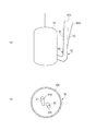
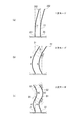
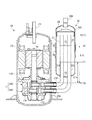
- FIG. 1 It is a longitudinal cross-sectional view which shows the rotary compressor and accumulator which concern on 1st Embodiment.
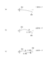
- A is a figure which shows typically the vibration analysis result of piping of the existing accumulator.
- B is a figure which shows the example which piping vibrates in a horizontal direction.
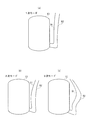
- A)-(c) is a figure showing an example of the form of a bracket.
- A) And (b) is a schematic diagram for demonstrating the vibration damping of the piping restrained by the bracket in the container of an accumulator.
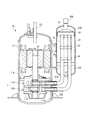
- (A)-(c) is a figure showing an example of the form of a bracket. It is a longitudinal cross-sectional view which shows the rotary compressor and accumulator which concern on 2nd Embodiment.
- FIGS. 1 to (c) are diagrams schematically showing vibration analysis results of piping of an existing accumulator.
- (A) is a figure which shows the primary mode of vibration of piping
- (b) is a figure which shows the secondary mode of vibration of piping
- (c) is a figure which shows the tertiary mode of vibration of piping .
- (A) is a figure which shows primary mode
- (b) is a figure which shows secondary mode
- (c) is a figure which shows tertiary mode.
- It is a longitudinal cross-sectional view which shows the rotary compressor and accumulator which concern on the modification of this invention. It is a longitudinal cross-sectional view which shows the rotary compressor and accumulator which concern on the other modification of this invention.
- the compressor 10 according to the first embodiment shown in FIG. 1 includes a rotary type compression mechanism 11, a motor 12 for driving the compression mechanism 11, a cylindrical housing 13 for containing the compression mechanism 11 and the motor 12, and an accumulator 20. (Gas-liquid separator).
- the compressor 10 sucks the low-pressure gas refrigerant in the accumulator 20 through the pipes 21 and 22 and compresses the refrigerant by the compression mechanism 11 to which the rotational driving force output from the motor 12 is transmitted via the crankshaft 14.
- the compressor 10 and the accumulator 20 constitute an air conditioner, a refrigeration system, and the like, and are connected to a not-shown refrigerant circuit through which the refrigerant circulates.
- the so-called twin rotary type compression mechanism 11 includes an upper compression mechanism 110, a lower compression mechanism 120, a separator plate 11A, and an upper bearing 11B and a lower bearing 11C which rotatably support the crankshaft 14.
- the upper compression mechanism 110 includes an upper crank pin 111 eccentric to the axial center of the crankshaft 14, an upper piston rotor 112, an upper cylinder 113, and an upper muffler 114.
- the upper piston rotor 112 is fitted to the outer peripheral portion of the upper crank pin 111 and is pivoted within the upper cylinder 113.
- a suction port 113A through which the gas refrigerant is sucked through the piping 21 of the accumulator 20 is formed penetrating the side wall of the upper cylinder 113 in the radial direction.
- the inside of the upper cylinder 113 and the inside of the lower cylinder 123 are partitioned by the separator plate 11A.
- the refrigerant which is drawn into the upper cylinder 113 and compressed in a space in the rotational direction ahead of the blade (not shown) pressed against the outer peripheral portion of the upper piston rotor 112 is a discharge port (not shown) formed in the upper bearing 11B. It is discharged into the housing 13 through an opening (not shown) formed in the upper muffler 114.
- the lower compression mechanism 120 also includes a lower crank pin 121, a lower piston rotor 122, a lower cylinder 123, and a lower muffler 124.
- a suction port 123A through which the gas refrigerant is sucked through the pipe 22 of the accumulator 20 is formed penetrating the side wall of the lower cylinder 123 in the radial direction.
- the lower crank pin 121 is eccentric with respect to the axial center of the crankshaft 14 in a direction opposite to the upper crank pin 111 (180 °).
- the refrigerant drawn into the lower cylinder 123 is compressed with the rotation of the lower piston rotor 122, and the housing 13 passes through a discharge port (not shown) formed in the lower bearing 11C and an opening (not shown) formed in the lower muffler 124. It is discharged into the inside.
- the refrigerant discharged into the housing 13 by the upper compression mechanism 110 and the lower compression mechanism 120 is discharged to the refrigerant circuit through the discharge pipe 131 provided at the upper portion of the housing 13.
- the accumulator 20 has a container 20A for separating the refrigerant into gas and liquid inside, and two pipings 21 and 22 for taking out the gas refrigerant which is the gas phase in the container 20A to the outside of the container 20A and sucking it into the compressor 10 And a bracket 30 (restraint portion) for mutually restraining the two pipes 21 and 22 in the container 20A.
- the container 20A is formed in a cylindrical shape, and is supported by the side wall 13A of the housing 13 of the compressor 10.
- a strap 25 is wound and tightened on the outer peripheral portion of the container 20A, and is fixed to an accumulator bracket 26 provided on the side wall 13A.
- the container 20A is cantilevered on the side wall 13A of the housing 13 by the accumulator bracket 26 and the strap 25.
- a suction pipe 20B for sucking a low-pressure refrigerant into the container 20A from a refrigerant circuit (not shown) is provided.
- the pipes 21 and 22 extend in parallel in the container 20A.
- the pipes 21 and 22 are separated from the inner wall 20W of the container 20A.
- the pipe 21 is connected to the upper compression mechanism 110, and the pipe 22 is connected to the lower compression mechanism 120.
- the piping 21 is curved with respect to the rectilinear portion 21A extending in the vertical direction (vertical direction) and a rectilinear portion 21A downward from a position separated by a predetermined distance from the upper end portion of the container 20A.
- a curved portion 21B extending toward the suction port 113A.
- the rectilinear portion 21A penetrates from the inside of the container 20A to the bottom 23 of the container 20A to reach the outside of the container 20A and continues to the curved portion 21B.
- the straight portion 21A is fixed to the bottom 23 of the container 20A by caulking the peripheral portion of the hole through which the straight portion 21A passes.
- the curved portion 21B is fixed to the side wall 13A of the housing 13 by a joint 133. The tip end of the curved portion 21B penetrates the side wall 13A and is inserted into the suction port 113A.
- the pipes 21 and 22 can be formed of an appropriate metal material of copper or iron.
- the pipe 22 also includes a straight portion 22A extending in the vertical direction, and a curved portion 22B that curves to the straight portion 22A and extends toward the suction port 123A of the lower cylinder 123.
- the straight portion 22 ⁇ / b> A extends parallel to the straight portion 21 ⁇ / b> A of the pipe 21.
- the curved portion 22B extends horizontally below the curved portion 21B of the pipe 21 and in parallel to the curved portion 21B.
- the tip end of the curved portion 22B penetrates the side wall 13A and is inserted into the suction port 123A.
- the bent portion 22C of the pipe 22 is located on the outer periphery than the bent portion 21C of the pipe 21.
- the upper end 21U of the straight portion 21A of the pipe 21 and the upper end 22U of the straight portion 22A of the pipe 22 are aligned at the same height from the bottom 23.
- a partition member 24 is provided which divides the inside of the container 20A into upper and lower parts. The partition member 24 prevents the refrigerant flowing from the suction pipe 20B into the container 20A from directly entering the pipes 21 and 22. The refrigerant flowing into the container 20A passes through an opening (not shown) formed in the partition member 24.
- the refrigerant in the container 20A is separated into a gas refrigerant which is a gas phase and a liquid refrigerant which is a liquid phase based on the density difference of the refrigerant.
- the gas refrigerant present at the upper portion in the container 20A flows into the pipes 21 and 22 from the upper end portions 21U and 22U, flows in the pipes 21 and 22 respectively, and is sucked into the compression mechanisms 110 and 120.
- the vibration is transmitted from the compressor 10 to the accumulator 20 through the pipes 21 and 22.
- the pipes 21 and 22 excited by the vibration source such as torque ripple and cogging torque of the motor 12 and pulsation of the refrigerant discharged from the compression mechanism 11 vibrate in the container 20A.
- the vibration source such as torque ripple and cogging torque of the motor 12 and pulsation of the refrigerant discharged from the compression mechanism 11 vibrate in the container 20A.
- FIG. 2A shows an example of a result of vibration analysis of the pipes 91 and 92 of the existing accumulator.
- FIG. 2A schematically shows the outer shape of the housing 13 of the rotary compressor.
- Each of the pipes 91 and 92 connected to the compressor is schematically represented by one line.
- the axis of the housing 13 of the compressor during operation stop (when not vibrating) is indicated by an alternate long and short dashed line
- the axis of the housing 13 of the compressor 10 during operation is indicated by a solid line.
- axis lines of the pipes 91 and 92 during stoppage of operation are indicated by alternate long and short dashed lines
- axes of the pipes 91 and 92 during operation are indicated by straight lines.
- the compressor vibrates due to the magnetic excitation force of the motor 12 and the pulsation of the discharged refrigerant, but piping 91 whose vibration is transmitted from the compressor through the cylinder and housing 13 of the compression mechanism. , 92 vibrates more than the compressor.
- the amplitude in the vicinity of the upper end portions 91U and 92U (free end) of each of the pipes 91 and 92 separated from the portion 93 crimped to the bottom of the accumulator container is large.
- This embodiment is provided with a bracket 30 for restraining the piping 21 and the piping 22 apart from the container 20A in the container 20A as shown in FIG. 1 in order to damp the vibrations of the pipes 21 and 22 of the accumulator 20. It is characterized by The straight portions 21A and 22A of the pipes 21 and 22 extending in the container 20A can be restrained by one or more brackets 30.
- the bracket 30 is provided at one place in the longitudinal direction (vertical direction) of the rectilinear portions 21A and 22A.
- the bracket 30 is separated from the inner wall 20W of the container 20A and is not fixed to the container 20A, and mutually restrains the rectilinear portions 21A and 22A extending in the container 20A.
- the bracket 30 holds the cylindrical holding portion 31 for holding the outer peripheral portion of the rectilinear portion 21A inserted inside, and the outer peripheral portion of the rectilinear portion 22A inserted inside as well. And a plate-like connecting portion 33 connecting the holding portion 31 and the holding portion 32.
- the holding portion 31, the holding portion 32, and the connecting portion 33 are integrally formed of an appropriate resin material or an appropriate metal material.
- the bracket 30 preferably has appropriate elasticity.
- the holding portion 31 is fixed to a predetermined portion of the rectilinear portion 21A in the vertical direction.
- the holding portion 32 is also fixed to a predetermined portion of the rectilinear portion 22A in the vertical direction.
- the holding parts 31 and 32 are located at the same height from the bottom 23 of the container 20A. Note that the heights of the holding portions 31 and 32 may be slightly different.
- the connecting portion 33 extends between the holding portion 31 and the holding portion 32.
- the connecting portion 33 is disposed along the vertical direction, and the rigidity in the vertical direction of the connecting portion 33 is high, so that the vibration damping effect due to the deformation of the connecting portion 33 at the time of vibration in the vertical direction is high.
- the holding portion 31 is preferably fixed in a state of being in close contact with the outer peripheral portion of the straight moving portion 21A by, for example, the straight moving portion 21A being press-fitted inside the holding portion 31. Then, the friction between the holding portion 31 and the rectilinear portion 21A is increased, and the effect of vibration damping by the bracket 30 is improved.
- an elastic member is interposed between the inner peripheral portion of the holding portion 31 and the outer peripheral portion of the straight moving portion 21A.
- the outer peripheral portions of the rectilinear portions 21A may be in close contact with each other. The same applies to the holding portion 32 and the rectilinear portion 22A.
- bracket 30 shown in the present embodiment is merely an example, and the bracket 30 having an appropriate form can be adopted as long as the pipes 21 and 22 are restrained in the container 20A in a state of being separated from the container 20A.
- the straight parts 21A of the pipes 21 move downward and the straight parts of the pipes 22 move downward.
- the straight portions 21A, 22A are relatively displaced in the length direction such that 22A is at the top. Since the rectilinear portions 21A, 22A are mutually restrained by the bracket 30, as the rectilinear portions 21A, 22A respectively slide inside the holding portions 31, 32, as shown in FIG. 4 (b), the rectilinear portions 21A, 22A. And the bracket 30 is deformed. Vibrations of the pipes 21 and 22 are attenuated by the deformation of the straight portions 21A and 22A and the bracket 30, and the friction between the straight portions 21A and the holding portion 31, and between the straight portions 22A and the holding portion 32.
- the bracket 30 since the bracket 30 is separated from the container 20A, the vibration of the pipes 21 and 22 in the container 20A is directly input to the container 20A by the bracket 30, unlike the case where the bracket 30 is in contact with the container 20A. It will not be done. That is, it is possible to prevent the container 20A from being vibrated by the vibrations of the pipes 21 and 22 in the container 20A, and to prevent the entire accumulator 20 including the container 20A from being vibrated.
- the vibration of the accumulator 20 can be reduced by providing the bracket 30 for restraining the pipes 21 and 22 in a state of being separated from the container 20A.
- the level of the sound pressure radiated from the accumulator 20 is reduced, so that noise can be suppressed.
- a system for propagating vibration from the compressor 10, which is a vibration source, to the accumulator 20 is applied to the pipes 21 and 22 in the container 20A. It is possible to stop the vibration of the pipes 21 and 22 from being transmitted to the outside of the container 20A and the container 20A as much as possible.
- the pipes 21 and 22 Since the vibration of the pipes 21 and 22 is surely damped and the system of vibration propagation is fixed to the pipes 21 and 22 in the container 20A, the pipes 21 and 22 having a large relative displacement distance due to the relative vibration of the pipes 21 and 22 It is preferable to restrain the two parts by the bracket 30.
- the bracket 35 illustrated in FIG. 3B includes holding portions 351 and 352 that have a C-shape when viewed in the vertical direction, and a connecting portion 33 that connects the holding portions 351 and 352.
- the bracket 35 is formed by punching a sheet metal material and bending the both ends into a point-symmetrical C-shape. Portions bent at both ends of the connecting portion 33 correspond to the holding portions 351 and 352.
- the holding portions 351 and 352 are C-shaped, and there is a gap Sp adjacent to the connecting portion 33. Therefore, when the pipes 21 and 22 to be held vibrate, the holding portions 351 and 352 can be opened and closed.
- the bracket 35 of FIG. 3B is easy to manufacture, and moreover, since the holding portions 351 and 352 are deformed by opening and closing, the effect of vibration damping is high.
- the bracket 36 shown in FIG. 3C has a connecting portion 361 disposed along the horizontal direction, and holding portions 31 and 32 connected by the connecting portion 361. Since the rigidity in the horizontal direction of the connection portion 361 is high, the bracket 36 is effective for damping the horizontal vibration of the pipes 21 and 22 as shown in FIG. 2 (b). In addition, the rigidity in the horizontal direction can be adjusted to adjust the natural frequency from the viewpoint of resonance avoidance.
- the brackets 30, 35 and 36 shown in FIGS. 3A to 3C have spring portions respectively.
- the spring portion 101 provided in each of the bracket 37 shown in FIG. 5A and the bracket 38 shown in FIG. 5B is formed in a bellows shape in the connecting portion 33 by bending. By elastically deforming the spring portion 101, the vibration damping effect by the brackets 37 and 38 is improved.
- the spring portion 102 provided in the bracket 39 shown in FIG. 5C is also formed in a bellows shape in the connecting portion 361 by bending. By elastically deforming the spring portion 102, the vibration damping effect by the bracket 39 is improved.
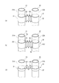
- the accumulator 40 of the second embodiment includes brackets 41 and 42 at two different places in the longitudinal direction of the straight portions 21A and 22A of the pipes 21 and 22.
- the brackets 41 and 42 can be configured in the same manner as the bracket 30 (FIG. 3A) described in the first embodiment.
- the brackets 41 and 42 may be configured in the same manner as the brackets 37 to 39 shown in FIGS. 3 (b) and 3 (c) and FIGS. 5 (a) to 5 (c).
- the brackets 41 and 42 are disposed at a predetermined height in order to obtain a sufficient vibration damping effect.
- a position at which the upper ends 21U and 22U of each of the pipes 21 and 22 are arranged Assuming that the height to P2 (tip position) is “1”, the bracket 41 is located at a height of about 0.5 (first height H1), and the bracket 42 is at a height of about 0.8 (second Located at height H2).
- the bracket 41 restrains the first portion 211 of the pipe 21 and the first portion 221 of the pipe 22.
- the first portion 211 and the first portion 221 are at the same height.
- the bracket 42 restrains the second portion 212 of the pipe 21 and the second portion 222 of the pipe 22.
- the second portion 212 and the second portion 222 are at the same height.
- the dimensions of each of the brackets 41 and 42 in the vertical direction can be set to an appropriate dimension of 1 mm or more in order to exert a restraining force on the pipes 21 and 22.
- the base end position P1 of the pipe 21 (reference pipe) having the reference lower end 21L of the lower ends 21L and 22L of the pipes 21 and 22. This is the upper end of the curved portion 21B.
- the bracket 41 is disposed over a range including the height H1 of 0.5 and the vicinity of the height H1 when the height from the proximal end position P1 to the distal end position P2 is “1”.
- the bracket 42 is disposed over a range including the height H2 of 0.8 and the vicinity of the height H2. More specifically, speaking of the dimensions of the brackets 41 and 42, with respect to the bracket 41, the central portion of the bracket 41 in the vertical direction D1 in which the rectilinear portion 21A extends is at a height H1 of about 0.5 Is preferred.
- the bracket 42 it is preferable that the central portion of the bracket 42 in the vertical direction D1 be at a height H2 of about 0.8.
- FIGS. 7 (a) to 7 (c) show the vibration analysis results of the existing (without piping bracket) accumulator pipes 91 and 92 connected to the rotary compressor.
- FIG. 7 (a) shows a primary vibration mode component
- FIG. 7 (b) shows a secondary vibration mode component
- FIG. 7 (c) shows a tertiary vibration mode component.
- vibration mode components of the fourth and higher order exist, the frequency is low and the sound pressure level is high in the entire vibration of the pipes 91 and 92, and the first to third vibrations leading to noise are mainly damped. I want to.
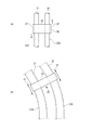
- the pipes 21 and 22 each have a fixed end 201 and a free end 202 crimped to the bottom 23 (FIG. 6) of the container 20A.
- 8 (a) to 8 (c) respectively show primary, secondary and tertiary vibration mode components.
- the amplitude gradually increases as the free end 202 is approached, and as the amplitude increases, the portion of the pipe 21 and the pipe 22 having the same height from the fixed end 201 The relative displacement with the site increases.
- FIG. 8C In the third vibration mode shown in FIG. 8C, there are two nodes B1 and B2 and two belly A1 and A2, but the height from the fixed end 201 is the same as in the second vibration mode.
- the relative displacement between the portion of the pipe 21 and the portion of the pipe 22 is maximized at the positions of the nodes B1 and B2.
- the arrows shown in FIG. 8C indicate the portions of the joints B1 and B2 of the pipe 22 with respect to the portions B1 and B2 of the pipe 21 with respect to the portions of the pipes 21 and 22 restrained by the brackets (two-dot chain line). It indicates the relative displacement direction. As shown by a two-dot chain line in FIG.
- the pipes 21 and 22 are restrained by the bracket at two places, a place corresponding to the first node B1 and a place corresponding to the second node B2. Also, the vibration damping effect due to the deformation and friction of the pipes 21 and 22 and the bracket with respect to the third mode is the highest.
- the positions of the nodes B of the secondary vibration mode and the positions of the nodes B1 and B2 of the third vibration mode are calculated based on basic equations.
- 9 (a) to 9 (c) respectively show primary, secondary and tertiary vibration mode components.
- the node B of the secondary vibration mode has a length from the fixed end 201 to the free end 202. Is “1”, it is located at “0.774”.
- the length from the fixed end 201 to the free end 202 is “1”
- the third vibration mode node B1 is located at "0.500”
- the third vibration mode node B2 is located at "0.868”.
- the amplitude is maximized at the free end 202, that is, at the position of “1”, and the relative displacement of the pipes 21 and 22 is maximized accordingly.
- two points of height H2 of 0.8 may be disposed one by one at the heights H1 and H2 based on the heights H1 and H2.
- the vibration of the pipes 21 and 22 can be efficiently damped.
- the portions are restrained by the brackets 41 and 42 at the height including the position of the node at which the relative displacement amount of the pipes 21 and 22 at the same height is the largest.
- the vibration damping effect described in the form can be obtained more sufficiently.
- the accumulator 40 of 2nd Embodiment may be provided with the other bracket which restrains piping 21 and 22 comrades in container 20A.
- the configurations described in the above embodiment can be selected or changed to other configurations as appropriate without departing from the spirit of the present invention.
- the pipes 21 and 22 can be restrained by one bracket 45 over a range including both the height H1 of 0.5 and the height H2 of 0.8.
- the vibration can be attenuated more sufficiently.
- the basic concept of the present invention is, as described in the section of the first embodiment, to restrain two or more pipes with each other in the container 20A by the bracket separated from the container 20A.
- the number is not limited. Therefore, as shown in FIG. 11, the pipes 21 and 22 can be restrained within the container 20A by the three brackets 46 to 48 which are located at three places separated in the vertical direction and separated from the container 20A.
- the present invention is suitable for the accumulators 20 and 40 including the two pipes 21 and 22 corresponding to the two cylinders 113 and 123 of the twin rotary compression mechanism 11 as in the above-described embodiments, but this configuration is not always necessary. It is not limited to The present invention can also be applied to a rotary compressor provided with one cylinder and one piston rotor, as long as refrigerant is drawn into one cylinder from two pipes 21 and 22 of accumulators 20 and 40. .
- the accumulator of the present invention is not limited to a rotary compressor, and can be applied to other compressors such as a scroll compressor. Furthermore, the accumulator of the present invention does not necessarily have to be supported by the housing 13 of the compressor. According to the vibration damping structure of the accumulator of the present invention, it is possible to reduce the vibration of the accumulator by damping the vibration transmitted from any vibration source to the pipes 21 and 22 in the container 20A.
- the shapes of the pipes 21 and 22 of the accumulator of the present invention in particular, the shape and the arrangement outside the container 20A can be appropriately determined.
- the pipes 21 and 22 may not necessarily include the curved portions 21B and 22B. In accordance with the shape and the like of the pipes 21 and 22, it is possible to appropriately determine the reference of the height for defining the portion of the pipe to be restrained.
Landscapes
- Engineering & Computer Science (AREA)
- Mechanical Engineering (AREA)
- General Engineering & Computer Science (AREA)
- Chemical & Material Sciences (AREA)
- Analytical Chemistry (AREA)
- Power Engineering (AREA)
- Physics & Mathematics (AREA)
- Thermal Sciences (AREA)
- Compressor (AREA)
- Applications Or Details Of Rotary Compressors (AREA)
Priority Applications (2)
| Application Number | Priority Date | Filing Date | Title |
|---|---|---|---|
| CN201780003950.1A CN108351135A (zh) | 2016-01-26 | 2017-01-23 | 具有多个配管的蓄能器以及压缩机 |
| EP17744146.6A EP3364130B1 (en) | 2016-01-26 | 2017-01-23 | Accumulator having multiple pipes, and compressor |
Applications Claiming Priority (2)
| Application Number | Priority Date | Filing Date | Title |
|---|---|---|---|
| JP2016-012394 | 2016-01-26 | ||
| JP2016012394A JP6645845B2 (ja) | 2016-01-26 | 2016-01-26 | 複数の配管を有するアキュムレータおよび圧縮機 |
Publications (1)
| Publication Number | Publication Date |
|---|---|
| WO2017130916A1 true WO2017130916A1 (ja) | 2017-08-03 |
Family
ID=59397852
Family Applications (1)
| Application Number | Title | Priority Date | Filing Date |
|---|---|---|---|
| PCT/JP2017/002177 Ceased WO2017130916A1 (ja) | 2016-01-26 | 2017-01-23 | 複数の配管を有するアキュムレータおよび圧縮機 |
Country Status (4)
| Country | Link |
|---|---|
| EP (1) | EP3364130B1 (enExample) |
| JP (1) | JP6645845B2 (enExample) |
| CN (1) | CN108351135A (enExample) |
| WO (1) | WO2017130916A1 (enExample) |
Cited By (4)
| Publication number | Priority date | Publication date | Assignee | Title |
|---|---|---|---|---|
| EP3550146A1 (en) * | 2018-04-05 | 2019-10-09 | Mitsubishi Heavy Industries Thermal Systems, Ltd. | Compressor system |
| EP3567250A1 (en) * | 2018-05-11 | 2019-11-13 | Mitsubishi Heavy Industries Thermal Systems, Ltd. | Compressor system |
| WO2022092290A1 (ja) * | 2020-10-30 | 2022-05-05 | ダイキン工業株式会社 | 回転式圧縮機 |
| US12429055B2 (en) * | 2021-09-30 | 2025-09-30 | Daikin Industries, Ltd. | Compressor unit |
Families Citing this family (5)
| Publication number | Priority date | Publication date | Assignee | Title |
|---|---|---|---|---|
| JP7295414B2 (ja) * | 2019-07-24 | 2023-06-21 | ダイキン工業株式会社 | 圧縮機ユニット |
| WO2022004597A1 (ja) * | 2020-07-01 | 2022-01-06 | ダイキン工業株式会社 | 熱源ユニットおよびスクロール圧縮機 |
| JP7256421B1 (ja) * | 2021-09-30 | 2023-04-12 | ダイキン工業株式会社 | 圧縮機ユニット及び冷凍装置 |
| JP2023130738A (ja) | 2022-03-08 | 2023-09-21 | オムロン株式会社 | シール貼付システム |
| CN119737707A (zh) * | 2024-11-28 | 2025-04-01 | 南昌海立电器有限公司 | 储液器及旋转式压缩机 |
Citations (5)
| Publication number | Priority date | Publication date | Assignee | Title |
|---|---|---|---|---|
| JPH0267473A (ja) * | 1988-08-31 | 1990-03-07 | Toshiba Corp | 圧縮機 |
| JPH02128061U (enExample) * | 1989-03-30 | 1990-10-22 | ||
| JPH04103972A (ja) * | 1990-08-21 | 1992-04-06 | Sanyo Electric Co Ltd | 2気筒回転式圧縮機用のアキュムレータ |
| JPH0560080A (ja) * | 1991-08-30 | 1993-03-09 | Matsushita Electric Ind Co Ltd | 2気筒回転式圧縮機 |
| WO2012026004A1 (ja) * | 2010-08-25 | 2012-03-01 | 三菱電機株式会社 | アキュムレータ及び蒸気圧縮式冷凍サイクル装置及び気液分離方法 |
Family Cites Families (8)
| Publication number | Priority date | Publication date | Assignee | Title |
|---|---|---|---|---|
| JPS61194167U (enExample) * | 1985-05-23 | 1986-12-03 | ||
| JPH0363475A (ja) * | 1989-07-31 | 1991-03-19 | Daikin Ind Ltd | アキュムレータ |
| JPH11132600A (ja) * | 1997-10-30 | 1999-05-21 | Mitsubishi Heavy Ind Ltd | 空気調和機 |
| CN1690601A (zh) * | 2004-04-30 | 2005-11-02 | 乐金电子(天津)电器有限公司 | 空调器用储液罐 |
| CN1734200A (zh) * | 2004-08-09 | 2006-02-15 | 乐金电子(天津)电器有限公司 | 空调冷媒管支持结构 |
| KR100664295B1 (ko) * | 2005-05-19 | 2007-01-04 | 엘지전자 주식회사 | 압축기용 어큐뮬레이터의 진동소음 저감 장치 |
| CN2821494Y (zh) * | 2005-07-12 | 2006-09-27 | 乐金电子(天津)电器有限公司 | 复式旋转式压缩机用储液罐 |
| JP5887518B2 (ja) * | 2011-02-08 | 2016-03-16 | パナソニックIpマネジメント株式会社 | 気液分離器および冷凍サイクル装置 |
-
2016
- 2016-01-26 JP JP2016012394A patent/JP6645845B2/ja active Active
-
2017
- 2017-01-23 EP EP17744146.6A patent/EP3364130B1/en active Active
- 2017-01-23 WO PCT/JP2017/002177 patent/WO2017130916A1/ja not_active Ceased
- 2017-01-23 CN CN201780003950.1A patent/CN108351135A/zh active Pending
Patent Citations (5)
| Publication number | Priority date | Publication date | Assignee | Title |
|---|---|---|---|---|
| JPH0267473A (ja) * | 1988-08-31 | 1990-03-07 | Toshiba Corp | 圧縮機 |
| JPH02128061U (enExample) * | 1989-03-30 | 1990-10-22 | ||
| JPH04103972A (ja) * | 1990-08-21 | 1992-04-06 | Sanyo Electric Co Ltd | 2気筒回転式圧縮機用のアキュムレータ |
| JPH0560080A (ja) * | 1991-08-30 | 1993-03-09 | Matsushita Electric Ind Co Ltd | 2気筒回転式圧縮機 |
| WO2012026004A1 (ja) * | 2010-08-25 | 2012-03-01 | 三菱電機株式会社 | アキュムレータ及び蒸気圧縮式冷凍サイクル装置及び気液分離方法 |
Non-Patent Citations (1)
| Title |
|---|
| See also references of EP3364130A4 * |
Cited By (8)
| Publication number | Priority date | Publication date | Assignee | Title |
|---|---|---|---|---|
| EP3550146A1 (en) * | 2018-04-05 | 2019-10-09 | Mitsubishi Heavy Industries Thermal Systems, Ltd. | Compressor system |
| JP2019183702A (ja) * | 2018-04-05 | 2019-10-24 | 三菱重工サーマルシステムズ株式会社 | 圧縮機システム |
| JP7080092B2 (ja) | 2018-04-05 | 2022-06-03 | 三菱重工サーマルシステムズ株式会社 | 圧縮機システム |
| EP3567250A1 (en) * | 2018-05-11 | 2019-11-13 | Mitsubishi Heavy Industries Thermal Systems, Ltd. | Compressor system |
| WO2022092290A1 (ja) * | 2020-10-30 | 2022-05-05 | ダイキン工業株式会社 | 回転式圧縮機 |
| JP2022072831A (ja) * | 2020-10-30 | 2022-05-17 | ダイキン工業株式会社 | 回転式圧縮機 |
| JP7206506B2 (ja) | 2020-10-30 | 2023-01-18 | ダイキン工業株式会社 | 回転式圧縮機 |
| US12429055B2 (en) * | 2021-09-30 | 2025-09-30 | Daikin Industries, Ltd. | Compressor unit |
Also Published As
| Publication number | Publication date |
|---|---|
| EP3364130A4 (en) | 2018-11-21 |
| JP2017133725A (ja) | 2017-08-03 |
| CN108351135A (zh) | 2018-07-31 |
| JP6645845B2 (ja) | 2020-02-14 |
| EP3364130A1 (en) | 2018-08-22 |
| EP3364130B1 (en) | 2023-02-15 |
Similar Documents
| Publication | Publication Date | Title |
|---|---|---|
| JP6645845B2 (ja) | 複数の配管を有するアキュムレータおよび圧縮機 | |
| CN103161713B (zh) | 电动压缩机 | |
| CN112005011B (zh) | 具有排出消音器的封闭式压缩机 | |
| CN104121163A (zh) | 压缩机用消音器及具有该压缩机用消音器的压缩机 | |
| CN106415007B (zh) | 电动压缩机 | |
| JP6677948B2 (ja) | 密閉型圧縮機および冷凍装置 | |
| CN101605992B (zh) | 用于压缩机壳体的底座 | |
| KR101718037B1 (ko) | 밀폐형 압축기 | |
| JP6130642B2 (ja) | 圧縮機 | |
| CN115917157A (zh) | 热源单元和涡旋压缩机 | |
| JP2005195023A (ja) | 外部防振構造を有するリニア圧縮機 | |
| CN101275566A (zh) | 密封式压缩机 | |
| JP2008292096A (ja) | 冷蔵庫 | |
| JP2012117392A (ja) | スクロール圧縮機 | |
| CN119032230A (zh) | 减振装置和使用该减振装置的密闭型压缩机 | |
| EP4130479A1 (en) | Accumulator | |
| JP5934880B2 (ja) | 密閉型圧縮機 | |
| KR100850593B1 (ko) | 리니어 압축기 | |
| CN205190230U (zh) | 消声器和压缩机构 | |
| JP7295414B2 (ja) | 圧縮機ユニット | |
| KR102162335B1 (ko) | 리니어 압축기 | |
| JP6383335B2 (ja) | 電動圧縮機 | |
| KR100608699B1 (ko) | 왕복동식 압축기의 진동 저감 장치 | |
| JP2016160758A (ja) | 密閉型圧縮機およびそれを備えた冷凍装置 | |
| JP2000145634A (ja) | 密閉形電動圧縮機 |
Legal Events
| Date | Code | Title | Description |
|---|---|---|---|
| 121 | Ep: the epo has been informed by wipo that ep was designated in this application |
Ref document number: 17744146 Country of ref document: EP Kind code of ref document: A1 |
|
| WWE | Wipo information: entry into national phase |
Ref document number: 2017744146 Country of ref document: EP |
|
| NENP | Non-entry into the national phase |
Ref country code: DE |