EP3567250A1 - Compressor system - Google Patents
Compressor system Download PDFInfo
- Publication number
- EP3567250A1 EP3567250A1 EP19170800.7A EP19170800A EP3567250A1 EP 3567250 A1 EP3567250 A1 EP 3567250A1 EP 19170800 A EP19170800 A EP 19170800A EP 3567250 A1 EP3567250 A1 EP 3567250A1
- Authority
- EP
- European Patent Office
- Prior art keywords
- compressor
- bracket
- housing
- main body
- fixed
- Prior art date
- Legal status (The legal status is an assumption and is not a legal conclusion. Google has not performed a legal analysis and makes no representation as to the accuracy of the status listed.)
- Withdrawn
Links
Images

Classifications
-
- F—MECHANICAL ENGINEERING; LIGHTING; HEATING; WEAPONS; BLASTING
- F04—POSITIVE - DISPLACEMENT MACHINES FOR LIQUIDS; PUMPS FOR LIQUIDS OR ELASTIC FLUIDS
- F04B—POSITIVE-DISPLACEMENT MACHINES FOR LIQUIDS; PUMPS
- F04B39/00—Component parts, details, or accessories, of pumps or pumping systems specially adapted for elastic fluids, not otherwise provided for in, or of interest apart from, groups F04B25/00 - F04B37/00
- F04B39/12—Casings; Cylinders; Cylinder heads; Fluid connections
- F04B39/121—Casings
-
- F—MECHANICAL ENGINEERING; LIGHTING; HEATING; WEAPONS; BLASTING
- F04—POSITIVE - DISPLACEMENT MACHINES FOR LIQUIDS; PUMPS FOR LIQUIDS OR ELASTIC FLUIDS
- F04B—POSITIVE-DISPLACEMENT MACHINES FOR LIQUIDS; PUMPS
- F04B39/00—Component parts, details, or accessories, of pumps or pumping systems specially adapted for elastic fluids, not otherwise provided for in, or of interest apart from, groups F04B25/00 - F04B37/00
- F04B39/0027—Pulsation and noise damping means
-
- F—MECHANICAL ENGINEERING; LIGHTING; HEATING; WEAPONS; BLASTING
- F04—POSITIVE - DISPLACEMENT MACHINES FOR LIQUIDS; PUMPS FOR LIQUIDS OR ELASTIC FLUIDS
- F04B—POSITIVE-DISPLACEMENT MACHINES FOR LIQUIDS; PUMPS
- F04B41/00—Pumping installations or systems specially adapted for elastic fluids
- F04B41/02—Pumping installations or systems specially adapted for elastic fluids having reservoirs
Definitions
- the present invention relates to a compressor system.
- a compressor is provided with a compression unit which compresses a fluid in a housing.
- a pressure container such as an oil pod for storing lubricating oil, an accumulator, or an oil separator is provided.
- PTL 1 discloses a configuration in which a pressure container, such as an accumulator or an oil pod, is provided on the outside of a housing of a compressor.
- the pressure containers are respectively fixed via a bracket to the outer peripheral surface of the housing of the compressor. Further, the pressure container and the compressor are connected to each other via a piping through which a refrigerant, oil, or the like flows.
- vibration of the compressor is transmitted to the pressure container via the bracket.
- vibration eigenvalue (eigenfrequency) of the pressure container
- vibration resonance
- a load is applied to the piping that connects the pressure container and the compressor to each other, and the piping is damaged.
- the present invention provides a compressor system capable of limiting vibration that occurs in a pressure container due to vibration of a compressor.
- a compressor system includes: a compressor having a compression unit that is configured to compress a fluid and a housing that stores the compression unit therein; a pressure container provided in parallel with the compressor and having a tubular portion that extends in an up-down direction and a bottom portion for closing a lower end of the tubular portion; a fixed portion for fixing the tubular portion of the pressure container to an outer surface of the housing; a piping of which one end is connected to the housing and the other end is connected to the bottom portion of the pressure container; and a base member that supports the compressor and the bottom portion of the pressure container and has greater rigidity than rigidity of the piping.
- the tubular portion is fixed to the housing by the fixed portion, and the bottom portion is supported by the base member. Accordingly, it is possible to firmly fix the pressure container to the compressor at a position separated in the up-down direction. Therefore, it becomes difficult for vibration of the compressor to be transmitted to the pressure container.
- the base member may include an external leg portion that is fixed to the housing and supports the compressor, and a bracket fixed to the bottom portion of the pressure container and connected to the external leg portion.
- the pressure container is indirectly connected to the compressor via a plurality of members of the bracket and the external leg portion. Accordingly, the vibration transmitted from the compressor to the pressure container is further attenuated by the base member. As a result, the vibration transmitted to the pressure container is further limited.
- the bracket may have a shape of a plate, and have a bent portion curved between a first fixed portion fixed to the pressure container and a second fixed portion connected to the external leg portion.
- the external leg portion may include an external leg portion main body fixed to a lower portion of the housing, and a reinforcement rib connected to an outer peripheral portion of the external leg portion main body at a position deviating from the housing when viewed from the up-down direction, and the bracket may be fixed to the reinforcement rib.
- the bracket may be welded to the external leg portion.
- the bracket in any one of the second to the fifth aspects, may be formed of the same material as a material of the external leg portion, and a plate thickness of the bracket is the same as a thickness of the external leg portion.
- the base member may be fixed to the bottom portion of the pressure container at a position at least partially overlapping the center of gravity of the pressure container when viewed from the up-down direction.
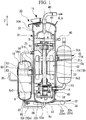
- FIG. 1 is a sectional view of a compressor system according to the embodiment of the present invention.
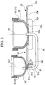
- FIG. 2 is a view of the compressor system shown in FIG. 1 when viewed from below.
- FIG. 3 is a sectional view showing a joined part between an external leg portion and a bracket in the compressor system shown in FIG. 1 .
- the compressor system 10 includes the compressor 11, a suction pipe 13, an accumulator 14, an oil pod (pressure container) 16, a pressure equalizing pipe 25, an oil supply pipe (piping) 26, and a base member 32.
- the compressor 11 includes a housing 31, a rotational shaft 33, a discharge pipe 40, an electric motor 42, a rotary compression unit (compression unit) 43, a scroll compression unit (compression unit) 44, and an injection pipe 45.
- the housing 31 extends in an up-down direction Z along an axial line Ax of the rotational shaft 33.
- the up-down direction Z indicates a vertical direction.
- the housing 31 includes a cylindrical housing main body 51, a housing upper lid portion 52 for closing the opening above the housing main body 51, and a housing lower lid portion 53 for closing the lower opening of the housing main body 51.
- the housing 31 partitions an internal space 31A that extends in the up-down direction Z.
- An oil reservoir O1 is formed by accumulating oil (lubricating oil) A in the bottom portion of the housing lower lid portion 53 from the lower portion of the housing main body 51.
- the rotational shaft 33 is accommodated in the housing 31.
- the rotational shaft 33 is disposed in the internal space 31A such that an extending direction of the axial line Ax is an up-down direction Z.
- the rotational shaft 33 is supported in a state of being rotatable around the axial line Ax by a bearing fixed to the housing 31.
- the discharge pipe 40 Apart of the discharge pipe 40 is disposed in the housing 31, and the remaining portion is disposed on the outside of the housing 31.
- the discharge pipe 40 passes through the housing upper lid portion 52.
- One end of the discharge pipe 40 has reached a space where the refrigerant (for example, a fluid, such as a gas including carbon dioxide) compressed by the scroll compression unit 44 is discharged.
- the other end of the discharge pipe 40 is disposed on the outside of the housing 31.
- the discharge pipe 40 includes the oil A and discharges a compressed refrigerant R to the outside of the housing 31.
- the electric motor 42 is accommodated in the housing 31.
- the electric motor 42 is disposed between the rotary compression unit 43 and the scroll compression unit 44 in the up-down direction Z.
- a power source (not shown) is connected to the electric motor 42.
- the electric motor 42 rotates the rotational shaft 33 by the electric power from the power source.
- the rotary compression unit 43 is provided in the lower portion in the housing 31.
- the rotary compression unit 43 is disposed below the electric motor 42.
- the refrigerant R compressed by the rotary compression unit 43 is sent to the scroll compression unit 44.
- the scroll compression unit 44 is accommodated in the housing 31 and is disposed above the electric motor 42.
- the refrigerant R compressed in a compression chamber B of the scroll compression unit 44 is discharged to the outside of the housing 31 via the discharge pipe 40.
- the injection pipe 45 is a path for introducing the refrigerant R into the housing 31 from a supply source (not shown).
- the accumulator 14 is provided on the outside of the compressor 11 along the housing 31.
- the accumulator 14 separates a liquid phase from the refrigerant R and supplies the gas phase of the refrigerant R to the rotary compression unit 43 through the suction pipe 13.
- the accumulator 14 includes a hollow accumulator main body 19 that extends in a direction of an axial line Ax2 and a first ring bracket 15.
- the accumulator main body 19 has a bottomed tubular shape such that the axial line Ax2 extends in the up-down direction Z.
- the accumulator main body 19 is fixed to the outer peripheral surface of the housing main body 51 of the housing 31 via the annular first ring bracket 15.
- the first ring bracket 15 is provided above the center position of the accumulator main body 19 in the up-down direction Z.
- the first ring bracket 15 includes a first ring portion 15a continuous in a peripheral direction along the outer peripheral surface of the accumulator main body 19 and a first belt portion 15b.
- the first ring portion 15a is bolted to a first stay 31s fixed to the outer peripheral surface of the housing main body 51.
- the first belt portion 15b is formed of a rubber material and wound around the accumulator main body 19.
- the first ring portion 15a is attached to the accumulator main body 19 from above the first belt portion 15b.
- the oil pod 16 is provided on the outside of the compressor 11 along the housing 31.
- the oil pod 16 is disposed on the side opposite to the accumulator 14 so as to be disposed with the compressor 11 interposed therebetween when viewed from the up-down direction Z.
- the oil A is stored.
- the oil pod 16 includes a hollow oil pod main body 80 that extends around an axial line Ax3, a second ring bracket (fixed portion) 18, an oil introduction pipe 20, a pressure equalizing pipe 25, and an oil supply pipe 26.
- an oil supply source for supplying the oil A from the outside of the compressor system 10 may be provided in the oil pod 16 (not shown).
- the oil pod main body 80 has a bottomed tubular shape such that the axial line Ax3 extends in the up-down direction Z.
- the oil pod main body 80 includes a pod main body portion (tubular portion) 81, a pod upper lid portion 82, and a pod lower lid portion (bottom portion) 83.
- the pod main body portion 81 is a tubular member that extends in the up-down direction Z along the axial line Ax3. In the pod main body portion 81, the upper and lower ends are opened respectively.
- the pod upper lid portion 82 is fixed to the pod main body portion 81 so as to close the opening of the upper end of the pod main body portion 81.
- the pod lower lid portion 83 is fixed to the pod main body portion 81 so as to close the opening of the lower end of the pod main body portion 81.
- the pod upper lid portion 82 and the pod lower lid portion 83 are attached to the pod main body portion 81 by welding.
- the pod main body portion 81 is fixed to the outer peripheral surface of the housing main body 51 of the housing 31 via an annular second ring bracket (fixed portion) 18.
- the second ring bracket 18 is provided above the center position of the pod main body portion 81 in the up-down direction Z.
- the second ring bracket 18 includes a second ring portion 18a continuous in the peripheral direction along the outer peripheral surface of the pod main body portion 81 and a second belt portion 18b.
- the second ring portion 18a is bolted to a second stay 31t fixed to the outer peripheral surface of the housing main body 51.
- the second belt portion 18b is formed of the same rubber material as that of the first belt portion 15b and wound around the pod main body portion 81.
- the second ring portion 18a is attached to the pod main body portion 81 from above the second belt portion 18b.
- the oil introduction pipe 20 is provided below the second ring bracket 18 and in the vicinity of the center of the pod main body portion 81 in the up-down direction Z.
- the oil introduction pipe 20 is a piping for introducing the oil A into the oil pod 16.
- the pressure equalizing pipe 25 is a pipe for keeping the internal pressure of the housing 31 and the internal pressure of the oil pod main body 80 in balance. One end of the pressure equalizing pipe 25 communicates with the inside of the housing 31. The other end of the pressure equalizing pipe 25 is connected to the pod upper lid portion 82 so as to communicate with the inside of the oil pod 16.
- the oil supply pipe 26 is connected to the housing 31 and the oil pod 16 in a state where the oil A stored in the lower portion in the housing 31 and the oil A stored in the oil pod 16 can mutually circulate.
- One end of the oil supply pipe 26 is connected to the lower end (specifically, the housing lower lid portion 53) of the housing 31.
- the other end of the oil supply pipe 26 is connected to the lower end (specifically, the pod lower lid portion 83 which will be described later) of the oil pod 16. Accordingly, the oil supply pipe 26 communicates with the inside of the housing 31 and the inside of the oil pod main body 80.
- a cylindrical piping can be used as the oil supply pipe 26 for example.
- the base member 32 is fixed to the outer peripheral surface of the housing lower lid portion 53 and the lower end of the pod lower lid portion 83.
- the base member 32 supports the compressor 11 from the lower side and supports the oil pod 16 from the lower side.
- the base member 32 has higher rigidity than that of the oil supply pipe 26.
- the base member 32 includes an external leg portion 32a and a bracket 91.
- the external leg portion 32a is fixed to the compressor 11 and supports the compressor 11 with respect to an installation surface.
- the external leg portion 32a includes an external leg portion main body 32m and reinforcement ribs 32r.
- the external leg portion main body 32m has a shape of a flat plate that extends in a direction orthogonal to the axial line Ax. As shown in FIGS. 2 and 3 , the external leg portion main body 32m has a substantially rectangular shape when viewed from the up-down direction Z. A through-hole 32h having an inner diameter smaller than an outer diameter of the housing lower lid portion 53 is formed in the center portion of the external leg portion main body 32m when viewed from the up-down direction Z.
- the housing lower lid portion 53 has a hemispherical dome-shaped portion 53a curved such that the outer diameter thereof gradually decreases downward.
- the dome-shaped portion 53a is inserted from above, and a part of the center portion thereof protrudes downward from the through-hole 32h.
- the dome-shaped portion 53a is welded to the external leg portion main body 32m at a plurality of locations in the peripheral direction at a part where the dome-shaped portion 53a abuts against an inner peripheral edge of the through-hole 32h. Accordingly, the external leg portion main body 32m is fixed to the housing 31.
- a rubber leg attachment hole 34 is formed into which a rubber leg (not shown) is inserted when placing the compressor system 10 on the installation surface of an object to be attached.
- the reinforcement ribs 32r are integrally formed on four sides of the external leg portion main body 32m.
- the reinforcement ribs 32r extend downward so as to be orthogonal to the external leg portion main body 32m.
- the reinforcing ribs 32r are connected to the outer peripheral portion of the external leg portion main body 32m at a position deviated from the housing 31 when viewed from the up-down direction Z.
- the bracket 91 is fixed to the pod lower lid portion 83 and the external leg portion 32a.
- the bracket 91 is a plate-like member formed of the same material and with the same plate thickness as those of the external leg portion 32a.
- the bracket 91 integrally includes a first fixed portion 91a, a second fixed portion 91b, and a bent portion 91c.
- the first fixed portion 91a is joined to the pod lower lid portion 83 by welding.
- the first fixed portion 91a is at the position overlapping the center portion of the pod lower lid portion 83 through which the axial line Ax3 passes when viewed from the up-down direction Z, and is welded to the lower surface orienting toward the lower side of the pod lower lid portion 83 in the up-down direction Z.
- the bracket 91 is disposed so as to overlap the center of gravity of the oil pod main body 80 vertically downward.
- the second fixed portion 91b is connected to the reinforcement ribs 32r.
- the second fixed portion 91b and the reinforcement ribs 32r are fastened by fastening bolts 93 and joined to each other by welding.
- the bent portion 91c is curved so as to be bent substantially at a right angle between the first fixed portion 91a and the second fixed portion 91b.
- bracket 91 and the reinforcement ribs 32r are connected to each other by the fastening bolts 93, and the bracket 91 with respect to the external leg portion 32a is temporarily stopped in a state of being positioned. Thereafter, the bracket 91 and the reinforcement ribs 32r are welded and fixed in a non-movable state.
- the bracket 91 is formed as short as possible. Accordingly, a holding force of the oil pod main body 80 is enhanced, and the effect of limiting vibration and the effect of limiting displacement in the direction of rotation around the axial line Ax3 are enhanced.
- the upper pod main body portion 81 is fixed to the housing 31 by the second ring bracket 18 and the lower pod lower lid portion 83 is supported by the base member 32. Accordingly, it is possible to firmly fix the oil pod main body 80 to the compressor 11 at a position separated in the up-down direction Z. Therefore, it becomes difficult for the vibration of the compressor 11 to be transmitted to the oil pod main body 80. Accordingly, it is possible to limit the vibration that occurs in the oil pod 16 due to the vibration of the compressor 11. As a result, it becomes possible to limit damage to the oil supply pipe 26 provided between the compressor 11 and the oil pod 16.
- the lower side of the oil pod main body 80 is connected to the base member 32 placed on the installation surface via the rubber leg. Accordingly, the vibration transmitted from the compressor 11 to the oil pod main body 80 is attenuated by the base member 32. In this manner, it is possible to effectively limit the vibration that occurs in the oil pod 16 due to the vibration of the compressor 11, and to limit the damage to the oil supply pipe 26 provided between the compressor 11 and the oil pod 16.
- the oil pod main body 80 is fixed to the external leg portion 32a fixed to the compressor 11 via the bracket 91. Accordingly, the oil pod 16 is indirectly connected to the compressor 11 via a plurality of members of the bracket 91 and the external leg portion 32a. Accordingly, the vibration transmitted from the compressor 11 to the oil pod main body 80 is further attenuated by the base member 32. As a result, the vibration transmitted to the oil pod 16 is further limited.
- the bracket 91 includes the bent portion 91c between the first fixed portion 91a joined to the oil pod main body 80 and the second fixed portion 91b joined to the base member 32. Accordingly, the rigidity of the bracket 91 is enhanced, and the oil pod main body 80 can be supported more firmly.
- the bracket 91 is joined to the part of the reinforcement ribs 32r having high rigidity in the base member 32 by welding. As a result, it is possible to more firmly fix the bracket 91 and the external leg portion 32a and to more stably and firmly support the oil pod main body 80 compared to a case where the bracket 91 is simply fixed only with the fastening bolts 93 or a case where the bracket 91 is fixed to the external leg portion main body 32m. Accordingly, it is possible to limit the vibration that occurs in the oil pod 16 due to the vibration of the compressor 11.
- the bracket 91 is welded to the reinforcement ribs 32r after being connected by the fastening bolts 93. Accordingly, when the bracket 91 is connected to the reinforcement ribs 32r, the bracket 91 can be temporarily stopped in a state of positioning the bracket 91 to the reinforcement ribs 32r by the fastening bolts 93. Therefore, the bracket 91 and the reinforcement ribs 32r can be welded easily and reliably.
- the bracket 91 is a member formed of the same material and with the same plate thickness as those the external leg portion 32a. Accordingly, the rigidity of the bracket 91 can be brought closer to the rigidity of the external leg portion 32a. Therefore, it is possible to limit the vibration in the bracket 91 to the utmost.
- the bracket 91 is fixed at a position overlapping the center of gravity of the oil pod main body 80 of the lower end of the pod lower lid portion 83 which is the most separated from the second ring bracket 18 in the up-down direction Z. Therefore, it is possible to limit the lower end portion where the amplitude of the vibration to be transmitted from the compressor 11 via the second ring bracket 18 becomes likely to be the largest in the oil pod main body 80. Therefore, it is possible to efficiently limit the vibration that occurs in the oil pod main body 80.
- the bracket 91 is a member formed of the same material and with the same plate thickness as those the external leg portion 32a. Accordingly, the rigidities of the bracket 91 and the external leg portion 32a can be brought closer to each other. Furthermore, it is preferable to set the material, the plate thickness, and the like such that the rigidities (cross-sectional secondary moment) are the same as each other in the bracket 91 and the external leg portion 32a. In a case where the rigidity of the bracket 91 is lower than that of the external leg portion 32a, the vibration is likely to occur in the bracket 91 due to the transmission of the vibration of the compressor 11.
- the vibration is likely to occur in the external leg portion 32a due to the transmission of the vibration of the compressor 11.
- the rigidities of the bracket 91 and the external leg portion 32a closer to each other, it is possible to limit the occurrence of the vibration in one of the bracket or the external leg portion.
- the oil pod main body 80 is connected to the base member 32 via the bracket 91, but the oil pod main body 80 may be fixed directly to the base member 32 without passing through the bracket 91.
- the present invention is not limited to such a structure.
- the accumulator 14 may be used as another pressure container, and the compressor 11 and the accumulator 14 may have a structure fixed to the base member 32 similarly to a case of the oil pod 16.
Landscapes
- Engineering & Computer Science (AREA)
- Mechanical Engineering (AREA)
- General Engineering & Computer Science (AREA)
- Compressor (AREA)
- Rotary Pumps (AREA)
- Applications Or Details Of Rotary Compressors (AREA)
Abstract
Description
- The present invention relates to a compressor system.
- A compressor is provided with a compression unit which compresses a fluid in a housing. There is a case where, on the outside of the housing of such a compressor, a pressure container, such as an oil pod for storing lubricating oil, an accumulator, or an oil separator is provided.
- PTL 1 discloses a configuration in which a pressure container, such as an accumulator or an oil pod, is provided on the outside of a housing of a compressor. The pressure containers are respectively fixed via a bracket to the outer peripheral surface of the housing of the compressor. Further, the pressure container and the compressor are connected to each other via a piping through which a refrigerant, oil, or the like flows.
- [PTL 1] Japanese Unexamined Patent Application, First Publication No.
2017-180275 - Incidentally, when the compressor operates, vibration of the compressor is transmitted to the pressure container via the bracket. Depending on an eigenvalue (eigenfrequency) of the pressure container, there is a case where vibration (resonance) occurs in a mode in which an end portion of the pressure container largely shakes due to the vibration transmitted from the compressor. When such vibration occurs, there is a case where a load is applied to the piping that connects the pressure container and the compressor to each other, and the piping is damaged.
- The present invention provides a compressor system capable of limiting vibration that occurs in a pressure container due to vibration of a compressor.
- A compressor system according to one aspect of the present invention includes: a compressor having a compression unit that is configured to compress a fluid and a housing that stores the compression unit therein; a pressure container provided in parallel with the compressor and having a tubular portion that extends in an up-down direction and a bottom portion for closing a lower end of the tubular portion; a fixed portion for fixing the tubular portion of the pressure container to an outer surface of the housing; a piping of which one end is connected to the housing and the other end is connected to the bottom portion of the pressure container; and a base member that supports the compressor and the bottom portion of the pressure container and has greater rigidity than rigidity of the piping.
- With such a configuration, in the pressure container, the tubular portion is fixed to the housing by the fixed portion, and the bottom portion is supported by the base member. Accordingly, it is possible to firmly fix the pressure container to the compressor at a position separated in the up-down direction. Therefore, it becomes difficult for vibration of the compressor to be transmitted to the pressure container.
- In addition, in the compressor system according to a second aspect of the present invention, in the first aspect, the base member may include an external leg portion that is fixed to the housing and supports the compressor, and a bracket fixed to the bottom portion of the pressure container and connected to the external leg portion.
- With such a configuration, the pressure container is indirectly connected to the compressor via a plurality of members of the bracket and the external leg portion. Accordingly, the vibration transmitted from the compressor to the pressure container is further attenuated by the base member. As a result, the vibration transmitted to the pressure container is further limited.
- In addition, in the compressor system according to a third aspect of the present invention, in the second aspect, the bracket may have a shape of a plate, and have a bent portion curved between a first fixed portion fixed to the pressure container and a second fixed portion connected to the external leg portion.
- With such a configuration, the rigidity of the bracket is enhanced.
- In addition, in the compressor system according to a fourth aspect of the present invention, in the second aspect or the third aspect, the external leg portion may include an external leg portion main body fixed to a lower portion of the housing, and a reinforcement rib connected to an outer peripheral portion of the external leg portion main body at a position deviating from the housing when viewed from the up-down direction, and the bracket may be fixed to the reinforcement rib.
- With such a configuration, it is possible to support the pressure container more firmly. Accordingly, it is possible to limit the vibration that occurs in the pressure container due to the vibration of the compressor.
- Further, in the compressor system according to a fifth aspect of the present invention, in any one of the second to the fourth aspects, the bracket may be welded to the external leg portion.
- With such a configuration, it is possible to firmly fix the bracket and the external leg portion to each other, and to support the pressure container more stably.
- Further, in the compressor system according to a sixth aspect of the present invention, in any one of the second to the fifth aspects, the bracket may be formed of the same material as a material of the external leg portion, and a plate thickness of the bracket is the same as a thickness of the external leg portion.
- With such a configuration, it is possible to bring the rigidities of the bracket and the external leg portion closer to each other. In a case where the rigidity of the bracket is lower than that of the base member, the vibration is likely to occur in the bracket due to the transmission of the vibration of the compressor. In addition, in a case where the rigidity of the base member is lower than that of the bracket, the vibration is likely to occur in the base member due to the transmission of the vibration of the compressor. However, by bringing the rigidities of the bracket and the external leg portion closer to each other, it is possible to limit the occurrence of the vibration in the bracket or the external leg portion.
- In addition, in the compressor system according to a seventh aspect of the present invention, in any one of the first to the sixth aspects, the base member may be fixed to the bottom portion of the pressure container at a position at least partially overlapping the center of gravity of the pressure container when viewed from the up-down direction.
- With such a configuration, it is possible to limit the lower end portion where an amplitude of the vibration transmitted from the compressor via the fixed portion becomes likely to be the largest in the pressure container. Therefore, it is possible to efficiently limit the vibration that occurs in the pressure container.
- According to the present invention, it becomes possible to limit the vibration that occurs in the pressure container due to the vibration of the compressor.
-
-
FIG. 1 is a sectional view of a compressor system according to an embodiment of the present invention. -
FIG. 2 is a view of the compressor system shown inFIG. 1 when viewed from below. -
FIG. 3 is a sectional view showing a joined part between an external leg portion and a bracket in the compressor system shown inFIG. 1 . - With reference to
FIG. 1 , acompressor system 10 according to an embodiment of the present invention will be described.FIG. 1 is a sectional view of a compressor system according to the embodiment of the present invention.FIG. 2 is a view of the compressor system shown inFIG. 1 when viewed from below.FIG. 3 is a sectional view showing a joined part between an external leg portion and a bracket in the compressor system shown inFIG. 1 . - In addition, in
FIG. 1 , as an example of acompressor 11, the following description will be given taking a case where a closed type two-stage compressor is used, as an example. As shown inFIG. 1 , thecompressor system 10 includes thecompressor 11, asuction pipe 13, anaccumulator 14, an oil pod (pressure container) 16, apressure equalizing pipe 25, an oil supply pipe (piping) 26, and abase member 32. - The
compressor 11 includes ahousing 31, arotational shaft 33, adischarge pipe 40, anelectric motor 42, a rotary compression unit (compression unit) 43, a scroll compression unit (compression unit) 44, and aninjection pipe 45. - The
housing 31 extends in an up-down direction Z along an axial line Ax of therotational shaft 33. In addition, inFIG. 1 , the up-down direction Z indicates a vertical direction. Thehousing 31 includes a cylindrical housingmain body 51, a housingupper lid portion 52 for closing the opening above the housingmain body 51, and a housinglower lid portion 53 for closing the lower opening of the housingmain body 51. Thehousing 31 partitions aninternal space 31A that extends in the up-down direction Z. An oil reservoir O1 is formed by accumulating oil (lubricating oil) A in the bottom portion of the housinglower lid portion 53 from the lower portion of the housingmain body 51. - The
rotational shaft 33 is accommodated in thehousing 31. Therotational shaft 33 is disposed in theinternal space 31A such that an extending direction of the axial line Ax is an up-down direction Z. Therotational shaft 33 is supported in a state of being rotatable around the axial line Ax by a bearing fixed to thehousing 31. - Apart of the
discharge pipe 40 is disposed in thehousing 31, and the remaining portion is disposed on the outside of thehousing 31. Thedischarge pipe 40 passes through the housingupper lid portion 52. One end of thedischarge pipe 40 has reached a space where the refrigerant (for example, a fluid, such as a gas including carbon dioxide) compressed by thescroll compression unit 44 is discharged. The other end of thedischarge pipe 40 is disposed on the outside of thehousing 31. Thedischarge pipe 40 includes the oil A and discharges a compressed refrigerant R to the outside of thehousing 31. - The
electric motor 42 is accommodated in thehousing 31. Theelectric motor 42 is disposed between therotary compression unit 43 and thescroll compression unit 44 in the up-down direction Z. A power source (not shown) is connected to theelectric motor 42. Theelectric motor 42 rotates therotational shaft 33 by the electric power from the power source. - The
rotary compression unit 43 is provided in the lower portion in thehousing 31. Therotary compression unit 43 is disposed below theelectric motor 42. The refrigerant R compressed by therotary compression unit 43 is sent to thescroll compression unit 44. - The
scroll compression unit 44 is accommodated in thehousing 31 and is disposed above theelectric motor 42. The refrigerant R compressed in a compression chamber B of thescroll compression unit 44 is discharged to the outside of thehousing 31 via thedischarge pipe 40. - The
injection pipe 45 is a path for introducing the refrigerant R into thehousing 31 from a supply source (not shown). - The
accumulator 14 is provided on the outside of thecompressor 11 along thehousing 31. Theaccumulator 14 separates a liquid phase from the refrigerant R and supplies the gas phase of the refrigerant R to therotary compression unit 43 through thesuction pipe 13. Theaccumulator 14 includes a hollow accumulatormain body 19 that extends in a direction of an axial line Ax2 and afirst ring bracket 15. - The accumulator
main body 19 has a bottomed tubular shape such that the axial line Ax2 extends in the up-down direction Z. The accumulatormain body 19 is fixed to the outer peripheral surface of the housingmain body 51 of thehousing 31 via the annularfirst ring bracket 15. - The
first ring bracket 15 is provided above the center position of the accumulatormain body 19 in the up-down direction Z. Thefirst ring bracket 15 includes afirst ring portion 15a continuous in a peripheral direction along the outer peripheral surface of the accumulatormain body 19 and afirst belt portion 15b. - The
first ring portion 15a is bolted to afirst stay 31s fixed to the outer peripheral surface of the housingmain body 51. Thefirst belt portion 15b is formed of a rubber material and wound around the accumulatormain body 19. Thefirst ring portion 15a is attached to the accumulatormain body 19 from above thefirst belt portion 15b. - The
oil pod 16 is provided on the outside of thecompressor 11 along thehousing 31. Theoil pod 16 is disposed on the side opposite to theaccumulator 14 so as to be disposed with thecompressor 11 interposed therebetween when viewed from the up-down direction Z. In theoil pod 16, the oil A is stored. Theoil pod 16 includes a hollow oil podmain body 80 that extends around an axial line Ax3, a second ring bracket (fixed portion) 18, anoil introduction pipe 20, apressure equalizing pipe 25, and anoil supply pipe 26. - In addition, in
FIG. 1 , an oil supply source for supplying the oil A from the outside of thecompressor system 10 may be provided in the oil pod 16 (not shown). - The oil pod
main body 80 has a bottomed tubular shape such that the axial line Ax3 extends in the up-down direction Z. The oil podmain body 80 includes a pod main body portion (tubular portion) 81, a podupper lid portion 82, and a pod lower lid portion (bottom portion) 83. - The pod main body portion 81 is a tubular member that extends in the up-down direction Z along the axial line Ax3. In the pod main body portion 81, the upper and lower ends are opened respectively. The pod
upper lid portion 82 is fixed to the pod main body portion 81 so as to close the opening of the upper end of the pod main body portion 81. The podlower lid portion 83 is fixed to the pod main body portion 81 so as to close the opening of the lower end of the pod main body portion 81. The podupper lid portion 82 and the podlower lid portion 83 are attached to the pod main body portion 81 by welding. - The pod main body portion 81 is fixed to the outer peripheral surface of the housing
main body 51 of thehousing 31 via an annular second ring bracket (fixed portion) 18. - The
second ring bracket 18 is provided above the center position of the pod main body portion 81 in the up-down direction Z. Thesecond ring bracket 18 includes asecond ring portion 18a continuous in the peripheral direction along the outer peripheral surface of the pod main body portion 81 and asecond belt portion 18b. - The
second ring portion 18a is bolted to a second stay 31t fixed to the outer peripheral surface of the housingmain body 51. Thesecond belt portion 18b is formed of the same rubber material as that of thefirst belt portion 15b and wound around the pod main body portion 81. Thesecond ring portion 18a is attached to the pod main body portion 81 from above thesecond belt portion 18b. - The
oil introduction pipe 20 is provided below thesecond ring bracket 18 and in the vicinity of the center of the pod main body portion 81 in the up-down direction Z. Theoil introduction pipe 20 is a piping for introducing the oil A into theoil pod 16. - The
pressure equalizing pipe 25 is a pipe for keeping the internal pressure of thehousing 31 and the internal pressure of the oil podmain body 80 in balance. One end of thepressure equalizing pipe 25 communicates with the inside of thehousing 31. The other end of thepressure equalizing pipe 25 is connected to the podupper lid portion 82 so as to communicate with the inside of theoil pod 16. - The
oil supply pipe 26 is connected to thehousing 31 and theoil pod 16 in a state where the oil A stored in the lower portion in thehousing 31 and the oil A stored in theoil pod 16 can mutually circulate. One end of theoil supply pipe 26 is connected to the lower end (specifically, the housing lower lid portion 53) of thehousing 31. The other end of theoil supply pipe 26 is connected to the lower end (specifically, the podlower lid portion 83 which will be described later) of theoil pod 16. Accordingly, theoil supply pipe 26 communicates with the inside of thehousing 31 and the inside of the oil podmain body 80. As theoil supply pipe 26, for example, a cylindrical piping can be used. - As shown in
FIGS. 1 to 3 , thebase member 32 is fixed to the outer peripheral surface of the housinglower lid portion 53 and the lower end of the podlower lid portion 83. Thebase member 32 supports thecompressor 11 from the lower side and supports theoil pod 16 from the lower side. Thebase member 32 has higher rigidity than that of theoil supply pipe 26. Thebase member 32 includes anexternal leg portion 32a and abracket 91. - The
external leg portion 32a is fixed to thecompressor 11 and supports thecompressor 11 with respect to an installation surface. Theexternal leg portion 32a includes an external leg portionmain body 32m andreinforcement ribs 32r. - The external leg portion
main body 32m has a shape of a flat plate that extends in a direction orthogonal to the axial line Ax. As shown inFIGS. 2 and3 , the external leg portionmain body 32m has a substantially rectangular shape when viewed from the up-down direction Z. A through-hole 32h having an inner diameter smaller than an outer diameter of the housinglower lid portion 53 is formed in the center portion of the external leg portionmain body 32m when viewed from the up-down direction Z. The housinglower lid portion 53 has a hemispherical dome-shapedportion 53a curved such that the outer diameter thereof gradually decreases downward. In the through-hole 32h, the dome-shapedportion 53a is inserted from above, and a part of the center portion thereof protrudes downward from the through-hole 32h. The dome-shapedportion 53a is welded to the external leg portionmain body 32m at a plurality of locations in the peripheral direction at a part where the dome-shapedportion 53a abuts against an inner peripheral edge of the through-hole 32h. Accordingly, the external leg portionmain body 32m is fixed to thehousing 31. At four corners of the external leg portionmain body 32m, a rubberleg attachment hole 34 is formed into which a rubber leg (not shown) is inserted when placing thecompressor system 10 on the installation surface of an object to be attached. In addition, thereinforcement ribs 32r are integrally formed on four sides of the external leg portionmain body 32m. - The
reinforcement ribs 32r extend downward so as to be orthogonal to the external leg portionmain body 32m. The reinforcingribs 32r are connected to the outer peripheral portion of the external leg portionmain body 32m at a position deviated from thehousing 31 when viewed from the up-down direction Z. - The
bracket 91 is fixed to the podlower lid portion 83 and theexternal leg portion 32a. Thebracket 91 is a plate-like member formed of the same material and with the same plate thickness as those of theexternal leg portion 32a. Thebracket 91 integrally includes a first fixedportion 91a, a second fixedportion 91b, and abent portion 91c. - The first fixed
portion 91a is joined to the podlower lid portion 83 by welding. The first fixedportion 91a is at the position overlapping the center portion of the podlower lid portion 83 through which the axial line Ax3 passes when viewed from the up-down direction Z, and is welded to the lower surface orienting toward the lower side of the podlower lid portion 83 in the up-down direction Z. In other words, thebracket 91 is disposed so as to overlap the center of gravity of the oil podmain body 80 vertically downward. - The second fixed
portion 91b is connected to thereinforcement ribs 32r. The second fixedportion 91b and thereinforcement ribs 32r are fastened by fasteningbolts 93 and joined to each other by welding. - The
bent portion 91c is curved so as to be bent substantially at a right angle between the first fixedportion 91a and the second fixedportion 91b. - When fixing the
bracket 91 to theexternal leg portion 32a, firstly, thebracket 91 and thereinforcement ribs 32r are connected to each other by thefastening bolts 93, and thebracket 91 with respect to theexternal leg portion 32a is temporarily stopped in a state of being positioned. Thereafter, thebracket 91 and thereinforcement ribs 32r are welded and fixed in a non-movable state. - Further, it is preferable that the
bracket 91 is formed as short as possible. Accordingly, a holding force of the oil podmain body 80 is enhanced, and the effect of limiting vibration and the effect of limiting displacement in the direction of rotation around the axial line Ax3 are enhanced. - According to the
compressor system 10 as described above, in the oil podmain body 80, the upper pod main body portion 81 is fixed to thehousing 31 by thesecond ring bracket 18 and the lower podlower lid portion 83 is supported by thebase member 32. Accordingly, it is possible to firmly fix the oil podmain body 80 to thecompressor 11 at a position separated in the up-down direction Z. Therefore, it becomes difficult for the vibration of thecompressor 11 to be transmitted to the oil podmain body 80. Accordingly, it is possible to limit the vibration that occurs in theoil pod 16 due to the vibration of thecompressor 11. As a result, it becomes possible to limit damage to theoil supply pipe 26 provided between thecompressor 11 and theoil pod 16. - Further, the lower side of the oil pod
main body 80 is connected to thebase member 32 placed on the installation surface via the rubber leg. Accordingly, the vibration transmitted from thecompressor 11 to the oil podmain body 80 is attenuated by thebase member 32. In this manner, it is possible to effectively limit the vibration that occurs in theoil pod 16 due to the vibration of thecompressor 11, and to limit the damage to theoil supply pipe 26 provided between thecompressor 11 and theoil pod 16. - In addition, the oil pod
main body 80 is fixed to theexternal leg portion 32a fixed to thecompressor 11 via thebracket 91. Accordingly, theoil pod 16 is indirectly connected to thecompressor 11 via a plurality of members of thebracket 91 and theexternal leg portion 32a. Accordingly, the vibration transmitted from thecompressor 11 to the oil podmain body 80 is further attenuated by thebase member 32. As a result, the vibration transmitted to theoil pod 16 is further limited. - Further, the
bracket 91 includes thebent portion 91c between the first fixedportion 91a joined to the oil podmain body 80 and the second fixedportion 91b joined to thebase member 32. Accordingly, the rigidity of thebracket 91 is enhanced, and the oil podmain body 80 can be supported more firmly. - In addition, the
bracket 91 is joined to the part of thereinforcement ribs 32r having high rigidity in thebase member 32 by welding. As a result, it is possible to more firmly fix thebracket 91 and theexternal leg portion 32a and to more stably and firmly support the oil podmain body 80 compared to a case where thebracket 91 is simply fixed only with thefastening bolts 93 or a case where thebracket 91 is fixed to the external leg portionmain body 32m. Accordingly, it is possible to limit the vibration that occurs in theoil pod 16 due to the vibration of thecompressor 11. - Furthermore, the
bracket 91 is welded to thereinforcement ribs 32r after being connected by thefastening bolts 93. Accordingly, when thebracket 91 is connected to thereinforcement ribs 32r, thebracket 91 can be temporarily stopped in a state of positioning thebracket 91 to thereinforcement ribs 32r by thefastening bolts 93. Therefore, thebracket 91 and thereinforcement ribs 32r can be welded easily and reliably. - In addition, the
bracket 91 is a member formed of the same material and with the same plate thickness as those theexternal leg portion 32a. Accordingly, the rigidity of thebracket 91 can be brought closer to the rigidity of theexternal leg portion 32a. Therefore, it is possible to limit the vibration in thebracket 91 to the utmost. - In addition, in the oil pod
main body 80, thebracket 91 is fixed at a position overlapping the center of gravity of the oil podmain body 80 of the lower end of the podlower lid portion 83 which is the most separated from thesecond ring bracket 18 in the up-down direction Z. Therefore, it is possible to limit the lower end portion where the amplitude of the vibration to be transmitted from thecompressor 11 via thesecond ring bracket 18 becomes likely to be the largest in the oil podmain body 80. Therefore, it is possible to efficiently limit the vibration that occurs in the oil podmain body 80. - In addition, the
bracket 91 is a member formed of the same material and with the same plate thickness as those theexternal leg portion 32a. Accordingly, the rigidities of thebracket 91 and theexternal leg portion 32a can be brought closer to each other. Furthermore, it is preferable to set the material, the plate thickness, and the like such that the rigidities (cross-sectional secondary moment) are the same as each other in thebracket 91 and theexternal leg portion 32a. In a case where the rigidity of thebracket 91 is lower than that of theexternal leg portion 32a, the vibration is likely to occur in thebracket 91 due to the transmission of the vibration of thecompressor 11. In addition, in a case where the rigidity of theexternal leg portion 32a is lower than that of thebracket 91, the vibration is likely to occur in theexternal leg portion 32a due to the transmission of the vibration of thecompressor 11. However, by bringing the rigidities of thebracket 91 and theexternal leg portion 32a closer to each other, it is possible to limit the occurrence of the vibration in one of the bracket or the external leg portion. - While preferred embodiments of the invention have been described and shown above, it should be understood that these are exemplary examples of the invention and are not to be considered as limiting. Additions, omissions, substitutions, and other modifications can be made without departing from the spirit or scope of the present invention. Accordingly, the invention is not to be considered as being limited by the foregoing description, and is only limited by the scope of the appended claims.
- For example, in the above-described embodiment, the oil pod
main body 80 is connected to thebase member 32 via thebracket 91, but the oil podmain body 80 may be fixed directly to thebase member 32 without passing through thebracket 91. - In addition, although only the
compressor 11 and theoil pod 16 are connected to thebase member 32 of thecompressor 11, the present invention is not limited to such a structure. For example, theaccumulator 14 may be used as another pressure container, and thecompressor 11 and theaccumulator 14 may have a structure fixed to thebase member 32 similarly to a case of theoil pod 16. - According to the present invention, it is possible to limit the vibration that occurs in the pressure container due to the vibration of the compressor.
- While preferred embodiments of the invention have been described and shown above, it should be understood that these are exemplary of the invention and are not to be considered as limiting. Additions, omissions, substitutions, and other modifications can be made without departing from the spirit or scope of the present invention. Accordingly, the invention is not to be considered as being limited by the foregoing description, and is only limited by the scope of the appended claims.
- According to the present invention, it becomes possible to limit the vibration that occurs in the pressure container due to the vibration of the compressor.
-
- 10
- Compressor system
- 3
- Compressor
- 13
- Suction pipe
- 14
- Accumulator
- 15
- First ring bracket
- 15a
- First ring portion
- 15b
- First belt portion
- 16
- Oil pod
- 18
- Second ring bracket (fixed portion)
- 18a
- Second ring portion
- 18b
- Second belt portion
- 19
- Accumulator main body
- 20
- Oil introduction pipe
- 25
- Pressure equalizing pipe
- 26
- Oil supply pipe (piping)
- 31
- Housing
- 31A
- Internal space
- 31s
- First stay
- 31t
- Second stay
- 32
- Base member
- 32a
- External leg portion
- 32m
- External leg portion main body
- 32h
- Through-hole
- 32r
- Reinforcement rib
- 33
- Rotational shaft
- 34
- Rubber leg attachment hole
- 40
- Discharge pipe
- 42
- Electric motor
- 43
- Rotary compression unit (compression unit)
- 44
- Scroll compression unit (compression unit)
- 45
- Injection pipe
- 51
- Housing main body
- 52
- Housing upper lid portion
- 53
- Housing lower lid portion
- 53a
- Dome-shaped portion
- 80
- Oil pod main body
- 81
- Pod main body portion (tubular portion)
- 82
- Pod upper lid portion
- 83
- Pod lower lid portion (bottom portion)
- 91
- Bracket
- 91a
- First fixed portion
- 91b
- Second fixed portion
- 91c
- Bent portion
- 93
- Fastening bolt
- A
- Oil
- Ax
- Axial line (center axis)
- Ax2
- Axial line
- Ax3
- Axial line
- B
- Compression chamber
- R
- Refrigerant (fluid)
Claims (7)
- A compressor system (10) comprising:a compressor (11) having a compression unit that is configured to compress a fluid and a housing (31) that stores the compression unit therein;a pressure container (16) provided in parallel with the compressor and having a tubular portion (81) that extends in an up-down direction and a bottom portion (83) for closing a lower end of the tubular portion;a fixed portion (18) for fixing the tubular portion of the pressure container to an outer surface of the housing;a piping (26) of which one end is connected to the housing and an other end is connected to the bottom portion of the pressure container; anda base member (32) that supports the compressor and the bottom portion of the pressure container and has greater rigidity than rigidity of the piping.
- The compressor system according to Claim 1,
wherein the base member (32) includesan external leg portion (32a) that is fixed to the housing and supports the compressor, anda bracket (91) that is fixed to the bottom portion of the pressure container and connected to the external leg portion. - The compressor system according to Claim 2,
wherein the bracket (91)has a shape of a plate, andhas a bent portion (91c) curved between a first fixed portion (91a) fixed to the pressure container and a second fixed portion (91b) connected to the external leg portion (32a). - The compressor system according to Claim 2 or 3,wherein the external leg portion (32a) includesan external leg portion main body (32m) fixed to a lower portion of the housing, anda reinforcement rib (32r) connected to an outer peripheral portion of the external leg portion main body at a position deviating from the housing when viewed from the up-down direction, andwherein the bracket is fixed to the reinforcement rib.
- The compressor system according to any one of Claims 2 to 4,
wherein the bracket (91) is welded to the external leg portion (32a). - The compressor system according to any one of Claims 2 to 5,
wherein the bracket (91) is formed of the same material as a material of the external leg portion (32a), and a plate thickness of the bracket is the same as a thickness of the external leg portion. - The compressor system according to any one of Claims 1 to 6,
wherein the base member (32) is fixed to the bottom portion (83) of the pressure container (16) at a position at least partially overlapping the center of gravity of the pressure container when viewed from the up-down direction.
Applications Claiming Priority (1)
| Application Number | Priority Date | Filing Date | Title |
|---|---|---|---|
| JP2018092570A JP7068030B2 (en) | 2018-05-11 | 2018-05-11 | Compressor system |
Publications (1)
| Publication Number | Publication Date |
|---|---|
| EP3567250A1 true EP3567250A1 (en) | 2019-11-13 |
Family
ID=66251657
Family Applications (1)
| Application Number | Title | Priority Date | Filing Date |
|---|---|---|---|
| EP19170800.7A Withdrawn EP3567250A1 (en) | 2018-05-11 | 2019-04-24 | Compressor system |
Country Status (2)
| Country | Link |
|---|---|
| EP (1) | EP3567250A1 (en) |
| JP (1) | JP7068030B2 (en) |
Families Citing this family (1)
| Publication number | Priority date | Publication date | Assignee | Title |
|---|---|---|---|---|
| JP2024010809A (en) * | 2022-07-13 | 2024-01-25 | 三菱重工業株式会社 | refrigerator |
Citations (6)
| Publication number | Priority date | Publication date | Assignee | Title |
|---|---|---|---|---|
| JPS57186078A (en) * | 1981-05-11 | 1982-11-16 | Max Co Ltd | Lubrication-free compressor |
| US20040031283A1 (en) * | 2001-12-28 | 2004-02-19 | Byoung-Ha Ahn | Compressor having vibration reducing structure |
| JP2006348951A (en) * | 2006-09-29 | 2006-12-28 | Sanyo Electric Co Ltd | Compressor |
| EP3168475A1 (en) * | 2014-07-10 | 2017-05-17 | Mitsubishi Heavy Industries, Ltd. | Attachment structure, and electric compressor |
| WO2017130916A1 (en) * | 2016-01-26 | 2017-08-03 | 三菱重工サーマルシステムズ株式会社 | Accumulator having multiple pipes, and compressor |
| JP2017180275A (en) | 2016-03-30 | 2017-10-05 | 三菱重工サーマルシステムズ株式会社 | Hermetic two-stage compressor and compressor system |
Family Cites Families (3)
| Publication number | Priority date | Publication date | Assignee | Title |
|---|---|---|---|---|
| JPS55116960U (en) * | 1979-02-14 | 1980-08-18 | ||
| JPH10205454A (en) * | 1997-01-27 | 1998-08-04 | Daikin Ind Ltd | Compressor |
| JP6373108B2 (en) * | 2014-07-23 | 2018-08-15 | 東芝キヤリア株式会社 | Refrigeration cycle equipment |
-
2018
- 2018-05-11 JP JP2018092570A patent/JP7068030B2/en active Active
-
2019
- 2019-04-24 EP EP19170800.7A patent/EP3567250A1/en not_active Withdrawn
Patent Citations (8)
| Publication number | Priority date | Publication date | Assignee | Title |
|---|---|---|---|---|
| JPS57186078A (en) * | 1981-05-11 | 1982-11-16 | Max Co Ltd | Lubrication-free compressor |
| US20040031283A1 (en) * | 2001-12-28 | 2004-02-19 | Byoung-Ha Ahn | Compressor having vibration reducing structure |
| JP2006348951A (en) * | 2006-09-29 | 2006-12-28 | Sanyo Electric Co Ltd | Compressor |
| EP3168475A1 (en) * | 2014-07-10 | 2017-05-17 | Mitsubishi Heavy Industries, Ltd. | Attachment structure, and electric compressor |
| WO2017130916A1 (en) * | 2016-01-26 | 2017-08-03 | 三菱重工サーマルシステムズ株式会社 | Accumulator having multiple pipes, and compressor |
| EP3364130A1 (en) * | 2016-01-26 | 2018-08-22 | Mitsubishi Heavy Industries Thermal Systems, Ltd. | Accumulator having multiple pipes, and compressor |
| JP2017180275A (en) | 2016-03-30 | 2017-10-05 | 三菱重工サーマルシステムズ株式会社 | Hermetic two-stage compressor and compressor system |
| EP3273061A1 (en) * | 2016-03-30 | 2018-01-24 | Mitsubishi Heavy Industries Thermal Systems, Ltd. | Hermetic two-stage compressor and compressor system |
Also Published As
| Publication number | Publication date |
|---|---|
| JP2019196770A (en) | 2019-11-14 |
| JP7068030B2 (en) | 2022-05-16 |
Similar Documents
| Publication | Publication Date | Title |
|---|---|---|
| EP2864637B1 (en) | Compressor baseplate with stiffening ribs for increased oil volume and rail mounting without spacers | |
| EP2589746B1 (en) | Rotary Compressor | |
| EP3567250A1 (en) | Compressor system | |
| EP2913531B1 (en) | Scroll compressor with balance weight | |
| EP3364130B1 (en) | Accumulator having multiple pipes, and compressor | |
| US8777594B2 (en) | Compressor having wire retainer | |
| KR20080035580A (en) | Element for positioning and retaining an electric motor stator in a compressor, compressor and method for mounting same | |
| KR101716936B1 (en) | Sealed compressor | |
| EP3875761A1 (en) | Reinforcement structure for electrically driven compressor | |
| CN105090034B (en) | Compressor | |
| EP3734076B1 (en) | Oil supplying mechanism, and horizontal compressor having same | |
| US10859076B2 (en) | Compressor | |
| JP6416645B2 (en) | Hermetic compressor | |
| US11401950B2 (en) | Pump housing having a fastening structure | |
| EP3409948B1 (en) | Hermetic two-stage compressor | |
| WO2018168345A1 (en) | Rotary compressor | |
| JP2016180397A (en) | Electric compressor | |
| JP2007211662A (en) | Portable fluid compressor | |
| JP2006336472A (en) | Hermetic compressor | |
| KR102041118B1 (en) | Rotary compressor | |
| JP6627557B2 (en) | Bearing housing and rotating machine | |
| WO2023228862A1 (en) | Rotary compressor | |
| EP3388673A1 (en) | Scroll compressor | |
| JP2024076711A (en) | Compressor | |
| KR101990137B1 (en) | Accumulator and Compression Unit including the same |
Legal Events
| Date | Code | Title | Description |
|---|---|---|---|
| PUAI | Public reference made under article 153(3) epc to a published international application that has entered the european phase |
Free format text: ORIGINAL CODE: 0009012 |
|
| STAA | Information on the status of an ep patent application or granted ep patent |
Free format text: STATUS: THE APPLICATION HAS BEEN PUBLISHED |
|
| AK | Designated contracting states |
Kind code of ref document: A1 Designated state(s): AL AT BE BG CH CY CZ DE DK EE ES FI FR GB GR HR HU IE IS IT LI LT LU LV MC MK MT NL NO PL PT RO RS SE SI SK SM TR |
|
| AX | Request for extension of the european patent |
Extension state: BA ME |
|
| STAA | Information on the status of an ep patent application or granted ep patent |
Free format text: STATUS: REQUEST FOR EXAMINATION WAS MADE |
|
| 17P | Request for examination filed |
Effective date: 20200513 |
|
| RBV | Designated contracting states (corrected) |
Designated state(s): AL AT BE BG CH CY CZ DE DK EE ES FI FR GB GR HR HU IE IS IT LI LT LU LV MC MK MT NL NO PL PT RO RS SE SI SK SM TR |
|
| STAA | Information on the status of an ep patent application or granted ep patent |
Free format text: STATUS: EXAMINATION IS IN PROGRESS |
|
| 17Q | First examination report despatched |
Effective date: 20200706 |
|
| STAA | Information on the status of an ep patent application or granted ep patent |
Free format text: STATUS: EXAMINATION IS IN PROGRESS |
|
| GRAP | Despatch of communication of intention to grant a patent |
Free format text: ORIGINAL CODE: EPIDOSNIGR1 |
|
| STAA | Information on the status of an ep patent application or granted ep patent |
Free format text: STATUS: GRANT OF PATENT IS INTENDED |
|
| INTG | Intention to grant announced |
Effective date: 20210210 |
|
| STAA | Information on the status of an ep patent application or granted ep patent |
Free format text: STATUS: THE APPLICATION IS DEEMED TO BE WITHDRAWN |
|
| 18D | Application deemed to be withdrawn |
Effective date: 20210622 |