EP3409948B1 - Hermetic two-stage compressor - Google Patents
Hermetic two-stage compressor Download PDFInfo
- Publication number
- EP3409948B1 EP3409948B1 EP17782527.0A EP17782527A EP3409948B1 EP 3409948 B1 EP3409948 B1 EP 3409948B1 EP 17782527 A EP17782527 A EP 17782527A EP 3409948 B1 EP3409948 B1 EP 3409948B1
- Authority
- EP
- European Patent Office
- Prior art keywords
- housing
- oil
- stage
- disposed
- bearing
- Prior art date
- Legal status (The legal status is an assumption and is not a legal conclusion. Google has not performed a legal analysis and makes no representation as to the accuracy of the status listed.)
- Active
Links
Images


Classifications
-
- F—MECHANICAL ENGINEERING; LIGHTING; HEATING; WEAPONS; BLASTING
- F04—POSITIVE - DISPLACEMENT MACHINES FOR LIQUIDS; PUMPS FOR LIQUIDS OR ELASTIC FLUIDS
- F04C—ROTARY-PISTON, OR OSCILLATING-PISTON, POSITIVE-DISPLACEMENT MACHINES FOR LIQUIDS; ROTARY-PISTON, OR OSCILLATING-PISTON, POSITIVE-DISPLACEMENT PUMPS
- F04C29/00—Component parts, details or accessories of pumps or pumping installations, not provided for in groups F04C18/00 - F04C28/00
- F04C29/12—Arrangements for admission or discharge of the working fluid, e.g. constructional features of the inlet or outlet
-
- F—MECHANICAL ENGINEERING; LIGHTING; HEATING; WEAPONS; BLASTING
- F04—POSITIVE - DISPLACEMENT MACHINES FOR LIQUIDS; PUMPS FOR LIQUIDS OR ELASTIC FLUIDS
- F04C—ROTARY-PISTON, OR OSCILLATING-PISTON, POSITIVE-DISPLACEMENT MACHINES FOR LIQUIDS; ROTARY-PISTON, OR OSCILLATING-PISTON, POSITIVE-DISPLACEMENT PUMPS
- F04C18/00—Rotary-piston pumps specially adapted for elastic fluids
- F04C18/02—Rotary-piston pumps specially adapted for elastic fluids of arcuate-engagement type, i.e. with circular translatory movement of co-operating members, each member having the same number of teeth or tooth-equivalents
-
- F—MECHANICAL ENGINEERING; LIGHTING; HEATING; WEAPONS; BLASTING
- F04—POSITIVE - DISPLACEMENT MACHINES FOR LIQUIDS; PUMPS FOR LIQUIDS OR ELASTIC FLUIDS
- F04C—ROTARY-PISTON, OR OSCILLATING-PISTON, POSITIVE-DISPLACEMENT MACHINES FOR LIQUIDS; ROTARY-PISTON, OR OSCILLATING-PISTON, POSITIVE-DISPLACEMENT PUMPS
- F04C23/00—Combinations of two or more pumps, each being of rotary-piston or oscillating-piston type, specially adapted for elastic fluids; Pumping installations specially adapted for elastic fluids; Multi-stage pumps specially adapted for elastic fluids
- F04C23/005—Combinations of two or more pumps, each being of rotary-piston or oscillating-piston type, specially adapted for elastic fluids; Pumping installations specially adapted for elastic fluids; Multi-stage pumps specially adapted for elastic fluids of dissimilar working principle
-
- F—MECHANICAL ENGINEERING; LIGHTING; HEATING; WEAPONS; BLASTING
- F04—POSITIVE - DISPLACEMENT MACHINES FOR LIQUIDS; PUMPS FOR LIQUIDS OR ELASTIC FLUIDS
- F04C—ROTARY-PISTON, OR OSCILLATING-PISTON, POSITIVE-DISPLACEMENT MACHINES FOR LIQUIDS; ROTARY-PISTON, OR OSCILLATING-PISTON, POSITIVE-DISPLACEMENT PUMPS
- F04C23/00—Combinations of two or more pumps, each being of rotary-piston or oscillating-piston type, specially adapted for elastic fluids; Pumping installations specially adapted for elastic fluids; Multi-stage pumps specially adapted for elastic fluids
- F04C23/008—Hermetic pumps
-
- F—MECHANICAL ENGINEERING; LIGHTING; HEATING; WEAPONS; BLASTING
- F04—POSITIVE - DISPLACEMENT MACHINES FOR LIQUIDS; PUMPS FOR LIQUIDS OR ELASTIC FLUIDS
- F04C—ROTARY-PISTON, OR OSCILLATING-PISTON, POSITIVE-DISPLACEMENT MACHINES FOR LIQUIDS; ROTARY-PISTON, OR OSCILLATING-PISTON, POSITIVE-DISPLACEMENT PUMPS
- F04C29/00—Component parts, details or accessories of pumps or pumping installations, not provided for in groups F04C18/00 - F04C28/00
- F04C29/02—Lubrication; Lubricant separation
- F04C29/026—Lubricant separation
-
- F—MECHANICAL ENGINEERING; LIGHTING; HEATING; WEAPONS; BLASTING
- F04—POSITIVE - DISPLACEMENT MACHINES FOR LIQUIDS; PUMPS FOR LIQUIDS OR ELASTIC FLUIDS
- F04C—ROTARY-PISTON, OR OSCILLATING-PISTON, POSITIVE-DISPLACEMENT MACHINES FOR LIQUIDS; ROTARY-PISTON, OR OSCILLATING-PISTON, POSITIVE-DISPLACEMENT PUMPS
- F04C18/00—Rotary-piston pumps specially adapted for elastic fluids
- F04C18/02—Rotary-piston pumps specially adapted for elastic fluids of arcuate-engagement type, i.e. with circular translatory movement of co-operating members, each member having the same number of teeth or tooth-equivalents
- F04C18/0207—Rotary-piston pumps specially adapted for elastic fluids of arcuate-engagement type, i.e. with circular translatory movement of co-operating members, each member having the same number of teeth or tooth-equivalents both members having co-operating elements in spiral form
- F04C18/0215—Rotary-piston pumps specially adapted for elastic fluids of arcuate-engagement type, i.e. with circular translatory movement of co-operating members, each member having the same number of teeth or tooth-equivalents both members having co-operating elements in spiral form where only one member is moving
-
- F—MECHANICAL ENGINEERING; LIGHTING; HEATING; WEAPONS; BLASTING
- F04—POSITIVE - DISPLACEMENT MACHINES FOR LIQUIDS; PUMPS FOR LIQUIDS OR ELASTIC FLUIDS
- F04C—ROTARY-PISTON, OR OSCILLATING-PISTON, POSITIVE-DISPLACEMENT MACHINES FOR LIQUIDS; ROTARY-PISTON, OR OSCILLATING-PISTON, POSITIVE-DISPLACEMENT PUMPS
- F04C18/00—Rotary-piston pumps specially adapted for elastic fluids
- F04C18/30—Rotary-piston pumps specially adapted for elastic fluids having the characteristics covered by two or more of groups F04C18/02, F04C18/08, F04C18/22, F04C18/24, F04C18/48, or having the characteristics covered by one of these groups together with some other type of movement between co-operating members
- F04C18/34—Rotary-piston pumps specially adapted for elastic fluids having the characteristics covered by two or more of groups F04C18/02, F04C18/08, F04C18/22, F04C18/24, F04C18/48, or having the characteristics covered by one of these groups together with some other type of movement between co-operating members having the movement defined in group F04C18/08 or F04C18/22 and relative reciprocation between the co-operating members
- F04C18/356—Rotary-piston pumps specially adapted for elastic fluids having the characteristics covered by two or more of groups F04C18/02, F04C18/08, F04C18/22, F04C18/24, F04C18/48, or having the characteristics covered by one of these groups together with some other type of movement between co-operating members having the movement defined in group F04C18/08 or F04C18/22 and relative reciprocation between the co-operating members with vanes reciprocating with respect to the outer member
-
- F—MECHANICAL ENGINEERING; LIGHTING; HEATING; WEAPONS; BLASTING
- F04—POSITIVE - DISPLACEMENT MACHINES FOR LIQUIDS; PUMPS FOR LIQUIDS OR ELASTIC FLUIDS
- F04C—ROTARY-PISTON, OR OSCILLATING-PISTON, POSITIVE-DISPLACEMENT MACHINES FOR LIQUIDS; ROTARY-PISTON, OR OSCILLATING-PISTON, POSITIVE-DISPLACEMENT PUMPS
- F04C2270/00—Control; Monitoring or safety arrangements
- F04C2270/20—Flow
Definitions
- the present invention relates to a hermetic two-stage compressor.
- a hermetic two-stage compressor which is used for refrigeration air conditioning and includes a low stage-side compression section and a high stage-side compression section which are sealed in a housing.
- an example of the hermetic two-stage compressor is disclosed in PTL 1.
- a rotary compressor is disposed as a low stage-side compression section
- a scroll compressor is disposed as a high stage-side compression section
- a gas supplied into a housing is compressed by the rotary compressor, and thereafter, the gas is further compressed by the scroll compressor to be discharged from the housing.
- the hermetic two-stage compressor is operated in a state where a lubricating oil of the low stage-side compression section and the high stage-side compression section is held in the housing.
- a bearing bracket is provided in a divided portion of an upper and lower split type housing, and an oil circulation amount (OC%) in a refrigerating cycle is reduced by allowing the gas in a central region where an oil content is small to flow into the scroll compressor while preventing the gas in an outer peripheral region inside the housing containing a lot of oil from flowing into the scroll compressor.
- the bearing bracket of PTL 1 in a case where a member for decreasing the oil circulation amount (OC%) in the refrigerating cycle is provided in the housing by welding, there is a possibility that strain occurs in the housing. Accordingly, it is difficult to accurately manufacture the hermetic two-stage compressor, and it takes time and labor to manufacture.
- the bearing bracket of the hermetic two-stage compressor of PTL 1 receives a load from a bearing case, and thus, it is necessary to increase a thickness so as to secure strength. As a result, an internal volume of the housing decreases, which is disadvantageous when oil is separated from the gas.
- the present invention is to provide a hermetic two-stage compressor capable of being easily manufactured and effectively separating oil from a gas.
- a first embodiment and a second embodiment of the present invention are defined in appended claims 1 and 6 respectively.
- the oil of the oil storage and the gas are compressed in the low stage-side compression section. Accordingly, the oil is contained in the gas which is discharged from the low stage-side compression section. A portion of the gas containing the oil flows out toward the motor, and thereafter, flows to the high stage-side compression section through the gap between the stator and the rotor or a through-hole provided in the rotor.
- the gas passes through the motor, the oil in the gas comes into contact with the rotor or an oil separation plate provided above the rotor, and thus, a content of the oil in the gas decreases.
- the gas which has passed through a portion between the stator and the housing does not come into contact with the rotor and flows toward the high stage-side compression section as it is. Accordingly, the gas flows toward the high stage-side compression section in a state where the content of the oil in the gas is high. That is, the amount of the oil in the gas discharged from the low stage-side compression section decreases on the radially inner side of the housing and increases on the radially outer side thereof.
- the flow of the gas to the suction opening on the radially outer side can be restricted. Therefore, it is possible to prevent the gas having a high content of oil on the radially outer side flows into the suction channel through suction opening as it is, and the gas on the radially inner side having a low content of oil can flow into the suction channel through the suction opening.
- the gas on the radially outer side comes into contact with the restricting surface, the oil in the gas is attached to the restricting surface, and the gas in which the content of the oil has decreased is guided to the radially inner side by the restricting surface and flows from the suction opening into the suction channel. Accordingly, in a state where the amount of the oil in the gas is decreased by the restricting surface, the gas is supplied from the suction channel to the high stage-side compression section, and thus, it is possible to decrease the amount of the oil in the gas which is compressed by the high stage-side compression section and is discharged therefrom, and it is possible to decrease the oil circulation amount (OC%) in the system.
- the hermetic two-stage compressor may further include an inflow restricting plate which is fixed to the bearing casing, is formed in a plate shape, and includes the restricting surface on the one side (first end side) of the axial direction.
- the inflow restricting plate is provided in the bearing casing, and thus, it is possible to provide the restricting surface in the bearing casing. Therefore, compared to a case where a member corresponding to the inflow restricting plate is attached to the housing so as to provide the restricting surface, it is possible to very easily provide the restricting surface in the bearing casing. In addition, it is possible to easily provide the restricting surface in the existing bearing casing.
- the restricting surface includes a flat surface which is provided on an end portion on the radially outer side which is an inner surface side of the housing and is perpendicular to the axis to be formed in an annular shape about the axis and an inclined surface which is inclined toward the one side (first end side) in the axial direction from the flat surface toward the radially inner side so as to be formed in a truncated conical shape about the axis.
- the inclined surface which is formed in a truncated conical shape is provided as the restricting surface, and thus, it is possible to form the opening portion which is formed in an annular shape about the axis so as to extend from the suction opening to the one side (first end side) in the axial direction. Accordingly, the opening portion extending from the suction opening can be formed in an annular shape, and thus, an opening area can be secured, and it is possible to secure a flow rate of the gas flowing from the inside of the housing into the suction channel.
- the gas having a high content of oil in the radially outer side region flows to the radially inner side along the flat surface of the restricting surface, and thereafter, collides with the inclined surface, and thus, the oil can be attached to the inclined surface. Accordingly, the gas flows into the suction channel in a state where the content of the oil in the gas further decreases, and thus, it is possible to decrease the amount of the oil in the gas supplied to the high stage-side compression section, and it is possible to decrease the amount of the oil in the gas which is compressed by the high stage-side compression section and is discharged therefrom. Accordingly, it is possible to further decrease the oil circulation amount (OC%) in the system.
- an inner edge portion on the radially inner side of the restricting surface may be disposed at a position on the radially inner side of the stator, and the restricting surface may close a portion of the suction opening so as to secure an intake amount of the gas required in the high stage-side compression section.
- the inner edge portion of the restricting surface is positioned on the radially inner side from the stator, and thus, the restricting surface extends to the position of the rotor. Accordingly, the gas which comes into contact with the rotor so as to sufficiently decrease the amount of the oil can flow from the suction opening into the suction channel. Therefore, it is possible to further decrease the amount of the oil in the gas which is compressed by the high stage-side compression section and is discharged therefrom, and it is possible to further decrease the oil circulation amount (OC%) in the system. Moreover, at this case, it is possible to secure an intake amount of the gas required in the high stage-side compression section, and it is possible to prevent compression efficiency in the high stage-side compression section from decreasing.
- the hermetic two-stage compressor may further include a seal member which is provided in a gap between an outer edge portion on the radially outer side of the restricting surface and the inner surface of the housing.
- the gas having a high content of oil which has passed through a portion between the housing and the stator in the radially outer side region in the housing can be prevented from flowing from the portion between the restricting surface and the housing into the high stage-side compression section as it is, by the seal member. Accordingly, it is possible to further decrease the amount of the oil in the gas which is compressed by the high stage-side compression section and is discharged therefrom, and it is possible to further decrease the oil circulation amount (OC%) in the system.
- the hermetic two-stage compressor may further include an oil return section which is provided at a position of an end portion on the radially outer side in the bearing casing and causes the high stage-side compression section and the one side (first end side) in the axial direction from the bearing casing in the housing to communicate with each other such that oil from the high stage-side compression section can flow through the oil return section.
- an oil return section which is provided at a position of an end portion on the radially outer side in the bearing casing and causes the high stage-side compression section and the one side (first end side) in the axial direction from the bearing casing in the housing to communicate with each other such that oil from the high stage-side compression section can flow through the oil return section.
- the oil return section is provided, and thus, the oil used for lubricating in the high stage-side compression section is returned into the housing through the oil return section. Accordingly, it is possible to further decrease the amount of the oil in the gas which is compressed by the high stage-side compression section and is discharged therefrom, and it is possible to further decrease the oil circulation amount (OC%) in the system.
- the oil return section is provided on the end portion on the radially outer side of the bearing casing, and thus, the oil return section is provided at a position separated from the suction opening which is open to the radially inner side. Therefore, the oil which is returned from the oil return section to the housing can be prevented from flowing from the suction opening into the suction channel as it is. Accordingly, it is possible to further decrease the amount of the oil in the gas which is compressed by the high stage-side compression section and is discharged therefrom, and it is possible to further decrease the oil circulation amount (OC%) in the system.
- the hermetic two-stage compressor an accommodation portion which extends in the axial direction and through which a wire of the motor can be inserted may be provided in the bearing casing, and the hermetic two-stage compressor may further include a seal member which is provided in a gap between the restricting surface and the wire of the motor.
- the gap between the restricting surface and the wire of the motor can be sealed by the seal member. Accordingly, it is possible to prevent the gas containing the oil from being supplied to the high stage-side compression section through the gap as it is.
- the method of providing the restricting surface in the bearing casing is used, and thus, it is possible to easily manufacture the hermetic two-stage compressor, and it is possible to effectively separate the oil in the gas by the restricting surface.
- a hermetic two-stage compressor 1 (hereinafter, referred to as a two-stage compressor 1) according to a first embodiment of the present invention will be described.
- the two-stage compressor 1 compresses a refrigerant R which is a gas such as carbon dioxide.
- the two-stage compressor 1 includes a housing 11, a rotary compressor (low stage-side compression section) 12, a scroll compressor (high stage-side compression section) 13, an electric motor 14, a rotary shaft 15, and a bearing device 30 which are provided inside the housing 11, and an inflow restricting plate 61 which is fixed to the bearing device 30.
- the housing 11 includes a main body portion 21 which is formed in a cylindrical shape, and an upper cover portion 22 and a lower cover portion 23 which close an upper opening and a lower opening of the main body portion 21. In addition, a space inside the housing 11 is sealed.
- the rotary shaft 15 is disposed to extend vertically inside the housing 11.
- the electric motor 14 is disposed on an outer peripheral side of the rotary shaft 15 and rotates the rotary shaft 15 around an axis X. That is, the electric motor 14 includes a rotor 38 which is fixed to an outer peripheral surface of the rotary shaft 15, and a stator 39 which radially faces the rotor 38 with a gap between the stator 39 and the outer peripheral surface of the rotor 38 and is fixed to an inner surface of the main body portion 21 of the housing 11.
- the electric motor 14 is connected to a power source (not shown) via a wire 14a and rotates the rotary shaft 15 by power from the power source.
- a portion of the stator 39 in a circumferential direction is fixed to the inner surface of the housing 11, and in portions other than the portion fixed to the inner surface of the housing 11, the inner surface of the housing 11 and the stator 39 are disposed with a gap S in a radial direction.
- the rotary compressor 12 is disposed at a position adjacent to the lower cover portion 23 at a lower portion which is one in a direction of the axis X of the electric motor 14 inside the housing 11.
- the rotary compressor 12 includes an eccentric shaft portion 41 which is provided on the rotary shaft 15, a piston rotor 42 which is fixed to the eccentric shaft portion 41 and is eccentrically rotated about the axis X according to a rotation of the rotary shaft 15, and a cylinder 44 which includes a compression chamber C1 accommodating the piston rotor 42 is formed inside the cylinder 44.
- a suction hole 44a through which the refrigerant R can flow into the cylinder 44 is formed in the cylinder 44.
- a suction pipe 33 which is provided to penetrate the main body portion 21 of the housing 11 is connected to the suction hole 44a and the refrigerant R is supplied through the suction pipe 33 from the outside of the housing 11.
- a discharge hole (not shown) is formed in the cylinder 44, and the refrigerant R compressed by the rotary compressor 12 is discharged from the discharge hole to a region in the housing 11 in which the electric motor 14 is provided.
- oil A is stored in the bottom portion of the housing 11 and an oil storage O1 is provided in the bottom portion.
- an oil storage O1 is provided in the bottom portion.
- the scroll compressor 13 is disposed above the electric motor 14 inside the housing 11.
- the scroll compressor 13 includes a fixed scroll 51 which is fixed to an upper bearing 31 and an orbiting scroll 57 which is disposed to face the fixed scroll 51 below the fixed scroll 51.
- the fixed scroll 51 includes an end plate 52 which is fixed to an upper surface of the upper bearing 31 and a fixed lap 53 which protrudes downward from the end plate 52.
- a discharge hole 52a which vertically penetrates the end plate 52 is formed at a center portion (in the vicinity of the axis X) of the end plate 52.
- the orbiting scroll 57 includes an end plate 58 which is disposed to be interposed between the bearing device 30 (upper bearing 31 described below) and the end plate 52 of the fixed scroll 51 in the direction of the axis X and is fixed to the rotary shaft 15, and an orbiting lap 59 which protrudes upward from the end plate 58.
- the end plate 58 is fixed to an eccentric shaft portion 56 provided on an upper end of the rotary shaft 15 and is eccentrically rotated about the axis X according to the rotation of the rotary shaft 15.
- the orbiting lap 59 meshes with the fixed lap 53, and thus, a compression chamber C2 in which the refrigerant R is compressed is formed between the orbiting lap 59 and the fixed lap 53.
- a suction hole (not shown) is formed in the fixed scroll 51, and the refrigerant R which is compressed by the rotary compressor 12 and is discharged into the housing 11 can be sucked into the compression chamber C2 via the bearing device 30 through the suction hole.
- the refrigerant R compressed in the compression chamber C2 is discharged to the outside of the housing 11 from a discharge pipe 34 through the discharge hole 52a of the fixed scroll 51, and the discharge pipe 34 is open to a space surrounded by the fixed scroll 51 fixed to the upper portion of the fixed scroll 51 in the housing 11 and the discharge cover 50 and is provided to penetrate the housing 11 so as to extend the outside of the housing 11.
- the bearing device 30 includes the upper bearing 31 which is provided on the upper portion of the housing 11 inside the housing 11, and lower bearings 32A and 32B which are provided on the lower portion of the housing 11 inside the housing 11.
- the lower bearings 32A and 32B rotatably support the rotary shaft 15 with respect to the housing 11 at the lower portion of the housing 11.
- the rotary compressor 12 is vertically disposed in the direction of the axis X between the lower bearings 32A and 32B, and the lower bearings 32A and 32B are fixed to the cylinder 44 by a bolt 48.
- the upper bearing 31 includes a bearing 31a which rotatably supports the rotary shaft 15 around the axis X of the rotary shaft 15 with respect to the housing 11 and a bearing casing 31b which supports the bearing 31a on the housing 11 integrally with the bearing 31a.
- each of the suction channels FC is a recessed groove having a rectangular cross section which is recessed from the outer peripheral surface of the bearing casing 31b toward the radially inner side.
- a suction opening FCa is provided in the bearing casing 31b, and the suction opening FCa extends from a lower end of the suction channel FC toward the radially inner side so as to be continued to the lower side which is one side (first end side) of the axis X and is open in a fan shape downward when the bearing casing 31b is viewed.
- a recessed portion (accommodation portion) 31c is provided in the bearing casing 31b, and the recessed portion 31c is recessed over the entire region in the direction of the axis X from the outer peripheral surface toward the radially inner side at a position at which the recessed portion does not interfere with the suction opening FCa.
- the wire 14a of the electric motor 14 is disposed inside the recessed portion.
- a seal member 65 is provided in a gap among the recessed portion 31c, the wire 14a, and the inner surface of the housing 11.
- a seal material such as a resin can be used.
- a bearing channel 31d (refer to Fig. 2 ) is formed in the bearing casing 31b, and the bearing channel 31d radially penetrates the bearing casing 31b and is open to the inside of the housing 11 at a position in the direction of the axis X at which the orbiting scroll 57 is fixed to the eccentric shaft portion 56.
- an oil return pipe (oil return section) 72 is provided in the bearing casing 31b, and, at a position at which the oil return pipe 72 does not interfere with the suction opening FCa and the recessed portion 31c and a position of an end portion on the radially outer side, the oil return pipe 72 communicates with the bearing channel 31d, penetrates the bearing casing 31b toward the electric motor 14 to extend along the inner surface of the housing 11, and protrudes downward from the bearing casing 31b.
- the inflow restricting plate 61 is fixed to the bearing casing 31b by bolts 60 from below.
- the inflow restricting plate 61 is formed in an annular shape about the axis X.
- the inflow restricting plate 61 includes a plurality of notches 63, which are cut out from the end portion on the radially inner side toward the radially inner side, at positions corresponding to the suction openings FCa.
- a lower surface of the inflow restricting plate 61 becomes a restricting surface 62, and a bottom portion of each notch 63 forms an inner edge portion 62a of the restricting surface 62.
- the inner edge portion 62a has a curved shape formed along the circumferential direction.
- the inner edge portion 62a is positioned at a radially intermediate position of the suction opening FCa, and as a result, only the radially inner position of the suction opening FCa is open toward the electric motor 14 by the inflow restricting plate 61. Accordingly, a flow of the refrigerant R to the suction opening FCa on the radially outer side is restricted by the restricting surface 62.
- a notch 61a is provided in the inflow restricting plate 61, and the notch 61a is recessed from the outer edge portion 62b toward the radially inner side at a position corresponding to the position of the wire 14a so as not to interfere with the wire 14a.
- the restricting surface 62 is provided to protrude from the inner surface of the housing 11 toward the radially inner side.
- a seal member 66 is provided in a gap between the inner surface of the housing 11 and an outer edge portion 62b (an end edge on the radially outer side along the inner surface of the housing 11) of the restricting surface 62.
- a seal member formed of a resin, an O ring, or the like can be used as the seal member 66.
- the oil A of the oil storage O1 and the refrigerant R are compressed by the rotary compressor 12. Accordingly, the oil A is included in the refrigerant R discharged from the rotary compressor 12. A portion of the refrigerant R including the oil A flows out toward the electric motor 14, and thereafter, flows toward the scroll compressor 13 through the gap between the stator 39 and the rotor 38 or the through-hole 37 provided in the rotor 38.
- the oil A in the refrigerant R comes into contact with the rotor 38 or an oil separation plate 38a which is provided on the rotor 38 and extends in the radial direction, and thus, a content of the oil A in the refrigerant R decreases.
- the refrigerant R which has passed through the gap S between the stator 39 and the housing 11 does not come into contact with the rotor 38 and flows toward the scroll compressor 13 as it is. Accordingly, the refrigerant R flows toward the scroll compressor 13 in a state where the content of the oil A in the refrigerant R is high. That is, the amount of the oil A in the refrigerant R discharged from the rotary compressor 12 decreases on the radially inner side of the housing 11 and increases on the radially outer side thereof.
- the inflow restricting plate 61 having the restricting surface 62 is provided in the bearing casing 31b, and thus, the flow of the refrigerant R to the suction opening FCa on the radially outer side can be restricted. Accordingly, it is possible to prevent the refrigerant R having a high content of oil A on the radially outer side flows into the suction channel FC through the suction opening FCa as it is. In addition, the refrigerant R on the radially inner side having a low content of oil A can flow into the suction channel FC through the suction opening FCa.
- the refrigerant R on the radially outer side comes into contact with the restricting surface 62, the oil A in the refrigerant R is attached to the restricting surface 62, and the refrigerant R in which the content of the oil A has decreased is guided to the radially inner side by the restricting surface 62 and flows from suction opening FCa into suction channel FC. Accordingly, in a state where the amount of the oil A in the refrigerant R is decreased by the restricting surface 62, the refrigerant R is supplied from the suction channel FC to the scroll compressor 13. In this way, it is possible to decrease the amount of the oil A in the refrigerant R which is compressed by the scroll compressor 13 and is discharged from the discharge pipe 34 to the outside of the housing 11, and it is possible to decrease the oil circulation amount (OC%) in the system.
- the inflow restricting plate 61 is provided in the bearing casing 31b, and thus, the restricting surface 62 can be provided in the bearing casing 31b. Accordingly, compared to a case where a member corresponding to the inflow restricting plate 61 is attached to the housing 11, a welding work or the like with respect to the housing 11 is not required, and it is possible to very easily provide the restricting surface 62 in the bearing casing 31b. Accordingly, it is possible to effectively separate the oil A in the refrigerant R from the refrigerant R while easily manufacturing the two-stage compressor 1 having the restricting surface 62.
- the oil return pipe 72 is provided, and thus, the oil which is used to lubricate the high stage-side compression section is returned into the housing 11 through the oil return pipe 72. Accordingly, it is possible to further decrease the amount of the oil A in the refrigerant R which is compressed by the scroll compressor 13 and is discharged therefrom.
- the oil return pipe 72 is provided on the end portion on the radially outer side of the bearing casing 31b, and thus, the oil return pipe 72 is provided at a position separated from the opening portion on the radially inner side in the suction opening FCa on the radially inner side. Therefore, the oil A which is returned from the oil return pipe 72 to the housing 11 can be prevented from flowing from the suction opening FCa into the suction channel FC as it is. Accordingly, it is possible to further decrease the amount of the oil A in the refrigerant R which is compressed by the scroll compressor 13 and is discharged therefrom.
- the refrigerant R having a high content of oil A which has passed through the gap S between the housing 11 and the stator 39 in the region on the radially outer side inside the housing 11 can be prevented from flowing from the portion between the restricting surface 62 and the inner surface of the housing 11 into the scroll compressor 13 as it is by the seal member 66. Therefore, it is possible to further decrease the amount of the oil A in the refrigerant R which is compressed by the scroll compressor 13 and is discharged therefrom.
- a two-stage compressor 80 according to a second embodiment of the present invention will be described with reference to Figs. 4 and 5 .
- Fig. 4 for convenience of descriptions, the wire 14a of the electric motor 14 and the oil return pipe 72 are not shown.
- an inflow restricting plate 81 having a restricting surface 82 is different from the inflow restricting plate 61 of the first embodiment.
- the inflow restricting plate 81 includes an annular portion 83 which is disposed on the radially outer side along the inner surface of the housing 11 and is formed in an annular shape about the axis X, and a conical portion 84 which is continuous to the radially inner side of the annular portion 83 so as to be provided integrally with the annular portion 83.
- a lower surface of the annular portion 83 is a flat surface 86 which is formed in an annular shape about the axis X.
- an outer surface of the conical portion 84 is an inclined surface 87 which is formed in a truncated conical shape about the axis X.
- the inclined surface 87 is inclined downward from the flat surface 86 toward the radially inner side.
- the restricting surface 82 of the present embodiment includes the flat surface 86 and the inclined surface 87.
- An inner edge portion 87a which is an end edge on the radially inner side of the inclined surface 87 is positioned on the radially inner side from the stator 39 and on the radially outer side from the bearing casing 31b and the rotary shaft 15.
- the inner edge portion 87a of the inflow restricting plate 81 is disposed at a position at which an intake amount of the refrigerant R required in the scroll compressor 13 can be secured, that is, an opening area of the suction opening FCa can be secured.
- the restricting surface 82 has the inclined surface 87, and thus, it is possible to form an opening portion OP which is formed in an annular shape about the axis X so as to extend downward in the direction of the axis X from the suction opening FCa. Accordingly, compared to the first embodiment, the area of the suction opening FCa which is open toward the electric motor 14 can increase. Therefore, it is possible to secure a flow rate of the refrigerant R flowing from the inside of the housing 11 into the suction channel FC.
- the refrigerant R having a high content of the oil A in the radially outer side region in the housing 11 flows to the radially inner side along the flat surface 86, and thereafter, collides with the inclined surface 87, and thus, the oil A can be attached to the inclined surface 87. Accordingly, the refrigerant R can flow into the suction channel FC in a state where the content of the oil A in the refrigerant R further decreases so as to be supplied to the scroll compressor 13. As a result, it is possible to further decrease the amount of the oil A in the refrigerant R which is compressed by the scroll compressor 13 and is discharged to the outside of the housing 11 and it is possible to further decrease the oil circulation amount (OC%) in the system including the two-stage compressor 80.
- the inner edge portion 87a on the radially inner side of the inclined surface 87 is positioned on the radially inner side from the stator 39, and thus, the restricting surface 82 extends to the position of the rotor 38. Accordingly, the refrigerant R flowing through the radially inner side in the housing 11 and the oil A in the refrigerant R come into contact with the rotor 38, and the refrigerant R in which the amount of the oil A is sufficiently decreased by the rotor 38 can flow from the suction opening FCa into the suction channel FC.
- the inner edge portion 87a of the inflow restricting plate 81 is disposed at the position at which the intake amount of the refrigerant R required in the scroll compressor 13 can be secured, and thus, it is possible to prevent compression efficiency in the scroll compressor 13 from decreasing.
- each of the inflow restricting plates 61 and 81 may be integrated with each other. That is, each of the restricting surfaces 62 and 82 may be directly provided in the bearing casing 31b.
- the inner edge portion 62a of the restricting surface 62 may be disposed on the radially inner side from the stator 39.
- the position of the inner edge portion 62a may be determined such that the intake amount of the refrigerant R required in the scroll compressor 13 can be secured.
- a through-hole penetrating the bearing casing 31b in the direction of the axis X may be formed such that the wire 14a is inserted into the through-hole so as to be disposed.
- annular recessed portion 90 which is recessed upward and is formed in an annular shape about the axis X may be provided in the restricting surface 62A.
- the refrigerant R on the radially outer side comes into contact with the restricting surface 62A, and thus, the oil A attached to the restricting surface 62A flows toward the radially inner side, and it is possible to prevent the oil A from being sucked into the suction opening FCa.
- the annular recessed portion 90 can be provided in any one of the restricting surface 62 of the first embodiment and the restricting surface 82 of the second embodiment.
- the rotary compressor 12 is provided as the low stage-side compressor and the scroll compressor 13 is provided as the high stage-side compressor.
- the present invention is not limited to this.
- the scroll compressor 13 may be provided as the low stage-side compressor and the rotary compressor 12 may be used as the high stage-side compressor.
- the scroll compressor 13 may be provided on both the low stage side and the high stage side, or the rotary compressor 12 may be provided on both the low stage side and the high stage side.
- a compressor other than the scroll compressor 13 and the rotary compressor 12 may be provided.
- the restricting surfaces 62 and 82 may be provided in a two-stage compressor which is used in a horizontal position so that the axis of the rotary shaft extends in a horizontal direction.
- the hermetic two-stage compressor can be easily manufactured, and the oil in the gas can be effectively separated.
Description
- The present invention relates to a hermetic two-stage compressor.
- Priority is claimed on Japanese Patent Application No.
2016-081000, filed April 14, 2016 - In the related art, for example, a hermetic two-stage compressor is known, which is used for refrigeration air conditioning and includes a low stage-side compression section and a high stage-side compression section which are sealed in a housing. In addition, an example of the hermetic two-stage compressor is disclosed in PTL 1.
- In the hermetic two-stage compressor of PTL 1, a rotary compressor is disposed as a low stage-side compression section, a scroll compressor is disposed as a high stage-side compression section, a gas supplied into a housing is compressed by the rotary compressor, and thereafter, the gas is further compressed by the scroll compressor to be discharged from the housing. The hermetic two-stage compressor is operated in a state where a lubricating oil of the low stage-side compression section and the high stage-side compression section is held in the housing.
- Here, in the hermetic two-stage compressor disclosed in PTL 1, a bearing bracket is provided in a divided portion of an upper and lower split type housing, and an oil circulation amount (OC%) in a refrigerating cycle is reduced by allowing the gas in a central region where an oil content is small to flow into the scroll compressor while preventing the gas in an outer peripheral region inside the housing containing a lot of oil from flowing into the scroll compressor.
-
- [PTL 1] Japanese Unexamined Patent Application Publication No.
2009-180107 - [PTL 2]
EP 2177768 discloses a multi-stage compressor. - [PTL 3]
EP 1371852 discloses a hermetic compressor lubrication system. - [PTL 4]
EP 2735742 discloses a fluid machine. - However, in the bearing bracket of PTL 1, in a case where a member for decreasing the oil circulation amount (OC%) in the refrigerating cycle is provided in the housing by welding, there is a possibility that strain occurs in the housing. Accordingly, it is difficult to accurately manufacture the hermetic two-stage compressor, and it takes time and labor to manufacture. In addition, the bearing bracket of the hermetic two-stage compressor of PTL 1 receives a load from a bearing case, and thus, it is necessary to increase a thickness so as to secure strength. As a result, an internal volume of the housing decreases, which is disadvantageous when oil is separated from the gas.
- Accordingly, the present invention is to provide a hermetic two-stage compressor capable of being easily manufactured and effectively separating oil from a gas.
- A first embodiment and a second embodiment of the present invention are defined in appended claims 1 and 6 respectively.
- In the hermetic two-stage compressor, the oil of the oil storage and the gas are compressed in the low stage-side compression section. Accordingly, the oil is contained in the gas which is discharged from the low stage-side compression section. A portion of the gas containing the oil flows out toward the motor, and thereafter, flows to the high stage-side compression section through the gap between the stator and the rotor or a through-hole provided in the rotor. In addition, when the gas passes through the motor, the oil in the gas comes into contact with the rotor or an oil separation plate provided above the rotor, and thus, a content of the oil in the gas decreases. Meanwhile, the gas which has passed through a portion between the stator and the housing does not come into contact with the rotor and flows toward the high stage-side compression section as it is. Accordingly, the gas flows toward the high stage-side compression section in a state where the content of the oil in the gas is high. That is, the amount of the oil in the gas discharged from the low stage-side compression section decreases on the radially inner side of the housing and increases on the radially outer side thereof.
- Here, according to a simple method in which the restricting surface is provided in the bearing casing, the flow of the gas to the suction opening on the radially outer side can be restricted. Therefore, it is possible to prevent the gas having a high content of oil on the radially outer side flows into the suction channel through suction opening as it is, and the gas on the radially inner side having a low content of oil can flow into the suction channel through the suction opening. As a result, it is possible to supply the gas having a low content of oil to the high stage-side compression section, and it is possible to decrease the amount of the oil in the gas which is compressed by the high stage-side compression section and is discharged therefrom. Therefore, it is possible to decrease an oil circulation amount (OC%) in a system including the hermetic two-stage compressor.
- In addition, if the gas on the radially outer side comes into contact with the restricting surface, the oil in the gas is attached to the restricting surface, and the gas in which the content of the oil has decreased is guided to the radially inner side by the restricting surface and flows from the suction opening into the suction channel. Accordingly, in a state where the amount of the oil in the gas is decreased by the restricting surface, the gas is supplied from the suction channel to the high stage-side compression section, and thus, it is possible to decrease the amount of the oil in the gas which is compressed by the high stage-side compression section and is discharged therefrom, and it is possible to decrease the oil circulation amount (OC%) in the system.
- Moreover, the hermetic two-stage compressor may further include an inflow restricting plate which is fixed to the bearing casing, is formed in a plate shape, and includes the restricting surface on the one side (first end side) of the axial direction.
- In this way, the inflow restricting plate is provided in the bearing casing, and thus, it is possible to provide the restricting surface in the bearing casing. Therefore, compared to a case where a member corresponding to the inflow restricting plate is attached to the housing so as to provide the restricting surface, it is possible to very easily provide the restricting surface in the bearing casing. In addition, it is possible to easily provide the restricting surface in the existing bearing casing.
- Moreover, in the hermetic two-stage compressor according to the second embodiment of the invention the restricting surface includes a flat surface which is provided on an end portion on the radially outer side which is an inner surface side of the housing and is perpendicular to the axis to be formed in an annular shape about the axis and an inclined surface which is inclined toward the one side (first end side) in the axial direction from the flat surface toward the radially inner side so as to be formed in a truncated conical shape about the axis.
- In this way, the inclined surface which is formed in a truncated conical shape is provided as the restricting surface, and thus, it is possible to form the opening portion which is formed in an annular shape about the axis so as to extend from the suction opening to the one side (first end side) in the axial direction. Accordingly, the opening portion extending from the suction opening can be formed in an annular shape, and thus, an opening area can be secured, and it is possible to secure a flow rate of the gas flowing from the inside of the housing into the suction channel. In addition, the gas having a high content of oil in the radially outer side region flows to the radially inner side along the flat surface of the restricting surface, and thereafter, collides with the inclined surface, and thus, the oil can be attached to the inclined surface. Accordingly, the gas flows into the suction channel in a state where the content of the oil in the gas further decreases, and thus, it is possible to decrease the amount of the oil in the gas supplied to the high stage-side compression section, and it is possible to decrease the amount of the oil in the gas which is compressed by the high stage-side compression section and is discharged therefrom. Accordingly, it is possible to further decrease the oil circulation amount (OC%) in the system.
- Moreover, in the hermetic two-stage compressor an inner edge portion on the radially inner side of the restricting surface may be disposed at a position on the radially inner side of the stator, and the restricting surface may close a portion of the suction opening so as to secure an intake amount of the gas required in the high stage-side compression section.
- In this way, the inner edge portion of the restricting surface is positioned on the radially inner side from the stator, and thus, the restricting surface extends to the position of the rotor. Accordingly, the gas which comes into contact with the rotor so as to sufficiently decrease the amount of the oil can flow from the suction opening into the suction channel. Therefore, it is possible to further decrease the amount of the oil in the gas which is compressed by the high stage-side compression section and is discharged therefrom, and it is possible to further decrease the oil circulation amount (OC%) in the system. Moreover, at this case, it is possible to secure an intake amount of the gas required in the high stage-side compression section, and it is possible to prevent compression efficiency in the high stage-side compression section from decreasing.
- In addition, the hermetic two-stage compressor may further include a seal member which is provided in a gap between an outer edge portion on the radially outer side of the restricting surface and the inner surface of the housing.
- The gas having a high content of oil which has passed through a portion between the housing and the stator in the radially outer side region in the housing can be prevented from flowing from the portion between the restricting surface and the housing into the high stage-side compression section as it is, by the seal member. Accordingly, it is possible to further decrease the amount of the oil in the gas which is compressed by the high stage-side compression section and is discharged therefrom, and it is possible to further decrease the oil circulation amount (OC%) in the system.
- In addition, the hermetic two-stage compressor may further include an oil return section which is provided at a position of an end portion on the radially outer side in the bearing casing and causes the high stage-side compression section and the one side (first end side) in the axial direction from the bearing casing in the housing to communicate with each other such that oil from the high stage-side compression section can flow through the oil return section.
- The oil return section is provided, and thus, the oil used for lubricating in the high stage-side compression section is returned into the housing through the oil return section. Accordingly, it is possible to further decrease the amount of the oil in the gas which is compressed by the high stage-side compression section and is discharged therefrom, and it is possible to further decrease the oil circulation amount (OC%) in the system.
- In addition, the oil return section is provided on the end portion on the radially outer side of the bearing casing, and thus, the oil return section is provided at a position separated from the suction opening which is open to the radially inner side. Therefore, the oil which is returned from the oil return section to the housing can be prevented from flowing from the suction opening into the suction channel as it is. Accordingly, it is possible to further decrease the amount of the oil in the gas which is compressed by the high stage-side compression section and is discharged therefrom, and it is possible to further decrease the oil circulation amount (OC%) in the system.
- Moreover, in the hermetic two-stage compressor an accommodation portion which extends in the axial direction and through which a wire of the motor can be inserted may be provided in the bearing casing, and the hermetic two-stage compressor may further include a seal member which is provided in a gap between the restricting surface and the wire of the motor.
- Even when the accommodation portion into which the wire of the motor is inserted is formed in the bearing casing, the gap between the restricting surface and the wire of the motor can be sealed by the seal member. Accordingly, it is possible to prevent the gas containing the oil from being supplied to the high stage-side compression section through the gap as it is.
- According to the hermetic two-stage compressor, the method of providing the restricting surface in the bearing casing is used, and thus, it is possible to easily manufacture the hermetic two-stage compressor, and it is possible to effectively separate the oil in the gas by the restricting surface.
-
-
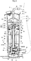
Fig. 1 is a longitudinal sectional view showing a hermetic two-stage compressor according to a first embodiment of the present invention. -
Fig. 2 shows the hermetic two-stage compressor according to the first embodiment of the present invention and is a longitudinal sectional view at a sectional position from the sectional position ofFig. 1 in a circumferential direction. -
Fig. 3 is a view showing a bearing casing and an inflow restricting plate of the hermetic two-stage compressor according to the first embodiment of the present invention and shows a cross section taken along line I-I ofFig. 1 . -
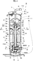
Fig. 4 is a longitudinal sectional view showing a hermetic two-stage compressor according to a second embodiment of the present invention. -
Fig. 5 is a view showing a bearing casing and an inflow restricting plate of the hermetic two-stage compressor according to the second embodiment of the present invention and shows a cross section taken along line IV-IV ofFig. 4 . -
Fig. 6 is a view showing a bearing casing and an inflow restricting plate of a hermetic two-stage compressor according to a modification example of the embodiment of the present invention. - Hereinafter, a hermetic two-stage compressor 1 (hereinafter, referred to as a two-stage compressor 1) according to a first embodiment of the present invention will be described.
- As shown in
Figs. 1 and2 , for example, the two-stage compressor 1 compresses a refrigerant R which is a gas such as carbon dioxide. The two-stage compressor 1 includes ahousing 11, a rotary compressor (low stage-side compression section) 12, a scroll compressor (high stage-side compression section) 13, anelectric motor 14, arotary shaft 15, and abearing device 30 which are provided inside thehousing 11, and aninflow restricting plate 61 which is fixed to thebearing device 30. - The
housing 11 includes amain body portion 21 which is formed in a cylindrical shape, and anupper cover portion 22 and alower cover portion 23 which close an upper opening and a lower opening of themain body portion 21. In addition, a space inside thehousing 11 is sealed. - The
rotary shaft 15 is disposed to extend vertically inside thehousing 11. - The
electric motor 14 is disposed on an outer peripheral side of therotary shaft 15 and rotates therotary shaft 15 around an axis X. That is, theelectric motor 14 includes arotor 38 which is fixed to an outer peripheral surface of therotary shaft 15, and astator 39 which radially faces therotor 38 with a gap between thestator 39 and the outer peripheral surface of therotor 38 and is fixed to an inner surface of themain body portion 21 of thehousing 11. - The
electric motor 14 is connected to a power source (not shown) via awire 14a and rotates therotary shaft 15 by power from the power source. A portion of thestator 39 in a circumferential direction is fixed to the inner surface of thehousing 11, and in portions other than the portion fixed to the inner surface of thehousing 11, the inner surface of thehousing 11 and thestator 39 are disposed with a gap S in a radial direction. - The
rotary compressor 12 is disposed at a position adjacent to thelower cover portion 23 at a lower portion which is one in a direction of the axis X of theelectric motor 14 inside thehousing 11. Therotary compressor 12 includes aneccentric shaft portion 41 which is provided on therotary shaft 15, apiston rotor 42 which is fixed to theeccentric shaft portion 41 and is eccentrically rotated about the axis X according to a rotation of therotary shaft 15, and acylinder 44 which includes a compression chamber C1 accommodating thepiston rotor 42 is formed inside thecylinder 44. - A
suction hole 44a through which the refrigerant R can flow into thecylinder 44 is formed in thecylinder 44. Asuction pipe 33 which is provided to penetrate themain body portion 21 of thehousing 11 is connected to thesuction hole 44a and the refrigerant R is supplied through thesuction pipe 33 from the outside of thehousing 11. In addition, a discharge hole (not shown) is formed in thecylinder 44, and the refrigerant R compressed by therotary compressor 12 is discharged from the discharge hole to a region in thehousing 11 in which theelectric motor 14 is provided. - In addition, oil A is stored in the bottom portion of the
housing 11 and an oil storage O1 is provided in the bottom portion. When the oil A is initially sealed, a liquid surface of the oil storage O1 is positioned above therotary compressor 12. Accordingly, therotary compressor 12 is driven in the oil storage O1. - The
scroll compressor 13 is disposed above theelectric motor 14 inside thehousing 11. Thescroll compressor 13 includes a fixedscroll 51 which is fixed to anupper bearing 31 and anorbiting scroll 57 which is disposed to face the fixedscroll 51 below the fixedscroll 51. - The fixed
scroll 51 includes anend plate 52 which is fixed to an upper surface of theupper bearing 31 and afixed lap 53 which protrudes downward from theend plate 52. Adischarge hole 52a which vertically penetrates theend plate 52 is formed at a center portion (in the vicinity of the axis X) of theend plate 52. - The orbiting
scroll 57 includes anend plate 58 which is disposed to be interposed between the bearing device 30 (upper bearing 31 described below) and theend plate 52 of the fixedscroll 51 in the direction of the axis X and is fixed to therotary shaft 15, and anorbiting lap 59 which protrudes upward from theend plate 58. - The
end plate 58 is fixed to aneccentric shaft portion 56 provided on an upper end of therotary shaft 15 and is eccentrically rotated about the axis X according to the rotation of therotary shaft 15. - The orbiting
lap 59 meshes with the fixedlap 53, and thus, a compression chamber C2 in which the refrigerant R is compressed is formed between the orbitinglap 59 and the fixedlap 53. - Here, a suction hole (not shown) is formed in the fixed
scroll 51, and the refrigerant R which is compressed by therotary compressor 12 and is discharged into thehousing 11 can be sucked into the compression chamber C2 via thebearing device 30 through the suction hole. The refrigerant R compressed in the compression chamber C2 is discharged to the outside of thehousing 11 from adischarge pipe 34 through thedischarge hole 52a of the fixedscroll 51, and thedischarge pipe 34 is open to a space surrounded by the fixedscroll 51 fixed to the upper portion of the fixedscroll 51 in thehousing 11 and thedischarge cover 50 and is provided to penetrate thehousing 11 so as to extend the outside of thehousing 11. - The bearing
device 30 includes theupper bearing 31 which is provided on the upper portion of thehousing 11 inside thehousing 11, andlower bearings housing 11 inside thehousing 11. - The
lower bearings rotary shaft 15 with respect to thehousing 11 at the lower portion of thehousing 11. Specifically, therotary compressor 12 is vertically disposed in the direction of the axis X between thelower bearings lower bearings cylinder 44 by abolt 48. - The
upper bearing 31 includes abearing 31a which rotatably supports therotary shaft 15 around the axis X of therotary shaft 15 with respect to thehousing 11 and a bearingcasing 31b which supports thebearing 31a on thehousing 11 integrally with thebearing 31a. - As shown in
Figs. 1 to 3 , a plurality of suction channels FC are provided in the bearingcasing 31b, and the suction channels FC extend to be parallel to the axis X over the entire region of the bearingcasing 31b in the direction of the axis X with intervals to each other in the circumferential direction. In the present embodiment, each of the suction channels FC is a recessed groove having a rectangular cross section which is recessed from the outer peripheral surface of the bearingcasing 31b toward the radially inner side. - In addition, a suction opening FCa is provided in the bearing
casing 31b, and the suction opening FCa extends from a lower end of the suction channel FC toward the radially inner side so as to be continued to the lower side which is one side (first end side) of the axis X and is open in a fan shape downward when the bearingcasing 31b is viewed. - In addition, a recessed portion (accommodation portion) 31c is provided in the bearing
casing 31b, and the recessedportion 31c is recessed over the entire region in the direction of the axis X from the outer peripheral surface toward the radially inner side at a position at which the recessed portion does not interfere with the suction opening FCa. Thewire 14a of theelectric motor 14 is disposed inside the recessed portion. Aseal member 65 is provided in a gap among the recessedportion 31c, thewire 14a, and the inner surface of thehousing 11. For example, as theseal member 65, a seal material such as a resin can be used. - In addition, a bearing
channel 31d (refer toFig. 2 ) is formed in the bearingcasing 31b, and thebearing channel 31d radially penetrates the bearingcasing 31b and is open to the inside of thehousing 11 at a position in the direction of the axis X at which theorbiting scroll 57 is fixed to theeccentric shaft portion 56. - In addition, an oil return pipe (oil return section) 72 is provided in the bearing
casing 31b, and, at a position at which theoil return pipe 72 does not interfere with the suction opening FCa and the recessedportion 31c and a position of an end portion on the radially outer side, theoil return pipe 72 communicates with the bearingchannel 31d, penetrates the bearingcasing 31b toward theelectric motor 14 to extend along the inner surface of thehousing 11, and protrudes downward from the bearingcasing 31b. - As shown in
Fig. 3 , theinflow restricting plate 61 is fixed to the bearingcasing 31b bybolts 60 from below. Theinflow restricting plate 61 is formed in an annular shape about the axis X. Theinflow restricting plate 61 includes a plurality ofnotches 63, which are cut out from the end portion on the radially inner side toward the radially inner side, at positions corresponding to the suction openings FCa. A lower surface of theinflow restricting plate 61 becomes a restrictingsurface 62, and a bottom portion of eachnotch 63 forms aninner edge portion 62a of the restrictingsurface 62. Theinner edge portion 62a has a curved shape formed along the circumferential direction. Theinner edge portion 62a is positioned at a radially intermediate position of the suction opening FCa, and as a result, only the radially inner position of the suction opening FCa is open toward theelectric motor 14 by theinflow restricting plate 61. Accordingly, a flow of the refrigerant R to the suction opening FCa on the radially outer side is restricted by the restrictingsurface 62. - In addition, a
notch 61a is provided in theinflow restricting plate 61, and thenotch 61a is recessed from theouter edge portion 62b toward the radially inner side at a position corresponding to the position of thewire 14a so as not to interfere with thewire 14a. - As shown in
Fig. 1 , when viewed from a cross section including the axis X, the restrictingsurface 62 is provided to protrude from the inner surface of thehousing 11 toward the radially inner side. - In addition, in the present embodiment, a
seal member 66 is provided in a gap between the inner surface of thehousing 11 and anouter edge portion 62b (an end edge on the radially outer side along the inner surface of the housing 11) of the restrictingsurface 62. As theseal member 66, a seal member formed of a resin, an O ring, or the like can be used. - In the two-stage compressor 1 of the above-described present embodiment, the oil A of the oil storage O1 and the refrigerant R are compressed by the
rotary compressor 12. Accordingly, the oil A is included in the refrigerant R discharged from therotary compressor 12. A portion of the refrigerant R including the oil A flows out toward theelectric motor 14, and thereafter, flows toward thescroll compressor 13 through the gap between thestator 39 and therotor 38 or the through-hole 37 provided in therotor 38. In addition, when the refrigerant R passes through theelectric motor 14, the oil A in the refrigerant R comes into contact with therotor 38 or anoil separation plate 38a which is provided on therotor 38 and extends in the radial direction, and thus, a content of the oil A in the refrigerant R decreases. - Meanwhile, the refrigerant R which has passed through the gap S between the
stator 39 and thehousing 11 does not come into contact with therotor 38 and flows toward thescroll compressor 13 as it is. Accordingly, the refrigerant R flows toward thescroll compressor 13 in a state where the content of the oil A in the refrigerant R is high. That is, the amount of the oil A in the refrigerant R discharged from therotary compressor 12 decreases on the radially inner side of thehousing 11 and increases on the radially outer side thereof. - Here, in the present embodiment, the
inflow restricting plate 61 having the restrictingsurface 62 is provided in the bearingcasing 31b, and thus, the flow of the refrigerant R to the suction opening FCa on the radially outer side can be restricted. Accordingly, it is possible to prevent the refrigerant R having a high content of oil A on the radially outer side flows into the suction channel FC through the suction opening FCa as it is. In addition, the refrigerant R on the radially inner side having a low content of oil A can flow into the suction channel FC through the suction opening FCa. - As a result, it is possible to supply the refrigerant R having a low content of oil A to the
scroll compressor 13, and it is possible to decrease the amount of the oil A in the refrigerant R which is compressed by thescroll compressor 13 and is discharged therefrom. It is possible to decrease an oil circulation amount (OC%) in a system including the two-stage compressor 1. - In addition, if the refrigerant R on the radially outer side comes into contact with the restricting
surface 62, the oil A in the refrigerant R is attached to the restrictingsurface 62, and the refrigerant R in which the content of the oil A has decreased is guided to the radially inner side by the restrictingsurface 62 and flows from suction opening FCa into suction channel FC. Accordingly, in a state where the amount of the oil A in the refrigerant R is decreased by the restrictingsurface 62, the refrigerant R is supplied from the suction channel FC to thescroll compressor 13. In this way, it is possible to decrease the amount of the oil A in the refrigerant R which is compressed by thescroll compressor 13 and is discharged from thedischarge pipe 34 to the outside of thehousing 11, and it is possible to decrease the oil circulation amount (OC%) in the system. - In addition, the
inflow restricting plate 61 is provided in the bearingcasing 31b, and thus, the restrictingsurface 62 can be provided in the bearingcasing 31b. Accordingly, compared to a case where a member corresponding to theinflow restricting plate 61 is attached to thehousing 11, a welding work or the like with respect to thehousing 11 is not required, and it is possible to very easily provide the restrictingsurface 62 in the bearingcasing 31b. Accordingly, it is possible to effectively separate the oil A in the refrigerant R from the refrigerant R while easily manufacturing the two-stage compressor 1 having the restrictingsurface 62. - In addition, the
oil return pipe 72 is provided, and thus, the oil which is used to lubricate the high stage-side compression section is returned into thehousing 11 through theoil return pipe 72. Accordingly, it is possible to further decrease the amount of the oil A in the refrigerant R which is compressed by thescroll compressor 13 and is discharged therefrom. In addition, theoil return pipe 72 is provided on the end portion on the radially outer side of the bearingcasing 31b, and thus, theoil return pipe 72 is provided at a position separated from the opening portion on the radially inner side in the suction opening FCa on the radially inner side. Therefore, the oil A which is returned from theoil return pipe 72 to thehousing 11 can be prevented from flowing from the suction opening FCa into the suction channel FC as it is. Accordingly, it is possible to further decrease the amount of the oil A in the refrigerant R which is compressed by thescroll compressor 13 and is discharged therefrom. - In addition, the refrigerant R having a high content of oil A which has passed through the gap S between the
housing 11 and thestator 39 in the region on the radially outer side inside thehousing 11 can be prevented from flowing from the portion between the restrictingsurface 62 and the inner surface of thehousing 11 into thescroll compressor 13 as it is by theseal member 66. Therefore, it is possible to further decrease the amount of the oil A in the refrigerant R which is compressed by thescroll compressor 13 and is discharged therefrom. - In addition, even when the recessed
portion 31c into which thewire 14a of theelectric motor 14 is inserted is formed in the bearingcasing 31b, it is possible to seal the gap among the recessedportion 31c, thewire 14a, and the inner surface of thehousing 11 by theseal member 65. Accordingly, it is possible to prevent the refrigerant R including the oil A from being supplied to thescroll compressor 13 through the gap as it is. - Next, a two-
stage compressor 80 according to a second embodiment of the present invention will be described with reference toFigs. 4 and5 . InFig. 4 , for convenience of descriptions, thewire 14a of theelectric motor 14 and theoil return pipe 72 are not shown. - The same reference numerals are assigned to the components similar to those of the second embodiment, and detail descriptions.
- In the two-
stage compressor 80 of the present embodiment, aninflow restricting plate 81 having a restrictingsurface 82 is different from theinflow restricting plate 61 of the first embodiment. - The
inflow restricting plate 81 includes anannular portion 83 which is disposed on the radially outer side along the inner surface of thehousing 11 and is formed in an annular shape about the axis X, and aconical portion 84 which is continuous to the radially inner side of theannular portion 83 so as to be provided integrally with theannular portion 83. - A lower surface of the
annular portion 83 is aflat surface 86 which is formed in an annular shape about the axis X. In addition, an outer surface of theconical portion 84 is aninclined surface 87 which is formed in a truncated conical shape about the axis X. Theinclined surface 87 is inclined downward from theflat surface 86 toward the radially inner side. - In this way, the restricting
surface 82 of the present embodiment includes theflat surface 86 and theinclined surface 87. Aninner edge portion 87a which is an end edge on the radially inner side of theinclined surface 87 is positioned on the radially inner side from thestator 39 and on the radially outer side from the bearingcasing 31b and therotary shaft 15. - In addition, in the present embodiment, the
inner edge portion 87a of theinflow restricting plate 81 is disposed at a position at which an intake amount of the refrigerant R required in thescroll compressor 13 can be secured, that is, an opening area of the suction opening FCa can be secured. - In the two-
stage compressor 80 of the above-described present embodiment, the restrictingsurface 82 has theinclined surface 87, and thus, it is possible to form an opening portion OP which is formed in an annular shape about the axis X so as to extend downward in the direction of the axis X from the suction opening FCa. Accordingly, compared to the first embodiment, the area of the suction opening FCa which is open toward theelectric motor 14 can increase. Therefore, it is possible to secure a flow rate of the refrigerant R flowing from the inside of thehousing 11 into the suction channel FC. - In addition, the refrigerant R having a high content of the oil A in the radially outer side region in the
housing 11 flows to the radially inner side along theflat surface 86, and thereafter, collides with theinclined surface 87, and thus, the oil A can be attached to theinclined surface 87. Accordingly, the refrigerant R can flow into the suction channel FC in a state where the content of the oil A in the refrigerant R further decreases so as to be supplied to thescroll compressor 13. As a result, it is possible to further decrease the amount of the oil A in the refrigerant R which is compressed by thescroll compressor 13 and is discharged to the outside of thehousing 11 and it is possible to further decrease the oil circulation amount (OC%) in the system including the two-stage compressor 80. - In addition, in the present embodiment, the
inner edge portion 87a on the radially inner side of theinclined surface 87 is positioned on the radially inner side from thestator 39, and thus, the restrictingsurface 82 extends to the position of therotor 38. Accordingly, the refrigerant R flowing through the radially inner side in thehousing 11 and the oil A in the refrigerant R come into contact with therotor 38, and the refrigerant R in which the amount of the oil A is sufficiently decreased by therotor 38 can flow from the suction opening FCa into the suction channel FC. - In addition, the
inner edge portion 87a of theinflow restricting plate 81 is disposed at the position at which the intake amount of the refrigerant R required in thescroll compressor 13 can be secured, and thus, it is possible to prevent compression efficiency in thescroll compressor 13 from decreasing. - Hereinbefore, the embodiments of the present invention are described in detail with reference to the drawings. However, the respective configurations and combinations thereof in the respective embodiments are merely examples, and additions, omissions, substations, and other modifications of configurations are possible within the scope which does not depart from the present invention. In addition, the present invention is not limited to the embodiments and are limited by only claims.
- For example, the bearing
casing 31b and each of theinflow restricting plates surfaces casing 31b. - In addition, similarly to the second embodiment, in the first embodiment, the
inner edge portion 62a of the restrictingsurface 62 may be disposed on the radially inner side from thestator 39. In addition, in this case, the position of theinner edge portion 62a may be determined such that the intake amount of the refrigerant R required in thescroll compressor 13 can be secured. - In addition, in the bearing
casing 31b, instead of the recessedportion 31c, a through-hole penetrating the bearingcasing 31b in the direction of the axis X may be formed such that thewire 14a is inserted into the through-hole so as to be disposed. - In addition, as shown in
Fig. 6 , an annular recessedportion 90 which is recessed upward and is formed in an annular shape about the axis X may be provided in the restrictingsurface 62A. According to the annular recessed portion, the refrigerant R on the radially outer side comes into contact with the restrictingsurface 62A, and thus, the oil A attached to the restrictingsurface 62A flows toward the radially inner side, and it is possible to prevent the oil A from being sucked into the suction opening FCa. The annular recessedportion 90 can be provided in any one of the restrictingsurface 62 of the first embodiment and the restrictingsurface 82 of the second embodiment. - In addition, in the
housing 11, therotary compressor 12 is provided as the low stage-side compressor and thescroll compressor 13 is provided as the high stage-side compressor. However, the present invention is not limited to this. For example, thescroll compressor 13 may be provided as the low stage-side compressor and therotary compressor 12 may be used as the high stage-side compressor. In addition, thescroll compressor 13 may be provided on both the low stage side and the high stage side, or therotary compressor 12 may be provided on both the low stage side and the high stage side. In addition, a compressor other than thescroll compressor 13 and therotary compressor 12 may be provided. - Moreover, the restricting
surfaces - According to the hermetic two-stage compressor, the hermetic two-stage compressor can be easily manufactured, and the oil in the gas can be effectively separated. Reference Signs List
-
- 1, 80: hermetic two-stage compressor
- 11: housing
- 12: rotary compressor (low stage-side compression section)
- 13: scroll compressor (high stage-side compression section)
- 14: electric motor
- 14a: wire
- 15: rotary shaft
- 21: main body portion
- 22: upper cover portion
- 23: lower cover portion
- 30: bearing device
- 31: upper bearing
- 31a: bearing
- 31b: bearing casing
- 31c: recessed portion (accommodation portion)
- 31d: bearing channel
- 32A, 32B: lower bearing
- 33: suction pipe
- 34: discharge pipe
- 37: through-hole
- 38: rotor
- 38a: oil separation plate
- 39: stator
- 41: eccentric shaft portion
- 42: piston rotor
- 44: cylinder
- 44a: suction hole
- 48: bolt
- 50: discharge cover
- 51: fixed scroll
- 52: end plate
- 52a: discharge hole
- 53: fixed lap
- 56: eccentric shaft portion
- 57: orbiting scroll
- 58: end plate
- 59: orbiting lap
- 60: bolt
- 61: inflow restricting plate
- 61a: notch
- 62, 62A: restricting surface
- 62a: inner edge portion
- 62b: outer edge portion
- 63: notch
- 65: seal member
- 66: seal member
- 72: oil return pipe (oil return section)
- 81: inflow restricting plate
- 82: restricting surface
- 83: annular portion
- 84: conical portion
- 86: flat surface
- 87: inclined surface
- 87a: inner edge portion
- 90: annular recessed portion
- C1: compression chamber
- C2: compression chamber
- O1: oil storage
- R: refrigerant
- X: axis
- A: oil
- S: gap
- FC: suction channel
- FCa: suction opening
- OP: opening portion
Claims (6)
- A hermetic two-stage compressor (1, 80) comprising:a housing (11) which includes an oil storage (O1) inside the housing (11);a rotary shaft (15) which is disposed in the housing (11) ;a motor (14) which is disposed in the housing (11) so as to rotate the rotary shaft (15) and includes a stator (39) which is provided on a radially outer side and a rotor (39) which is provided on a radially inner side;a low stage-side compression section (12) which is disposed on one side in an axial direction of the rotary shaft (15) with respect to the motor (14) in the housing (11) and is connected to the rotary shaft (15) so as to compress a gas;a bearing device (30) which is disposed on the other side in the axial direction with respect to the motor (14) in the housing (11) and includes a bearing (31a) which supports the rotary shaft (15) and a bearing casing (31b) which supports the bearing (31a) to the housing (11); anda high stage-side compression section (13) which is disposed furhter on the other side in the axial direction with respect to the bearing device (30) and further compresses the gas discharged from the low stage-side compression section (12),characterised in that the bearing casing (31b) includesa plurality of suction channels (FC) which are provided to suck the gas into the high stage-side compression section (13) and each of the plurality of the suction channels (FC) include a suction opening (FCa) which is open to the one side in the axial direction, anda restricting surface (62) which is disposed between the suction opening (FCa) and the motor (14) and is provided toward the radially inner side from an inner surface of the housing (11) so as to restrict a flow of the gas to the suction opening (FCa) on the radially outer side, whereinthe plurality of suction channels (FC) extend to be parallel to the axis (X) over the entire region of the bearing casing (31b) in the direction of the axis (X) with intervals to each other in the circumferential direction (X), andwherein the restricting surface (62) includes a plurality of notches (63) which are cut out from an end portion on the radially inner side toward the radially inner side at a position corresponding to the suction opening (FCa) and only a position on the radially inner side of the suction opening (FCa) is open toward the motor (14) .
- The hermetic two-stage compressor (1) according to claim 1, further comprising:
an inflow restricting plate (61) which is fixed to the bearing casing (31b), is formed in a plate shape, and includes the restricting surface (62) on the one side of the axial direction. - A hermetic two-stage compressor (80) according to any one of claims 1 or 2,
wherein an inner edge portion (87a) on the radially inner side of the restricting surface (82) is disposed at a position on the radially inner side of the stator (39), and
wherein the restricting surface (82) closes a portion of the suction opening (FCa) so as to secure an intake amount of the gas required in the high stage-side compression section (13). - The hermetic two-stage compressor (1, 80) according to any one of claims 1 to 3, further comprising:
a seal member (66) which is provided in a gap between an outer edge portion (62b) on the radially outer side of the restricting surface and the inner surface of the housing (11). - The hermetic two-stage compressor (1, 80) according to any one of claims 1 to 4, further comprising:
an oil return section (72) which is provided at a position of an end portion on the radially outer side in the bearing casing (31b), and causes the high stage-side compression section (13) and the one side in the axial direction from the bearing casing (31b) in the housing (11) to communicate with each other such that oil from the high stage-side compression section (13) can flow through the oil return section (72). - A hermetic two-stage compressor (80) comprising:a housing (11) which includes an oil storage (O1) inside the housing (11);a rotary shaft (15) which is disposed in the housing (11) ;a motor (14) which is disposed in the housing (11) so as to rotate the rotary shaft (15) and includes a stator (39) which is provided on a radially outer side and a rotor (39) which is provided on a radially inner side;a low stage-side compression section (12) which is disposed on one side in an axial direction of the rotary shaft (15) with respect to the motor (14) in the housing (11) and is connected to the rotary shaft (15) so as to compress a gas;a bearing device (30) which is disposed on the other side in the axial direction with respect to the motor (14) in the housing (11) and includes a bearing (31a) which supports the rotary shaft (15) and a bearing casing (31b) which supports the bearing (31a) to the housing (11); anda high stage-side compression section (13) which is disposed further on the other side in the axial direction with respect to the bearing device (30) and further compresses the gas discharged from the low stage-side compression section (12),characterised in that the bearing casing (31b) includesa plurality of suction channels (FC) which are provided to suck the gas into the high stage-side compression section (13) and each of the plurality of suction channels (FC) include a suction opening (FCa) which is open to the one side in the axial direction, anda restricting surface (82) which is disposed between the suction opening (FCa) and the motor (14) and is provided toward the radially inner side from an inner surface of the housing (11) so as to restrict a flow of the gas to the suction opening (FCa) on the radially outer side,wherein the plurality of suction channels (FC) extend to be parallel to the axis (X) over the entire region of the bearing casing (31b) in the direction of the axis (X) with intervals to each other in the circumferential direction (X), andwherein the restricting surface (82) includesa flat surface (86) which is provided on an end portion on the radially outer side which is an inner surface side of the housing and is perpendicular to the axis to be formed in an annular shape about the axis, andan inclined surface (87) which is inclined toward the one side in the axial direction from the flat surface (86) toward the radially inner side so as to be formed in a truncated conical shape about the axis.
Applications Claiming Priority (2)
| Application Number | Priority Date | Filing Date | Title |
|---|---|---|---|
| JP2016081000A JP6755114B2 (en) | 2016-04-14 | 2016-04-14 | Sealed two-stage compressor |
| PCT/JP2017/015333 WO2017179714A1 (en) | 2016-04-14 | 2017-04-14 | Hermetic two-stage compressor |
Publications (3)
| Publication Number | Publication Date |
|---|---|
| EP3409948A1 EP3409948A1 (en) | 2018-12-05 |
| EP3409948A4 EP3409948A4 (en) | 2019-03-06 |
| EP3409948B1 true EP3409948B1 (en) | 2020-05-13 |
Family
ID=60041837
Family Applications (1)
| Application Number | Title | Priority Date | Filing Date |
|---|---|---|---|
| EP17782527.0A Active EP3409948B1 (en) | 2016-04-14 | 2017-04-14 | Hermetic two-stage compressor |
Country Status (6)
| Country | Link |
|---|---|
| EP (1) | EP3409948B1 (en) |
| JP (1) | JP6755114B2 (en) |
| KR (1) | KR102061440B1 (en) |
| CN (1) | CN108700076B (en) |
| AU (1) | AU2017251203B2 (en) |
| WO (1) | WO2017179714A1 (en) |
Families Citing this family (2)
| Publication number | Priority date | Publication date | Assignee | Title |
|---|---|---|---|---|
| JP2023076188A (en) | 2021-11-22 | 2023-06-01 | 三菱重工サーマルシステムズ株式会社 | compressor |
| JP2023076187A (en) | 2021-11-22 | 2023-06-01 | 三菱重工サーマルシステムズ株式会社 | compressor |
Family Cites Families (7)
| Publication number | Priority date | Publication date | Assignee | Title |
|---|---|---|---|---|
| US7044717B2 (en) * | 2002-06-11 | 2006-05-16 | Tecumseh Products Company | Lubrication of a hermetic carbon dioxide compressor |
| JP2009047039A (en) * | 2007-08-17 | 2009-03-05 | Mitsubishi Heavy Ind Ltd | Multistage compressor |
| US20090148328A1 (en) * | 2007-12-06 | 2009-06-11 | Chung-Hung Yeh | Lubricant backflow structure of compressor |
| JP5444850B2 (en) * | 2009-05-27 | 2014-03-19 | ダイキン工業株式会社 | Compressor |
| JP5709544B2 (en) * | 2011-01-17 | 2015-04-30 | 三菱重工業株式会社 | Compressor |
| JP2012202252A (en) * | 2011-03-24 | 2012-10-22 | Sanyo Electric Co Ltd | Scroll compression device |
| WO2013015215A1 (en) * | 2011-07-22 | 2013-01-31 | 三菱重工業株式会社 | Fluid machine |
-
2016
- 2016-04-14 JP JP2016081000A patent/JP6755114B2/en active Active
-
2017
- 2017-04-14 KR KR1020187025155A patent/KR102061440B1/en active IP Right Grant
- 2017-04-14 CN CN201780010683.0A patent/CN108700076B/en active Active
- 2017-04-14 EP EP17782527.0A patent/EP3409948B1/en active Active
- 2017-04-14 WO PCT/JP2017/015333 patent/WO2017179714A1/en active Application Filing
- 2017-04-14 AU AU2017251203A patent/AU2017251203B2/en active Active
Non-Patent Citations (1)
| Title |
|---|
| None * |
Also Published As
| Publication number | Publication date |
|---|---|
| CN108700076A (en) | 2018-10-23 |
| AU2017251203B2 (en) | 2019-06-20 |
| AU2017251203A1 (en) | 2018-08-30 |
| CN108700076B (en) | 2020-07-14 |
| EP3409948A1 (en) | 2018-12-05 |
| JP6755114B2 (en) | 2020-09-16 |
| KR20180107215A (en) | 2018-10-01 |
| EP3409948A4 (en) | 2019-03-06 |
| KR102061440B1 (en) | 2019-12-31 |
| JP2017190732A (en) | 2017-10-19 |
| WO2017179714A1 (en) | 2017-10-19 |
Similar Documents
| Publication | Publication Date | Title |
|---|---|---|
| US10890186B2 (en) | Compressor | |
| EP3916232A1 (en) | Co-rotating compressor | |
| US9651047B2 (en) | Compressor having a partitioned discharge chamber | |
| US10273957B2 (en) | Two-cylinder hermetic compressor | |
| EP3409948B1 (en) | Hermetic two-stage compressor | |
| US20200003199A1 (en) | Compressor | |
| US10436199B2 (en) | Rotary compressor | |
| WO2014206334A1 (en) | Scroll compressor with oil management system | |
| KR20150076074A (en) | Sealed compressor | |
| US10539139B2 (en) | Compressor | |
| US10519954B2 (en) | Compressor with oil management system | |
| JP2009114943A (en) | Scroll fluid machine | |
| EP3575605B1 (en) | Hermetic compressor | |
| US10294943B2 (en) | Scroll compressor with a lubrication arrangement | |
| US9581161B2 (en) | Compressor with service valve assembly | |
| JP2019190468A (en) | Scroll compressor | |
| JP6596233B2 (en) | Hermetic scroll compressor | |
| EP3992461B1 (en) | Scroll compressor | |
| CN110603381B (en) | Scroll compressor having a discharge port | |
| JP4359164B2 (en) | 2-stage rotary compressor | |
| EP3447295A1 (en) | Open-type compressor | |
| JP2023076187A (en) | compressor | |
| JP2006070711A (en) | Scroll compressor | |
| JPH0633888A (en) | Horizontal rotary compressor |
Legal Events
| Date | Code | Title | Description |
|---|---|---|---|
| STAA | Information on the status of an ep patent application or granted ep patent |
Free format text: STATUS: THE INTERNATIONAL PUBLICATION HAS BEEN MADE |
|
| PUAI | Public reference made under article 153(3) epc to a published international application that has entered the european phase |
Free format text: ORIGINAL CODE: 0009012 |
|
| STAA | Information on the status of an ep patent application or granted ep patent |
Free format text: STATUS: REQUEST FOR EXAMINATION WAS MADE |
|
| 17P | Request for examination filed |
Effective date: 20180831 |
|
| AK | Designated contracting states |
Kind code of ref document: A1 Designated state(s): AL AT BE BG CH CY CZ DE DK EE ES FI FR GB GR HR HU IE IS IT LI LT LU LV MC MK MT NL NO PL PT RO RS SE SI SK SM TR |
|
| AX | Request for extension of the european patent |
Extension state: BA ME |
|
| A4 | Supplementary search report drawn up and despatched |
Effective date: 20190131 |
|
| RIC1 | Information provided on ipc code assigned before grant |
Ipc: F04C 18/02 20060101ALI20190125BHEP Ipc: F04C 29/12 20060101ALI20190125BHEP Ipc: F04C 29/00 20060101AFI20190125BHEP Ipc: F04C 29/02 20060101ALI20190125BHEP Ipc: F04C 18/356 20060101ALN20190125BHEP Ipc: F04C 23/00 20060101ALI20190125BHEP |
|
| DAV | Request for validation of the european patent (deleted) | ||
| DAX | Request for extension of the european patent (deleted) | ||
| GRAP | Despatch of communication of intention to grant a patent |
Free format text: ORIGINAL CODE: EPIDOSNIGR1 |
|
| STAA | Information on the status of an ep patent application or granted ep patent |
Free format text: STATUS: GRANT OF PATENT IS INTENDED |
|
| RIC1 | Information provided on ipc code assigned before grant |
Ipc: F04C 29/02 20060101ALI20191016BHEP Ipc: F04C 18/02 20060101ALI20191016BHEP Ipc: F04C 29/12 20060101ALI20191016BHEP Ipc: F04C 18/356 20060101ALN20191016BHEP Ipc: F04C 23/00 20060101ALI20191016BHEP Ipc: F04C 29/00 20060101AFI20191016BHEP |
|
| INTG | Intention to grant announced |
Effective date: 20191108 |
|
| RIC1 | Information provided on ipc code assigned before grant |
Ipc: F04C 18/02 20060101ALI20191029BHEP Ipc: F04C 29/00 20060101AFI20191029BHEP Ipc: F04C 23/00 20060101ALI20191029BHEP Ipc: F04C 18/356 20060101ALN20191029BHEP Ipc: F04C 29/12 20060101ALI20191029BHEP Ipc: F04C 29/02 20060101ALI20191029BHEP |
|
| GRAS | Grant fee paid |
Free format text: ORIGINAL CODE: EPIDOSNIGR3 |
|
| GRAA | (expected) grant |
Free format text: ORIGINAL CODE: 0009210 |
|
| STAA | Information on the status of an ep patent application or granted ep patent |
Free format text: STATUS: THE PATENT HAS BEEN GRANTED |
|
| AK | Designated contracting states |
Kind code of ref document: B1 Designated state(s): AL AT BE BG CH CY CZ DE DK EE ES FI FR GB GR HR HU IE IS IT LI LT LU LV MC MK MT NL NO PL PT RO RS SE SI SK SM TR |
|
| REG | Reference to a national code |
Ref country code: GB Ref legal event code: FG4D |
|
| REG | Reference to a national code |
Ref country code: CH Ref legal event code: EP |
|
| REG | Reference to a national code |
Ref country code: DE Ref legal event code: R096 Ref document number: 602017016788 Country of ref document: DE |
|
| REG | Reference to a national code |
Ref country code: AT Ref legal event code: REF Ref document number: 1270654 Country of ref document: AT Kind code of ref document: T Effective date: 20200615 |
|
| REG | Reference to a national code |
Ref country code: LT Ref legal event code: MG4D |
|
| REG | Reference to a national code |
Ref country code: NL Ref legal event code: MP Effective date: 20200513 |
|
| PG25 | Lapsed in a contracting state [announced via postgrant information from national office to epo] |
Ref country code: IS Free format text: LAPSE BECAUSE OF FAILURE TO SUBMIT A TRANSLATION OF THE DESCRIPTION OR TO PAY THE FEE WITHIN THE PRESCRIBED TIME-LIMIT Effective date: 20200913 Ref country code: PT Free format text: LAPSE BECAUSE OF FAILURE TO SUBMIT A TRANSLATION OF THE DESCRIPTION OR TO PAY THE FEE WITHIN THE PRESCRIBED TIME-LIMIT Effective date: 20200914 Ref country code: GR Free format text: LAPSE BECAUSE OF FAILURE TO SUBMIT A TRANSLATION OF THE DESCRIPTION OR TO PAY THE FEE WITHIN THE PRESCRIBED TIME-LIMIT Effective date: 20200814 Ref country code: NO Free format text: LAPSE BECAUSE OF FAILURE TO SUBMIT A TRANSLATION OF THE DESCRIPTION OR TO PAY THE FEE WITHIN THE PRESCRIBED TIME-LIMIT Effective date: 20200813 Ref country code: FI Free format text: LAPSE BECAUSE OF FAILURE TO SUBMIT A TRANSLATION OF THE DESCRIPTION OR TO PAY THE FEE WITHIN THE PRESCRIBED TIME-LIMIT Effective date: 20200513 Ref country code: SE Free format text: LAPSE BECAUSE OF FAILURE TO SUBMIT A TRANSLATION OF THE DESCRIPTION OR TO PAY THE FEE WITHIN THE PRESCRIBED TIME-LIMIT Effective date: 20200513 Ref country code: LT Free format text: LAPSE BECAUSE OF FAILURE TO SUBMIT A TRANSLATION OF THE DESCRIPTION OR TO PAY THE FEE WITHIN THE PRESCRIBED TIME-LIMIT Effective date: 20200513 |
|
| PG25 | Lapsed in a contracting state [announced via postgrant information from national office to epo] |
Ref country code: BG Free format text: LAPSE BECAUSE OF FAILURE TO SUBMIT A TRANSLATION OF THE DESCRIPTION OR TO PAY THE FEE WITHIN THE PRESCRIBED TIME-LIMIT Effective date: 20200813 Ref country code: RS Free format text: LAPSE BECAUSE OF FAILURE TO SUBMIT A TRANSLATION OF THE DESCRIPTION OR TO PAY THE FEE WITHIN THE PRESCRIBED TIME-LIMIT Effective date: 20200513 Ref country code: LV Free format text: LAPSE BECAUSE OF FAILURE TO SUBMIT A TRANSLATION OF THE DESCRIPTION OR TO PAY THE FEE WITHIN THE PRESCRIBED TIME-LIMIT Effective date: 20200513 Ref country code: HR Free format text: LAPSE BECAUSE OF FAILURE TO SUBMIT A TRANSLATION OF THE DESCRIPTION OR TO PAY THE FEE WITHIN THE PRESCRIBED TIME-LIMIT Effective date: 20200513 |
|
| REG | Reference to a national code |
Ref country code: AT Ref legal event code: MK05 Ref document number: 1270654 Country of ref document: AT Kind code of ref document: T Effective date: 20200513 |
|
| PG25 | Lapsed in a contracting state [announced via postgrant information from national office to epo] |
Ref country code: NL Free format text: LAPSE BECAUSE OF FAILURE TO SUBMIT A TRANSLATION OF THE DESCRIPTION OR TO PAY THE FEE WITHIN THE PRESCRIBED TIME-LIMIT Effective date: 20200513 Ref country code: AL Free format text: LAPSE BECAUSE OF FAILURE TO SUBMIT A TRANSLATION OF THE DESCRIPTION OR TO PAY THE FEE WITHIN THE PRESCRIBED TIME-LIMIT Effective date: 20200513 |
|
| PG25 | Lapsed in a contracting state [announced via postgrant information from national office to epo] |
Ref country code: DK Free format text: LAPSE BECAUSE OF FAILURE TO SUBMIT A TRANSLATION OF THE DESCRIPTION OR TO PAY THE FEE WITHIN THE PRESCRIBED TIME-LIMIT Effective date: 20200513 Ref country code: AT Free format text: LAPSE BECAUSE OF FAILURE TO SUBMIT A TRANSLATION OF THE DESCRIPTION OR TO PAY THE FEE WITHIN THE PRESCRIBED TIME-LIMIT Effective date: 20200513 Ref country code: EE Free format text: LAPSE BECAUSE OF FAILURE TO SUBMIT A TRANSLATION OF THE DESCRIPTION OR TO PAY THE FEE WITHIN THE PRESCRIBED TIME-LIMIT Effective date: 20200513 Ref country code: SM Free format text: LAPSE BECAUSE OF FAILURE TO SUBMIT A TRANSLATION OF THE DESCRIPTION OR TO PAY THE FEE WITHIN THE PRESCRIBED TIME-LIMIT Effective date: 20200513 Ref country code: CZ Free format text: LAPSE BECAUSE OF FAILURE TO SUBMIT A TRANSLATION OF THE DESCRIPTION OR TO PAY THE FEE WITHIN THE PRESCRIBED TIME-LIMIT Effective date: 20200513 Ref country code: RO Free format text: LAPSE BECAUSE OF FAILURE TO SUBMIT A TRANSLATION OF THE DESCRIPTION OR TO PAY THE FEE WITHIN THE PRESCRIBED TIME-LIMIT Effective date: 20200513 Ref country code: IT Free format text: LAPSE BECAUSE OF FAILURE TO SUBMIT A TRANSLATION OF THE DESCRIPTION OR TO PAY THE FEE WITHIN THE PRESCRIBED TIME-LIMIT Effective date: 20200513 Ref country code: ES Free format text: LAPSE BECAUSE OF FAILURE TO SUBMIT A TRANSLATION OF THE DESCRIPTION OR TO PAY THE FEE WITHIN THE PRESCRIBED TIME-LIMIT Effective date: 20200513 |
|
| REG | Reference to a national code |
Ref country code: DE Ref legal event code: R097 Ref document number: 602017016788 Country of ref document: DE |
|
| PG25 | Lapsed in a contracting state [announced via postgrant information from national office to epo] |
Ref country code: PL Free format text: LAPSE BECAUSE OF FAILURE TO SUBMIT A TRANSLATION OF THE DESCRIPTION OR TO PAY THE FEE WITHIN THE PRESCRIBED TIME-LIMIT Effective date: 20200513 Ref country code: SK Free format text: LAPSE BECAUSE OF FAILURE TO SUBMIT A TRANSLATION OF THE DESCRIPTION OR TO PAY THE FEE WITHIN THE PRESCRIBED TIME-LIMIT Effective date: 20200513 |
|
| PLBE | No opposition filed within time limit |
Free format text: ORIGINAL CODE: 0009261 |
|
| STAA | Information on the status of an ep patent application or granted ep patent |
Free format text: STATUS: NO OPPOSITION FILED WITHIN TIME LIMIT |
|
| 26N | No opposition filed |
Effective date: 20210216 |
|
| PG25 | Lapsed in a contracting state [announced via postgrant information from national office to epo] |
Ref country code: SI Free format text: LAPSE BECAUSE OF FAILURE TO SUBMIT A TRANSLATION OF THE DESCRIPTION OR TO PAY THE FEE WITHIN THE PRESCRIBED TIME-LIMIT Effective date: 20200513 |
|
| PG25 | Lapsed in a contracting state [announced via postgrant information from national office to epo] |
Ref country code: MC Free format text: LAPSE BECAUSE OF FAILURE TO SUBMIT A TRANSLATION OF THE DESCRIPTION OR TO PAY THE FEE WITHIN THE PRESCRIBED TIME-LIMIT Effective date: 20200513 |
|
| PG25 | Lapsed in a contracting state [announced via postgrant information from national office to epo] |
Ref country code: LU Free format text: LAPSE BECAUSE OF NON-PAYMENT OF DUE FEES Effective date: 20210414 |
|
| REG | Reference to a national code |
Ref country code: BE Ref legal event code: MM Effective date: 20210430 |
|
| PG25 | Lapsed in a contracting state [announced via postgrant information from national office to epo] |
Ref country code: LI Free format text: LAPSE BECAUSE OF NON-PAYMENT OF DUE FEES Effective date: 20210430 Ref country code: CH Free format text: LAPSE BECAUSE OF NON-PAYMENT OF DUE FEES Effective date: 20210430 |
|
| PG25 | Lapsed in a contracting state [announced via postgrant information from national office to epo] |
Ref country code: IE Free format text: LAPSE BECAUSE OF NON-PAYMENT OF DUE FEES Effective date: 20210414 |
|
| PG25 | Lapsed in a contracting state [announced via postgrant information from national office to epo] |
Ref country code: BE Free format text: LAPSE BECAUSE OF NON-PAYMENT OF DUE FEES Effective date: 20210430 |
|
| REG | Reference to a national code |
Ref country code: DE Ref legal event code: R082 Ref document number: 602017016788 Country of ref document: DE Representative=s name: CBDL PATENTANWAELTE GBR, DE |
|
| PGFP | Annual fee paid to national office [announced via postgrant information from national office to epo] |
Ref country code: FR Payment date: 20230309 Year of fee payment: 7 |
|
| PGFP | Annual fee paid to national office [announced via postgrant information from national office to epo] |
Ref country code: GB Payment date: 20230302 Year of fee payment: 7 |
|
| PG25 | Lapsed in a contracting state [announced via postgrant information from national office to epo] |
Ref country code: CY Free format text: LAPSE BECAUSE OF FAILURE TO SUBMIT A TRANSLATION OF THE DESCRIPTION OR TO PAY THE FEE WITHIN THE PRESCRIBED TIME-LIMIT Effective date: 20200513 |
|
| PG25 | Lapsed in a contracting state [announced via postgrant information from national office to epo] |
Ref country code: HU Free format text: LAPSE BECAUSE OF FAILURE TO SUBMIT A TRANSLATION OF THE DESCRIPTION OR TO PAY THE FEE WITHIN THE PRESCRIBED TIME-LIMIT; INVALID AB INITIO Effective date: 20170414 |
|
| PGFP | Annual fee paid to national office [announced via postgrant information from national office to epo] |
Ref country code: DE Payment date: 20230228 Year of fee payment: 7 |