WO2017130816A1 - スタートスイッチ装置 - Google Patents
スタートスイッチ装置 Download PDFInfo
- Publication number
- WO2017130816A1 WO2017130816A1 PCT/JP2017/001557 JP2017001557W WO2017130816A1 WO 2017130816 A1 WO2017130816 A1 WO 2017130816A1 JP 2017001557 W JP2017001557 W JP 2017001557W WO 2017130816 A1 WO2017130816 A1 WO 2017130816A1
- Authority
- WO
- WIPO (PCT)
- Prior art keywords
- switch device
- push button
- start switch
- push
- opening
- Prior art date
- Legal status (The legal status is an assumption and is not a legal conclusion. Google has not performed a legal analysis and makes no representation as to the accuracy of the status listed.)
- Ceased
Links
Images




Classifications
-
- B—PERFORMING OPERATIONS; TRANSPORTING
- B60—VEHICLES IN GENERAL
- B60R—VEHICLES, VEHICLE FITTINGS, OR VEHICLE PARTS, NOT OTHERWISE PROVIDED FOR
- B60R16/00—Electric or fluid circuits specially adapted for vehicles and not otherwise provided for; Arrangement of elements of electric or fluid circuits specially adapted for vehicles and not otherwise provided for
- B60R16/02—Electric or fluid circuits specially adapted for vehicles and not otherwise provided for; Arrangement of elements of electric or fluid circuits specially adapted for vehicles and not otherwise provided for electric constitutive elements
-
- F—MECHANICAL ENGINEERING; LIGHTING; HEATING; WEAPONS; BLASTING
- F02—COMBUSTION ENGINES; HOT-GAS OR COMBUSTION-PRODUCT ENGINE PLANTS
- F02N—STARTING OF COMBUSTION ENGINES; STARTING AIDS FOR SUCH ENGINES, NOT OTHERWISE PROVIDED FOR
- F02N15/00—Other power-operated starting apparatus; Component parts, details, or accessories, not provided for in, or of interest apart from groups F02N5/00 - F02N13/00
- F02N15/02—Gearing between starting-engines and started engines; Engagement or disengagement thereof
- F02N15/04—Gearing between starting-engines and started engines; Engagement or disengagement thereof the gearing including disengaging toothed gears
- F02N15/06—Gearing between starting-engines and started engines; Engagement or disengagement thereof the gearing including disengaging toothed gears the toothed gears being moved by axial displacement
-
- H—ELECTRICITY
- H01—ELECTRIC ELEMENTS
- H01H—ELECTRIC SWITCHES; RELAYS; SELECTORS; EMERGENCY PROTECTIVE DEVICES
- H01H13/00—Switches having rectilinearly-movable operating part or parts adapted for pushing or pulling in one direction only, e.g. push-button switch
- H01H13/02—Details
-
- H—ELECTRICITY
- H01—ELECTRIC ELEMENTS
- H01H—ELECTRIC SWITCHES; RELAYS; SELECTORS; EMERGENCY PROTECTIVE DEVICES
- H01H13/00—Switches having rectilinearly-movable operating part or parts adapted for pushing or pulling in one direction only, e.g. push-button switch
- H01H13/50—Switches having rectilinearly-movable operating part or parts adapted for pushing or pulling in one direction only, e.g. push-button switch having a single operating member
- H01H13/52—Switches having rectilinearly-movable operating part or parts adapted for pushing or pulling in one direction only, e.g. push-button switch having a single operating member the contact returning to its original state immediately upon removal of operating force, e.g. bell-push switch
-
- H—ELECTRICITY
- H01—ELECTRIC ELEMENTS
- H01H—ELECTRIC SWITCHES; RELAYS; SELECTORS; EMERGENCY PROTECTIVE DEVICES
- H01H9/00—Details of switching devices, not covered by groups H01H1/00 - H01H7/00
- H01H9/16—Indicators for switching condition, e.g. "on" or "off"
Definitions
- the present invention relates to a start switch device.
- the start / stop switch device disclosed in Patent Document 1 further includes an LED (Light Emission Diode), which switches the start and stop of the vehicle engine by the operator's pressing operation, and presses the LED by turning it on and off. Provide feedback on operations.
- LED Light Emission Diode
- An object of the present invention is to provide a start switch device that can present dynamic feedback in the course of operation.
- a start switch device includes a bezel portion having an opening, an illumination unit that outputs illumination light in the opening, and the inside of the opening is moved in the opening by a push operation performed on the operation surface.
- a push button, and the bezel portion and the push button so that the area of the gap between the bezel portion and the push button as viewed from the operation surface changes as compared to before the push operation due to the movement of the push button accompanying the push operation. Is configured, and the change in the area of the gap changes the amount of the illumination light output from the gap so as to present feedback for the push operation.
- FIG. 1A is an explanatory diagram illustrating an example in which the start switch device according to the first embodiment is arranged inside a vehicle.
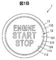
- FIG. 1B is a front view showing the start switch device.
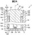
- FIG. 2A is a cross-sectional view illustrating a main part of the start switch device according to the first embodiment before a push operation.
- FIG. 2B is a cross-sectional view showing the main part after the push operation of the start switch device.
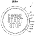
- FIG. 3A is a front view showing the start switch device according to the first embodiment before the push operation.
- FIG. 3B is a front view showing the start switch device after the push operation.
- FIG. 4A is a cross-sectional view illustrating a main part of the start switch device according to the second embodiment before a push operation.
- FIG. 4B is a cross-sectional view showing the main part after the push operation of the start switch device.
- a start switch device includes a bezel portion having an opening, an illumination unit that outputs illumination light in the opening, a push button that is disposed in the opening and moves in the opening by a push operation performed on an operation surface, It is equipped with.
- the bezel portion and the push button are configured so that the area of the gap between the bezel portion and the push button as viewed from the operation surface is changed by the movement of the push button accompanying the push operation compared to before the push operation.
- the amount of illumination light output from the gap can be changed so that the change in the area of the gap presents feedback for the push operation.
- the area of the gap gradually changes due to the movement of the push button, and the amount of illumination light changes, so that dynamic feedback can be presented in the process of operation.
- FIG. 1A is an explanatory view showing an example in which the start switch device according to the first embodiment is arranged inside the vehicle
- FIG. 1B is a front view showing the start switch device
- FIG. 2A is a cross-sectional view showing a main part before the push operation of the start switch device according to the first embodiment
- FIG. 2B is a cross-sectional view showing a main part after the push operation of the start switch device.
- FIG. 2A shows a reference state where no push operation is performed
- FIG. 2B shows a state where the push-in is completed.
- the ratio between figures may be different from the actual ratio.
- the start switch device 1 is disposed on a panel 90 in the vicinity of the steering of the vehicle 9 as shown in FIG. 1A.
- the start switch device 1 is a push switch that instructs start and stop of a drive device such as an engine or a motor of the vehicle 9.
- the vehicle 9 is based on a push operation performed on the start switch device 1 when, for example, the operator holds a regular portable device of the vehicle 9 and a predetermined condition is satisfied. Start the drive.
- This regular portable device is, for example, a portable device having an identification number corresponding to the vehicle 9.
- the recognition number is verified by communication with the vehicle 9.
- the predetermined condition is, for example, a condition that the operation position of the shift device is parking (P) and the brake pedal is operated.
- the vehicle 9 changes its state to ACC, OFF, for example, according to a push operation performed on the start switch device 1.
- the start switch device 1 is disposed in a bezel portion 11 having an opening 113, an illumination portion 16 that outputs illumination light 8 in the opening 113, and in the opening 113. And a push button 12 that moves in the opening 113 by a push operation performed.
- the area of the gap 112 between the bezel portion 11 and the push button 12 as viewed from the operation surface 121 is changed from that before the push operation by the movement of the push button 12 accompanying the push operation, and is output from the gap 112.
- the light amount of the illumination light 8 is changed to present feedback for the push operation.
- the start switch device 1 includes a light guide 14 that is disposed in the opening 113 and has an insertion opening 144 into which the push button 12 is inserted.
- the illumination light 8 propagates through the light guide 14 and is output from the gap 112.
- the bezel portion 11 is formed in a cylindrical shape from a metal material.
- the top surface 110 of the bezel portion 11 is exposed to the panel 90 together with the operation surface 121 of the push button 12 when the start switch device 1 is attached to the vehicle 9.
- the bezel part 11 inclines the outer peripheral side of the part which protrudes from the panel 90.
- a side surface 114 that is a first side surface of the opening 113 is inclined with respect to the moving shaft 3 of the push button 12. Specifically, as shown in FIGS. 2A and 2B, the side surface 114 is inclined so that the upper diameter of the opening 113 is larger than the lower diameter.
- the side surface 114 faces the side surface 122 that is the second side surface of the push button 12.
- the side surface 122 of the push button 12 is inclined with respect to the moving shaft 3.
- the side surface 114 and the side surface 122 are reflecting surfaces that reflect the illumination light 8.
- standard state in which push operation is not made is constant as shown, for example in FIG. 2A and 2B.
- the bezel part 11 is attached to the main body 10, for example.
- the main body 10 has, for example, a cylindrical shape having a bottom portion 101 formed using a synthetic resin.
- the substrate 2 is disposed on the bottom surface 102 of the bottom portion 101.
- the substrate 2 is, for example, a printed wiring board.
- the above-described illumination unit 16 and a micro switch 18 that is turned on by a push operation are arranged.
- the bezel portion 11 may be formed integrally with the main body 10.
- the main body 10 is formed of a synthetic resin, it is desirable to use a glossy synthetic resin that easily reflects the illumination light 8 on the side surface 114 of the bezel portion 11 or to perform a plating process.
- the main body 10 is provided with means for applying an elastic force in a direction opposite to the push operation direction to the push button 12 and means for holding the push button 12 in a reference state when the push operation is not performed.
- the means for applying the elastic force is a coil spring.
- the means for holding the push button 12 in the reference state is a groove provided on the inner surface 103 of the main body 10, and a convex portion protruding in the radial direction of the push button 12 is inserted into the groove.
- the push button 12 is formed in a cylindrical shape using, for example, a synthetic resin.
- the push button 12 includes, for example, an operation unit 120 and a column part 125 as shown in FIGS. 2A and 2B.
- the operation unit 120 has a disk shape with a radius larger than that of the columnar part 125. And the operation surface 121 which is the upper surface of the operation part 120 is a curved surface which swells outside. The operator performs a push operation so as to push the operation surface 121 into the bezel portion 11.
- the side surface 122 of the operation unit 120 is inclined with respect to the moving shaft 3. Specifically, the side surface 122 is inclined so that the upper diameter of the operation unit 120 is larger than the lower diameter.
- At least one side surface of the side surface 114 of the bezel portion 11 and the side surface 122 of the operation portion 120 may have a configuration in which the incident illumination light 8 is converted into a different color from that before entering and reflected. good.
- the operator pushes the push button 12.
- the color of the illumination light 8 to be output looks different. That is, the start switch device 1 has only one illumination unit 16 (light emitting element), and the illumination light 8 output from the start switch device 1 is animated by a push operation even though no control is performed. As shown in FIG. 4, the operator changes dynamically and is visually recognized by the operator.
- the cylindrical portion 125 protrudes from the lower surface 123 of the operation unit 120 and is inserted into the light guide 14. As an example, the end portion 126 of the cylindrical portion 125 is brought into contact with the microswitch 18 by a push operation performed on the push button 12 to turn the microswitch 18 on and off.
- the light guide 14 is formed in a cylindrical shape using a transparent resin material such as silicon resin.
- the cylindrical portion 125 of the push button 12 is inserted into the insertion opening 144 of the light guide 14.
- the light guide 14 has an inclined surface 141 that is inclined so as to face the side surface 114 in order to output the illumination light 8 propagating through the inside in the direction of the side surface 114 of the bezel portion 11.
- the slope 141 has a shape in which the outer peripheral side of the upper surface 140 is chamfered.
- An end surface 142 of the light guide 14 on the bottom 101 side faces the illumination unit 16.
- the illumination light 8 output from the illumination unit 16 enters the light guide 14 from the end surface 142 and spreads into the light guide 14, and is mainly output from the upper surface 140 and the inclined surface 141.
- the illumination light 8 output from the upper surface 140 and the inclined surface 141 is output from the gap 112 while reflecting the side surface 114 of the opening 113 and the side surface 122 of the operation unit 120 of the push button 12.
- the illumination light 8 in the reference state is output from the gap 112 that is an area surrounded by the inner periphery 111 of the bezel portion 11 and the outer periphery 124 of the push button 12 as shown in FIG. 1B. Therefore, the operator appears to shine around the push button 12.
- the illumination unit 16 includes, for example, one light emitting element such as an LED.
- the illumination unit 16 outputs the illumination light 8 with a constant light amount without changing the light amount.
- FIG. 3A is a front view showing the start switch device according to the first embodiment before the push operation
- FIG. 3B is a front view showing the start switch device after the push operation.
- the light emission area S 1 that is the area of the gap 112 from which the illumination light 8 is output in the front view is the inner circumference 111 of the bezel portion 11. And the area sandwiched between the outer periphery 124 of the operation unit 120.
- the interval between the side surface 114 of the bezel portion 11 and the side surface 122 of the operation portion 120 is smaller than the interval before the push operation, so that the gap from which the illumination light 8 is output.
- the distance between the side surface 114 and the side surface 122 does not change before and after the push operation.
- this interval is narrowed and the optical path of the illumination light 8 is narrowed.
- the illumination light 8 travels outside the bezel 11 while reflecting the side surface 114 of the bezel portion 11 and the side surface 122 of the push button 12.
- Emitting area S 2 of the illumination light 8 is output therefore, substantially, the area of the gap 112 surrounded by the outer periphery 124 of the dotted line and the push button 12 shown in Figure 3B.
- this dotted line connects the upper end of the side surface 122 of the push button 12 and the position where the upper end is projected onto the side surface 114 of the bezel portion 11, and the distance between the side surface 114 and the side surface 122 at this position is A gap 112 is formed.
- the push button 12 moves and the upper side surface 114 of the opening 113 can be seen, it looks as if the gap 112 has widened.
- the light emitting area S 2 of a region where the illumination light 8 is output is smaller than the light-emitting area S 1 in the reference state.
- the illumination light 8 output from the start switch device 1 appears weaker than the illumination light 8 in the reference state, even though the amount of the illumination light 8 output from the illumination unit 16 does not change.
- the emitting area S 2 since the push button 12 by the push operation continuously decreases from the light-emitting area S 1 as it is pushed, the illumination light 8 goes though weaker as animation to be output, that is dynamic Show changes. Therefore, the start switch device 1 can present this dynamic change as feedback of the push operation.
- the start switch device 1 can present dynamic feedback in the process of a push operation. Specifically, the start switch device 1, the amount of light emission area S 2 to the illumination light 8 by reducing gradually the area which the illumination light 8 is output is complete pushing the light emission area S 1 by the movement of the push button 12 Changes so that dynamic feedback can be presented in the course of operation.
- the start switch device 1 can present dynamic feedback with one illuminating unit 16 (light emitting element) without performing control, the manufacturing cost is lower than the case of controlling a plurality of light emitting elements. It is suppressed.
- the start switch device 1 includes the light guide 14, it can illuminate the periphery of the push button 12 so as to reduce unevenness compared to the case where the start guide device 1 is not provided.
- the start switch device 1 Since the start switch device 1 has the inclined surface 141 formed on the light guide 14, the illumination light 8 is emitted toward the side surface 114 of the bezel portion 11 more efficiently than the case where the inclined surface 141 is not formed. Can be brightly illuminated.
- the inclination direction of the side surface of the bezel portion and the side surface of the operation portion is different from the inclination direction of the first embodiment.
- FIG. 4A is a cross-sectional view showing a main part before the push operation of the start switch device according to the second embodiment
- FIG. 4B is a cross-sectional view showing a main part after the push operation of the start switch device.
- parts having the same functions and configurations as those of the first embodiment are denoted by the same reference numerals as those of the first embodiment, and description thereof is omitted.
- the start switch device 1 includes a bezel portion 11a, a push button 12a, and a light guide 14a.
- the side surface 114a of the opening 113a of the bezel portion 11 and the side surface 122a of the push button 12 facing the side surface 114a are inclined with respect to the moving shaft 3 of the push button 12a.
- the side surface 114a is inclined such that the upper diameter of the opening 113a is smaller than the lower diameter.
- the side surface 122a is inclined so that the upper diameter of the operation portion 120a is smaller than the lower diameter.
- a light guide 14a is disposed between the bezel portion 11a and the push button 12a.
- the light guide 14a has a cylindrical shape with a narrow upper portion.
- a push button 12a is inserted into the insertion opening 144a of the light guide 14a.
- the illumination light 8 is emitted from the upper surface 140a of the light guide 14a.
- the gap 112a between the side surface 114a of the bezel portion 11a and the side surface 122a of the operation portion 120a is larger than the gap 112a before the push operation, so that the illumination light 8 is output.
- emitting area S 3 is greater than the light emission area S 4 to.
- the illumination light 8 output from the start switch device 1 appears to be stronger than the illumination light 8 in the reference state, even though the light amount of the illumination light 8 output from the illumination unit 16 does not change.
- the light emitting area S 4 since the push button 12 by the push operation continuously increases from the light emitting area S 3 as pushed, the illumination light 8 goes though stronger as animation to be output, that is dynamic Show changes. Therefore, the start switch device 1 can present this dynamic change as feedback of the push operation.
- the side surface (side surface 114 and side surface 114a) of the bezel portion and the side surface (side surface 122 and side surface 122a) of the push button are flat surfaces without being uneven, but are not limited thereto, and may be curved surfaces. Moreover, the shape which a some surface has a level
- the start switch device 1 is a switch device that starts and stops the drive device of the vehicle 9, but is not limited to this, and is a switch device of an electronic device in which a push button moves by a push operation. Applicable.
Landscapes
- Engineering & Computer Science (AREA)
- Mechanical Engineering (AREA)
- Chemical & Material Sciences (AREA)
- Combustion & Propulsion (AREA)
- General Engineering & Computer Science (AREA)
- Push-Button Switches (AREA)
- Switch Cases, Indication, And Locking (AREA)
Abstract
スタートスイッチ装置1は、開口113を有するベゼル部11と、開口113内に照明光8を出力する照明部16と、開口113内に配置され、操作面121になされたプッシュ操作によって開口113内を移動するプッシュボタン12と、を備え、プッシュ操作に伴うプッシュボタン12の移動により、操作面121から見たベゼル部11とプッシュボタン12との隙間112の面積がプッシュ操作前と比べて変化して隙間112から出力される照明光8の光量を変化させるようにベゼル部11とプッシュボタン12が構成されている。
Description
本発明は、スタートスイッチ装置に関する。
スイッチユニットと、押圧操作に応じてスイッチユニットのスイッチング態様を切換える押しボタンと、を備えたスタート・ストップスイッチ装置が知られている(例えば、特許文献1参照。)。
特許文献1に開示されたスタート・ストップスイッチ装置は、さらにLED(Light Emission Diode)を有し、操作者の押圧操作により車両のエンジンのスタート及びストップを切り替えると共に、LEDを点灯及び消灯させて押圧操作に対するフィードバックを行っている。
特許文献1に開示されたスタート・ストップスイッチ装置は、押圧操作に対するフィードバックがLEDの点灯及び消灯しかなく、操作の過程において動的なフィードバックを呈示することができない。
本発明の目的は、操作の過程において動的なフィードバックを呈示することができるスタートスイッチ装置を提供することにある。
本発明の一実施形態によるスタートスイッチ装置は、開口を有するベゼル部と、開口内に照明光を出力する照明部と、開口内に配置され、操作面になされたプッシュ操作によって開口内を移動するプッシュボタンと、を備え、プッシュ操作に伴うプッシュボタンの移動により、操作面から見たベゼル部とプッシュボタンとの隙間の面積がプッシュ操作前と比べて変化するように前記ベゼル部と前記プッシュボタンが構成され、前記隙間の面積の変化が、前記プッシュ操作に対するフィードバックを呈示するように前記隙間から出力される前記照明光の光量を変化させる。
本発明の一実施形態によれば、操作の過程において動的なフィードバックを呈示することができるスタートスイッチ装置を提供することができる。
(実施形態の要約)
実施形態に係るスタートスイッチ装置は、開口を有するベゼル部と、開口内に照明光を出力する照明部と、開口内に配置され、操作面になされたプッシュ操作によって開口内を移動するプッシュボタンと、を備えている。このスタートスイッチ装置は、プッシュ操作に伴うプッシュボタンの移動により、操作面から見たベゼル部とプッシュボタンとの隙間の面積がプッシュ操作前と比べて変化するようにベゼル部とプッシュボタンが構成され、隙間の面積の変化が、プッシュ操作に対するフィードバックを呈示するように隙間から出力される照明光の光量を変化させることができる。
実施形態に係るスタートスイッチ装置は、開口を有するベゼル部と、開口内に照明光を出力する照明部と、開口内に配置され、操作面になされたプッシュ操作によって開口内を移動するプッシュボタンと、を備えている。このスタートスイッチ装置は、プッシュ操作に伴うプッシュボタンの移動により、操作面から見たベゼル部とプッシュボタンとの隙間の面積がプッシュ操作前と比べて変化するようにベゼル部とプッシュボタンが構成され、隙間の面積の変化が、プッシュ操作に対するフィードバックを呈示するように隙間から出力される照明光の光量を変化させることができる。
このスタートスイッチ装置は、プッシュボタンの移動によって隙間の面積が徐々に変化して照明光の光量が変化するので、操作の過程において動的なフィードバックを呈示することができる。
[第1の実施形態]
(スタートスイッチ装置1の概要)
図1Aは、第1の実施形態に係るスタートスイッチ装置が車両内部に配置された一例を示す説明図であり、図1Bは、スタートスイッチ装置を示す正面図である。図2Aは、第1の実施形態に係るスタートスイッチ装置のプッシュ操作前の要部を示す断面図であり、図2Bは、スタートスイッチ装置のプッシュ操作後の要部を示す断面図である。図2Aは、プッシュ操作が行われていない基準状態を示し、図2Bは、押し込みが完了した状態を示している。なお、以下に記載する実施形態に係る各図において、図形間の比率は、実際の比率とは異なる場合がある。
(スタートスイッチ装置1の概要)
図1Aは、第1の実施形態に係るスタートスイッチ装置が車両内部に配置された一例を示す説明図であり、図1Bは、スタートスイッチ装置を示す正面図である。図2Aは、第1の実施形態に係るスタートスイッチ装置のプッシュ操作前の要部を示す断面図であり、図2Bは、スタートスイッチ装置のプッシュ操作後の要部を示す断面図である。図2Aは、プッシュ操作が行われていない基準状態を示し、図2Bは、押し込みが完了した状態を示している。なお、以下に記載する実施形態に係る各図において、図形間の比率は、実際の比率とは異なる場合がある。
スタートスイッチ装置1は、一例として、図1Aに示すように、車両9のステアリング近傍のパネル90に配置されている。このスタートスイッチ装置1は、車両9のエンジンやモータなどの駆動装置の始動及び停止を指示するプッシュスイッチである。具体的には、車両9は、例えば、操作者が車両9の正規の携帯機を所持した状態で、かつ所定の条件が満たされている場合、スタートスイッチ装置1になされたプッシュ操作に基づいて駆動装置の始動を行う。
この正規の携帯機とは、例えば、車両9に対応した認識番号を有する携帯機である。認識番号は、車両9との通信によって照合される。また所定の条件とは、例えば、シフト装置の操作位置がパーキング(P)であり、かつブレーキペダルが操作されているという条件である。車両9は、所定の条件が満たされていない場合、例えば、スタートスイッチ装置1になされたプッシュ操作に応じてACC、OFFと状態が遷移する。
スタートスイッチ装置1は、図1A及び1Bに示すように、開口113を有するベゼル部11と、開口113内に照明光8を出力する照明部16と、開口113内に配置され、操作面121になされたプッシュ操作によって開口113内を移動するプッシュボタン12と、を備えている。
そしてスタートスイッチ装置1は、プッシュ操作に伴うプッシュボタン12の移動により、操作面121から見たベゼル部11とプッシュボタン12との隙間112の面積がプッシュ操作前と変化して隙間112から出力される照明光8の光量を変化させ、プッシュ操作に対するフィードバックを呈示するように構成されている。
またスタートスイッチ装置1は、開口113内に配置され、プッシュボタン12が挿入される挿入開口144を有するライトガイド14を備えている。照明光8は、このライトガイド14を伝播して隙間112から出力される。
(ベゼル部11の構成)
ベゼル部11は、金属材料によって円筒形状に形成されている。このベゼル部11の上面110は、スタートスイッチ装置1が車両9に取り付けられると、プッシュボタン12の操作面121と共にパネル90に露出する。そしてベゼル部11は、パネル90から突出する部分の外周側が傾斜している。
ベゼル部11は、金属材料によって円筒形状に形成されている。このベゼル部11の上面110は、スタートスイッチ装置1が車両9に取り付けられると、プッシュボタン12の操作面121と共にパネル90に露出する。そしてベゼル部11は、パネル90から突出する部分の外周側が傾斜している。
ベゼル部11は、開口113の第1の側面である側面114がプッシュボタン12の移動軸3に対して傾斜している。具体的には、側面114は、図2A及び2Bに示すように、開口113の上側の径が下側の径より大きくなるように傾斜している。
この側面114は、プッシュボタン12の第2の側面である側面122と対向している。そしてプッシュボタン12の側面122は、移動軸3に対して傾斜している。この側面114及び側面122は、照明光8を反射する反射面となっている。なおプッシュ操作がなされていない基準状態における側面114及び側面122の間隔は、例えば、図2A及び2Bに示すように、一定である。
ベゼル部11は、例えば、本体10に取り付けられている。この本体10は、例えば、合成樹脂を用いて形成された底部101を有する円筒形状を有している。この底部101の底面102には、例えば、基板2が配置されている。基板2は、例えば、プリント配線基板である。この基板2には、例えば、上述の照明部16と、プッシュ操作によってオンするマイクロスイッチ18と、が配置されている。
なお変形例としてベゼル部11は、本体10と一体に形成されても良い。本体10が合成樹脂から形成される場合、ベゼル部11の側面114に照明光8を反射し易い光沢のある合成樹脂を用いたり、メッキ処理を行ったりすることが望ましい。
本体10には、プッシュボタン12に対してプッシュ操作方向とは反対方向の弾性力を作用させる手段と、プッシュ操作がなされていない場合にプッシュボタン12を基準状態に保持する手段と、が配置されている。弾性力を作用させる手段は、一例として、コイルスプリングである。プッシュボタン12を基準状態に保持する手段は、一例として、本体10の内面103に設けられた溝であり、プッシュボタン12の径方向に突出する凸部が当該溝に挿入される。
(プッシュボタン12の構成)
プッシュボタン12は、例えば、合成樹脂を用いて円柱形状に形成されている。このプッシュボタン12は、例えば、図2A及び2Bに示すように、操作部120と、円柱部125と、を備えている。
プッシュボタン12は、例えば、合成樹脂を用いて円柱形状に形成されている。このプッシュボタン12は、例えば、図2A及び2Bに示すように、操作部120と、円柱部125と、を備えている。
操作部120は、円柱部125よりも半径が大きい円板形状を有している。そして操作部120の上面である操作面121は、外側に膨らむ曲面となっている。操作者は、この操作面121をベゼル部11に押し込むようにプッシュ操作を行う。
この操作部120の側面122は、上述したように、移動軸3に対して傾斜している。具体的には、側面122は、操作部120の上側の径が下側の径より大きくなるように傾斜している。
変形例として、ベゼル部11の側面114、及び操作部120の側面122の少なくとも一方の側面が、入射する照明光8を入射する前と異なる色に変換して反射する構成を有していても良い。一例として、側面114及び側面122の少なくとも一方が、異なる波長の光を吸収する複数のフィルタ膜を移動軸3に沿って並んで有していた場合、操作者には、プッシュボタン12を押し込むにつれて出力される照明光8の色が異なって見える。つまりスタートスイッチ装置1は、1つの照明部16(発光素子)を有するのみであり、かつなんら制御を行っていないにも関わらず、スタートスイッチ装置1から出力される照明光8がプッシュ操作によってアニメーションのように、動的に変化して操作者に視認される。
円柱部125は、操作部120の下面123から突出し、ライトガイド14に挿入されている。この円柱部125の端部126は、一例として、プッシュボタン12になされたプッシュ操作によってマイクロスイッチ18と接触し、マイクロスイッチ18をオン及びオフさせる。
(ライトガイド14の構成)
ライトガイド14は、一例として、シリコン樹脂などの透明な樹脂材料を用いて円筒形状に形成されている。このライトガイド14の挿入開口144には、プッシュボタン12の円柱部125が挿入されている。
ライトガイド14は、一例として、シリコン樹脂などの透明な樹脂材料を用いて円筒形状に形成されている。このライトガイド14の挿入開口144には、プッシュボタン12の円柱部125が挿入されている。
ライトガイド14は、内部を伝播した照明光8をベゼル部11の側面114方向に出力させるために側面114と面するように傾斜する斜面141を有している。この斜面141は、上面140の外周側が面取りされたような形状を有している。
ライトガイド14の底部101側の端面142は、照明部16と対向している。照明部16から出力された照明光8は、端面142からライトガイド14内に入射してライトガイド14内に広がり、主に上面140及び斜面141から出力される。この上面140及び斜面141から出力した照明光8は、開口113の側面114及びプッシュボタン12の操作部120の側面122を反射しながら隙間112から出力する。
言い換えるなら、基準状態における照明光8は、図1Bに示すように、ベゼル部11の内周111と、プッシュボタン12の外周124と、に囲まれた領域である隙間112から出力する。従って操作者は、プッシュボタン12の周囲が光るように見える。
(照明部16の構成)
照明部16は、例えば、LEDなどの1つの発光素子を備えている。この照明部16は、光量を変えず、一定の光量の照明光8を出力する。
照明部16は、例えば、LEDなどの1つの発光素子を備えている。この照明部16は、光量を変えず、一定の光量の照明光8を出力する。
(隙間112から出力される照明光8の変化について)
図3Aは、プッシュ操作前の第1の実施形態に係るスタートスイッチ装置を示す正面図であり、図3Bは、プッシュ操作後のスタートスイッチ装置を示す正面図である。
図3Aは、プッシュ操作前の第1の実施形態に係るスタートスイッチ装置を示す正面図であり、図3Bは、プッシュ操作後のスタートスイッチ装置を示す正面図である。
スタートスイッチ装置1は、図2A及び3Aに示すように、プッシュ操作前の基準状態では、正面視において照明光8が出力する隙間112の面積である発光面積S1がベゼル部11の内周111と操作部120の外周124に挟まれた面積となる。
図2B及び3Bに示すように、プッシュ操作がなされると、ベゼル部11の側面114と操作部120の側面122の間隔がプッシュ操作前の間隔よりも小さくなるので、照明光8が出力する隙間112が縮小して発光面積S2が発光面積S1よりも小さくなる。
具体的には、側面114と側面122が移動軸3に対して傾斜していない場合、プッシュ操作の前後において側面114と側面122との間隔は、変化しない。しかし側面114と側面122が移動軸3に対して傾斜しているので、この間隔が狭くなり、照明光8の光路が狭くなる。
照明光8は、図2Bに示すように、ベゼル部11の側面114とプッシュボタン12の側面122を反射しながらベゼル部11の外に向かう。従って照明光8が出力する発光面積S2は、ほぼ、図3Bに示す点線とプッシュボタン12の外周124で囲まれた隙間112の面積となる。この点線は、図2Bに示すように、プッシュボタン12の側面122の上端とこの上端をベゼル部11の側面114に投影した位置とを結んでおり、この位置における側面114と側面122の間隔が隙間112となる。
プッシュボタン12が移動して開口113の上部の側面114が見えるため、隙間112が広がったように見かけ上見える。しかし上述のように、照明光8が出力する領域の発光面積S2が基準状態の発光面積S1よりも小さくなる。その結果、照明部16から出力される照明光8の光量が変わらないにも関わらず、スタートスイッチ装置1から出力される照明光8は、基準状態の照明光8よりも弱く見える。
この発光面積S2は、プッシュ操作によってプッシュボタン12が押し込まれるにつれて発光面積S1から連続的に小さくなるので、出力される照明光8があたかもアニメーションのように弱くなっていく、つまり動的な変化を見せる。従ってスタートスイッチ装置1は、この動的な変化をプッシュ操作のフィードバックとして呈示することができる。
(第1の実施形態の効果)
本実施形態に係るスタートスイッチ装置1は、プッシュ操作の過程において動的なフィードバックを呈示することができる。具体的には、スタートスイッチ装置1は、プッシュボタン12の移動によって照明光8が出力される面積が発光面積S1から押し込みが完了した発光面積S2まで徐々に縮小して照明光8の光量が変化するので、操作の過程において動的なフィードバックを呈示することができる。
本実施形態に係るスタートスイッチ装置1は、プッシュ操作の過程において動的なフィードバックを呈示することができる。具体的には、スタートスイッチ装置1は、プッシュボタン12の移動によって照明光8が出力される面積が発光面積S1から押し込みが完了した発光面積S2まで徐々に縮小して照明光8の光量が変化するので、操作の過程において動的なフィードバックを呈示することができる。
スタートスイッチ装置1は、1つの照明部16(発光素子)で、かつ制御を行うことなく動的なフィードバックを呈示することができるので、複数の発光素子を制御する場合と比べて、製造コストが抑制される。
スタートスイッチ装置1は、ライトガイド14を備えているので、備えていない場合と比べて、むらが少なくなるようにプッシュボタン12の周囲を照明することができる。
スタートスイッチ装置1は、ライトガイド14に斜面141が形成されているので、形成されない場合と比べて、効率良くベゼル部11の側面114に向けて照明光8を出射し、プッシュボタン12の周囲を明るく照明することができる。
[第2の実施形態]
第2の実施形態は、ベゼル部の側面と操作部の側面の傾斜方向が第1の実施形態の傾斜方向と異なっている。
第2の実施形態は、ベゼル部の側面と操作部の側面の傾斜方向が第1の実施形態の傾斜方向と異なっている。
図4Aは、第2の実施形態に係るスタートスイッチ装置のプッシュ操作前の要部を示す断面図であり、図4Bは、スタートスイッチ装置のプッシュ操作後の要部を示す断面図である。なお以下に記載する実施形態において、第1の実施形態と同じ機能及び構成を有する部分は、第1の実施形態と同じ符号を付し、その説明は省略するものとする。
スタートスイッチ装置1は、図4A及び4Bに示すように、ベゼル部11aと、プッシュボタン12aと、ライトガイド14aと、を備えている。
このスタートスイッチ装置1は、ベゼル部11の開口113aの側面114a、及び側面114aと対向するプッシュボタン12の側面122aがプッシュボタン12aの移動軸3に対して傾斜している。
具体的には、側面114aは、開口113aの上側の径が下側の径より小さくなるように傾斜している。また側面122aは、操作部120aの上側の径が下側の径より小さくなるように傾斜している。
このベゼル部11aとプッシュボタン12aの間には、ライトガイド14aが配置されている。このライトガイド14aは、上部が狭まった円筒形状を有している。そしてライトガイド14aの挿入開口144aには、プッシュボタン12aが挿入されている。照明光8は、ライトガイド14aの上面140aから出射する。
図4A及び4Bに示すように、プッシュ操作がなされると、ベゼル部11aの側面114aと操作部120aの側面122aの隙間112aがプッシュ操作前の隙間112aよりも大きくなるので、照明光8が出力する発光面積S3が発光面積S4よりも大きくなる。その結果、照明部16から出力される照明光8の光量が変わらないにも関わらず、スタートスイッチ装置1から出力される照明光8は、基準状態の照明光8よりも強く見える。
この発光面積S4は、プッシュ操作によってプッシュボタン12が押し込まれるにつれて発光面積S3から連続的に大きくなるので、出力される照明光8があたかもアニメーションのように強くなっていく、つまり動的な変化を見せる。従ってスタートスイッチ装置1は、この動的な変化をプッシュ操作のフィードバックとして呈示することができる。
なお上述の実施形態においてベゼル部の側面(側面114及び側面114a)、及びプッシュボタンの側面(側面122及び側面122a)は、凹凸の無い平面であったが、これに限定されず曲面でも良く、また複数の面が段差を有して連結する形状であっても良い。この場合、発光面積は、線形に変化せずに非線形に変化するので、プッシュボタンの押し込みに従って出力する照明光8が非線形に変化する。
また上述の実施形態に係るスタートスイッチ装置1は、車両9の駆動装置を始動及び停止させるスイッチ装置であったが、これに限定されず、プッシュ操作によってプッシュボタンが移動する電子機器のスイッチ装置に応用可能である。
以上、本発明のいくつかの実施形態及び変形例を説明したが、これらの実施形態及び変形例は、一例に過ぎず、特許請求の範囲に係る発明を限定するものではない。これら新規な実施形態及び変形例は、その他の様々な形態で実施されることが可能であり、本発明の要旨を逸脱しない範囲で、種々の省略、置き換え、変更などを行うことができる。また、これら実施形態及び変形例の中で説明した特徴の組合せの全てが発明の課題を解決するための手段に必須であるとは限らない。さらに、これら実施形態及び変形例は、発明の範囲及び要旨に含まれると共に、特許請求の範囲に記載された発明とその均等の範囲に含まれる。
1 スタートスイッチ装置
8 照明光
11,11a ベゼル部
12,12a プッシュボタン
14,14a ライトガイド
16 照明部
112,112a 隙間
113,113a 開口
114,114a 側面
121 操作面
122,122a 側面
141 斜面
8 照明光
11,11a ベゼル部
12,12a プッシュボタン
14,14a ライトガイド
16 照明部
112,112a 隙間
113,113a 開口
114,114a 側面
121 操作面
122,122a 側面
141 斜面
Claims (6)
- 開口を有するベゼル部と、
前記開口内に照明光を出力する照明部と、
前記開口内に配置され、操作面になされたプッシュ操作によって前記開口内を移動するプッシュボタンと、を備え、
前記プッシュ操作に伴う前記プッシュボタンの移動により、前記操作面から見た前記ベゼル部と前記プッシュボタンとの隙間の面積が、前記プッシュ操作前と比べて変化するように前記ベゼル部と前記プッシュボタンが構成され、
前記隙間の面積の変化が、前記プッシュ操作に対するフィードバックを呈示するように前記隙間から出力される前記照明光の光量を変化させるスタートスイッチ装置。 - 前記ベゼル部の前記開口の第1の側面、及び前記第1の側面と対向する前記プッシュボタンの第2の側面が前記プッシュボタンの移動軸に対して傾斜する、請求項1に記載のスタートスイッチ装置。
- 更に、前記開口内に配置され、前記プッシュボタンが挿入される挿入開口を有するライトガイドを備え、前記照明光が前記ライトガイドを伝播して前記隙間から出力される、請求項1又は2に記載のスタートスイッチ装置。
- 前記ライトガイドは、内部を伝播した前記照明光を前記第1の側面方向に出力させるために前記第1の側面と面するように傾斜する斜面を有する、請求項3に記載のスタートスイッチ装置。
- 前記隙間の面積は、前記プッシュボタンの移動に従って連続的に減少する、請求項1~4の何れか1項に記載のスタートスイッチ装置。
- 前記隙間の面積は、前記プッシュボタンの移動に従って連続的に増加する、請求項1~4の何れか1項に記載のスタートスイッチ装置。
Applications Claiming Priority (2)
| Application Number | Priority Date | Filing Date | Title |
|---|---|---|---|
| JP2016013449A JP2017134985A (ja) | 2016-01-27 | 2016-01-27 | スタートスイッチ装置 |
| JP2016-013449 | 2016-01-27 |
Publications (1)
| Publication Number | Publication Date |
|---|---|
| WO2017130816A1 true WO2017130816A1 (ja) | 2017-08-03 |
Family
ID=59397746
Family Applications (1)
| Application Number | Title | Priority Date | Filing Date |
|---|---|---|---|
| PCT/JP2017/001557 Ceased WO2017130816A1 (ja) | 2016-01-27 | 2017-01-18 | スタートスイッチ装置 |
Country Status (2)
| Country | Link |
|---|---|
| JP (1) | JP2017134985A (ja) |
| WO (1) | WO2017130816A1 (ja) |
Cited By (2)
| Publication number | Priority date | Publication date | Assignee | Title |
|---|---|---|---|---|
| CN110789467A (zh) * | 2019-11-13 | 2020-02-14 | 汕头市科来福电子有限公司 | 一种具有记忆功能的自动启停关闭器开关总成 |
| CN111630468A (zh) * | 2018-01-19 | 2020-09-04 | 路创技术有限责任公司 | 具有照亮的按钮的小键盘 |
Families Citing this family (6)
| Publication number | Priority date | Publication date | Assignee | Title |
|---|---|---|---|---|
| JP6656030B2 (ja) * | 2016-03-10 | 2020-03-04 | シャープ株式会社 | 押ボタンスイッチ |
| JP6936972B2 (ja) * | 2017-10-31 | 2021-09-22 | トヨタ自動車株式会社 | 車載用照明装置 |
| JP6770548B2 (ja) | 2018-04-05 | 2020-10-14 | 株式会社東海理化電機製作所 | スイッチ装置 |
| JP6936760B2 (ja) | 2018-04-05 | 2021-09-22 | 株式会社東海理化電機製作所 | スイッチ装置 |
| CN120754529A (zh) | 2020-03-31 | 2025-10-10 | 索尼互动娱乐股份有限公司 | 输入设备 |
| JP7203785B2 (ja) | 2020-03-31 | 2023-01-13 | 株式会社ソニー・インタラクティブエンタテインメント | 入力デバイス |
Citations (7)
| Publication number | Priority date | Publication date | Assignee | Title |
|---|---|---|---|---|
| JPH05101738A (ja) * | 1991-10-11 | 1993-04-23 | Matsushita Electric Ind Co Ltd | キーボード |
| JP2001352379A (ja) * | 2000-06-07 | 2001-12-21 | Matsushita Electric Ind Co Ltd | 通信端末装置 |
| JP2006164573A (ja) * | 2004-12-02 | 2006-06-22 | Tokai Rika Co Ltd | 車両用スイッチ |
| JP2009170309A (ja) * | 2008-01-17 | 2009-07-30 | Teac Corp | リング状ライトガイド及びこれを備えた電子機器 |
| JP2009193716A (ja) * | 2008-02-12 | 2009-08-27 | Sumitomo Wiring Syst Ltd | 照明機能を有する操作装置 |
| JP2013100818A (ja) * | 2012-12-05 | 2013-05-23 | Honda Lock Mfg Co Ltd | エンジンのスタート・ストップスイッチ装置 |
| JP2015076283A (ja) * | 2013-10-09 | 2015-04-20 | 株式会社光波 | 自動販売機用選択スイッチ装置 |
-
2016
- 2016-01-27 JP JP2016013449A patent/JP2017134985A/ja active Pending
-
2017
- 2017-01-18 WO PCT/JP2017/001557 patent/WO2017130816A1/ja not_active Ceased
Patent Citations (7)
| Publication number | Priority date | Publication date | Assignee | Title |
|---|---|---|---|---|
| JPH05101738A (ja) * | 1991-10-11 | 1993-04-23 | Matsushita Electric Ind Co Ltd | キーボード |
| JP2001352379A (ja) * | 2000-06-07 | 2001-12-21 | Matsushita Electric Ind Co Ltd | 通信端末装置 |
| JP2006164573A (ja) * | 2004-12-02 | 2006-06-22 | Tokai Rika Co Ltd | 車両用スイッチ |
| JP2009170309A (ja) * | 2008-01-17 | 2009-07-30 | Teac Corp | リング状ライトガイド及びこれを備えた電子機器 |
| JP2009193716A (ja) * | 2008-02-12 | 2009-08-27 | Sumitomo Wiring Syst Ltd | 照明機能を有する操作装置 |
| JP2013100818A (ja) * | 2012-12-05 | 2013-05-23 | Honda Lock Mfg Co Ltd | エンジンのスタート・ストップスイッチ装置 |
| JP2015076283A (ja) * | 2013-10-09 | 2015-04-20 | 株式会社光波 | 自動販売機用選択スイッチ装置 |
Cited By (5)
| Publication number | Priority date | Publication date | Assignee | Title |
|---|---|---|---|---|
| CN111630468A (zh) * | 2018-01-19 | 2020-09-04 | 路创技术有限责任公司 | 具有照亮的按钮的小键盘 |
| CN111630468B (zh) * | 2018-01-19 | 2022-07-05 | 路创技术有限责任公司 | 具有照亮的按钮的小键盘 |
| US11776772B2 (en) | 2018-01-19 | 2023-10-03 | Lutron Technology Company Llc | Keypad having illuminated buttons |
| US12176159B2 (en) | 2018-01-19 | 2024-12-24 | Lutron Technology Company Llc | Keypad having illuminated buttons |
| CN110789467A (zh) * | 2019-11-13 | 2020-02-14 | 汕头市科来福电子有限公司 | 一种具有记忆功能的自动启停关闭器开关总成 |
Also Published As
| Publication number | Publication date |
|---|---|
| JP2017134985A (ja) | 2017-08-03 |
Similar Documents
| Publication | Publication Date | Title |
|---|---|---|
| WO2017130816A1 (ja) | スタートスイッチ装置 | |
| JP5986430B2 (ja) | 照光表示スイッチ装置 | |
| JP5986432B2 (ja) | 照光表示スイッチ装置 | |
| US7423886B2 (en) | Electronic member and rotary electronic component | |
| CN101622682B (zh) | 具有照明功能的操作装置 | |
| US9837228B2 (en) | Illuminated keyboard with optical switch | |
| KR20140148477A (ko) | 디스플레이 스위치 | |
| KR20170107576A (ko) | 키보드 | |
| CN101802951A (zh) | 显示装置和按键装置 | |
| JP2009009790A (ja) | 照光スイッチ | |
| JP4609247B2 (ja) | 発光スイッチ | |
| JP6496995B2 (ja) | インジケータ | |
| WO2018131137A1 (ja) | 操作部構造およびこれを備えた電子機器 | |
| JP2009026576A (ja) | 携帯端末用操作スイッチ | |
| JP4974752B2 (ja) | 照明式スイッチ装置 | |
| JP4662283B2 (ja) | スイッチ装置 | |
| JP7597256B2 (ja) | スイッチノブの照明構造 | |
| KR101550576B1 (ko) | 차량용 광 스위치 | |
| KR101915112B1 (ko) | 매립형 조명장치 | |
| JP2019040662A (ja) | スイッチ装置 | |
| JP2008034121A (ja) | スイッチ装置 | |
| JP2007134080A (ja) | 照光式押しボタン装置 | |
| JPH0343630Y2 (ja) | ||
| US20130258675A1 (en) | Light-emitting structure | |
| CN120202519A (zh) | 按钮开关以及控制器 |
Legal Events
| Date | Code | Title | Description |
|---|---|---|---|
| 121 | Ep: the epo has been informed by wipo that ep was designated in this application |
Ref document number: 17744046 Country of ref document: EP Kind code of ref document: A1 |
|
| NENP | Non-entry into the national phase |
Ref country code: DE |
|
| 122 | Ep: pct application non-entry in european phase |
Ref document number: 17744046 Country of ref document: EP Kind code of ref document: A1 |