WO2017130718A1 - ひび割れ検出装置、ひび割れ検出方法及びプログラム - Google Patents
ひび割れ検出装置、ひび割れ検出方法及びプログラム Download PDFInfo
- Publication number
- WO2017130718A1 WO2017130718A1 PCT/JP2017/000813 JP2017000813W WO2017130718A1 WO 2017130718 A1 WO2017130718 A1 WO 2017130718A1 JP 2017000813 W JP2017000813 W JP 2017000813W WO 2017130718 A1 WO2017130718 A1 WO 2017130718A1
- Authority
- WO
- WIPO (PCT)
- Prior art keywords
- edge
- image
- density
- crack
- unit
- Prior art date
- Legal status (The legal status is an assumption and is not a legal conclusion. Google has not performed a legal analysis and makes no representation as to the accuracy of the status listed.)
- Ceased
Links
Images













Classifications
-
- G—PHYSICS
- G01—MEASURING; TESTING
- G01N—INVESTIGATING OR ANALYSING MATERIALS BY DETERMINING THEIR CHEMICAL OR PHYSICAL PROPERTIES
- G01N21/00—Investigating or analysing materials by the use of optical means, i.e. using sub-millimetre waves, infrared, visible or ultraviolet light
- G01N21/84—Systems specially adapted for particular applications
- G01N21/88—Investigating the presence of flaws or contamination
-
- G—PHYSICS
- G06—COMPUTING OR CALCULATING; COUNTING
- G06T—IMAGE DATA PROCESSING OR GENERATION, IN GENERAL
- G06T1/00—General purpose image data processing
Definitions
- the present invention relates to a crack detection device, a crack detection method, and a program, and more particularly, to a crack detection device, a crack detection method, and a program for easily detecting a crack from an image of a surface of a structure.
- Patent Document 1 describes a crack detection method using wavelet transform. According to this technique, even when it is difficult to detect cracks due to dirt on the captured concrete surface or lighting conditions, it is possible to easily perform high-accuracy crack detection.
- Patent Document 2 describes a technique for extracting pixels having the same color as a concrete structure and having the same texture as the concrete structure as candidate concrete areas. According to this technique, it is possible to remove the background and / or obstacles other than the concrete surface from the captured image of the concrete structure.
- JP 2014-228357 A Japanese Unexamined Patent Publication No. 2011-163866
- the present invention has been made in view of such circumstances, and a crack detection device, a crack detection method, and a program capable of detecting cracks even when linear structures are densely present on the surface of the structure.
- the purpose is to provide.
- one aspect of a crack detection device includes an image acquisition unit that acquires an image of a surface of a structure, an edge detection unit that detects an edge for each direction from the image of the surface of the structure, and an image The edge density for each direction is calculated for a plurality of areas, and the edge density exists in an area where the edge density is higher than the first threshold value, and any one of the directions in which the edge density is higher than the first threshold value
- An edge erasing section for erasing the edge of the structure from the region, and a crack extracting section for extracting a crack on the surface of the structure from the edge.
- the edge for each direction is detected from the image of the surface of the structure, the density of the edge for each direction is calculated for a plurality of regions of the image, and the edge density exists in a region higher than the first threshold value. Since the edge in any one of the directions in which the density of the edge is higher than the first threshold is erased and the crack on the surface of the structure is extracted from the edge, a line is drawn on the surface of the structure. Even if the structure is densely present, cracks can be detected.
- the edge erasing unit erases an edge in a region where the edge density is higher than the first threshold value and having the highest edge density from the region. Thereby, the noise by a linear structure can be excluded appropriately.
- the edge detection unit detects an edge for each intensity from the image of the surface of the structure, and the edge erasure unit calculates an edge density for each intensity for a plurality of regions of the image, and the edge density is higher than the second threshold value. It is preferable that an edge having any one of the intensities whose edge density is higher than the second threshold is erased from the area. Thereby, the noise by a linear structure can be excluded appropriately.
- one aspect of the crack detection apparatus includes an image acquisition unit that acquires an image of the surface of the structure, an edge detection unit that detects an edge for each intensity from the image of the surface of the structure, and an image The edge density for each intensity is calculated for a plurality of areas, and any one of the intensities having an edge density higher than the first threshold and having an edge density higher than the first threshold.
- An edge erasing section for erasing the edge of the structure from the region, and a crack extracting section for extracting a crack on the surface of the structure from the edge.
- the edge for each intensity is detected from the image of the surface of the structure, the density of the edge for each intensity is calculated for a plurality of areas of the image, and the edge density exists in an area higher than the first threshold value. Since the edge having an edge density that is higher than the first threshold is deleted, a crack on the surface of the structure is extracted from the edge. Even if the structure is densely present, cracks can be detected.
- the edge erasing unit erases an edge having an intensity with the highest edge density from the area, which is an edge existing in the area where the edge density is higher than the first threshold value. Thereby, the noise by a linear structure can be excluded appropriately.
- the edge detection unit detects an edge with a plurality of spatial resolutions. Thereby, the noise by a linear structure can be excluded appropriately irrespective of the thickness of a linear structure.
- the edge erasing unit preferably calculates the density of the number of pixels on the edge. Further, the edge erasing unit may calculate the density of line segments of the edge. Thereby, the density of the edge can be calculated appropriately.
- the edge eraser does not erase an edge having a length longer than the third threshold from the region. Thereby, only the noise by a linear structure can be excluded appropriately.
- a display control unit configured to display the detected edge on the display unit; and an input unit configured to allow a user to select an edge to be erased from the region among the edges displayed on the display unit. Is preferably erased from the region. Thereby, only the noise by a linear structure can be excluded appropriately.
- one aspect of the crack detection method includes an image acquisition step of acquiring an image of the surface of the structure, an edge detection step of detecting an edge for each direction from the image of the surface of the structure, and an image The edge density for each direction is calculated for a plurality of areas, and the edge density exists in an area where the edge density is higher than the first threshold value, and any one of the directions in which the edge density is higher than the first threshold value
- An edge erasing process for erasing the edge of the structure from the region and a crack extracting process for extracting a crack on the surface of the structure from the edge.
- the edge for each direction is detected from the image of the surface of the structure, the density of the edge for each direction is calculated for a plurality of regions of the image, and the edge density exists in a region higher than the first threshold value.
- the edge of any one of the directions in which the density of the edges is higher than the first threshold is erased from the region, and the crack of the surface of the structure is extracted from the edge. Even if the linear structures are densely present, cracks can be detected.
- one aspect of the crack detection method includes an image acquisition step of acquiring an image of the surface of the structure, an edge detection step of detecting an edge for each intensity from the image of the surface of the structure, and an image The edge density for each intensity is calculated for a plurality of areas, and any one of the intensities having an edge density higher than the first threshold and having an edge density higher than the first threshold.
- the edge for each intensity is detected from the image of the surface of the structure, the density of the edge for each intensity is calculated for a plurality of areas of the image, and the edge density exists in an area higher than the first threshold value.
- the edge of the edge having the density higher than the first threshold is erased from the region, and the crack on the surface of the structure is extracted from the edge. Even if the linear structures are densely present, cracks can be detected.
- a program for causing a computer to execute the crack detection method is also included in one aspect for achieving the above object.
- cracks can be detected even when linear structures are densely present on the surface of the structure.
- FIG. 18 is a partially enlarged view of FIG. 17. It is a figure which shows the legend of the direction of the pixel of an edge.
- FIG. 1 is an overall configuration diagram of a computer including a crack detection apparatus according to the present embodiment.
- the computer 300 includes the crack detection device 100 (see FIG. 6), acquires an image of the surface of the concrete column 1 captured by the camera 200, and analyzes the acquired image to generate the crack in the concrete column 1. Crack 2 is detected.
- the concrete pillar 1 is an object of crack detection performed by the computer 300.
- the crack detection target is not limited to a concrete pillar, and a wall or floor (an example of a structure) such as a metal structure or a wooden structure can be used as the target.
- damage such as free lime can be detected.
- the computer 300 acquires an image of a target for crack detection from the camera 200.
- the camera 200 captures the surface of the concrete pillar 1 (an example of the surface of a structure) and transmits the captured image to the computer 300 wirelessly or by wire.
- the computer 300 may acquire an image by capturing an object to be detected with a built-in camera 305 (see FIG. 3), which will be described later, or a USB (connected to the external connection terminal 306 (see FIG. 2)).
- the image may be acquired by reading from a recording medium such as a Universal (Serial Bus) memory.
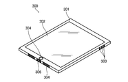
- FIG. 2 is a front perspective view of the computer 300
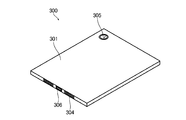
- FIG. 3 is a rear perspective view.
- the computer 300 is configured as a tablet computer.
- the computer 300 includes a flat casing 301 having a rectangular outline, and the casing 301 includes a touch panel display 302, operation buttons 303, a speaker 304, a built-in camera 305, an external connection terminal 306, and the like. .
- FIG. 4 is a block diagram showing a system configuration of the computer 300.
- a computer 300 includes a CPU (Central Processing Unit) 310 that controls the overall operation of the computer 300, and a main memory 314, a non-volatile memory 316, a mobile device via a system bus 312 to the CPU 310.
- a communication unit 318, a wireless LAN (Local Area Network) communication unit 320, a short-range wireless communication unit 322, a wired communication unit 324, a display unit 326, an input unit 328, a key input unit 330, an audio processing unit 332, and an image processing unit 334 Etc. are connected.
- the CPU 310 reads an operation program (OS (Operating System) and an application program that operates on the OS), standard data, and the like stored in the non-volatile memory 316, expands them in the main memory 314, and executes the operation program It functions as a control unit that controls the operation of the entire computer.
- OS Operating System
- the main memory 314 is composed of, for example, a RAM (Random Access Memory) and functions as a work memory for the CPU 310.
- the non-volatile memory 316 is composed of, for example, a flash EEPROM (Electrically Erasable Programmable Read Only Memory), and stores the above-described operation program and various standard data.
- the nonvolatile memory 316 functions as a storage unit of the computer 300 and stores various data.
- the mobile communication unit 318 includes an antenna based on a third generation mobile communication system compliant with the IMT-2000 (International Mobile Telecommunication 2000) standard and a fourth generation mobile communication system compliant with the IMT-Advanced (International Mobile Telecommunications-Advanced) standard. Data is transmitted / received to / from a nearby base station (not shown) via 318A.
- IMT-2000 International Mobile Telecommunication 2000
- IMT-Advanced International Mobile Telecommunications-Advanced
- the wireless LAN communication unit 320 is connected to a wireless LAN access point or an external device capable of wireless LAN communication via an antenna 320A, such as IEEE (Institute of Electrical and Electronics Electronics) (802.11a / b / g / n standard). Wireless LAN communication in accordance with the wireless LAN communication standard.
- IEEE Institute of Electrical and Electronics Electronics
- the short-range wireless communication unit 322 performs communication with other Bluetooth (registered trademark) equipment in the range of, for example, class 2 (within a radius of about 10 m) via the antenna 322A.
- Bluetooth registered trademark
- the wired communication unit 324 performs communication according to a predetermined communication standard with an external device connected with a cable (not shown) via the external connection terminal 306.
- the display unit 326 includes a color LCD (Liquid Crystal Display) panel that constitutes a display portion of the touch panel display 302 and a driving circuit thereof, and displays various images on the color LCD panel.
- a color LCD Liquid Crystal Display
- the input unit 328 constitutes a touch panel portion of the touch panel display 302.
- the input unit 328 is configured integrally with the color LCD panel using a transparent electrode.
- the input unit 328 generates and outputs two-dimensional position coordinate information corresponding to the user's touch operation.
- the key input unit 330 includes a plurality of operation buttons 303 provided on the housing 301 of the computer 300 and a drive circuit thereof.
- the audio processing unit 332 converts the digital audio data provided via the system bus 312 into an analog signal.
- the analog audio signal is reproduced and output from the speaker 304.
- the image processing unit 334 digitizes an analog image signal output from the built-in camera 305 including an imaging lens and an image sensor, performs necessary signal processing, and outputs the result.
- the image processing unit 334 includes a crack detection device 100 (see FIG. 6) described later.
- the crack detection apparatus 100 performs image analysis on the image of the surface of the structure, which is an object of crack detection, and detects cracks on the surface of the structure.
- FIG. 5 is an example of an image of the surface of the structure.
- the expression on the image of the cracks generated on the surface of the structure includes (1) a narrow line width and a lower density value than the surroundings, and (2) a certain length of the background structure (3 ) It has a feature that it has an indefinite shape locally but has a directionality globally.
- the crack detection apparatus 100 detects cracks by excluding the linear structures, particularly when the linear structures such as iron traces are densely present on the surface of the structure.
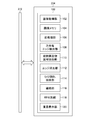
- FIG. 6 is a block diagram showing a system configuration of the crack detection apparatus 100 included in the image processing unit 334.
- the crack detection apparatus 100 includes an image acquisition unit 102, an image memory 104, a preprocessing unit 106, an edge detection unit 108 for each direction, a linear structure area extraction unit 110, an edge erasure unit 112, and a crack extraction.
- the image acquisition unit 102 acquires an image of the surface of the structure that is an object of crack detection via the system bus 312.
- the image acquired by the image acquisition unit 102 is stored in the image memory 104.
- the pre-processing unit 106 performs pre-processing such as noise removal on the surface image of the structure when detecting cracks.
- the edge detection unit for each direction 108 detects an edge existing in the preprocessed image, and generates an edge image indicating the detected edge.
- the linear structure area extraction unit 110 extracts an area where a linear structure exists on the surface of the structure based on the detected edge.
- the edge erasing unit 112 erases an edge corresponding to the linear structure from the edge image.
- deletion of edge refers to deletion of edge data corresponding to the linear structure from the edge image data.
- the corresponding edge may not be displayed, or the edge data may be deleted from the edge image data and the edge image may not be displayed when the edge image is displayed.
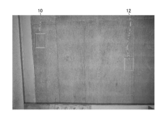
- FIG. 7 is a diagram showing the concrete surface of the floor board
- FIG. 8 is an enlarged view of the upper left portion 10 of FIG. 7
- FIG. 9 is an enlarged view of the right middle portion 12 of FIG.
- the linear structure area extraction unit 110 extracts an area where such a linear structure exists, and the edge elimination unit 112 erases an edge corresponding to the linear structure as a noise candidate.
- the crack extraction unit 114 detects a crack generated on the concrete surface from the edge remaining in the edge image from which the edge corresponding to the linear structure is deleted.
- the connecting unit 116 connects the detected cracks in the edge image.
- the FP discrimination unit 118 discriminates positive cracks and false positive cracks from cracks in the edge image.
- the superimposed display unit 120 (an example of a display control unit) superimposes positive cracks determined by the FP determination unit 118 on the original image acquired by the image acquisition unit 102 as a broken line, and displays the color of the display unit 326 via the system bus 312. This superimposed image is displayed on the LCD panel.
- FIG. 10 is a flowchart illustrating an example of a crack detection method in the crack detection apparatus 100.
- the user captures the concrete pillar 1 for detecting cracks with the camera 200, and transmits the captured image (an example of an image of the surface of the structure) to the computer 300.
- the computer 300 receives the captured image of the concrete pillar 1 via the mobile communication unit 318, the wireless LAN communication unit 320, the short-range wireless communication unit 322, or the wired communication unit 324.
- the image acquisition unit 102 of the crack detection apparatus 100 acquires the received image (step S ⁇ b> 2, an example of an image acquisition process), and stores the acquired image in the image memory 104.
- the preprocessing unit 106 performs preprocessing on the image (original image) stored in the image memory 104 (step S4). Specifically, first, only the region where the concrete surface is imaged is extracted from the image. Further, a blur process (smoothing process) is performed on the area where the concrete surface is imaged, and the density values before and after the blur process are compared. Here, of the pixels whose density value after the blur process is higher than the density value before the blur process, the top 10% pixels are extracted in descending order of the increase rate. By performing the preprocessing in this way, it is possible to reduce the subsequent calculation processing amount.
- a blur process smoothing process
- the edge detection unit for each direction performs edge detection processing for each direction at a plurality of spatial resolutions, and detects an edge for each thickness and for each direction from the image (step S6, an example of an edge detection process).
- edge detection processing for each direction a convolution operation using four-direction and three-layer Sobel filters is performed.
- the direction used as the reference for the edge detection process for each direction is determined within 0 to 180 degrees with reference to the horizontal direction of the input image.
- the direction of the bridge pillar or bridge may be used as a reference.
- FIGS. 11 to 14 respectively show the vertical direction, the direction rotated 45 degrees clockwise from the vertical direction (hereinafter referred to as the right oblique direction), and 45 degrees counterclockwise from the vertical direction.
- the figure which shows an example of the filter coefficient of Sobel filter 130-1, 130-2, 130-3, and 130-4 for detecting the direction of the rotation (henceforth a left diagonal direction) and the edge of a horizontal direction It is.
- the Sobel filters 130-1, 130-2, 130-3, and 130-4 are filters in which coefficients are respectively assigned to cells arranged in 3 rows ⁇ 3 columns, and the size of one cell is an image. It is the same as one pixel.
- the convolution operation using the Sobel filter associates the position of the pixel of interest of the image with the position of the center cell of the Sobel filter, and the filter corresponding to the pixel value of each pixel of interest and the surrounding pixels and the position of each pixel.
- the sum of the product with the coefficient is used as the edge intensity of the target pixel. Thereby, the intensity of the edge in each direction in the pixel of interest can be detected.
- FIG. 15 is a diagram illustrating an example of the surface image of the structure acquired by the image acquisition unit 102.
- FIG. 16 illustrates the edge detected from the image illustrated in FIG. It is a figure which shows the represented edge image.
- the size of each pixel of the edge image corresponds to the size of one pixel of the original image.
- FIG. 17 is a diagram showing edges for each direction detected using the Sobel filters 130-1, 130-2, 130-3, and 130-4 for the image shown in FIG. 15, and FIG. FIG. 18 is a partially enlarged view of FIG. 17.
- the vertical edge pixels are set to be upright squares.
- the pixel at the right diagonal edge is a triangle ( ⁇ )
- the pixel at the left diagonal edge is a diagonal square ( ⁇ ) with an upright square inclined by 45 degrees
- the pixel at the horizontal edge is Each is indicated by a circle ( ⁇ ).
- the edge for each direction is detected by the edge detection unit 108 for each direction in the vertical direction, the right diagonal direction, the left diagonal direction, and the horizontal direction.
- the edge detection unit 108 for each direction has cells of 3 rows ⁇ 3 columns, and includes four Sobel filters for detecting edges in the vertical direction, the right diagonal direction, the left diagonal direction, and the horizontal direction, respectively.
- Each cell has a Sobel filter with 4 pixels (2 vertical pixels x 2 horizontal pixels) and 3 rows by 3 columns of cells, and each has a vertical direction, right diagonal direction, and left Four Sobel filters for detecting diagonal edges and horizontal edges, each of which has a cell size of 9 pixels (3 vertical pixels ⁇ 3 horizontal pixels), It has.
- FIG. 20 is a diagram illustrating an example of the filter coefficient of the Sobel filter 132-1 for detecting the edge in the vertical direction in which the size of one cell is 4 pixels
- FIG. 21 illustrates the size of one cell. It is a figure which shows an example of the filter coefficient of the Sobel filter 134-1 which is for 9 pixels and detects the edge of a perpendicular direction.
- both the vertical size and horizontal size of the pixel of the image are doubled, that is, the vertical direction of the image. Both the direction resolution and the horizontal resolution need to be halved. When the resolution is halved, the pixel values of adjacent pixels may be averaged or a thinning process may be performed. Similarly, when performing a convolution operation using a Sobel filter whose size of one cell is 9 pixels, both the vertical resolution and the horizontal resolution of the image need to be 1 /.
- the edge detection unit for each direction 108 performs the convolution operation using the four-direction and three-layer Sobel filters, so that the edges in four directions and three kinds of thicknesses (three kinds of resolutions) are obtained. Detection is performed, and an edge image indicating the detected edge is generated. As a result, the crack detection process can be simplified and the amount of calculation processing can be reduced.
- the direction of edge detection is not limited to the four directions of the vertical direction, the right diagonal direction, the left diagonal direction, and the horizontal direction, and may be other directions, for example, eight directions including these directions.
- the edge detection by the edge detection unit 108 for each direction is not limited to processing using a Sobel filter, and for example, edge detection may be performed by processing using a Hessian matrix. In this case, an edge in an arbitrary direction can be detected.
- the spatial resolution for performing edge detection is not limited, and a spatial resolution suitable for the linear structure may be selected as appropriate.
- the linear structure area extracting unit 110 divides the image into a plurality of regions, and calculates the density of edges for each direction based on the edges detected in step S6 for the divided regions.
- the method of calculating the edge density in each direction is not limited, and may be calculated based on the number of edge pixels per unit area (an example of the density of the number of edge pixels), or the edge line per unit area. You may calculate based on the number of minutes (an example of the density of the line segment of an edge).
- the linear structure area extraction unit 110 extracts an area where the calculated edge density is higher than the first threshold from the plurality of areas of the image, and uses the extracted area as the existence area of the linear structure in that direction.
- FIG. 22 is a diagram illustrating an example of an image area on the horizontal axis and an edge density in the vertical direction of each area on the vertical axis.
- the regions in which the density of the edges in the vertical direction is higher than the first threshold are regions A 4 and A 5 . Therefore, the areas A 4 and A 5 are defined as the areas where the linear structures exist in the vertical direction.
- the edge erasure unit 112 corresponds to an edge in one of the directions where the edge density is higher than the first threshold, which is an edge existing in the existing area of the linear structure. It is determined that the edge is to be erased (step S8, an example of a noise erasing process).
- the edge pixel or the edge line segment in the direction in which the edge density is the highest among the directions in which the edge density is higher than the first threshold is erased from the edge image.
- the first threshold value a value corresponding to the density of a general linear structure may be used.
- edges due to linear structures existing in the image are eliminated.
- the edges in the specific direction may be deleted, or a plurality of edges whose density is higher than the first threshold value The edge in the direction may be erased.
- the linear structure corresponding to the edge of the noise candidate may be deleted from the original image, or may be deleted by processing in the FP determination unit 118 described later.
- FIG. 23 and 24 are diagrams showing an example of the edge 16 included in the edge image area 14.
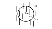
- the linear structure area extracting unit 110 determines that the region 14 is the vertical linear structure existing area.
- the edge erasing unit 112 recognizes and erases the edge 16 in the vertical direction from the region 14 from the image.
- the linear structure area extraction unit 110 determines that the area 14 is not an area where the linear structure exists. Authorize.
- the edge erasing unit 112 does not erase the edge 16L longer than the vertical length of the region 14 (an example of the third threshold value) even in the area where the linear structure exists. This is because the long edge 16L is not a linear structure but a crack or a straight line provided in the structure.
- the third threshold value a value exceeding the maximum length of the linear structure can be used.
- FIG. 25 is a diagram showing an edge image representing an edge for each direction detected in step S6, and FIG. 26 is a diagram in which the edge corresponding to the linear structure is erased in step S8 from the edge image shown in FIG. It is a figure which shows an edge image. As shown in FIG. 26, the noise of the edge image is reduced.
- the crack extraction unit 114 extracts an edge corresponding to a crack on the concrete surface from the edge remaining in the edge image from which the edge of the noise candidate is deleted (step S10, an example of a crack extraction process).
- the crack on the concrete surface has a narrow line width and a lower density value than the surrounding area.
- it has a characteristic that it has a length with respect to the background structure and has an indefinite shape locally but has a directionality globally.
- the crack extraction unit 114 extracts an edge corresponding to a crack having such characteristics from the edge image.
- the connecting part 116 connects edges corresponding to the cracks extracted by the crack extracting part 114 (step S12).
- one crack may be broken into a plurality of cracks.
- the connecting portion 116 connects edges corresponding to the broken cracks based on the direction and / or thickness of the cracks. The connection of cracks may be performed using a known method.
- the FP discriminating unit 118 discriminates the edge corresponding to the false positive crack existing in the edge image in which the edge corresponding to the crack is connected by the connecting unit 116, and determines the edge corresponding to the false positive crack. Delete from the edge image (step S14). What is necessary is just to perform a false positive discrimination
- the superimposing display unit 120 displays the original image on the touch panel display 302 (display unit 326), and superimposes and displays a broken line on the extracted cracked part (step S16).
- the broken line By displaying the broken line with respect to the cracked portion, it is possible to appropriately present the cracked portion to the user without misinterpreting the linear structure other than the crack and the region of dirt as a crack.
- the edge detection process for each direction is performed to calculate the density of edges for each direction, and the area where the calculated density is higher than the first threshold is the presence of the linear structure in that direction.
- an edge existing in the existing area and having an edge density higher than the first threshold in one direction is erased from the image, so that a linear structure such as a trowel mark is removed. It is possible to detect cracks that eliminate the influence.
- the crack detection method may be configured as a program for causing a computer to perform the above-described steps, and a non-temporary recording medium such as a CD-ROM (Compact Disk-Read Only Memory) storing the program may be configured. Is possible.
- a non-temporary recording medium such as a CD-ROM (Compact Disk-Read Only Memory) storing the program may be configured. Is possible.
- FIG. 27 is a block diagram illustrating a system configuration of a crack detection apparatus 140 according to the second embodiment provided in the image processing unit 334.
- the crack detection device 140 includes an edge detection unit 148 for each strength.
- the edge detector for each intensity 148 detects an edge for each intensity from the input image.
- FIG. 28 is a flowchart showing an example of a crack detection method in the crack detection device 140.
- symbol is attached
- the image acquisition unit 102 of the crack detection device 140 acquires the received image (step S2, an example of an image acquisition process), and the preprocessing unit 106 performs preprocessing on the original image stored in the image memory 104. (Step S4).
- the edge detection unit 148 performs edge detection processing at a plurality of spatial resolutions, detects edges for each thickness and intensity from the image, and generates an edge image (step S7, an example of an edge detection step) ). Edges for each intensity are detected by classifying them into, for example, an edge having a relatively high intensity, an edge having a relatively low intensity, and an edge having an intensity in between.
- the linear structure area extraction unit 110 calculates the density of edges for each intensity for a plurality of regions of the image based on the detected edges.
- the edge density for each intensity may also be calculated based on the number of edge pixels per unit area, or may be calculated based on the number of edge line segments per unit area.
- the linear structure area extraction unit 110 extracts an area where the calculated edge density is higher than the first threshold value from the plurality of areas of the image, and the extracted area is an area where the linear structure having the strength is present.
- FIG. 29 is a diagram illustrating an example of the density of edges having an intensity S with the horizontal axis representing the image area and the vertical axis representing each area.
- the regions where the density of edges of intensity S is higher than the first threshold are regions A 11 , A 12 , A 13 , and A 14 . Therefore, the areas A 11 , A 12 , A 13 , and A 14 are defined as areas where the linear structure having the strength S exists.
- the edge erasing unit 112 is an edge existing in the area where the linear structure exists, and corresponds to the linear structure with any one of the edges whose density is higher than the first threshold. It is determined that the edge is to be erased (step S9, an example of an edge erasing process).
- the edge pixel or edge line segment having the highest edge density among the intensities whose edge density is higher than the first threshold is erased from the edge image. Note that when the density of edges of a specific strength is higher than the fourth threshold value than the density of edges of other strengths, the edge of the specific strength may be deleted, or a plurality of edges having a density higher than the first threshold value may be deleted.
- the edge of the intensity of may be erased.
- An edge corresponding to a crack on the concrete surface is extracted by the crack extraction unit 114 from the edge image from which the edge corresponding to the linear structure is deleted (step S10, an example of a crack extraction process), and the connection unit 116 supports the crack.
- the edges to be connected are connected (step S12).
- the FP discriminating unit 118 discriminates the edge corresponding to the false positive crack existing in the edge image connected with the edge corresponding to the crack, and deletes the edge corresponding to the false positive crack from the edge image. (Step S14).
- the cracks are extracted from the original image, and the superimposed image display unit 120 displays the original image on the display unit 326 and superimposes it on the extracted cracks.
- the broken line is superimposed and displayed (step S16).
- the edge detection process is performed to calculate the density of the edge for each intensity, and the area where the calculated density is higher than the first threshold is set as the existence area of the linear structure having the intensity, Eliminating the influence of linear structures such as trowel traces by erasing any one of the edges that exist in the existing area and whose intensity is higher than the first threshold from the image. Cracks can be detected.
- strength which concerns on 2nd Embodiment is also possible.
- the edge detection process for each direction is performed to calculate the density of the edge for each direction, and the area where the calculated density is higher than the first threshold is the existing area of the linear structure in that direction. And deleting the edge in any one of the directions in which the edge density is higher than the first threshold value from the image, calculating the edge density for each intensity, and calculating the density to the second threshold value ( An area higher than the first threshold in the second embodiment) is an edge existing in the existing area, and the density of the edge is higher than the second threshold.
- a single intensity edge may be erased from the image.
- an edge whose edge density is higher than the first threshold value and whose edge density is higher than the second threshold value may be deleted from the image. What is necessary is just to use the value corresponding to the intensity
- the crack detection apparatus displays the edge determined to be the edge corresponding to the linear structure by the same direction line segment.
- FIG. 30 shows the same direction on the touch panel display 302 (see FIG. 2) with the edges detected by the edge detector for each direction 108 (see FIG. 6) or the edge detector for each intensity 148 (see FIG. 27) superimposed on the original image.
- the line segments corresponding to each edge are classified and displayed as similar direction line segment groups for each similar direction, the same direction line segment group 18 indicated by a solid line, the same direction line segment group 20 indicated by a broken line, and The same direction line segment group 22 shown with the dashed-dotted line is displayed.
- the colors may be displayed differently.
- the user can erase the edge corresponding to the linear structure by looking at the display on the touch panel display 302.
- the edge to be erased may be selected by inputting the line type of the same direction line segment corresponding to the edge to be erased, or may be selected by surrounding the area including the edge to be erased with a touch operation.
- the edge corresponding to the same direction line segment group 20 included in the selection area 24 selected by the touch operation is deleted.
- the noise corresponding to the linear structure can be appropriately removed by allowing the user to manually select the edges displayed as the same-direction line segment group.
Landscapes
- Physics & Mathematics (AREA)
- General Physics & Mathematics (AREA)
- Engineering & Computer Science (AREA)
- Theoretical Computer Science (AREA)
- Health & Medical Sciences (AREA)
- Life Sciences & Earth Sciences (AREA)
- Chemical & Material Sciences (AREA)
- Analytical Chemistry (AREA)
- Biochemistry (AREA)
- General Health & Medical Sciences (AREA)
- Immunology (AREA)
- Pathology (AREA)
- Image Analysis (AREA)
- Investigating Materials By The Use Of Optical Means Adapted For Particular Applications (AREA)
- Image Processing (AREA)
Abstract
構造物の表面に線状構造物が密に存在する場合であってもひび割れを検出することができるひび割れ検出装置、ひび割れ検出方法及びプログラムを提供する。構造物の表面の画像を取得する画像取得部と、構造物の表面の画像から方向毎のエッジを検出するエッジ検出部と、画像の複数の領域について方向毎のエッジの密度を算出し、エッジの密度が第1閾値より高い領域に存在するエッジであって、エッジの密度が第1閾値より高い方向のうちいずれか1つの方向のエッジを領域から消去するエッジ消去部と、エッジから構造物の表面のひび割れを抽出するひび割れ抽出部と、を備えたひび割れ検出装置によって上記課題を解決する。
Description
本発明は、ひび割れ検出装置、ひび割れ検出方法及びプログラムに関し、特に構造物の表面の画像からひび割れを容易に検出するひび割れ検出装置、ひび割れ検出方法及びプログラムに関する。
近年、社会的インフラストラクチャ(インフラ)の老朽化が問題となっている。インフラのメンテナンスの効率を上げるために、インフラを構成する建造物の表面を撮像した点検用画像を画像解析することにより、ひび割れを検出する技術が知られている。
特許文献1には、ウェーブレット変換を適用したひび割れ検出方法が記載されている。この技術によれば、撮像されたコンクリート表面の汚れ又は照明条件などによってひび割れの検出が困難な場合においても、簡易に高精度のひび割れ検出を行うことができる。
また、特許文献2には、コンクリート構造物の色と同じ色であって、コンクリート構造物のテクスチャと同じテクスチャの画素をコンクリート候補領域として抽出する技術が記載されている。この技術によれば、コンクリート構造物の撮像画像からコンクリート面以外の背景及び/又は障害物を除去することが可能となる。
施工作業等の要因により、構造物の表面にこて跡のような線状構造物が密に存在することがある。このような線状構造物が表面に存在すると、表面の画像からひび割れを検出する際に線状構造物とひび割れとの判別が困難となり、ひび割れの検出ができないという問題点があった。特許文献1及び特許文献2に記載された技術においても、この問題点を解決することはできない。
本発明はこのような事情に鑑みてなされたもので、構造物の表面に線状構造物が密に存在する場合であってもひび割れを検出することができるひび割れ検出装置、ひび割れ検出方法及びプログラムを提供することを目的とする。
上記目的を達成するためにひび割れ検出装置の一の態様は、構造物の表面の画像を取得する画像取得部と、構造物の表面の画像から方向毎のエッジを検出するエッジ検出部と、画像の複数の領域について方向毎のエッジの密度を算出し、エッジの密度が第1閾値より高い領域に存在するエッジであって、エッジの密度が第1閾値より高い方向のうちいずれか1つの方向のエッジを領域から消去するエッジ消去部と、エッジから構造物の表面のひび割れを抽出するひび割れ抽出部と、を備えた。
本態様によれば、構造物の表面の画像から方向毎のエッジを検出し、画像の複数の領域について方向毎のエッジの密度を算出し、エッジの密度が第1閾値より高い領域に存在するエッジであって、エッジの密度が第1閾値より高い方向のうちいずれか1つの方向のエッジを消去し、エッジから構造物の表面のひび割れを抽出するようにしたので、構造物の表面に線状構造物が密に存在する場合であってもひび割れを検出することができる。
エッジ消去部は、エッジの密度が第1閾値より高い領域に存在するエッジであって、エッジの密度が最も高い方向のエッジを領域から消去することが好ましい。これにより、線状構造物によるノイズを適切に排除することができる。
エッジ検出部は、構造物の表面の画像から強度毎のエッジを検出し、エッジ消去部は、画像の複数の領域について強度毎のエッジの密度を算出し、エッジの密度が第2閾値より高い領域に存在するエッジであって、エッジの密度が第2閾値より高い強度のうちいずれか1つの強度のエッジを領域から消去することが好ましい。これにより、線状構造物によるノイズを適切に排除することができる。
上記目的を達成するためにひび割れ検出装置の一の態様は、構造物の表面の画像を取得する画像取得部と、構造物の表面の画像から強度毎のエッジを検出するエッジ検出部と、画像の複数の領域について強度毎のエッジの密度を算出し、エッジの密度が第1閾値より高い領域に存在するエッジであって、エッジの密度が第1閾値より高い強度のうちいずれか1つの強度のエッジを領域から消去するエッジ消去部と、エッジから構造物の表面のひび割れを抽出するひび割れ抽出部と、を備えた。
本態様によれば、構造物の表面の画像から強度毎のエッジを検出し、画像の複数の領域について強度毎のエッジの密度を算出し、エッジの密度が第1閾値より高い領域に存在するエッジであって、エッジの密度が第1閾値より高い強度のうちいずれか1つの強度のエッジを消去し、エッジから構造物の表面のひび割れを抽出するようにしたので、構造物の表面に線状構造物が密に存在する場合であってもひび割れを検出することができる。
エッジ消去部は、エッジの密度が第1閾値より高い領域に存在するエッジであって、エッジの密度が最も高い強度のエッジを領域から消去することが好ましい。これにより、線状構造物によるノイズを適切に排除することができる。
エッジ検出部は、複数の空間解像度でエッジを検出することが好ましい。これにより、線状構造物の太さにかかわらず線状構造物によるノイズを適切に排除することができる。
エッジ消去部は、エッジのピクセル数の密度を算出することが好ましい。また、エッジ消去部は、エッジの線分数の密度を算出してもよい。これにより、エッジの密度を適切に算出することができる。
エッジ消去部は、第3閾値より長さの長いエッジを領域から消去しないことが好ましい。これにより、線状構造物によるノイズのみを適切に排除することができる。
検出したエッジを表示部に表示する表示制御部と、表示部に表示されたエッジのうち、領域から消去するエッジをユーザに選択させる入力部と、を備え、エッジ消去部は、選択されたエッジを領域から消去することが好ましい。これにより、線状構造物によるノイズのみを適切に排除することができる。
上記目的を達成するためにひび割れ検出方法の一の態様は、構造物の表面の画像を取得する画像取得工程と、構造物の表面の画像から方向毎のエッジを検出するエッジ検出工程と、画像の複数の領域について方向毎のエッジの密度を算出し、エッジの密度が第1閾値より高い領域に存在するエッジであって、エッジの密度が第1閾値より高い方向のうちいずれか1つの方向のエッジを領域から消去するエッジ消去工程と、エッジから構造物の表面のひび割れを抽出するひび割れ抽出工程と、を備えた。
本態様によれば、構造物の表面の画像から方向毎のエッジを検出し、画像の複数の領域について方向毎のエッジの密度を算出し、エッジの密度が第1閾値より高い領域に存在するエッジであって、エッジの密度が第1閾値より高い方向のうちいずれか1つの方向のエッジを領域から消去し、エッジから構造物の表面のひび割れを抽出するようにしたので、構造物の表面に線状構造物が密に存在する場合であってもひび割れを検出することができる。
上記目的を達成するためにひび割れ検出方法の一の態様は、構造物の表面の画像を取得する画像取得工程と、構造物の表面の画像から強度毎のエッジを検出するエッジ検出工程と、画像の複数の領域について強度毎のエッジの密度を算出し、エッジの密度が第1閾値より高い領域に存在するエッジであって、エッジの密度が第1閾値より高い強度のうちいずれか1つの強度のエッジを領域から消去するエッジ消去工程と、エッジから構造物の表面のひび割れを抽出するひび割れ抽出工程と、を備えた。
本態様によれば、構造物の表面の画像から強度毎のエッジを検出し、画像の複数の領域について強度毎のエッジの密度を算出し、エッジの密度が第1閾値より高い領域に存在するエッジであって、エッジの密度が第1閾値より高い強度のうちいずれか1つの強度のエッジを領域から消去し、エッジから構造物の表面のひび割れを抽出するようにしたので、構造物の表面に線状構造物が密に存在する場合であってもひび割れを検出することができる。
ひび割れ検出方法をコンピュータに実行させるプログラムも上記目的を達成するための一の態様に含まれる。
本発明によれば、構造物の表面に線状構造物が密に存在する場合であってもひび割れを検出することができる。
以下、添付図面に従って本発明の好ましい実施の形態について説明する。
<ひび割れ検出装置の構成>
図1は、本実施形態に係るひび割れ検出装置を含むコンピュータの全体構成図である。
図1は、本実施形態に係るひび割れ検出装置を含むコンピュータの全体構成図である。
コンピュータ300は、ひび割れ検出装置100(図6参照)を内蔵し、カメラ200によって撮像されたコンクリート柱1の表面の画像を取得し、取得した画像を画像解析することにより、コンクリート柱1に発生したひび割れ2の検出を行う。
コンクリート柱1は、コンピュータ300により行われるひび割れ検出の対象物である。なお、ひび割れ検出の対象物としてはコンクリート柱に限定されず、金属構造物又は木造物等の壁又は床等(構造物の一例)を対象物とすることができる。また、ひび割れの他、遊離石灰等の損傷を検出することができる。
コンピュータ300は、ひび割れ検出の対象物の画像をカメラ200から取得する。カメラ200は、コンクリート柱1の表面(構造物の表面の一例)を撮像し、撮像した画像をコンピュータ300に無線又は有線で送信する。なお、コンピュータ300は、後述する内蔵カメラ305(図3参照)においてひび割れ検出の対象物を撮像することで画像を取得してもよいし、外部接続端子306(図2参照)に接続したUSB(Universal Serial Bus)メモリ等の記録媒体から読み出すことで画像を取得してもよい。
図2は、コンピュータ300の正面斜視図であり、図3は背面斜視図である。図2及び図3に示すように、コンピュータ300は、タブレット型のコンピュータで構成される。コンピュータ300は、矩形の輪郭を有する平板状の筐体301を備え、その筐体301にタッチパネルディスプレイ302、操作ボタン303、スピーカ304、内蔵カメラ305、及び外部接続端子306等を備えて構成される。
図4は、コンピュータ300のシステム構成を示すブロック図である。同図に示すように、コンピュータ300は、コンピュータ300の全体の動作を制御するCPU(Central Processing Unit)310を備え、このCPU310にシステムバス312を介して、メインメモリ314、不揮発性メモリ316、モバイル通信部318、無線LAN(Local Area Network)通信部320、近距離無線通信部322、有線通信部324、表示部326、入力部328、キー入力部330、音声処理部332、及び画像処理部334等が接続されて構成される。
CPU310は、不揮発性メモリ316に記憶された動作プログラム(OS(Operating System)、及びOS上で動作するアプリケーションプログラム)及び定型データ等を読み出し、メインメモリ314に展開して動作プログラムを実行することにより、このコンピュータ全体の動作を制御する制御部として機能する。
メインメモリ314は、例えば、RAM(Random Access Memory)で構成され、CPU310のワークメモリとして機能する。
不揮発性メモリ316は、例えば、フラッシュEEPROM(Electrically Erasable Programmable Read Only Memory)で構成され、前述した動作プログラム及び各種定型データを記憶する。また、不揮発性メモリ316は、コンピュータ300の記憶部として機能し、各種データを記憶する。
モバイル通信部318は、IMT-2000(International Mobile Telecommunication 2000)規格に準拠した第3世代移動通信システム及びIMT-Advanced(International Mobile Telecommunications-Advanced)規格に準拠した第4世代移動通信システムに基づき、アンテナ318Aを介して最寄りの図示しない基地局との間でデータの送受信を実行する。
無線LAN通信部320は、アンテナ320Aを介して、無線LANアクセスポイント又は無線LAN通信が可能な外部機器との間でIEEE(Institute of Electrical and Electronics Engineers)802.11a/b/g/n規格等の無線LAN通信規格に従った無線LAN通信を行う。
近距離無線通信部322は、アンテナ322Aを介して、例えばクラス2(半径約10m以内)の範囲にある他のBluetooth(登録商標)規格の機器との間で通信を行う。
有線通信部324は、外部接続端子306を介して不図示のケーブルで接続された外部機器との間で所定の通信規格に従った通信を行う。
表示部326は、タッチパネルディスプレイ302のディスプレイ部分を構成するカラーLCD(Liquid Crystal Display)パネルとその駆動回路とで構成され、カラーLCDパネルに各種画像を表示する。
入力部328は、タッチパネルディスプレイ302のタッチパネル部分を構成する。入力部328は、透明電極を用いてカラーLCDパネルと一体的に構成される。入力部328は、ユーザのタッチ操作に対応した2次元の位置座標情報を生成して出力する。
キー入力部330は、コンピュータ300の筐体301に備えられた複数の操作ボタン303と、その駆動回路と、で構成される。
音声処理部332は、システムバス312を介して与えられるデジタル音声データをアナログ化する。アナログ化された音声信号は、スピーカ304から再生出力される。
画像処理部334は、撮像レンズ及びイメージセンサを備えた内蔵カメラ305から出力されるアナログの画像信号をデジタル化し、所要の信号処理を施して出力する。また、画像処理部334は、後述するひび割れ検出装置100(図6参照)を備えている。
<ひび割れ検出装置>
ひび割れ検出装置100は、ひび割れ検出の対象物である構造物の表面の画像を画像解析し、構造物の表面のひび割れを検出する。
ひび割れ検出装置100は、ひび割れ検出の対象物である構造物の表面の画像を画像解析し、構造物の表面のひび割れを検出する。
図5は、構造物の表面の画像の一例である。構造物の表面に発生したひび割れの画像上の表現には、(1)線幅が細く、周辺より濃度値が低い、(2)背景構造物に対して一定以上の長さがある、(3)局所的には不定形状だが、大局的には方向性を持つ、という特徴を有している。
また、このようなひび割れを画像から検出する際の主要な困難点として、(1)1本のひび割れが複数に断線されており、完全な検出が容易でない、(2)細い、即ちコントラストが低いひび割れを検出するため、背景中に類似する構造物も同時に検出されやすく、断続的なひび割れと多数の偽陽性(FP、False-Positive)との区別が容易でない、という点が挙げられる。
本実施形態に係るひび割れ検出装置100は、特に構造物の表面にこて跡のような線状構造物が密に存在する場合に、線状構造物を排除してひび割れを検出する。
図6は、画像処理部334が備えるひび割れ検出装置100のシステム構成を示すブロック図である。同図に示すように、ひび割れ検出装置100は、画像取得部102、画像メモリ104、前処理部106、方向毎エッジ検出部108、線状構造物区域抽出部110、エッジ消去部112、ひび割れ抽出部114、連結部116、FP判別部118、及び重畳表示部120等を備えている。
画像取得部102は、システムバス312を介してひび割れ検出の対象物である構造物の表面の画像を取得する。画像取得部102において取得した画像は、画像メモリ104に記憶される。
前処理部106は、ひび割れ検出を行うにあたって構造物の表面の画像にノイズ除去等の前処理を施す。方向毎エッジ検出部108は、前処理が施された画像内に存在するエッジを検出し、検出したエッジを示すエッジ画像を生成する。
線状構造物区域抽出部110は、検出されたエッジに基づいて構造物の表面の線状構造物の存在する区域を抽出する。エッジ消去部112は、エッジ画像から線状構造物に対応するエッジを消去する。なお、ここでいうエッジの消去とは、エッジ画像のデータから線状構造物に対応するエッジのデータを削除することであるが、エッジ画像のデータは加工せずにエッジ画像を表示する際に該当するエッジを表示しないことであってもよいし、エッジ画像のデータから該当するエッジのデータを削除し、かつエッジ画像を表示する際にそのエッジを表示しないことであってもよい。
図7は床板のコンクリート表面を示す図であり、図8は図7の左上部10を拡大した図であり、図9は図7の右中部12を拡大した図である。図8及び図9に示すように、このコンクリート表面には、図中上下に延びるこて跡の線状構造物が存在する。線状構造物区域抽出部110はこのような線状構造物の存在する区域を抽出し、エッジ消去部112は線状構造物に対応するエッジをノイズ候補として消去する。
ひび割れ抽出部114は、線状構造物に対応するエッジが消去されたエッジ画像に残存するエッジからコンクリート表面に発生しているひび割れを検出する。
連結部116は、検出したひび割れをエッジ画像において連結する。FP判別部118は、エッジ画像内のひび割れから陽性のひび割れと偽陽性のひび割れとを判別する。重畳表示部120(表示制御部の一例)は、画像取得部102が取得した元画像にFP判別部118が判別した陽性のひび割れを折れ線として重畳し、システムバス312を介して表示部326のカラーLCDパネルにこの重畳画像を表示させる。
<ひび割れ検出方法>
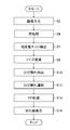
図10は、ひび割れ検出装置100におけるひび割れ検出方法の一例を示すフローチャートである。
図10は、ひび割れ検出装置100におけるひび割れ検出方法の一例を示すフローチャートである。
まず、ユーザは、ひび割れ検出を行うコンクリート柱1をカメラ200によって撮像し、撮像した画像(構造物の表面の画像の一例)をコンピュータ300に送信する。コンピュータ300は、モバイル通信部318、無線LAN通信部320、近距離無線通信部322、又は有線通信部324を介して、コンクリート柱1の撮像画像を受信する。ひび割れ検出装置100の画像取得部102は、受信した画像を取得し(ステップS2、画像取得工程の一例)、取得した画像を画像メモリ104に記憶させる。
次に、前処理部106において、画像メモリ104に記憶された画像(元画像)に対して前処理を施す(ステップS4)。具体的には、まず、画像の中からコンクリート表面が撮像された領域のみを抽出する。さらにコンクリート表面が撮像された領域についてぼけ処理(平滑化処理)を行い、ぼけ処理前後の濃度値を比較する。ここでは、ぼけ処理後の濃度値がぼけ処理前の濃度値よりも上昇するピクセルのうち、上昇率が大きい方から上位1割のピクセルを抽出する。このように前処理を施すことで、その後の計算処理量を低減することができる。
続いて、方向毎エッジ検出部108において、複数の空間解像度において方向毎のエッジ検出処理を施し、画像から太さ毎かつ方向毎のエッジを検出する(ステップS6、エッジ検出工程の一例)。ここでは、方向毎のエッジ検出処理の一例として、4方向及び3層のソーベル(Sobel)フィルタを用いた畳み込み演算を行う。方向毎エッジ検出処理の基準とする方向は、入力画像の横方向を基準し、0~180度内で決定する。なお、橋梁の柱や橋梁の方向を基準にしてもよい。
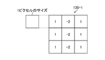
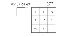
図11~図14は、方向毎エッジ検出部108が備えた、それぞれ垂直方向、垂直方向から右回りに45度回転した方向(以下、右斜め方向と呼ぶ)、垂直方向から左回りに45度回転した方向(以下、左斜め方向と呼ぶ)、及び水平方向のエッジを検出するためのソーベルフィルタ130-1、130-2、130-3、及び130-4のフィルタ係数の一例を示す図である。ソーベルフィルタ130-1、130-2、130-3、及び130-4は、3行×3列に配列されたセルにそれぞれ係数が割り当てられたフィルタであり、1つのセルの大きさは画像の1ピクセルと同様である。
ソーベルフィルタを用いた畳み込み演算は、画像の注目ピクセルの位置とソーベルフィルタの中心セルの位置とを対応させ、注目ピクセル及びその周辺の各ピクセルの画素値と各ピクセルの位置に対応するフィルタ係数との積の和を注目ピクセルのエッジの強度とする。これにより、注目ピクセルにおける各方向のエッジの強度を検出することができる。
図15は、画像取得部102が取得した構造物の表面の画像の一例を示す図であり、図16は、図15に示す画像から検出されたエッジを、エッジの強度が高いほど輝度を高く表したエッジ画像を示す図である。このエッジ画像の各ピクセルの大きさは、元画像の1ピクセルの大きさに相当する。
また、図17は、図15に示す画像についてソーベルフィルタ130-1、130-2、130-3、及び130-4を用いて検出した方向毎のエッジを示す図であり、図18は、図17の一部拡大図である。ここでは、画像の横方向を基準として垂直方向、右斜め方向、左斜め方向、及び水平方向の4方向のエッジについて、図19の凡例に示すように、垂直方向のエッジのピクセルを正立正方形(□)で、右斜め方向のエッジのピクセルを三角形(△)で、左斜め方向のエッジのピクセルを45度だけ正立正方形を傾けた斜め正方形(◇)で、水平方向のエッジのピクセルを円形(○)で、それぞれ示している。このように、方向毎エッジ検出部108により、垂直方向、右斜め方向、左斜め方向、及び水平方向の方向毎のエッジが検出される。
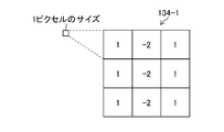
さらに、方向毎エッジ検出部108は、3行×3列のセルを有し、それぞれ垂直方向、右斜め方向、左斜め方向、及び水平方向のエッジを検出するための4つのソーベルフィルタであって、それぞれ1つのセルの大きさが4ピクセル分(縦2ピクセル分×横2ピクセル分)のソーベルフィルタと、3行×3列のセルを有し、それぞれ垂直方向、右斜め方向、左斜め方向、及び水平方向のエッジを検出するための4つのソーベルフィルタであって、それぞれ1つのセルの大きさが9ピクセル分(縦3ピクセル分×横3ピクセル分)のソーベルフィルタと、を備えている。図20は、1つのセルの大きさが4ピクセル分であり、垂直方向のエッジを検出するソーベルフィルタ132-1のフィルタ係数の一例を示す図であり、図21は、1つのセルの大きさが9ピクセル分であり、垂直方向のエッジを検出するソーベルフィルタ134-1のフィルタ係数の一例を示す図である。
1つのセルの大きさが4ピクセル分のソーベルフィルタを用いた畳み込み演算を行うためには、画像のピクセルの垂直方向の大きさ及び水平方向の大きさをともに2倍に、即ち画像の垂直方向の解像度及び水平方向の解像度をともに1/2にする必要がある。解像度を1/2にする際には、それぞれ隣り合うピクセルの画素値を平均してもよいし、間引き処理を行ってもよい。1つのセルの大きさが9ピクセル分のソーベルフィルタを用いた畳み込み演算を行う場合も同様に、画像の垂直方向の解像度及び水平方向の解像度をともに1/3にする必要がある。
このように、方向毎エッジ検出部108は、4方向及び3層のソーベル(Sobel)フィルタを用いた畳み込み演算を行うことで、4つの方向及び3種類の太さ(3種類の解像度)のエッジ検出を行い、検出したエッジを示すエッジ画像を生成する。これにより、ひび割れ検出処理を簡易にし、計算処理量を低減することができる。
なお、エッジ検出の方向は、垂直方向、右斜め方向、左斜め方向、及び水平方向の4方向に限定されず、他の方向でもよいし、これらの方向を含む例えば8方向でもよい。また、方向毎エッジ検出部108によるエッジ検出はソーベルフィルタを用いた処理に限定されず、例えばヘッセ行列(Hessian matrix)を用いた処理によってエッジ検出を行ってもよい。この場合は、任意の方向のエッジを検出することができる。
また、エッジ検出を行う空間解像度も限定されず、線状構造物に適した空間解像度を適宜選択すればよい。
次に、線状構造物区域抽出部110は、画像を複数の領域に分割し、分割した複数の領域について、ステップS6において検出したエッジに基づいて方向毎のエッジの密度を算出する。この方向毎のエッジの密度の算出方法は限定されず、単位面積当たりのエッジのピクセル数(エッジのピクセル数の密度の一例)に基づいて算出してもよいし、単位面積当たりのエッジの線分の本数(エッジの線分数の密度の一例)に基づいて算出してもよい。
さらに、線状構造物区域抽出部110は、画像の複数の領域の中から算出したエッジの密度が第1閾値より高い領域を抽出し、抽出した領域をその方向の線状構造物の存在区域とする。図22は、横軸に画像の領域、縦軸に各領域の垂直方向のエッジの密度の一例を示す図である。図22に示す例では、垂直方向のエッジの密度が第1閾値より高い領域は領域A4及びA5である。したがって、領域A4及びA5を垂直方向の線状構造物の存在区域とする。
そして、エッジ消去部112は、線状構造物の存在区域に存在するエッジであって、エッジの密度が第1閾値より高い方向のうちいずれか1つの方向のエッジを、線状構造物に対応するエッジであると判断して消去する(ステップS8、ノイズ消去工程の一例)。ここでは、エッジの密度が第1閾値より高い方向のうちエッジの密度が最も高い方向のエッジのピクセル、又はエッジの線分をエッジ画像から消去する。第1閾値としては、一般的な線状構造物の密度に対応する値を使用すればよい。
このように、画像からノイズの候補であるエッジを消去することで、画像内に存在する線状構造物によるエッジが排除される。なお、特定の方向のエッジの密度が他の方向のエッジの密度より第4閾値より高い場合に、その特定の方向のエッジを消去してもよいし、エッジの密度が第1閾値より高い複数の方向のエッジを消去してもよい。また、元画像からノイズの候補のエッジに対応する線状構造物を消去してもよいし、後述するFP判別部118における処理で消去してもよい。
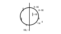
図23及び図24は、ともにエッジ画像の領域14に含まれるエッジ16の一例を示す図である。領域14の垂直方向のエッジ16の密度が第1閾値より高い(図23)と判断されると、線状構造物区域抽出部110は、領域14を垂直方向の線状構造物の存在区域と認定し、エッジ消去部112は、領域14から垂直方向のエッジ16を画像から消去する。一方、領域14の垂直方向のエッジ16の密度が第1閾値未満(図24)と判断されると、線状構造物区域抽出部110は、領域14を線状構造物の存在区域ではないと認定する。
なお、エッジ消去部112は、領域14の垂直方向長さ(第3閾値の一例)より長いエッジ16Lについては、線状構造物の存在区域内であっても消去しない。これは、長いエッジ16Lは線状構造物ではなく、ひび割れ又は構造物に設けられた直線であると考えられるためである。第3閾値としては、線状構造物の長さの最大値を超える値を用いることができる。
図25は、ステップS6において検出された方向毎のエッジを表すエッジ画像を示す図であり、図26は、図25に示すエッジ画像からステップS8において線状構造物に対応するエッジが消去されたエッジ画像を示す図である。図26に示すように、エッジ画像のノイズが低減される。
ひび割れ抽出部114は、このノイズ候補のエッジが消去されたエッジ画像に残存するエッジから、コンクリート表面のひび割れに対応するエッジを抽出する(ステップS10、ひび割れ抽出工程の一例)。前述したように、コンクリート表面のひび割れは線幅が細く周辺より濃度値が低い。また、背景構造物に対して長さがあり、局所的には不定形状だが、大局的には方向性を持つという特性を有している。ひび割れ抽出部114は、エッジ画像からこのような特性を有するひび割れに対応するエッジを抽出する。
さらに、連結部116は、ひび割れ抽出部114によって抽出されたひび割れに対応するエッジを連結する(ステップS12)。ひび割れ抽出部114によって抽出されたひび割れは、1本のひび割れが複数のひび割れに断線されている場合がある。連結部116は、ひび割れの方向及び/又は太さに基づいて、断線されたひび割れに対応するエッジを連結する。ひび割れの連結については、公知の方法を用いて行えばよい。
続いて、FP判別部118は、連結部116によってひび割れに対応するエッジが連結されたエッジ画像の中に存在する偽陽性のひび割れに対応するエッジを判別し、偽陽性のひび割れに対応するエッジをエッジ画像から削除する(ステップS14)。偽陽性の判別についても、公知の方法を用いて行えばよい。
このように、エッジ画像にはひび割れに対応するエッジのみが残る。エッジ画像に残ったひび割れに対応するエッジに基づいて、元画像からひび割れを抽出する。
最後に、重畳表示部120は、タッチパネルディスプレイ302(表示部326)に元画像を表示するとともに、抽出されたひび割れの部分に重ねて折れ線を重畳表示する(ステップS16)。ひび割れの部分に対して折れ線表示を行うことで、ひび割れ以外の線状構造物及び汚れの領域をひび割れと誤解させることなく、ユーザにひび割れ箇所を適切に提示することができる。
このように、本実施形態によれば、方向毎のエッジ検出処理を施して方向毎のエッジの密度を算出し、算出した密度が第1閾値より高い領域をその方向の線状構造物の存在区域として、存在区域に存在するエッジであって、エッジの密度が第1閾値より高い方向のうちいずれか1つの方向のエッジを画像から消去することで、こて跡等の線状構造物の影響を排除したひび割れの検出を行うことができる。
ひび割れ検出方法は、コンピュータに上記の各工程を実現させるためのプログラムとして構成し、当該プログラムを記憶したCD-ROM(Compact Disk-Read Only Memory)等の非一時的な記録媒体を構成することも可能である。
<第2の実施形態>
図27は、画像処理部334が備える第2の実施形態に係るひび割れ検出装置140のシステム構成を示すブロック図である。なお、図6に示すひび割れ検出装置100と共通する部分には同一の符号を付し、その詳細な説明は省略する。ひび割れ検出装置140は、強度毎エッジ検出部148を備えている。強度毎エッジ検出部148は、入力された画像から強度毎のエッジを検出する。
図27は、画像処理部334が備える第2の実施形態に係るひび割れ検出装置140のシステム構成を示すブロック図である。なお、図6に示すひび割れ検出装置100と共通する部分には同一の符号を付し、その詳細な説明は省略する。ひび割れ検出装置140は、強度毎エッジ検出部148を備えている。強度毎エッジ検出部148は、入力された画像から強度毎のエッジを検出する。
図28は、ひび割れ検出装置140におけるひび割れ検出方法の一例を示すフローチャートである。なお、図10に示すフローチャートと共通する部分には同一の符号を付し、その詳細な説明は省略する。
ひび割れ検出装置140の画像取得部102は、受信した画像を取得し(ステップS2、画像取得工程の一例)、前処理部106において、画像メモリ104に記憶された元画像に対して前処理を施す(ステップS4)。
続いて、強度毎エッジ検出部148において、複数の空間解像度でエッジ検出処理を施し、画像から太さ毎かつ強度毎のエッジを検出し、エッジ画像を生成する(ステップS7、エッジ検出工程の一例)。強度毎のエッジは、例えば強度が相対的に高いエッジ、強度が相対的に低いエッジ、及び強度がその間のエッジ等に分類して検出する。
次に、線状構造物区域抽出部110は、検出したエッジに基づいて、画像の複数の領域について強度毎のエッジの密度を算出する。強度毎のエッジの密度についても、単位面積当たりのエッジのピクセル数に基づいて算出してもよいし、単位面積当たりのエッジの線分の本数に基づいて算出してもよい。
さらに、線状構造物区域抽出部110は、画像の複数の領域の中から算出したエッジの密度が第1閾値より高い領域を抽出し、抽出した領域をその強度の線状構造物の存在区域とする。図29は、横軸に画像の領域、縦軸に各領域のある強度Sのエッジの密度の一例を示す図である。図29に示す例では、強度Sのエッジの密度が第1閾値より高い領域は領域A11、A12、A13、及びA14である。したがって、領域A11、A12、A13、及びA14を強度Sの線状構造物の存在区域とする。
そして、エッジ消去部112は、線状構造物の存在区域に存在するエッジであって、エッジの密度が第1閾値より高い強度のうちいずれか1つの強度のエッジを、線状構造物に対応するエッジであると判断して消去する(ステップS9、エッジ消去工程の一例)。ここでは、エッジの密度が第1閾値より高い強度のうちエッジの密度が最も高い強度のエッジのピクセル、又はエッジの線分をエッジ画像から消去する。なお、特定の強度のエッジの密度が他の強度のエッジの密度より第4閾値より高い場合に、その特定の強度のエッジを消去してもよいし、エッジの密度が第1閾値より高い複数の強度のエッジを消去してもよい。
線状構造物に対応するエッジが消去されたエッジ画像から、ひび割れ抽出部114においてコンクリート表面のひび割れに対応するエッジを抽出し(ステップS10、ひび割れ抽出工程の一例)、連結部116においてひび割れに対応するエッジを連結する(ステップS12)。
さらに、FP判別部118において、ひび割れに対応するエッジが連結されたエッジ画像の中に存在する偽陽性のひび割れに対応するエッジを判別し、偽陽性のひび割れに対応するエッジをエッジ画像から削除する(ステップS14)。
最後に、エッジ画像に残ったひび割れに対応するエッジに基づいて、元画像からひび割れを抽出し、重畳表示部120において、表示部326に元画像を表示するとともに、抽出されたひび割れの部分に重ねて折れ線を重畳表示する(ステップS16)。
このように、本実施形態によれば、エッジ検出処理を施して強度毎のエッジの密度を算出し、算出した密度が第1閾値より高い領域をその強度の線状構造物の存在区域として、存在区域に存在するエッジであって、エッジの密度が第1閾値より高い強度のうちいずれか1つの強度のエッジを画像から消去することで、こて跡等の線状構造物の影響を排除したひび割れの検出を行うことができる。
なお、第1の実施形態に係る方向毎のエッジの密度と第2の実施形態に係る強度毎のエッジの密度とを組み合わせる態様も可能である。この場合は、方向毎のエッジ検出処理を施して方向毎のエッジの密度を算出し、算出した密度が第1閾値より高い領域をその方向の線状構造物の存在区域として、存在区域に存在するエッジであって、エッジの密度が第1閾値より高い方向のうちいずれか1つの方向のエッジを画像から消去するとともに、強度毎のエッジの密度を算出し、算出した密度が第2閾値(第2の実施形態における第1閾値)より高い領域をその強度の線状構造物の存在区域として、存在区域に存在するエッジであって、エッジの密度が第2閾値より高い強度のうちいずれか1つの強度のエッジを画像から消去すればよい。また、エッジの密度が第1閾値より高い方向のエッジであって、かつエッジの密度が第2閾値より高い強度のエッジを画像から消去してもよい。第2閾値としては、一般的な線状構造物の強度に対応する値を使用すればよい。
<第3の実施形態>
第3の実施形態に係るひび割れ検出装置は、線状構造物に対応するエッジと判断されたエッジを同一方向線分表示する。
第3の実施形態に係るひび割れ検出装置は、線状構造物に対応するエッジと判断されたエッジを同一方向線分表示する。
図30は、方向毎エッジ検出部108(図6参照)又は強度毎エッジ検出部148(図27参照)において検出されたエッジを元画像に重畳させてタッチパネルディスプレイ302(図2参照)に同一方向線分表示させた一例を示す図である。ここでは、各エッジに相当する線分を類似する方向毎に同一方向線分群として分類して表示しており、実線で示した同一方向線分群18、破線で示した同一方向線分群20、及び一点鎖線で示した同一方向線分群22が表示されている。なお、同一方向線分群毎に線種を変えるのではなく、色を変えて表示してもよい。
ユーザは、このタッチパネルディスプレイ302の表示を見て、線状構造物に対応するエッジを消去することができる。消去するエッジの選択は、消去したいエッジに対応する同一方向線分の線種を選択入力してもよいし、消去したいエッジを含む領域をタッチ操作で囲うことで選択してもよい。図30に示す例では、タッチ操作で選択された選択領域24に含まれる同一方向線分群20に対応するエッジが消去される。
このように、同一方向線分群として表示したエッジをユーザにマニュアルで選択させることで、線状構造物に対応するノイズを適切に除去することができる。
本発明の技術的範囲は、上記の実施形態に記載の範囲には限定されない。各実施形態における構成等は、本発明の趣旨を逸脱しない範囲で、各実施形態間で適宜組み合わせることができる。
1 コンクリート柱
2 ひび割れ
10 左上部
12 右中部
14 領域
16 エッジ
16L エッジ
18 同一方向線分群
20 同一方向線分群
22 同一方向線分群
24 選択領域
100 ひび割れ検出装置
102 画像取得部
104 画像メモリ
106 前処理部
108 方向毎エッジ検出部
110 線状構造物区域抽出部
112 エッジ消去部
114 ひび割れ抽出部
116 連結部
118 FP判別部
120 重畳表示部
130-1 ソーベルフィルタ
130-2 ソーベルフィルタ
130-3 ソーベルフィルタ
130-4 ソーベルフィルタ
132-1 ソーベルフィルタ
134-1 ソーベルフィルタ
140 ひび割れ検出装置
148 強度毎エッジ検出部
200 カメラ
300 コンピュータ
301 筐体
302 タッチパネルディスプレイ
303 操作ボタン
304 スピーカ
305 内蔵カメラ
306 外部接続端子
310 CPU
312 システムバス
314 メインメモリ
316 不揮発性メモリ
318 モバイル通信部
318A アンテナ
320 無線LAN通信部
320A アンテナ
322 近距離無線通信部
322A アンテナ
324 有線通信部
326 表示部
328 入力部
330 キー入力部
332 音声処理部
334 画像処理部
A1~A16 領域
S2~S16 ひび割れ検出処理工程
2 ひび割れ
10 左上部
12 右中部
14 領域
16 エッジ
16L エッジ
18 同一方向線分群
20 同一方向線分群
22 同一方向線分群
24 選択領域
100 ひび割れ検出装置
102 画像取得部
104 画像メモリ
106 前処理部
108 方向毎エッジ検出部
110 線状構造物区域抽出部
112 エッジ消去部
114 ひび割れ抽出部
116 連結部
118 FP判別部
120 重畳表示部
130-1 ソーベルフィルタ
130-2 ソーベルフィルタ
130-3 ソーベルフィルタ
130-4 ソーベルフィルタ
132-1 ソーベルフィルタ
134-1 ソーベルフィルタ
140 ひび割れ検出装置
148 強度毎エッジ検出部
200 カメラ
300 コンピュータ
301 筐体
302 タッチパネルディスプレイ
303 操作ボタン
304 スピーカ
305 内蔵カメラ
306 外部接続端子
310 CPU
312 システムバス
314 メインメモリ
316 不揮発性メモリ
318 モバイル通信部
318A アンテナ
320 無線LAN通信部
320A アンテナ
322 近距離無線通信部
322A アンテナ
324 有線通信部
326 表示部
328 入力部
330 キー入力部
332 音声処理部
334 画像処理部
A1~A16 領域
S2~S16 ひび割れ検出処理工程
Claims (13)
- 構造物の表面の画像を取得する画像取得部と、
前記構造物の表面の画像から方向毎のエッジを検出するエッジ検出部と、
前記画像の複数の領域について前記方向毎のエッジの密度を算出し、前記エッジの密度が第1閾値より高い前記領域に存在するエッジであって、前記エッジの密度が第1閾値より高い方向のうちいずれか1つの方向のエッジを前記領域から消去するエッジ消去部と、
前記エッジから前記構造物の表面のひび割れを抽出するひび割れ抽出部と、
を備えたひび割れ検出装置。 - 前記エッジ消去部は、前記エッジの密度が第1閾値より高い前記領域に存在するエッジであって、前記エッジの密度が最も高い方向のエッジを前記領域から消去する請求項1に記載のひび割れ検出装置。
- 前記エッジ検出部は、前記構造物の表面の画像から強度毎のエッジを検出し、
前記エッジ消去部は、前記画像の複数の領域について前記強度毎のエッジの密度を算出し、前記エッジの密度が第2閾値より高い前記領域に存在するエッジであって、前記エッジの密度が第2閾値より高い強度のうちいずれか1つの強度のエッジを前記領域から消去する請求項1又は2に記載のひび割れ検出装置。 - 構造物の表面の画像を取得する画像取得部と、
前記構造物の表面の画像から強度毎のエッジを検出するエッジ検出部と、
前記画像の複数の領域について前記強度毎のエッジの密度を算出し、前記エッジの密度が第1閾値より高い前記領域に存在するエッジであって、前記エッジの密度が第1閾値より高い強度のうちいずれか1つの強度のエッジを前記領域から消去するエッジ消去部と、
前記エッジから前記構造物の表面のひび割れを抽出するひび割れ抽出部と、
を備えたひび割れ検出装置。 - 前記エッジ消去部は、前記エッジの密度が第1閾値より高い前記領域に存在するエッジであって、前記エッジの密度が最も高い強度のエッジを前記領域から消去する請求項4に記載のひび割れ検出装置。
- 前記エッジ検出部は、複数の空間解像度で前記エッジを検出する請求項1から5のいずれか1項に記載のひび割れ検出装置。
- 前記エッジ消去部は、前記エッジのピクセル数の密度を算出する請求項1から6のいずれか1項に記載のひび割れ検出装置。
- 前記エッジ消去部は、前記エッジの線分数の密度を算出する請求項1から6のいずれか1項に記載のひび割れ検出装置。
- 前記エッジ消去部は、第3閾値より長さの長いエッジを前記領域から消去しない請求項1から8のいずれか1項に記載のひび割れ検出装置。
- 前記検出したエッジを表示部に表示する表示制御部と、
前記表示部に表示されたエッジのうち、前記領域から消去するエッジをユーザに選択させる入力部と、
を備え、
前記エッジ消去部は、前記選択されたエッジを前記領域から消去する請求項1から9のいずれか1項に記載のひび割れ検出装置。 - 構造物の表面の画像を取得する画像取得工程と、
前記構造物の表面の画像から方向毎のエッジを検出するエッジ検出工程と、
前記画像の複数の領域について前記方向毎のエッジの密度を算出し、前記エッジの密度が第1閾値より高い前記領域に存在するエッジであって、前記エッジの密度が第1閾値より高い方向のうちいずれか1つの方向のエッジを前記領域から消去するエッジ消去工程と、
前記エッジから前記構造物の表面のひび割れを抽出するひび割れ抽出工程と、
を備えたひび割れ検出方法。 - 構造物の表面の画像を取得する画像取得工程と、
前記構造物の表面の画像から強度毎のエッジを検出するエッジ検出工程と、
前記画像の複数の領域について前記強度毎のエッジの密度を算出し、前記エッジの密度が第1閾値より高い前記領域に存在するエッジであって、前記エッジの密度が第1閾値より高い強度のうちいずれか1つの強度のエッジを前記領域から消去するエッジ消去工程と、
前記エッジから前記構造物の表面のひび割れを抽出するひび割れ抽出工程と、
を備えたひび割れ検出方法。 - 請求項11又は12に記載のひび割れ検出方法をコンピュータに実行させるプログラム。
Applications Claiming Priority (2)
| Application Number | Priority Date | Filing Date | Title |
|---|---|---|---|
| JP2016-015976 | 2016-01-29 | ||
| JP2016015976 | 2016-01-29 |
Publications (1)
| Publication Number | Publication Date |
|---|---|
| WO2017130718A1 true WO2017130718A1 (ja) | 2017-08-03 |
Family
ID=59398032
Family Applications (1)
| Application Number | Title | Priority Date | Filing Date |
|---|---|---|---|
| PCT/JP2017/000813 Ceased WO2017130718A1 (ja) | 2016-01-29 | 2017-01-12 | ひび割れ検出装置、ひび割れ検出方法及びプログラム |
Country Status (1)
| Country | Link |
|---|---|
| WO (1) | WO2017130718A1 (ja) |
Cited By (3)
| Publication number | Priority date | Publication date | Assignee | Title |
|---|---|---|---|---|
| EP3614097A4 (en) * | 2018-01-30 | 2020-06-03 | Seaparts Co. Ltd. | TIRE DEGRADATION EVALUATION SYSTEM |
| JP2021051022A (ja) * | 2019-09-25 | 2021-04-01 | 株式会社イクシス | 建物構造物診断システム |
| CN114839054A (zh) * | 2022-03-16 | 2022-08-02 | 徐州大成环境科技有限公司 | 一种基于人工智能的建筑材料强度检测方法及系统 |
Citations (8)
| Publication number | Priority date | Publication date | Assignee | Title |
|---|---|---|---|---|
| JPH01182714A (ja) * | 1988-01-14 | 1989-07-20 | Tokyo Electric Power Co Inc:The | ひび割れ自動計測装置 |
| JPH01218173A (ja) * | 1988-02-25 | 1989-08-31 | Ricoh Co Ltd | 画像処理装置 |
| JPH03160349A (ja) * | 1989-11-20 | 1991-07-10 | Tokimec Inc | ひび検出装置 |
| JPH08271435A (ja) * | 1995-03-31 | 1996-10-18 | Topy Ind Ltd | 自動車用ホイールリムの押込み傷検出方法 |
| JP2013250058A (ja) * | 2012-05-30 | 2013-12-12 | Railway Technical Research Institute | コンクリート表面の線状変状検出方法 |
| JP2014159981A (ja) * | 2013-02-19 | 2014-09-04 | Kddi Corp | 検査補助装置 |
| JP2015004538A (ja) * | 2013-06-19 | 2015-01-08 | 株式会社 東京ウエルズ | 欠陥検査方法 |
| JP2015102382A (ja) * | 2013-11-22 | 2015-06-04 | 日本電信電話株式会社 | コンクリート構造物の劣化検出装置、劣化検出方法及びそのプログラム |
-
2017
- 2017-01-12 WO PCT/JP2017/000813 patent/WO2017130718A1/ja not_active Ceased
Patent Citations (8)
| Publication number | Priority date | Publication date | Assignee | Title |
|---|---|---|---|---|
| JPH01182714A (ja) * | 1988-01-14 | 1989-07-20 | Tokyo Electric Power Co Inc:The | ひび割れ自動計測装置 |
| JPH01218173A (ja) * | 1988-02-25 | 1989-08-31 | Ricoh Co Ltd | 画像処理装置 |
| JPH03160349A (ja) * | 1989-11-20 | 1991-07-10 | Tokimec Inc | ひび検出装置 |
| JPH08271435A (ja) * | 1995-03-31 | 1996-10-18 | Topy Ind Ltd | 自動車用ホイールリムの押込み傷検出方法 |
| JP2013250058A (ja) * | 2012-05-30 | 2013-12-12 | Railway Technical Research Institute | コンクリート表面の線状変状検出方法 |
| JP2014159981A (ja) * | 2013-02-19 | 2014-09-04 | Kddi Corp | 検査補助装置 |
| JP2015004538A (ja) * | 2013-06-19 | 2015-01-08 | 株式会社 東京ウエルズ | 欠陥検査方法 |
| JP2015102382A (ja) * | 2013-11-22 | 2015-06-04 | 日本電信電話株式会社 | コンクリート構造物の劣化検出装置、劣化検出方法及びそのプログラム |
Cited By (5)
| Publication number | Priority date | Publication date | Assignee | Title |
|---|---|---|---|---|
| EP3614097A4 (en) * | 2018-01-30 | 2020-06-03 | Seaparts Co. Ltd. | TIRE DEGRADATION EVALUATION SYSTEM |
| JP2021051022A (ja) * | 2019-09-25 | 2021-04-01 | 株式会社イクシス | 建物構造物診断システム |
| JP7471570B2 (ja) | 2019-09-25 | 2024-04-22 | 株式会社イクシス | 建物構造物診断システム |
| CN114839054A (zh) * | 2022-03-16 | 2022-08-02 | 徐州大成环境科技有限公司 | 一种基于人工智能的建筑材料强度检测方法及系统 |
| CN114839054B (zh) * | 2022-03-16 | 2023-02-28 | 徐州大成环境科技有限公司 | 一种基于人工智能的建筑材料强度检测方法及系统 |
Similar Documents
| Publication | Publication Date | Title |
|---|---|---|
| JP6173655B1 (ja) | 検出装置および検出方法 | |
| JP6282498B2 (ja) | 画像処理装置、その方法、及び、そのプログラム | |
| JP6362442B2 (ja) | 車線境界線抽出装置、車線境界線抽出方法、及びプログラム | |
| JP4692371B2 (ja) | 画像処理装置、画像処理方法、画像処理プログラム、および画像処理プログラムを記録した記録媒体、ならびに移動物体検出システム | |
| US20170177970A1 (en) | Image processing method, image processing apparatus, image processing system, production apparatus, and recording medium | |
| WO2017130718A1 (ja) | ひび割れ検出装置、ひび割れ検出方法及びプログラム | |
| JP2019061702A (ja) | 画像処理装置、画像処理方法及び画像処理プログラム | |
| JP2017084117A (ja) | 表示制御方法、表示制御プログラムおよび情報処理装置 | |
| WO2005055143A1 (ja) | 人物顔の頭頂部検出方法及び頭頂部検出システム並びに頭頂部検出プログラム | |
| JP2016027444A5 (ja) | ||
| WO2017057363A1 (ja) | ひび割れ検出装置、ひび割れ検出方法、及びプログラム | |
| CN107958202B (zh) | 人体检测设备、人体检测设备的控制方法和存储介质 | |
| JP6991045B2 (ja) | 画像処理装置、画像処理装置の制御方法 | |
| JP6789410B2 (ja) | 画像処理装置、制御方法及び制御プログラム | |
| CN116261742B (zh) | 信息处理装置、信息处理方法及计算机程序产品 | |
| JP6221283B2 (ja) | 画像処理装置、画像処理方法および画像処理プログラム | |
| JP2021085838A (ja) | 配筋検査システム、配筋検査方法、及び配筋検査プログラム | |
| JP5708305B2 (ja) | 画像認識装置、画像認識方法及び画像認識用コンピュータプログラム | |
| JP6348020B2 (ja) | 画像処理装置、画像処理方法およびそれを用いた検査方法。 | |
| CN114399733B (zh) | 图像检测方法、装置、设备和存储介质 | |
| JP2020201821A (ja) | 画像処理装置及びその制御方法並びにプログラム | |
| WO2005055144A1 (ja) | 人物顔のあご検出方法及びあご検出システム並びにあご検出プログラム | |
| CN100527166C (zh) | 目标行进方向检测方法 | |
| JP2023013544A (ja) | 配筋検査装置、配筋検査方法およびプログラム | |
| KR102497593B1 (ko) | 정보 처리장치, 정보 처리방법 및 기억매체 |
Legal Events
| Date | Code | Title | Description |
|---|---|---|---|
| 121 | Ep: the epo has been informed by wipo that ep was designated in this application |
Ref document number: 17743949 Country of ref document: EP Kind code of ref document: A1 |
|
| NENP | Non-entry into the national phase |
Ref country code: DE |
|
| 122 | Ep: pct application non-entry in european phase |
Ref document number: 17743949 Country of ref document: EP Kind code of ref document: A1 |
|
| NENP | Non-entry into the national phase |
Ref country code: JP |