WO2017130620A1 - フォトレジスト成分濃度測定装置および濃度測定方法 - Google Patents
フォトレジスト成分濃度測定装置および濃度測定方法 Download PDFInfo
- Publication number
- WO2017130620A1 WO2017130620A1 PCT/JP2016/088687 JP2016088687W WO2017130620A1 WO 2017130620 A1 WO2017130620 A1 WO 2017130620A1 JP 2016088687 W JP2016088687 W JP 2016088687W WO 2017130620 A1 WO2017130620 A1 WO 2017130620A1
- Authority
- WO
- WIPO (PCT)
- Prior art keywords
- photoresist
- stripping solution
- concentration
- photoresist stripping
- measuring
- Prior art date
- Legal status (The legal status is an assumption and is not a legal conclusion. Google has not performed a legal analysis and makes no representation as to the accuracy of the status listed.)
- Ceased
Links
Images

Classifications
-
- G—PHYSICS
- G01—MEASURING; TESTING
- G01N—INVESTIGATING OR ANALYSING MATERIALS BY DETERMINING THEIR CHEMICAL OR PHYSICAL PROPERTIES
- G01N23/00—Investigating or analysing materials by the use of wave or particle radiation, e.g. X-rays or neutrons, not covered by groups G01N3/00 – G01N17/00, G01N21/00 or G01N22/00
- G01N23/22—Investigating or analysing materials by the use of wave or particle radiation, e.g. X-rays or neutrons, not covered by groups G01N3/00 – G01N17/00, G01N21/00 or G01N22/00 by measuring secondary emission from the material
- G01N23/223—Investigating or analysing materials by the use of wave or particle radiation, e.g. X-rays or neutrons, not covered by groups G01N3/00 – G01N17/00, G01N21/00 or G01N22/00 by measuring secondary emission from the material by irradiating the sample with X-rays or gamma-rays and by measuring X-ray fluorescence
-
- G—PHYSICS
- G03—PHOTOGRAPHY; CINEMATOGRAPHY; ANALOGOUS TECHNIQUES USING WAVES OTHER THAN OPTICAL WAVES; ELECTROGRAPHY; HOLOGRAPHY
- G03F—PHOTOMECHANICAL PRODUCTION OF TEXTURED OR PATTERNED SURFACES, e.g. FOR PRINTING, FOR PROCESSING OF SEMICONDUCTOR DEVICES; MATERIALS THEREFOR; ORIGINALS THEREFOR; APPARATUS SPECIALLY ADAPTED THEREFOR
- G03F7/00—Photomechanical, e.g. photolithographic, production of textured or patterned surfaces, e.g. printing surfaces; Materials therefor, e.g. comprising photoresists; Apparatus specially adapted therefor
- G03F7/26—Processing photosensitive materials; Apparatus therefor
- G03F7/42—Stripping or agents therefor
-
- H—ELECTRICITY
- H01—ELECTRIC ELEMENTS
- H01L—SEMICONDUCTOR DEVICES NOT COVERED BY CLASS H10
- H01L21/00—Processes or apparatus adapted for the manufacture or treatment of semiconductor or solid state devices or of parts thereof
- H01L21/02—Manufacture or treatment of semiconductor devices or of parts thereof
- H01L21/027—Making masks on semiconductor bodies for further photolithographic processing not provided for in group H01L21/18 or H01L21/34
Definitions
- the present invention relates to a photoresist component concentration measuring apparatus and a concentration measuring method for measuring a photoresist concentration in a photoresist stripping solution used for photolithography.
- miniaturization and multilayering of wiring circuits are progressing along with high integration of semiconductor elements and reduction in chip size. Further, not only such minute parts but also an FPD (Flat Panel Display) such as a liquid crystal display requires a minute wiring circuit to form a pixel. In order to manufacture such a minute wiring circuit, a photolithography technique is essential.
- a material film for forming a wiring circuit is formed, and a photoresist is applied on the film. Then, after the photoresist is exposed to a pattern corresponding to the wiring and removed, the material film is etched. Finally, the photoresist is removed. In a positive photoresist, a photoresist stripping solution is used to remove the exposed photoresist.
- the photoresist stripping solution is used repeatedly to some extent, the photoresist concentration gradually increases.
- the repeated use of a photoresist stripper is an economic problem.
- the photoresist concentration increases to some extent, it is a problem in product quality that the use is stopped.
- Patent Document 1 discloses a method of obtaining the photoresist concentration in the photoresist stripping solution from the absorbance. This method utilizes the phenomenon that the absorbance increases as the photoresist concentration in the photoresist stripping solution increases. That is, the absorbance of the photoresist stripping solution whose photoresist concentration is known is obtained in advance, and the photoresist concentration is determined using this as the calibration curve.
- the concentration measurement by absorbance has a problem that the absorbance of the photoresist stripping solution changes with time even if the photoresist concentration is constant. This is probably because the photoresist dissolved in the photoresist stripping solution is gradually decomposed into low molecules, and the peak of the absorption spectrum is shifted to the low wavelength side.
- Patent Document 1 is a method using absorbance.
- the photoresist dissolved in the photoresist stripping solution is gradually decomposed into low molecules, and the peak of the absorption spectrum is shifted to the low wavelength side.
- photoresist strip molecules having various absorption spectra are mixed in the photoresist stripping solution.
- the calibration curve obtained in advance cannot be used with time, lacks accuracy, and it is impossible to accurately grasp the concentration of the photoresist dissolved in the photoresist stripping solution. Had. In addition, there is a problem that the color changes when the photoresist component of the photoresist stripping solution is decomposed, causing an error in density measurement.
- An object of the present invention is to provide a photoresist component concentration measuring apparatus and a photoresist component concentration measuring method capable of measuring accurately and accurately.
- the present invention specifies an element that is contained in the photoresist and is not contained in the photoresist stripping stock solution, and the concentration of the specified specific element in the photoresist stripping solution. In this way, the intended purpose is achieved.
- the specific element is sulfur, and more specifically, the amount of sulfur is measured by fluorescent X-rays. More specifically, the concentration of the photoresist component in the photoresist stripping solution is calculated from the measured amount of fluorescent X-rays.
- a component that is contained in the photoresist but not in the photoresist stripping solution but does not decompose or change in the photoresist stripping solution is specified, and the concentration of the specified component in the photoresist stripping solution is measured. is there.
- the photoresist dissolved in the photoresist stripping solution that is, the concentration of the dissolved resist in the photoresist stripping solution can be measured accurately and accurately.
- sulfur is contained in the photosensitive material component of the photoresist, and sulfur is contained when the photoresist stripping solution does not contain sulfur.
- Specified specific components may be photoresist, contained in the photoresist stripping stock solution and not decomposed in the photoresist stripping solution, and may be elements, chemical substances, or chemical components.
- an element that is included in the photoresist and is not included in the photoresist stripping solution is specified, and the concentration of the specified specific element in the photoresist stripping solution is measured.
- a photoresist component concentration measuring device that can accurately and accurately measure the photoresist concentration dissolved in the photoresist stripping solution, that is, the photoresist concentration in the photoresist stripping solution, that is, the dissolved photoresist concentration, and A method for measuring the concentration of a photoresist component can be provided.
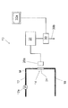
- FIG. 1 shows the configuration of a photoresist stripping apparatus 50 incorporating the photoresist component concentration measuring apparatus according to the present embodiment.
- the photoresist stripping device 50 includes a photoresist stripping solution tank 52, a conveyor 54 that conveys the workpiece 60, a shower 56 that sprays the photoresist stripping solution M on the workpiece 60, and the photoresist component concentration measuring device 10.
- the photoresist stripping apparatus 50 operates as follows. The workpiece 60 is placed on the conveyor 54 and transferred. Then, the photoresist stripping solution M is sprayed on the photoresist stripping solution tank 52, and the photoresist is stripped. The photoresist stripping solution M is recycled.
- the specified specific component may be an element, a chemical substance, or a chemical component as long as it is not contained in the photoresist stripping solution and is not decomposed or changed in the photoresist stripping solution.
- the photoresist stripping stock solution refers to an unused photoresist stripping solution after preparation.
- the photoresist when the photoresist contains NQD (naphthoquinone diazide sulfonate ester) as a photosensitizer and a novolak resin as a polymer resin, the photoresist contains sulfur, that is, a sulfur element.
- NQD naphthoquinone diazide sulfonate ester
- the photoresist stripping stock solution has a composition of MEA (monoethanolamine), BDG (diethylene glycol monobutyl ether) and water
- the photoresist stripping stock solution does not contain sulfur, that is, elemental sulfur.
- the sulfur element itself will change even if the sulfur-containing component changes due to decomposition in the photoresist stripping solution. There is nothing to do.
- the concentration of the photoresist dissolved in the photoresist stripping solution that is the photoresist concentration in the photoresist stripping solution, that is, The dissolved photoresist concentration can be calculated, and the photoresist concentration dissolved in the photoresist stripping solution can be measured accurately and accurately.
- the photoresist stripping solution M to be circulated is stored in the photoresist stripping solution tank 52 and sent to the shower 56 via the shower pipe 56b by the pump 56a.
- the shower pipe 56b is preferably provided with a filter 56c. This is because clogging can be prevented by the solid content of the photoresist.
- the process returns to the photoresist stripping solution tank 52.
- the photoresist stripping solution M is used cyclically.
- the photoresist in the photoresist stripper M is dissolved in the photoresist stripper M after being stripped.
- the concentration of the dissolved photoresist in the photoresist stripping solution tank 52 increases with time. Accordingly, the photoresist stripping solution M in the photoresist stripping solution tank 52 is partially or entirely replaced with a new solution which is a photoresist stripping solution stock solution when the dissolved dissolved photoresist reaches a certain concentration.
- the photoresist component concentration measuring apparatus 10 takes out the photoresist stripping solution M from the photoresist stripping solution tank 52, measures the amount of sulfur as a specific element in the dissolved photoresist, and strips the photoresist again. It returns to the liquid tank 52.
- reference numeral 12 i denotes an inlet for the photoresist stripping solution M
- reference numeral 18 o denotes an outlet for returning the photoresist stripping solution M obtained by measuring the amount of sulfur in the dissolved photoresist to the photoresist stripping solution tank 52.
- the photoresist stripping solution M whose amount of sulfur is measured may be discharged out of the system without returning to the photoresist stripping solution tank 52.
- FIG. 2 shows the configuration of the photoresist component concentration measuring apparatus 10.
- the photoresist component concentration measuring apparatus 10 includes a drawing pipe 12 communicating with the photoresist stripping solution tank 52, the drawing pipe 12, and a measuring unit 14 for measuring the photoresist stripping liquid M passing through the drawing pipe 12.
- a return pipe 18 is provided for returning the photoresist stripper M to the photoresist stripper tank 52.
- the fluorescent X-ray measuring device 20 as a measuring means for measuring the amount of sulfur as the specified specific element in the photoresist stripping solution M in the measuring unit 14, and the sulfur of the fluorescent X-ray measuring device 20
- a controller 30 is provided as calculation means for calculating the photoresist component concentration in the photoresist stripping solution M from the quantity measurement value.
- the extraction pipe 12 takes out a part of the photoresist stripping solution M from the photoresist stripping solution tank 52. Further, the drawing pipe 12 is provided with a pump 12a for transferring the photoresist stripping solution M. The pump 12a adjusts the pressure in the extraction pipe 12 at such a pressure that the photoresist stripping solution M can be handled without any trouble by the measurement unit 14 provided on the downstream side.
- the measuring unit 14 as a measuring means is provided continuously in the extraction pipe 12 so that the fluorescent X-ray measuring apparatus 20 measures the amount of sulfur in the photoresist stripping solution M, that is, the amount of sulfur. In FIG. 2, it is a portion that is continuously provided on the extraction pipe 12. In order to irradiate the photoresist stripping solution M with X-rays from the fluorescent X-ray measurement apparatus 20, the measurement unit 14 uses a material that transmits X-rays.
- the form of the measuring unit 14 as a measuring means is not particularly limited.
- a resin pipe that transmits X-rays as viewed from fluorescent X-rays communicates with the extraction pipe 12 as the measurement unit 14, or a measurement container that temporarily stores the photoresist stripping solution M from the extraction pipe 12 continues to the extraction pipe 12. It is possible to consider a form in which it is provided.
- the measurement unit 14 is configured by a pipe (hereinafter referred to as “transmission pipe”) 24 that transmits X-rays communicated with the extraction pipe 12.
- transmission pipe a pipe that transmits X-rays communicated with the extraction pipe 12.
- the transmission pipe 24 is made of a material that is hardly deteriorated by the photoresist stripping solution and transmits X-ray fluorescence. Examples include fluororesin, polyester, polypropylene, and the like, which are made of a material that transmits fluorescent X-rays when sulfur is measured by fluorescent X-rays.
- not all the transmission pipes 24 may be formed of a material that transmits X-rays. That is, only the portion where X-rays are emitted and fluorescent X-rays are generated may be the transmission pipe 24, and the other portion may be a metal pipe such as stainless steel. Moreover, it is good also as piping material which X-ray permeate
- FIG. 1 A block diagram illustrating an exemplary computing system.
- the photoresist stripping solution M obtained from the extraction pipe 12 may be received once in a measurement container, and the amount of sulfur may be measured with the photoresist stripping solution in the measurement container.
- the return pipe 18 communicates with the permeation pipe 24. Therefore, the photoresist stripping solution M sucked up from the photoresist stripping solution tank 52 by the pump 12 a passes through the extraction pipe 12, passes through the permeation pipe 24, and passes through the return pipe 18 to enter the photoresist stripping liquid tank 52. Return to.
- the fluorescent X-ray measuring apparatus 20 as a measuring means measures sulfur (S) as a specified specific element in the photoresist stripping solution M.
- the positive photoresist is composed of a photosensitive agent NQD (naphthoquinone diazide sulfonate ester) and a novolac resin.
- the exposed NQD becomes indenecarboxylic acid in the presence of alcohol and dissolves in an alkaline solution. Then, the bonds between the novolak resins are broken, and the exposed photoresist is peeled off and dissolved with an alkaline solution.
- the photoresist stripping solution M is composed of a new solution which is a stock solution of the photoresist stripping solution M, a dissolved novolak resin, and a dissolved NQD including a dissolved and changed structure.
- the dissolved novolak resin and the dissolved NQD including those that have been dissolved and changed structure are called photoresist components.
- the photoresist component is a dissolved dissolved photoresist.
- photoresist components that is, dissolved photoresists, are not all in a single form, but also include large lumps or those dissolved and decomposed to the basic structure of novolak resin.
- the amount of sulfur present in NQD does not change. Therefore, by measuring the amount of sulfur in the photoresist stripping solution M, the concentration of the photoresist component in the photoresist stripping solution M, that is, the dissolved dissolved photoresist concentration can be stably measured.
- the amount of sulfur that is, the amount of sulfur may be a value obtained by measuring the intensity of fluorescent X-rays of sulfur. That is, the sulfur amount may be the characteristic X-ray intensity (kcps) of sulfur.
- the photoresist component concentration measuring apparatus of the present invention uses sulfur in the photoresist component as an index of the concentration of the photoresist component, that is, the dissolved dissolved photoresist concentration. Therefore, if the component in the photoresist stripping solution contains a sulfate group, the concentration of the photoresist component cannot be accurately measured.
- the photoresist component concentration measuring apparatus 10 can be used when the photoresist stripping solution is composed only of a material that does not contain a sulfur element.
- the element contained in the photoresist and not contained in the photoresist stripping solution is specified, and the concentration of the specified specific element in the photoresist stripping solution is measured.
- FIG. 2 shows the detection unit 20a of the fluorescent X-ray measurement apparatus 20 in which an X-ray irradiation unit and a light receiving unit are combined.
- the irradiation unit and the light receiving unit may have different configurations.
- a controller 30 may be provided.
- the controller 30 calculates the photoresist component concentration in the photoresist stripping solution M from the flow rate of the photoresist stripping solution M in the permeation pipe 24 and the amount of sulfur measured by the fluorescent X-ray measuring device 20, and displays it on the display 30a. To display.
- the photoresist component concentration may be calculated as follows. First, a calibration solution having a determined photoresist component concentration is caused to flow through the permeation pipe 24 at a predetermined flow rate. Then, it is measured by the fluorescent X-ray measurement device 20.
- This measurement provides a calibration curve for the photoresist component concentration with respect to the measured sulfur content. Based on this calibration curve, the concentration of the photoresist component in the photoresist stripping solution M may be calculated.
- the controller 30 may have a transmission line 30b for transmitting a signal to another device when the photoresist component concentration reaches a certain value. This is to replace all or part of the photoresist stripping solution M in the photoresist stripping solution tank 52 when the photoresist component concentration of the photoresist stripping solution M reaches a certain value.
- the operation of the photoresist component concentration measuring apparatus 10 having the above configuration will be described.
- the photoresist stripping solution M is transferred to the photoresist component concentration measuring apparatus 10 through the drawing pipe 12 (see FIG. 1).
- the internal pressure in the extraction pipe 12 is adjusted by the pump 12a, and the photoresist stripping solution M is sent to the permeation pipe 24.
- the photoresist remover M that has passed through the permeation pipe 24 is returned to the photoresist remover tank 52 through the return pipe 18.
- the fluorescent X-ray measurement apparatus 20 measures the amount of sulfur in the photoresist stripping solution M flowing in the transmission pipe 24 according to an instruction from the controller 30. Then, the measured value is notified to the controller 30.
- Controller 30 calculates the sulfur concentration in photoresist stripping solution M using a calibration curve prepared in advance. Therefore, the controller 30 that performs such an operation may be referred to as calculation means. The calculated sulfur concentration is displayed on the display 30a. Moreover, it transmits as a signal to another apparatus (30b).
- the photoresist component concentration measuring apparatus 10 does not contain the photoresist stripping solution stock solution but contains the dissolved photoresist.
- the photoresist stripping solution M is based on sulfur atoms in the photoresist. Since the concentration of the photoresist component therein is measured, accurate concentration measurement can be performed even if the dissolved resist component in the photoresist stripping solution M is decomposed, changes over time, or changes in color.
- the photoresist stripping solution was composed of 19% MEA (monoethanolamine), 60% BDG (diethylene glycol monobutyl ether), and 21% water. None of the materials contains elemental sulfur.
- a positive photoresist using a novolak resin was exposed to light and then dried and powdered. Sulfur was used as a specific element.
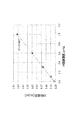
- the horizontal axis represents the concentration of the photoresist component which is the concentration of the dissolved photoresist (shown as “PR addition concentration [wt%]”), and the vertical axis represents the fluorescent X-ray intensity (“X-ray intensity”). (Kcps) ”).
- the X-ray intensity derived from the photoresist addition concentration and sulfur (S) with respect to the stripping solution has a wide range from a low concentration of 0.1 wt% or less to a high concentration of 1.0 wt%. There was a positive high correlation. Further, when the same sample was left for one week and remeasured, no change was observed.
- This graph is a result of measuring the concentration of the photoresist component, that is, the amount of sulfur in the photoresist stripping solution whose concentration of dissolved dissolved photoresist is known in advance by fluorescent X-ray. This can be used as a calibration curve as a calculation means.
- the concentration of the photoresist component that is, the amount of sulfur in the photoresist stripping solution whose concentration of dissolved dissolved photoresist is not known is measured by fluorescence X
- the concentration of the photoresist component can be obtained in reverse from the X-ray intensity.
- the calibration curve may not be a graph as shown in FIG. 3, but may be a table made up of numerical data.
- the photoresist component concentration measuring apparatus can be suitably used for a photoresist stripping process when performing fine processing using photolithography.
Landscapes
- General Physics & Mathematics (AREA)
- Physics & Mathematics (AREA)
- Immunology (AREA)
- Chemical & Material Sciences (AREA)
- Analytical Chemistry (AREA)
- Biochemistry (AREA)
- General Health & Medical Sciences (AREA)
- Life Sciences & Earth Sciences (AREA)
- Health & Medical Sciences (AREA)
- Pathology (AREA)
- Engineering & Computer Science (AREA)
- Condensed Matter Physics & Semiconductors (AREA)
- Manufacturing & Machinery (AREA)
- Computer Hardware Design (AREA)
- Microelectronics & Electronic Packaging (AREA)
- Power Engineering (AREA)
- Photosensitive Polymer And Photoresist Processing (AREA)
- Exposure Of Semiconductors, Excluding Electron Or Ion Beam Exposure (AREA)
- Analysing Materials By The Use Of Radiation (AREA)
Priority Applications (1)
| Application Number | Priority Date | Filing Date | Title |
|---|---|---|---|
| CN201680079908.3A CN108604534B (zh) | 2016-01-26 | 2016-12-26 | 光致抗蚀剂成分浓度测定装置及浓度测定方法 |
Applications Claiming Priority (2)
| Application Number | Priority Date | Filing Date | Title |
|---|---|---|---|
| JP2016012558A JP6643710B2 (ja) | 2016-01-26 | 2016-01-26 | フォトレジスト成分濃度測定装置および濃度測定方法 |
| JP2016-012558 | 2016-01-26 |
Publications (1)
| Publication Number | Publication Date |
|---|---|
| WO2017130620A1 true WO2017130620A1 (ja) | 2017-08-03 |
Family
ID=59398246
Family Applications (1)
| Application Number | Title | Priority Date | Filing Date |
|---|---|---|---|
| PCT/JP2016/088687 Ceased WO2017130620A1 (ja) | 2016-01-26 | 2016-12-26 | フォトレジスト成分濃度測定装置および濃度測定方法 |
Country Status (4)
| Country | Link |
|---|---|
| JP (1) | JP6643710B2 (enExample) |
| CN (1) | CN108604534B (enExample) |
| TW (1) | TWI697743B (enExample) |
| WO (1) | WO2017130620A1 (enExample) |
Families Citing this family (2)
| Publication number | Priority date | Publication date | Assignee | Title |
|---|---|---|---|---|
| DE102020130415B4 (de) | 2019-12-26 | 2025-01-09 | Taiwan Semiconductor Manufacturing Co., Ltd. | Versorgungssystem für chemische flüssigkeiten und verfahren zur versorgung mit chemischen flüssigkeiten |
| US11715656B2 (en) | 2019-12-26 | 2023-08-01 | Taiwan Semiconductor Manufacturing Co., Ltd. | Chemical liquid supplying system and method of supplying chemical liquid |
Citations (5)
| Publication number | Priority date | Publication date | Assignee | Title |
|---|---|---|---|---|
| JP2000058411A (ja) * | 1998-08-04 | 2000-02-25 | Mitsubishi Electric Corp | 半導体製造装置 |
| JP2005191030A (ja) * | 2003-12-24 | 2005-07-14 | Sharp Corp | レジスト除去装置およびレジスト除去方法 |
| JP2005535780A (ja) * | 2002-08-09 | 2005-11-24 | イー・アイ・デュポン・ドウ・ヌムール・アンド・カンパニー | フォトレジスト、フルオロポリマーおよび157nm微細平版印刷のための方法 |
| JP2014096462A (ja) * | 2012-11-08 | 2014-05-22 | Panasonic Corp | フォトレジスト濃度測定装置および測定方法 |
| JP2015162659A (ja) * | 2014-02-28 | 2015-09-07 | 芝浦メカトロニクス株式会社 | 処理装置および処理方法 |
Family Cites Families (4)
| Publication number | Priority date | Publication date | Assignee | Title |
|---|---|---|---|---|
| JP3093975B2 (ja) * | 1996-07-02 | 2000-10-03 | 株式会社平間理化研究所 | レジスト剥離液管理装置 |
| JP2007316360A (ja) * | 2006-05-26 | 2007-12-06 | Nishimura Yasuji | 水系フォトレジスト剥離液の管理方法および管理装置 |
| JP4923882B2 (ja) * | 2006-09-07 | 2012-04-25 | 三菱化学エンジニアリング株式会社 | フォトレジスト供給装置およびフォトレジスト供給方法 |
| JP5019393B2 (ja) * | 2008-04-14 | 2012-09-05 | 東亞合成株式会社 | 導電性高分子膜上のレジスト被膜の除去方法および除去装置 |
-
2016
- 2016-01-26 JP JP2016012558A patent/JP6643710B2/ja active Active
- 2016-12-26 CN CN201680079908.3A patent/CN108604534B/zh active Active
- 2016-12-26 WO PCT/JP2016/088687 patent/WO2017130620A1/ja not_active Ceased
- 2016-12-30 TW TW105144149A patent/TWI697743B/zh active
Patent Citations (5)
| Publication number | Priority date | Publication date | Assignee | Title |
|---|---|---|---|---|
| JP2000058411A (ja) * | 1998-08-04 | 2000-02-25 | Mitsubishi Electric Corp | 半導体製造装置 |
| JP2005535780A (ja) * | 2002-08-09 | 2005-11-24 | イー・アイ・デュポン・ドウ・ヌムール・アンド・カンパニー | フォトレジスト、フルオロポリマーおよび157nm微細平版印刷のための方法 |
| JP2005191030A (ja) * | 2003-12-24 | 2005-07-14 | Sharp Corp | レジスト除去装置およびレジスト除去方法 |
| JP2014096462A (ja) * | 2012-11-08 | 2014-05-22 | Panasonic Corp | フォトレジスト濃度測定装置および測定方法 |
| JP2015162659A (ja) * | 2014-02-28 | 2015-09-07 | 芝浦メカトロニクス株式会社 | 処理装置および処理方法 |
Also Published As
| Publication number | Publication date |
|---|---|
| TWI697743B (zh) | 2020-07-01 |
| CN108604534A (zh) | 2018-09-28 |
| JP2017135204A (ja) | 2017-08-03 |
| JP6643710B2 (ja) | 2020-02-12 |
| TW201736987A (zh) | 2017-10-16 |
| CN108604534B (zh) | 2022-06-21 |
Similar Documents
| Publication | Publication Date | Title |
|---|---|---|
| JP3093975B2 (ja) | レジスト剥離液管理装置 | |
| US20140083458A1 (en) | Photoresist stripping solution, stripping solution recycling system and operating method, and method for recycling stripping solution | |
| KR102442878B1 (ko) | 리소그래피용 도포막 형성용 조성물의 제조 방법 및 패턴 형성 방법 | |
| KR102455657B1 (ko) | 수지 마스크 박리용 세정제 조성물 | |
| TW583516B (en) | Alkaline system working fluid, method and apparatus for preparing working fluid and method and apparatus for feeding working fluid | |
| TWI278898B (en) | Processing solution preparation and supply method and apparatus | |
| WO2017130620A1 (ja) | フォトレジスト成分濃度測定装置および濃度測定方法 | |
| TWI312105B (enExample) | ||
| KR20210063248A (ko) | 차아염소산 제 4 급 알킬암모늄 용액, 그 제조 방법 및 반도체 웨이퍼의 처리 방법 | |
| JP3126690B2 (ja) | レジスト剥離液管理装置 | |
| JPH10207082A (ja) | フォトレジスト用アルカリ現像液又はその現像廃液又はその処理液の分析管理方法及び装置 | |
| JP2602179B2 (ja) | レジスト剥離液管理装置 | |
| KR20030001335A (ko) | 비수계 내식막 박리액 관리장치 및 비수계 내식막 박리액관리방법 | |
| JP2003131398A (ja) | アルカリ系加工液、加工液調整方法及び装置、並びに、加工液供給方法及び装置 | |
| JP2003122029A (ja) | レジスト剥離液の管理方法 | |
| TW201800751A (zh) | 氧化劑濃度之測定方法及測定裝置、以及電子材料洗淨裝置 | |
| JP2010243200A (ja) | 過酸化水素含有水溶液中の過酸化水素濃度の測定方法 | |
| JP6551784B2 (ja) | レジスト剥離液中の炭酸濃度管理方法および炭酸濃度管理装置 | |
| JP2005191030A (ja) | レジスト除去装置およびレジスト除去方法 | |
| JP2009191312A (ja) | エッチング制御装置 | |
| Asaumi et al. | Mechanism of Photoresist Resolution Improvement by Pre‐exposure Treatment | |
| JP2007316360A (ja) | 水系フォトレジスト剥離液の管理方法および管理装置 | |
| KR20080020140A (ko) | 식각액 관리 시스템, 식각 장치 및 이에 의한 식각액 관리방법 | |
| JP6551787B2 (ja) | レジスト剥離液中の炭酸濃度管理方法および炭酸濃度管理装置 | |
| WO2024142428A1 (ja) | 配線回路基板の製造方法 |
Legal Events
| Date | Code | Title | Description |
|---|---|---|---|
| 121 | Ep: the epo has been informed by wipo that ep was designated in this application |
Ref document number: 16888204 Country of ref document: EP Kind code of ref document: A1 |
|
| NENP | Non-entry into the national phase |
Ref country code: DE |
|
| 122 | Ep: pct application non-entry in european phase |
Ref document number: 16888204 Country of ref document: EP Kind code of ref document: A1 |