WO2017130284A1 - 音響特性測定装置及び音響特性測定方法 - Google Patents
音響特性測定装置及び音響特性測定方法 Download PDFInfo
- Publication number
- WO2017130284A1 WO2017130284A1 PCT/JP2016/052100 JP2016052100W WO2017130284A1 WO 2017130284 A1 WO2017130284 A1 WO 2017130284A1 JP 2016052100 W JP2016052100 W JP 2016052100W WO 2017130284 A1 WO2017130284 A1 WO 2017130284A1
- Authority
- WO
- WIPO (PCT)
- Prior art keywords
- measured
- sound output
- acoustic characteristic
- sound
- recording
- Prior art date
- Legal status (The legal status is an assumption and is not a legal conclusion. Google has not performed a legal analysis and makes no representation as to the accuracy of the status listed.)
- Ceased
Links
Images




Classifications
-
- G—PHYSICS
- G01—MEASURING; TESTING
- G01H—MEASUREMENT OF MECHANICAL VIBRATIONS OR ULTRASONIC, SONIC OR INFRASONIC WAVES
- G01H3/00—Measuring characteristics of vibrations by using a detector in a fluid
-
- G—PHYSICS
- G01—MEASURING; TESTING
- G01H—MEASUREMENT OF MECHANICAL VIBRATIONS OR ULTRASONIC, SONIC OR INFRASONIC WAVES
- G01H17/00—Measuring mechanical vibrations or ultrasonic, sonic or infrasonic waves, not provided for in the other groups of this subclass
-
- G—PHYSICS
- G01—MEASURING; TESTING
- G01H—MEASUREMENT OF MECHANICAL VIBRATIONS OR ULTRASONIC, SONIC OR INFRASONIC WAVES
- G01H7/00—Measuring reverberation time ; room acoustic measurements
-
- G—PHYSICS
- G10—MUSICAL INSTRUMENTS; ACOUSTICS
- G10K—SOUND-PRODUCING DEVICES; METHODS OR DEVICES FOR PROTECTING AGAINST, OR FOR DAMPING, NOISE OR OTHER ACOUSTIC WAVES IN GENERAL; ACOUSTICS NOT OTHERWISE PROVIDED FOR
- G10K15/00—Acoustics not otherwise provided for
-
- H—ELECTRICITY
- H04—ELECTRIC COMMUNICATION TECHNIQUE
- H04R—LOUDSPEAKERS, MICROPHONES, GRAMOPHONE PICK-UPS OR LIKE ACOUSTIC ELECTROMECHANICAL TRANSDUCERS; ELECTRIC HEARING AIDS; PUBLIC ADDRESS SYSTEMS
- H04R3/00—Circuits for transducers
-
- H—ELECTRICITY
- H04—ELECTRIC COMMUNICATION TECHNIQUE
- H04S—STEREOPHONIC SYSTEMS
- H04S5/00—Pseudo-stereo systems, e.g. in which additional channel signals are derived from monophonic signals by means of phase shifting, time delay or reverberation
- H04S5/02—Pseudo-stereo systems, e.g. in which additional channel signals are derived from monophonic signals by means of phase shifting, time delay or reverberation of the pseudo four-channel type, e.g. in which rear channel signals are derived from two-channel stereo signals
Definitions
- the present invention relates to an acoustic characteristic measuring device, an acoustic characteristic measuring method, an acoustic characteristic measuring program, and a recording medium on which the acoustic characteristic measuring program is recorded.
- Patent Document 1 discloses a technique for performing the following (i) and (ii).
- a space for example, a concert hall
- the acoustic characteristics in the passenger compartment are measured.
- the acoustic effect of the target space is reproduced in the passenger compartment.
- Such acoustic characteristic measurement utilizes the fact that the sound collection signal Y (t) from the microphone is the result of convolution integration of the output sound signal X (t) from the speaker and the impulse response h (t) of the measured system. ing. That is, in the conventional technique, the impulse response h (t) is calculated based on the sound collection signal Y (t) when an impulse signal or the like is used as the output sound signal X (t). Subsequently, the transfer function H ( ⁇ ) obtained by Fourier transforming the impulse response h (t) is obtained as the acoustic characteristics of the system under measurement.
- the above-described prior art technique is premised on that the time adjustment between the sound output system for outputting sound and the recording system for recording is performed with high accuracy when measuring the acoustic characteristics. If the time adjustment accuracy is low, phase characteristics that are unpredictable within the accuracy range between the transfer function measured as the acoustic characteristics and the true transfer function for each measurement target system. The difference will occur.
- a standard portable device having a recording function for performing recording of one system, a wireless communication function and a control function thereof, and an arithmetic processing function, for example, a smartphone or the like is widely used.
- Use of such a standard portable device is convenient because the sound collection position can be easily changed.
- the said standard portable apparatus while giving the sound output start command to the sound output type
- the interaural phase difference at a frequency of about 250 Hz to 1 kHz or less is related to sound image localization in the left-right direction.
- the sound image localization can be controlled by controlling the interaural phase difference by setting the speaker position and the delay time applied to the original sound signal when the sound is applied to each speaker.
- a true transfer function for each of a plurality of measured systems determined by the position of at least one speaker and each of the right ear position and the left ear position of the human at the assumed listening position It is preferable to measure the binaural phase difference corresponding to each speaker.
- the sound output time from the speaker for each of the measured systems is used as the reference time, and the elapsed time from the reference time is combined with high accuracy. If the impulse response information for each of the plurality of systems to be measured can be specified, the difference in phase characteristics such as the interaural phase difference can be measured as the acoustic characteristics.
- the invention according to claim 1 is based on recorded data recorded corresponding to sound output sequentially performed according to a predetermined time schedule for each of a plurality of measured systems determined by a pair of sound output position and sound collection position.
- An extraction unit that extracts recording data of an extraction section in which an impulse response reflection waveform falls within the extraction section in a system under measurement whose sound output order is immediately before and a difference in sound output time between the system under test and the immediately preceding system;
- An acoustic characteristic measuring device comprising: a calculating unit that calculates acoustic characteristic information for each of the plurality of measured systems based on recording data for each section.
- the invention according to claim 5 is an acoustic characteristic measuring method used in an acoustic characteristic measuring apparatus including an extracting unit; and a calculating unit, wherein the extracting unit is based on a pair of a sound output position and a sound collecting position. From the recording data recorded corresponding to the sound output sequentially performed according to a predetermined time schedule for each of a plurality of measured systems to be measured, the recording data of the extracted section where the impulse response reflected waveform is contained is recorded in the sound output order immediately before the sound output order. An extraction step of extracting based on a difference in sound output time between the extraction section in the measurement system and the immediately preceding system to be measured; and the calculation unit based on the recording data for each of the extraction sections. And a calculation step of calculating acoustic characteristic information for each.
- the invention described in claim 6 is an acoustic characteristic measurement program that causes a computer included in the acoustic characteristic measurement apparatus to execute the acoustic characteristic measurement method according to claim 5.
- the invention according to claim 7 is a recording medium in which the acoustic characteristic measurement program according to claim 6 is recorded so as to be readable by a computer included in the acoustic characteristic measurement device.
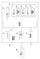
- 1 is a block diagram illustrating a schematic configuration of an acoustic characteristic measurement device according to an embodiment of the present invention.
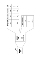
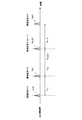
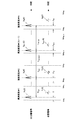
- 1 is a block diagram illustrating a schematic configuration of an acoustic characteristic measuring apparatus according to an embodiment of the present invention. It is a figure for demonstrating the content of the measurement condition information of FIG. It is a figure for demonstrating the sound output timing according to the time schedule of FIG. It is a figure for demonstrating the content of the sound recording data of FIG. 2, extraction data, and acoustic characteristic information. It is a figure for demonstrating the recording area in each to-be-measured system. It is a flowchart for demonstrating an extraction process and an acoustic characteristic calculation process.
- DESCRIPTION OF SYMBOLS 100 ... Acoustic characteristic measuring apparatus 110 ... Processing control unit (a part of recording part, an extraction part, a calculation part) 150 ... Sound collection unit (part of recording section) 700 ... Acoustic characteristic measuring device 710 ... Recording unit 730 ... Extraction unit 740 ... Calculation unit
- FIG. 1 shows a schematic configuration of an acoustic characteristic measuring apparatus 700 according to an embodiment.
- the acoustic characteristic measuring apparatus 700 collects sound output from the speaker of the sound output unit 800 disposed outside the acoustic characteristic measuring apparatus 700.
- the arrangement position of each speaker is a fixed position.
- the number of speakers may be one or two or more.
- the acoustic characteristic measuring device 700 includes a recording unit 710 and a storage unit 720. In addition, the acoustic characteristic measurement device 700 includes an extraction unit 730 and a calculation unit 740.
- the recording unit 710 includes one microphone MC and a timing mechanism.
- the recording unit 710 starts the recording process when recording start is designated by an input unit (not shown).
- the recording unit 710 samples the amplitude of the sound collected by the microphone MC at a predetermined sample frequency and converts it into a digital value until recording interruption is designated by the input unit. The result of this conversion is sent to the storage unit 720 as recorded waveform data.
- the system to be measured is determined by the pair of the sound output position (arrangement position of the speaker that outputs sound) and the sound collection position (arrangement position of the microphone MC). And according to the predetermined time schedule mentioned later, the sound output for every to-be-measured system is performed sequentially.
- each of the measured systems is referred to as measured system # 1, measured system # 2,..., Measured system #N in the order of sound output according to the time schedule.
- various information is recorded. Such information includes measurement condition information, recording data, extracted data, and acoustic characteristic information.
- Measured condition information includes measured system information and time schedule.
- the time difference T k, k + 1 is determined in advance based on the time required for setting the change of the measurement target system from the measured system # (k ⁇ 1) to the measured system #k.
- the recording data includes the recording start time and recording waveform data for each system under test #j.
- the extracted data includes extracted waveform data for each system #j to be measured.
- the acoustic characteristic information includes acoustic characteristic information for each system to be measured #j.
- the extraction unit 730 calculates an extraction interval related to the measured system #j. Subsequently, the extraction unit 730 extracts the recorded waveform data of the calculated extraction section as extracted waveform data #j. Then, the extraction unit 730 stores the extracted waveform data #j extracted in the storage unit 720.
- the calculation unit 740 calculates acoustic characteristic information based on the extracted waveform data #j. Then, the calculation unit 740 stores the calculated acoustic characteristic information in the storage unit 720.
- the acoustic characteristic information calculation process by the calculation unit 740 will be described later.
- the acoustic characteristic measuring apparatus 700 first performs recording processing when measuring acoustic characteristics. In such recording processing, recording processing is performed for each measured system in the order of measured system # 1, measured system # 2,..., Measured system #N.
- the microphone MC is arranged at a sound collection position corresponding to the system to be measured # 1. Subsequently, when the recording start using the input unit is designated to the recording unit 710, the recording unit 710 starts the recording process.
- the sound output unit 800 is designated to start sound output.
- the sound output unit 800 first outputs a sound corresponding to the output sound signal X 1 (t) from the sound output position corresponding to the measured system # 1, and then follows the time schedule according to the time schedule. Sound output corresponding to the output sound signal X k (t) is performed from the sound output position corresponding to #k.
- the recording unit 710 When the recording unit 710 receives a recording start instruction during the recording process for the system under test # 1, first, the recording unit 710 detects the recording start time trs 1 for the system under test # 1 using the time measuring mechanism within the recording unit 710. To do. Then, the recording unit 710 stores the detected recording start time trs 1 in the storage unit 720 as the head data of the recording data area for the system to be measured # 1.
- the recording unit 710 samples the amplitude of the sound collected by the microphone MC at a predetermined sample frequency and converts it into a digital value. Then, the recording unit 710 stores the conversion result as the recording waveform data # 1 in the recording data area for the measured system # 1 in the storage unit 720.
- the microphone MC is arranged. Only the position is changed.
- the recording unit 710 executes the recording process in the same manner as in the case of the measured system # 1, and the recording start time and the recorded waveform data # of the measured system #k are recorded. k is stored in the recording data area for the system to be measured #k in the storage unit 720. Thereafter, while changing the setting of the system under measurement, the recording process is executed in the same manner as in the case of the system under test # 1 until the recording process for the system under test #N is completed.
- the recording process by the recording unit 710 is performed in a quiet sound environment except for the sound output corresponding to the output sound signal X j (t).
- the extraction unit 730 first reads the data in the recording data area for the measured system # 1 in the storage unit 720. Subsequently, based on the read recording start time trs 1 and recording waveform data # 1, and the shortest distance D MIN and longest distance D MAX among the distances D 1 to D N in the storage unit 720, the extraction unit 730 The extraction interval [tes 1 , tee 1 ] is determined.
- time tes 1 is the start time of the extraction section.
- Time tee 1 is the end time of the extraction section.
- the extraction unit 730 detects a threshold arrival time that first reaches a threshold determined according to the maximum value in the recorded waveform data # 1. Subsequently, the extraction unit 730 calculates the time tes 1 based on the time when the amplitude first has an effective amplitude before the threshold arrival time and the difference between the distance D 1 and the shortest distance D MIN . Further, the extraction unit 730 calculates the time tee 1 based on the time when the first effective amplitude is not reached after the threshold arrival time and the difference between the distance D 1 and the maximum distance D MAX .
- the extraction unit 730 extracts data of the extraction section [tes 1 , tee 1 ] from the recording waveform data # 1. Then, the extracting unit 730 stores the extracted data as extracted waveform data # 1 in the extracted data area for the measured system # 1 in the storage unit 720.
- the extraction unit 730 sequentially calculates the extraction interval [tes k , te k ] for each of the measured systems # 2 to #N and extracts the extraction interval [tes k , the extraction of the data of the tee k]. Then, the extracting unit 730 stores the extracted waveform data related to the measured system #k in the extracted data area for the measured system #k in the storage unit 720.
- the extraction unit 730 calculates times tes k and te k by the following equations (1) and (2).
- tes k tes k-1 + T k-1, k ...
- tee k tee k-1 + T k-1, k ...
- the calculation unit 740 starts the calculation process of the acoustic characteristic information of the system under test #j.
- the impulse response reflection information h j (t) calculated in this way is obtained by shifting the impulse response of the system under test #j along the time direction by a movement time common to all of the systems under test # 1 to #N. ing.
- the calculation unit 740 performs Fourier transform on the impulse response reflection information h j (t), and calculates transfer function information H j ( ⁇ ) as acoustic characteristic information of the system to be measured #j. Then, the calculation unit 740 stores the calculated transfer function information H j ( ⁇ ) in the acoustic characteristic information area for the measured system #j in the storage unit 720.
- the transfer function information H j ( ⁇ ) calculated as described above is different only in phase characteristics compared to the true transfer function of the system to be measured #j.
- the difference in phase characteristics between the transfer function information H j ( ⁇ ) and the true transfer function is common to all the systems to be measured # 1 to #N.
- the transfer function information H j ( ⁇ ) reflects the true attenuation characteristic in the measured system #j
- the difference in the phase characteristics reflects the difference in the phase characteristics between the true transfer functions of the systems to be measured #q and #r.
- the transfer function information H j ( ⁇ ) calculated in this way is transmitted to an acoustic characteristic control device (not shown) via a communication unit (not shown). Then, the acoustic characteristic control device controls the acoustic characteristics for high-accuracy sound image localization by using the transfer function information H j ( ⁇ ).
- the present embodiment it is possible to accurately detect the acoustic characteristic information of each of the plurality of measured systems in a mode in which a difference in phase characteristics between the acoustic characteristics of the plurality of measured systems can be accurately detected, and It can be measured with high accuracy.
- an impulse response reflection waveform obtained with respect to the sound output in the first measured system # 1 in the sound output order (ii) a sound output position and sound collection in the measured system # 1
- the distance D 1 between the positions (iii) the shortest distance D MIN among the distances between the sound output positions and the sound collection positions in the measured systems # 1 to #N, and (iv) the measured Based on the distance D MAX which is the longest of the distances between the sound output positions and the sound collection positions in the systems # 1 to #N, the recording waveform data extraction section for the system to be measured # 1 is determined. For this reason, it is possible to rationally determine the extraction interval for each of the systems to be measured # 1 to #N.
- the predetermined time schedule is created based on the time required for changing the setting of the measurement target system to the next system to be measured in the sound output order. For this reason, the recording process can be performed with a reasonable time schedule.
- the speaker of the sound output unit is disposed at a fixed position.
- the acoustic characteristic measuring device is provided with the recording unit.
- the resource can be used, and the acoustic characteristic measuring apparatus can be configured without the recording unit.
- a part or all of the extraction unit 730 and the calculation unit 740 of the acoustic characteristic measurement apparatus 700 of the above embodiment is configured as a computer as a calculation unit including a central processing unit (CPU: Central Processing Unit), and the like. You may make it fulfill
- This program is recorded on a computer-readable recording medium such as a hard disk, CD-ROM, or DVD, and is loaded from the recording medium and executed by the computer.
- the program may be acquired in a form recorded on a portable recording medium such as a CD-ROM or DVD, or may be acquired in a form distributed via a network such as the Internet. Also good.
- FIG. 2 shows a schematic configuration of an acoustic characteristic measuring apparatus 100 according to an embodiment.
- the acoustic characteristic measuring apparatus 100 is an aspect of the acoustic characteristic measuring apparatus 700 (see FIG. 1) of the first embodiment described above.
- the sound output from the speaker of the sound output unit 200 arranged outside the acoustic characteristic measuring apparatus 100 is recorded.
- the number of speakers in the sound output unit 200 may be one as in the case of the sound output unit 800 described above, or may be two or more.
- the arrangement position of each speaker in the sound output unit 200 is a fixed position as in the sound output unit 800. That is, the sound output unit 200 according to the present example fulfills the function of the sound output unit according to the above-described embodiment.
- the acoustic characteristic measuring device 100 includes a processing control unit 110, a storage unit 120, and an input unit 130.
- the acoustic characteristic measuring apparatus 100 includes a display unit 140, a sound collection unit 150, and a wireless communication unit 160.
- the above processing control unit 110 performs overall control of the entire acoustic characteristic measuring apparatus 100 and performs various processes.
- the processing control unit 110 will be described later.
- the storage unit 120 includes a nonvolatile storage element, and stores various information data used in the acoustic characteristic measuring apparatus 100.
- Such information data includes measurement condition information MCI, recording data RCD, extracted data ETD, and acoustic characteristic information SCI. That is, the storage unit 120 is configured to perform the function of the storage unit 720 in the above-described embodiment.
- the contents of the measurement condition information MCI, recording data RCD, extracted data ETD, and acoustic characteristic information SCI stored in the storage unit 120 will be described later.
- the input unit 130 includes a key unit provided in the main body of the acoustic characteristic measuring device 100 and / or a remote input device including the key unit.
- a key part provided in the main body part a touch panel provided in a display device of the display unit 140 can be used.
- it can replace with the structure which has a key part, or can also employ
- the processing content of the acoustic characteristic measuring apparatus 100 is designated.
- Such designation includes a recording start designation by the processing control unit 110 and a recording interruption designation. That is, the input unit 140 functions as the input unit in the above-described embodiment.
- the display unit 140 receives the image data sent from the processing control unit 110. Then, the display unit 140 displays an image corresponding to the image data.
- the images displayed on the display unit 140 in this way include an image that presents each measurement stage in the acoustic characteristic measurement in the acoustic characteristic measurement apparatus 100, an image that presents guidance for the next operation to be performed in each measurement stage, and the like. include.
- the sound collection unit 150 includes a single microphone MC.
- the recording process is started.
- the sound collection unit 150 samples the amplitude of the sound collected by the microphone MC at a predetermined sampling frequency and converts it into a digital value until recording interruption is designated by the input unit.
- the result of this conversion is sent to the processing control unit 110 as recorded waveform data. That is, the sound collection unit 150 performs a part of the function of the recording unit 710 in the above-described embodiment.
- the wireless communication unit 160 communicates with an external acoustic characteristic control device under the control of the processing control unit 110.
- the processing control unit 110 receives new measurement condition information from the acoustic characteristic control device, or transmits the measurement result of the acoustic characteristic to the acoustic characteristic control device.
- the processing control unit 110 includes a central processing unit (CPU) and peripheral circuits (including a timing mechanism). Various functions as the acoustic characteristic measuring apparatus 100 are realized by the processing control unit 110 executing various programs. These functions include the functions of the extraction unit 730 and the calculation unit 740 in the above-described embodiment.
- the processing control unit 110 uses the wireless communication unit 160 to receive measurement condition information for new acoustic characteristic measurement from the acoustic characteristic control device. Then, the process control unit 110 stores the newly received measurement condition information in the storage unit 120 as measurement condition information MCI.
- the processing control unit 110 performs an acoustic characteristic measurement process according to the measurement condition information MCI in the storage unit 120.
- Such measurement processing includes recording processing, extraction processing, and acoustic characteristic calculation processing.
- the measurement process includes an operation guidance image creation process in the recording process.
- the processing control unit 110 uses the wireless communication unit 160 to transmit the acoustic characteristic measurement result to the acoustic characteristic control device.
- the program executed by the processing control unit 110 is recorded on a computer-readable recording medium such as a hard disk, CD-ROM, or DVD, and is loaded from the recording medium and executed.
- the program may be acquired in a form recorded on a portable recording medium such as a CD-ROM or DVD, or may be acquired in a form distributed via a network such as the Internet. Also good.
- the measurement condition information MCI includes measured system information and a time schedule.
- the distance D j between PM j is included. Note that when the number of arranged in a fixed position the speaker is one, all of the sound output position PS j are the same.
- FIG. 4 shows the sound output timing when sound is output according to such a time schedule.
- the time difference T k ⁇ 1, k is determined in advance based on the time required to set the change of the measurement target system from the measured system # (k ⁇ 1) to the measured system #k.
- the recording data RCD includes recording waveform data #j for each system to be measured #j.
- the extracted data ETD includes extracted waveform data #j extracted from the recorded waveform data #j for each measured system #j.
- the acoustic characteristic information SCI includes transfer function information H j ( ⁇ ) ( ⁇ : angular frequency), which is acoustic characteristic information for each measured system #j.
- the acoustic characteristic measuring apparatus 100 first performs a recording process when measuring acoustic characteristics. In such recording processing, recording processing is performed for each measured system in the order of measured system # 1, measured system # 2,..., Measured system #N.
- the recording about the system under measurement # 1 first, a microphone MC is arranged in the sound collection position PM 1. Subsequently, upon receiving a recording start designation from the input unit 130, the processing control unit 110 starts a recording process relating to the system # 1 to be measured. In the recording process related to the system under test # 1, the processing control unit 110 first detects the recording start time trs 1 related to the system under test # 1 using a time measuring mechanism. Subsequently, the processing control unit 110 stores the detected recording start time trs 1 in the storage unit 120 as the head data of the recording data area for the system under test # 1. Then, the processing control unit 110 starts collecting the amplitude data sequentially transmitted from the sound collection unit 150, and sequentially stores the collected amplitude data in the recording data area for the measured system # 1 in the storage unit 120. Store.
- the sound output unit 200 is designated to start sound output.
- the sound output unit 200 first outputs a sound corresponding to the output sound signal X 1 (t) from the speaker corresponding to the measured system # 1. Thereafter, sound output corresponding to the output sound signal X k (t) from the speaker corresponding to the system to be measured #k is automatically performed at the timing shown in FIG. 4 according to the time schedule described above.
- a recording start designation is received from the input unit 130 after a sufficient time has elapsed for detection of the impulse response information h 1 (t).
- the microphone MC is arranged. Only the position is changed.
- the processing control unit 110 receives a recording start specified, as in the case of the measurement system # 1 described above, by executing the recording process, recording start time trs k and recording waveform of the measurement system #k
- the data #k is stored in the recording data area for the measured system #k in the storage unit 120.
- the recording process is executed in the same manner as in the case of the system under test # 1 described above until the recording process for the system under test #N is completed while changing the setting of the system under test.
- FIG. 6 shows an example of the recording start time trs j and the recording end time tre j for the system under test #j in comparison with the sound output timing from the sound output unit 200 shown in FIG. Yes.
- the sound related to the system #j to be measured The difference ( ⁇ j ) between the output time and the recording start time is generally different between the measured systems.
- the recording process by the processing control unit 110 is performed in a quiet sound environment except for the sound output corresponding to the output sound signal X j (t).
- step S11 the process control unit 110 sets the value of the parameter p to “1”. Subsequently, in step S12, the processing control unit 110 determines the extraction interval [tes 1 , te 1 ] for the system under measurement # 1, that is, the extraction start time tes 1 and the end time tee 1 for the system under measurement # 1. decide.
- step S12 Details of the determination process of the start time tes 1 and the end time tee 1 in step S12 will be described later.
- step S13 the processing control unit 110 extracts the data [Y 1 (tes j ),..., Y 1 (tee j )] from the recording waveform data # 1 in the extraction section [tes 1 , tee 1 ]. To extract. Then, the processing control unit 110 uses the extracted data [Y 1 (tes j ),..., Y 1 (tee j )] as the extracted waveform data # 1 for the measured system # 1 in the storage unit 120. Stored in the extracted data area.
- step S14 the process control unit 110 increments the value of the parameter p (adds “1”).
- step S15 the processing control unit 110 determines the extraction interval [tes p , te p ] for the measured system # 1, that is, the extraction start time tes p and the end time tee p for the measured system #p. , Calculated by the above-described equations (1) and (2).
- step S16 the processing control unit 110 selects the data [Y p (tes p ),..., Y p (te p )] of the extraction section [tes p , te p ] from the recorded waveform data #p. To extract. Then, the processing control unit 110 uses the extracted data [Y p (tes p ),..., Y p (te p )] as the extracted waveform data #p for the measured system #p in the storage unit 120. Stored in the extracted data area.
- step S17 the processing control unit 110 determines whether or not the value of the parameter p is “N”, so that the extraction processing for all the measured systems # 1 to #N is completed. Determine whether or not. If the result of the determination in step S17 is negative (step S17: N), the process returns to step S14. Then, the processes in steps S14 to S17 are repeated until the result of the determination in step S17 becomes affirmative.
- step S17 When the extraction process for all of the measured systems # 1 to #N is finished and the result of the determination in step S17 is affirmative (step S17: Y), the process proceeds to step S18.
- step S18 the processing control unit 110 calculates transfer function information H j ( ⁇ ) as acoustic characteristic information of the system to be measured #j.
- FIG. 8 an example of the extraction section start time tes j and end time tee j for the system under test #j is compared with the sound output timing from the sound output unit 200 shown in FIG. It is shown.
- high-precision time adjustment is not performed between the timing mechanism in the sound output unit 200 and the timing mechanism in the acoustic characteristic measuring apparatus 100, but the sound related to the system #j to be measured
- the difference ( ⁇ 0 ) between the output time and the start time of the extraction interval is common between the measured systems. That is, it can be said that relative time adjustment after the reference time is performed between the measured systems, with the sound output start time for each measured system as the reference time.
- the waveform corresponding to the extracted waveform data #j is denoted as “Y j (t)”.
- the process control unit 110 first extracts the extracted waveform data #j [Y j (tes j ),..., Y j (from the extracted data area for the measured system #j in the storage unit 120. te j )]. Subsequently, the processing control unit 110 assumes that the start time of the sound output from the sound output unit 200 in the measured system #j is “time tes j ” based on the read extracted waveform data #j, and the impulse response reflection information h j (t) is calculated.
- the impulse response reflection information h j (t) calculated in this way is the movement time (time ⁇ 0 ) common to all of the measured systems # 1 to #N along the time direction of the impulse response of the measured system #j. It is only shifted.
- the processing control unit 110 performs Fourier transform on the impulse response reflection information h j (t) to calculate transfer function information H j ( ⁇ ) as acoustic characteristic information of the system to be measured #j. Then, the process control unit 110 stores the calculated transfer function information H j ( ⁇ ) in the acoustic characteristic information area for the measured system #j in the storage unit 120.
- the transfer function information H j ( ⁇ ) calculated as described above is different only in phase characteristics compared to the true transfer function of the system to be measured #j.
- the difference in phase characteristics between the transfer function information H j ( ⁇ ) and the true transfer function is common to all the systems to be measured # 1 to #N.
- the transfer function information H j ( ⁇ ) reflects the true attenuation characteristic in the measured system #j
- the difference in the phase characteristics reflects the difference in the phase characteristics between the true transfer functions of the systems to be measured #q and #r.
- the processing control unit 110 transmits to the acoustic characteristic control device using the wireless communication unit 160. Then, the acoustic characteristic control device controls the acoustic characteristics for high-accuracy sound image localization by using the transfer function information H j ( ⁇ ).
- step S21 the processing control unit 110 performs the maximum in the recording waveform data # 1 [Y 1 (trs 1 ),..., Y 1 (tre 1 )].
- a predetermined number L of values is set as the threshold value A TH .
- the process control unit 110 detects the threshold arrival time t TH that first reaches the threshold A TH .
- the “predetermined number L” is determined in advance based on experiments, simulations, experiences, and the like from the viewpoint of accurately determining the extraction section.
- step S22 the process control unit 110 calculates the extraction section start time tes 1 for the system # 1 to be measured.
- the processing control unit 110 firstly calculates the square integral value I of the waveform Y 1 (t) (trs 1 ⁇ t ⁇ tre 1 ) at each time point in the recording section [trs 1 , tre 1 ].
- the processing control unit 110 defines a value sufficiently smaller than “1” as the threshold value R.
- the threshold value R is “1/1000”.
- the process control unit 110 detects a time t F that first satisfies the condition of the following equation (4). I (t F ) / I (tre 1 ) ⁇ R (4)
- the processing control unit 110 calculates the extraction section start time tes 1 for the system to be measured # 1.
- the processing control unit 110 first, the distance D 1, the distance D 1, D 2, ..., a difference delta MIN of the shortest value D MIN at in the D N, the following (5 ).
- ⁇ MIN D 1 -D MIN (5)
- the predetermined margin time T ⁇ is determined in advance based on the maximum assumed fluctuation amount of the temperature and atmospheric pressure in the system under measurement from the normal temperature and normal pressure.
- step S23 the processing control unit 110 calculates the end time tee 1 of the extraction section for the system under test # 1.
- the process control unit 110 detects a time t B that first satisfies the condition of the following equation (7). (I (tre 1 ) ⁇ I (t B )) / I (tre 1 ) ⁇ R (7)
- the processing control unit 110 calculates the end time tee 1 of the extraction section for the system under test # 1.
- the process control unit 110 first, the distance D 1, D 2, ..., a maximum value D MAX in in the D N, the difference delta MAX between the distance D 1, the following (8 ).
- ⁇ MAX D 1 ⁇ D MAX (8)
- the processing control unit 110 calculates the end time tee 1 of the extraction section by the following equation (9).
- step S23 ends, the process of step S12 ends. Then, the process proceeds to step S13 in FIG.
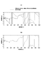
- FIG. 11 shows the difference in phase characteristic between the measured systems obtained from the acoustic characteristics measured by the relative time adjustment of the time measured by the sound output unit 200 and the time measured by the acoustic characteristic measuring apparatus 100.
- An example is shown in contrast to an example of a difference in phase characteristics between measured systems obtained by acoustic characteristics measured without the relative time adjustment.
- FIG. 11A an example of the phase characteristic difference between the measured systems obtained from the acoustic characteristics measured without relative time adjustment is shown by a solid line, and the true phase characteristic is shown. Differences are indicated by dashed lines. Further, in FIG.
- the acoustic characteristic measurement device 100 of the present embodiment measures and measures the relative time of the time measured by the sound output unit 200 and the time measured by the acoustic characteristic measurement device 100.
- required by the acoustic characteristic is shown.
- the recording waveform data #j corresponding to the sound output sequentially performed according to is recorded.
- the acoustic characteristic information of each of the plurality of measured systems can be easily and in a manner capable of accurately detecting the difference in phase characteristics between the acoustic characteristics of the plurality of measured systems, and It can be measured with high accuracy.
- an impulse response reflection waveform obtained with respect to the sound output in the first measured system # 1 in the order of sound output (ii) a sound output position and sound collection in the measured system # 1
- the distance D 1 between the positions (iii) the shortest distance D MIN among the distances between the sound output positions and the sound collection positions in the measured systems # 1 to #N, and (iv) the measured Based on the distance D MAX which is the longest of the distances between the sound output positions and the sound collection positions in the systems # 1 to #N, the recording waveform data extraction section for the system to be measured # 1 is determined. For this reason, it is possible to rationally determine the extraction interval for each of the systems to be measured # 1 to #N.
- a predetermined time schedule is created based on the time required for changing the setting of the measurement target system to the measurement target system whose sound output order is the next. For this reason, the recording process can be performed with a reasonable time schedule.
- the speaker of the sound output unit is arranged at a fixed position.
- the acoustic characteristic measuring device is provided with a sound collection unit.
- the resource is used, and the acoustic characteristic measurement device can be configured without the sound collection unit.
- step S12 the above-described processing of step S12 is performed when determining the extraction section for the system under test # 1.
- the extraction section for the system to be measured # 1 may be determined by another process.
Landscapes
- Physics & Mathematics (AREA)
- Engineering & Computer Science (AREA)
- Acoustics & Sound (AREA)
- General Physics & Mathematics (AREA)
- Signal Processing (AREA)
- Multimedia (AREA)
- Measurement Of Mechanical Vibrations Or Ultrasonic Waves (AREA)
Abstract
録音部(710)が、音出力位置と収音位置との対により定まる複数の被測定系#j(j=1~N)ごとに、所定の時間スケジュールに従って順次行われた音出力に対応した録音波形データ#jを録音する。引き続き、抽出部(730)が、音出力順が2番目以降の被測定系#k(k=2~N)ごとに、インパルス応答反映波形が収まる抽出区間の録音波形データを、音出力順が直前の被測定系#(k-1)における抽出区間、及び、被測定系#kの音出力時刻と被測定系#(k-1)との音出力時刻の差に基づいて抽出する。そして、算出部(740)が、抽出波形データに基づいて、被測定系#jの音響特性情報を算出する。この結果、複数の被測定系の音響特性の相互間における位相特性の差を精度良く検出できる態様で、複数の被測定系のそれぞれの音響特性情報を簡易に、かつ、高精度で測定することができる。
Description
本発明は、音響特性測定装置、音響特性測定方法及び音響特性測定プログラム、並びに、当該音響特性測定プログラムが記録された記録媒体に関する。
従来から、車室内等の所定空間における音響特性の測定を行い、当該測定の結果に基づいて、当該所定空間における音場を制御することが行われている。例えば、特許文献1(以下、「従来例」という)には、次の(i)及び(ii)を行う技術が開示されている。
(i)目標となる音響効果を備えた空間(例えば、コンサートホール)の音響特性を測定するとともに、車室内の音響特性を測定する。
(ii)測定された上記の音響特性の双方を用いて、車室内において、目標となる空間の音響効果を再現する。
(i)目標となる音響効果を備えた空間(例えば、コンサートホール)の音響特性を測定するとともに、車室内の音響特性を測定する。
(ii)測定された上記の音響特性の双方を用いて、車室内において、目標となる空間の音響効果を再現する。
この従来例の技術では、車室内の音響特性測定に際して、車室内に配置されたスピーカから出力されて車室内を伝達した音を、予め定められた位置に配置されたマイクロフォンを利用して録音する。そして、スピーカの配置位置である音出力位置と、マイクロフォンの配置位置である収音位置との対により定まる被測定系の伝達関数を、当該被測定系の音響特性として算出することが記載されている。
かかる音響特性測定では、マイクロフォンによる収音信号Y(t)が、スピーカからの出力音信号X(t)と被測定系のインパルス応答h(t)との畳み込み積分の結果となることを利用している。すなわち、従来例の技術では、出力音信号X(t)としてインパルス信号等を用いた場合の収音信号Y(t)に基づいて、インパルス応答h(t)を算出する。引き続き、インパルス応答h(t)をフーリエ変換して得られる伝達関数H(ω)を、被測定系の音響特性として求めるようになっている。
上述した従来例の技術では、音響特性測定に際して、音出力を行う音出力系と、録音を行う録音系との時刻合わせが高精度で行われることが前提となっている。もし、当該時刻合わせの精度が低いと、測定対象系とした被測定系ごとに、音響特性として測定された伝達関数と真の伝達関数との間で、当該精度の範囲で予測不能な位相特性の差が発生することになる。
このため、従来例の技術により被測定系の音響特性を測定するためには、音出力系と録音系との時刻合わせを高精度で行うことができる構成とすることが必要となる。かかる要請を満たす構成として、音出力系及び録音系の双方を制御する制御部を設け、制御部から音出力開始指令を音出力系及び録音系へ発行するとともに、音出力系が音出力開始指令の受信から遅延無く音出力を行うシステム構成も考えられる。
さて、1系統の録音を行う録音機能、無線通信機能及びこれらの制御機能、並びに、演算処理機能を有する標準的な携帯型装置として、例えばスマートフォン等が広く普及している。かかる標準的な携帯型装置を用いれば、収音位置を手軽に変化させることができるので、便宜である。そして、当該標準的な携帯型装置において、無線通信機能を利用した音出力系への音出力開始指令行うとともに、録音機能動作を開始させるアプリケーションプログラムを実行させることにより、簡易に上述したシステム構成を実現できるように見える。
しかしながら、アプリケーションプログラムによる音出力開始指令の無線通信機能を利用した音出力系への発行は、その時点における基本プログラム(OS)の動作状況に応じて、アプリケーションプログラムにとっては予測できない遅延が発生する。このため、スマートフォン等の標準的な携帯型装置を用いてでは、上述のシステム構成を実現できるとはいえない。
ところで、人間の聴感においては、周波数が250Hz~1kHz以下程度における両耳間位相差が、左右方向における音像定位と関連があることが知られている。このため、スピーカ位置や、スピーカごとに付与する音出力に際して原音信号に付与する遅延時間の設定によって両耳間位相差を制御することにより、音像定位を制御することができる。
かかる両耳間位相差を特定するためには、少なくとも1つのスピーカの位置と、想定聴取位置における人間の右耳位置及び左耳位置のそれぞれとで定まる複数の被測定系ごとの真の伝達関数を測定し、スピーカごとに対応する両耳位相差を算出することが好ましい。しかしながら、被測定系ごとの真の伝達関数ではなくとも、当該複数の被測定系ごとのスピーカからの音出力時点を基準時刻として、基準時刻からの経過時間同士を高精度で合わせた態様で当該複数の被測定系ごとのインパルス応答情報が特定できれば、音響特性として両耳間位相差等の位相特性の差を測定することができる。
このため、複数の被測定系の音響特性の相互間における位相特性の差を精度良く検出できる態様で、複数の被測定系のそれぞれの音響特性情報を簡易に、かつ、高精度で測定する技術が望まれている。かかる要請の応えることが、本発明が解決すべき課題の一つとして挙げられる。
請求項1に記載の発明は、音出力位置と収音位置との対により定まる複数の被測定系ごとに所定の時間スケジュールに従って順次行われた音出力に対応して収録された録音データから、インパルス応答反映波形が収まる抽出区間の録音データを、音出力順が直前の被測定系における抽出区間及び前記直前の被測定系との音出力時刻の差に基づいて抽出する抽出部と;前記抽出区間ごとの録音データに基づいて、前記複数の被測定系ごとの音響特性情報を算出する算出部と;を備えることを特徴とする音響特性測定装置である。
請求項5に記載の発明は、抽出部と;算出部とを備える音響特性測定装置において使用される音響特性測定方法であって、前記抽出部が、音出力位置と収音位置との対により定まる複数の被測定系ごとに所定の時間スケジュールに従って順次行われた音出力に対応して収録された録音データから、インパルス応答反映波形が収まる抽出区間の録音データを、音出力順が直前の被測定系における抽出区間及び前記直前の被測定系との音出力時刻の差に基づいて抽出する抽出工程と;前記算出部が、前記抽出区間ごとの録音データに基づいて、前記複数の被測定系ごとの音響特性情報を算出する算出工程と;を備えることを特徴とする音響特性測定方法である。
請求項6に記載の発明は、音響特性測定装置が有するコンピュータに、請求項5に記載の音響特性測定方法を実行させる、ことを特徴とする音響特性測定プログラムである。
請求項7に記載の発明は、音響特性測定装置が有するコンピュータにより読み取り可能に、請求項6に記載の音響特性測定プログラムが記録されている、ことを特徴とする記録媒体である。
100 … 音響特性測定装置
110 … 処理制御ユニット(録音部の一部、抽出部、算出部)
150 … 収音ユニット(録音部の一部)
700 … 音響特性測定装置
710 … 録音部
730 … 抽出部
740 … 算出部
110 … 処理制御ユニット(録音部の一部、抽出部、算出部)
150 … 収音ユニット(録音部の一部)
700 … 音響特性測定装置
710 … 録音部
730 … 抽出部
740 … 算出部
以下、本発明の一実施形態を、添付図面を参照して説明する。なお、以下の説明及び図面においては、同一又は同等の要素には同一の符号を付し、重複する説明を省略する。
[構成]
図1には、一実施形態に係る音響特性測定装置700の概略的な構成が示されている。この図1に示されるように、音響特性測定装置700は、音響特性測定装置700の外部に配置された音出力部800のスピーカから出力された音を収音するようになっている。本実施形態では、各スピーカの配置位置は固定位置となっている。
図1には、一実施形態に係る音響特性測定装置700の概略的な構成が示されている。この図1に示されるように、音響特性測定装置700は、音響特性測定装置700の外部に配置された音出力部800のスピーカから出力された音を収音するようになっている。本実施形態では、各スピーカの配置位置は固定位置となっている。
なお、スピーカの数は、1個であってもよいし、2個以上あってもよい。
音響特性測定置700は、録音部710と、記憶部720とを備えている。また、音響特性測定置700は、抽出部730と、算出部740とを備えている。
上記の録音部710は、1個のマイクロフォンMCと、計時機構とを備えている。録音部710では、不図示の入力部により録音開始が指定されると録音処理を開始する。かかる録音処理に際して、録音部710では、入力部により録音中断が指定されるまで、マイクロフォンMCにより収音された音の振幅が、所定サンプル周波数でサンプルされ、デジタル値に変換される。この変換の結果は録音波形データとして記憶部720へ送られる。
なお、本実施形態では、音出力位置(音出力するスピーカの配置位置)と、収音位置(マイクロフォンMCの配置位置)との対により被測定系が定まるようになっている。そして、後述する予め定められた時間スケジュールに従って、被測定系ごとの音出力が順次行われる。
なお、以下の説明においては、被測定系のそれぞれを、時間スケジュールに従って音出力を行う順に、被測定系#1、被測定系#2、…、被測定系#Nと記すものとする。また、被測定系#j(j=1,…,N)における出力音信号を「Xj(t)」と記すものとする。
上記の記憶部720には、様々な情報が記録される。こうした情報には、測定条件情報、録音データ、抽出データ及び音響特性情報が含まれている。
測定条件情報には、被測定系情報及び時間スケジュールが含まれる。本実施形態では、被測定系情報には、被測定系#j(j=1,2,…,N)における音出力位置、収音位置、及び、音出力位置と収音位置との間の距離が含まれている。なお、固定位置に配置されたスピーカの数が1個である場合には、被測定系#1~#jの全てにおける音出力位置が同一となる。
また、時間スケジュールには、被測定系#(k-1)(k=2,…,N)からの音出力時刻と、被測定系#kからの音出力時刻との時刻差Tk,k+1が含まれている。なお、時刻差Tk,k+1は、被測定系#(k-1)から被測定系#kへの測定対象系の変更の設定に要すると考えられる時間に基づいて、予め定められる。
録音データには、被測定系#jごとの録音開始時刻及び録音波形データが含まれている。また、抽出データには、被測定系#jごとの抽出波形データが含まれている。さらに、音響特性情報には、被測定系#jごとの音響特性情報が含まれている。
上記の抽出部730は、被測定系#jに関する抽出区間を算出する。引き続き、抽出部730は、算出された抽出区間の録音波形データを抽出波形データ#jとして抽出する。そして、抽出部730は、抽出された抽出波形データ#jを記憶部720に格納する。
なお、抽出部730による抽出処理については、後述する。
上記の算出部740は、抽出波形データ#jに基づいて、音響特性情報を算出する。そして、算出部740は、算出された音響特性情報を記憶部720に格納する。
なお、算出部740による音響特性情報の算出処理については、後述する。
[動作]
次に、上記のように構成された音響特性測定装置700の動作について説明する。
次に、上記のように構成された音響特性測定装置700の動作について説明する。
<録音処理>
音響特性測定装置700は、音響特性測定に際して、まず、録音処理を行う。かかる録音処理では、被測定系#1,被測定系#2,…,被測定系#Nの順で、被測定系ごとの録音処理を行う。
音響特性測定装置700は、音響特性測定に際して、まず、録音処理を行う。かかる録音処理では、被測定系#1,被測定系#2,…,被測定系#Nの順で、被測定系ごとの録音処理を行う。
被測定系#1に関する録音では、まず、マイクロフォンMCが被測定系#1に対応する収音位置に配置される。引き続き、入力部を利用した録音開始が録音部710に対して指定されると、録音部710が録音処理を開始する。
次に、音出力部800に対して、音出力開始の指定がなされる。この結果、音出力部800からは、まず、被測定系#1に対応する音出力位置から出力音信号X1(t)に対応する音出力が行われた後、時間スケジュールに従って、被測定系#kに対応する音出力位置から出力音信号Xk(t)に対応する音出力が行われる。
録音部710は、被測定系#1に関する録音処理に際して、録音開始の指定を受けると、まず、録音部710内部における計時機構を利用して、被測定系#1に関する録音開始時刻trs1を検出する。そして、録音部710は、検出された録音開始時刻trs1を、被測定系#1のための録音データ領域の先頭データとして、記憶部720に格納する。
引き続き、録音部710は、マイクロフォンMCにより収音された音の振幅を、所定サンプル周波数でサンプルし、デジタル値に変換する。そして、録音部710は、変換結果を、録音波形データ#1として、記憶部720内の被測定系#1のための録音データ領域に格納する。
出力音信号X1(t)に対応する音出力が行われた後に、インパルス応答反映情報h1(t)の検出のために十分な時間が経過した後に、入力部を利用した録音中断が録音部710に対して指定されると、録音部710は録音を中断する。そして、次の測定対象系である被測定系#k(この段階では、k=2=1+1)の設定を行う。
なお、被測定系#kが、例えば、被測定系#(k-1)と比べて、収音位置のみが異なる場合には、被測定系#kへの設定の変更に際して、マイクロフォンMCの配置位置の変更のみが行われる。
この後、録音部710は、録音開始の指定を受けると、上述した被測定系#1の場合と同様に、録音処理を実行して、被測定系#kの録音開始時刻及び録音波形データ#kとして、記憶部720内の被測定系#kのための録音データ領域に格納する。以後、被測定系の設定変更を行いつつ、被測定系#Nに関する録音処理が終了するまで、上述した被測定系#1の場合と同様に、録音処理を実行する。
なお、録音部710による録音処理は、出力音信号Xj(t)に対応する音出力以外は、静謐な音環境において行われる。
<抽出処理>
上記の録音処理が終了すると、音響特性測定装置700では、抽出部730が、抽出処理を開始する。
上記の録音処理が終了すると、音響特性測定装置700では、抽出部730が、抽出処理を開始する。
かかる抽出処理に際して、抽出部730は、まず、記憶部720内の被測定系#1のための録音データ領域のデータを読み取る。引き続き、抽出部730は、読み取られた録音開始時刻trs1及び録音波形データ#1、並びに、記憶部720における距離D1~DNの中の最短距離DMIN及び最長距離DMAXに基づいて、抽出区間[tes1,tee1]を決定する。ここで、時刻tes1は、当該抽出区間の開始時刻である。また、時刻tee1は、当該抽出区間の終了時刻である。
本実施形態では、抽出部730は、録音波形データ#1における最大値に応じて定められる閾値に最初に到達した閾値到達時刻を検出する。引き続き、抽出部730は、閾値到達時刻前に最初に有効な振幅を有するようになった時刻と、距離D1と最短距離DMINとの差とに基づいて、時刻tes1を算出する。また、抽出部730は、閾値到達時刻後に最初に有効な振幅を有さなくなった時刻と、距離D1と最大距離DMAXとの差とに基づいて、時刻tee1を算出する。
次に、抽出部730は、録音波形データ#1の中から、抽出区間[tes1,tee1]のデータを抽出する。そして、抽出部730は、抽出されたデータを、抽出波形データ#1として、記憶部720内の被測定系#1のための抽出データ領域に格納する。
次いで、抽出部730は、被測定系#2~#Nのそれぞれについて、順次、抽出区間[tesk,teek]の算出、及び、録音波形データ#kの中からの抽出区間[tesk,teek]のデータの抽出を行う。そして、抽出部730は、被測定系#kに関する抽出波形データを記憶部720内の被測定系#kのための抽出データ領域へ格納する。
ここで、抽出部730は、次の(1),(2)式により、時刻tesk,teekを算出する。
tesk=tesk-1+Tk-1,k …(1)
teek=teek-1+Tk-1,k …(2)
tesk=tesk-1+Tk-1,k …(1)
teek=teek-1+Tk-1,k …(2)
<算出処理>
上記の抽出処理が終了すると、音響特性測定装置700では、算出部740が、被測定系#jの音響特性情報の算出処理を開始する。
上記の抽出処理が終了すると、音響特性測定装置700では、算出部740が、被測定系#jの音響特性情報の算出処理を開始する。
かかる算出処理に際して、算出部740は、まず、記憶部720内の被測定系#j(j=1~N)のための抽出データ領域から抽出波形データ#jを読み取る。引き続き、算出部740は、読み取られた抽出波形データ#jに基づいて、被測定系#jの音出力開始時刻が時刻tee1であるとして、インパルス応答反映情報hj(t)を周知の手法により算出する。なお、かかる周知の手法の一例が、上述した従来例に開示されている。
こうして算出されたインパルス応答反映情報hj(t)、被測定系#jのインパルス応答を時間方向に沿って、被測定系#1~#Nの全てに共通の移動時間だけずらしたものとなっている。
次に、算出部740は、インパルス応答反映情報hj(t)に対してフーリエ変換を施して、被測定系#jの音響特性情報として、伝達関数情報Hj(ω)を算出する。そして、算出部740は、算出された伝達関数情報Hj(ω)を、記憶部720内の被測定系#jのための音響特性情報領域に格納する。
以上のようにして算出された伝達関数情報Hj(ω)は、被測定系#jの真の伝達関数と比べて、位相特性のみが異なっている。そして、伝達関数情報Hj(ω)と真の伝達関数との位相特性の差異は、被測定系#1~#Nの全てで共通したものとなっている。このため、伝達関数情報Hj(ω)は、被測定系#jにおける真の減衰特性を反映するとともに、伝達関数情報Hq(ω)と伝達関数情報Hr(ω)(q≠r)との位相特性の差異は、被測定系#q,#rの真の伝達関数間の位相特性の差異を反映している。
こうして算出された伝達関数情報Hj(ω)は、不図示の通信部を介して、不図示の音響特性制御装置へ送信される。そして、音響特性制御装置は、伝達関数情報Hj(ω)を利用することにより、精度の高い音像定位のための音響特性の制御を行う。
以上説明したように、本実施形態では、録音部710が、音出力位置と収音位置との対により定まる複数の被測定系#j(j=1~N)ごとに、所定の時間スケジュールに従って順次行われた音出力に対応した録音波形データ#jを収録する。引き続き、抽出部730が、音出力順が2番目以降の被測定系#k(k=2~N)ごとに、インパルス応答反映波形が収まる抽出区間[tesk,teek]の録音波形データを、音出力順が直前の被測定系#(k-1)における抽出区間[tesk-1,teek-1]、及び、被測定系#kの音出力時刻と被測定系#(k-1)との音出力時刻の差Tk-1,kに基づいて抽出する。そして、算出部740が、抽出区間[tesj,teej]ごとの抽出波形データに基づいて、被測定系#jの伝達関数情報Hj(ω)を、被測定系#jの音響特性情報として算出する。
したがって、本実施形態によれば、複数の被測定系の音響特性の相互間における位相特性の差を精度良く検出できる態様で、複数の被測定系のそれぞれの音響特性情報を簡易に、かつ、高精度で測定することができる。
また、本実施形態では、(i)音出力順が最初の被測定系#1における音出力に対して得られたインパルス応答反映波形、(ii)被測定系#1における音出力位置と収音位置との間の距離D1、(iii)被測定系#1~#Nにおける音出力位置と収音位置との間の距離のうちで最短である距離DMIN、及び、(iv)被測定系#1~#Nにおける音出力位置と収音位置との間の距離のうちで最長である距離DMAXに基づいて、被測定系#1に関する録音波形データの抽出区間を決定する。このため、被測定系#1~#Nのそれぞれに関する抽出区間を合理的に決定することができる。
また、本実施形態では、所定の時間スケジュールが、音出力順が次の被測定系への測定対象系の設定変更に要する時間に基づいて作成される。このため、合理的な時間スケジュールで録音処理を行うことができる。
<実施形態の変形>
上記の実施形態に対しては、様々な変形を行うことができる。
上記の実施形態に対しては、様々な変形を行うことができる。
例えば、上記の実施形態では、音出力部のスピーカが固定位置に配置されるものとした。これに対して、音出力部のスピーカの配置位置を変更できるようにしてもよい。
また、上記の実施形態では、音響特性測定装置が録音部を備えるようにした。これに対し、録音部の機能を果たすことができる資源が既に存在する場合には、当該資源を利用するようにし、音響特性測定装置を、録音部を備えない構成とすることができる。
なお、上記の実施形態の音響特性測定装置700の抽出部730及び算出部740の一部又は全部を、中央処理装置(CPU:Central Processing Unit)等を備えた演算部としてのコンピュータとして構成し、予め用意されたプログラムを当該コンピュータで実行することにより、抽出部730及び算出部740の一部又は全部の機能を果たすようにしてもよい。このプログラムはハードディスク、CD-ROM、DVD等のコンピュータで読み取り可能な記録媒体に記録され、当該コンピュータによって記録媒体からロードされて実行される。また、このプログラムは、CD-ROM、DVD等の可搬型記録媒体に記録された形態で取得されるようにしてもよいし、インターネットなどのネットワークを介した配信の形態で取得されるようにしてもよい。
以下、本発明の一実施例を、図2~図11を参照して説明する。なお、以下の説明及び図面においては、同一又は同等の要素については同一の符号を付し、重複する説明を省略する。
[構成]
図2には、一実施例に係る音響特性測定装置100の概略的な構成が示されている。なお、音響特性測定装置100は、上述した第1実施形態の音響特性測定装置700(図1参照)の一態様となっている。
[構成]
図2には、一実施例に係る音響特性測定装置100の概略的な構成が示されている。なお、音響特性測定装置100は、上述した第1実施形態の音響特性測定装置700(図1参照)の一態様となっている。
図2に示されるように、音響特性測定装置100の外部に配置された音出力ユニット200のスピーカから出力された音を録音するようになっている。この音出力ユニット200におけるスピーカの数は、上述した音出力部800の場合と同様に、1個であってもよいし、2個以上あってもよい。また、音出力ユニット200における各スピーカの配置位置は、音出力部800と同様に、固定位置となっている。すなわち、本実施例における音出力ユニット200は、上述した実施形態における音出力部の機能を果たすようになっている。
音響特性測定置100は、処理制御ユニット110と、記憶ユニット120と、入力ユニット130とを備えている。また、音響特性測定装置100は、表示ユニット140と、収音ユニット150と、無線通信ユニット160とを備えている。
上記の処理制御ユニット110は、音響特性測定装置100の全体を統括制御するとともに、様々な処理を行う。この処理制御ユニット110については、後述する。
上記の記憶ユニット120は、不揮発性の記憶素子を備えて構成され、音響特性測定装置100において利用される様々な情報データが記憶される。こうした情報データには、測定条件情報MCI、録音データRCD、抽出データETD及び音響特性情報SCIが含まれている。すなわち、記憶ユニット120は、上述した実施形態における記憶部720の機能を果たすようになっている。
なお、記憶ユニット120に記憶される測定条件情報MCI、録音データRCD、抽出データETD及び音響特性情報SCIの内容については、後述する。
上記の入力ユニット130は、音響特性測定装置100の本体部に設けられたキー部、及び/又はキー部を備えるリモート入力装置等により構成される。ここで、本体部に設けられたキー部としては、表示ユニット140の表示デバイスに設けられたタッチパネルを用いることができる。なお、キー部を有する構成に代えて、又は併用して音声認識技術を利用して音声にて入力する構成を採用することもできる。
この入力ユニット130を利用者が操作することにより、音響特性測定装置100の処理内容の指定が行われる。こうした指定には、処理制御ユニット110による録音開始指定や、録音中断指定等が含まれる。すなわち、入力ユニット140は、上述した実施形態における入力部の機能を果たすようになっている。
上記の表示ユニット140は、処理制御ユニット110から送られた画像データを受ける。そして、表示ユニット140は、当該画像データに対応する画像を表示する。こうして表示ユニット140に表示される画像には、音響特性測定装置100における音響特性測定における測定段階のそれぞれを提示する画像や、測定段階のそれぞれにおいて次に行うべき操作のガイダンスを提示する画像等が含まれている。
上記の収音ユニット150は、1個のマイクロフォンMCを備えて構成されている。収音ユニット150では、処理制御ユニット110により録音開始が指定されると、録音処理を開始する。かかる録音処理に際して、収音ユニット150では、入力部により録音中断が指定されるまで、マイクロフォンMCにより収音された音の振幅が、所定サンプル周波数でサンプルされ、デジタル値に変換される。この変換の結果は録音波形データとして処理制御ユニット110へ送られる。すなわち、収音ユニット150は、上述した実施形態における録音部710の一部の機能を果たすようになっている。
上記の無線通信ユニット160は、処理制御ユニット110による制御のもとで、外部の音響特性制御装置との通信を行う。処理制御ユニット110は、無線通信ユニット160を利用することにより、音響特性制御装置から新たな測定条件情報を受信したり、音響特性制御装置へ音響特性の測定結果を送信したりする。
次に、上記の処理制御ユニット110について説明する。この処理制御ユニット110は、中央処理装置(CPU)及び周辺回路(計時機構を含む)を備えて構成されている。処理制御ユニット110が様々なプログラムを実行することにより、音響特性測定装置100としての各種機能が実現されるようになっている。こうした機能の中には、上述した実施形態における抽出部730及び算出部740の機能も含まれている。
また、処理制御ユニット110は、無線通信ユニット160を利用して、新たな音響特性測定の測定条件情報を音響特性制御装置から受信する。そして、処理制御ユニット110は、新たに受信した測定条件情報を、測定条件情報MCIとして、記憶ユニット120へ格納する。
また、処理制御ユニット110は、記憶ユニット120内の測定条件情報MCIに従って、音響特性の測定処理を行う。かかる測定処理に、録音処理、抽出処理、及び、音響特性の算出処理が含まれている。また、当該測定処理には、録音処理における操作ガイダンスの画像の作成処理が含まれている。
また、処理制御ユニット110は、無線通信ユニット160を利用して、音響特性の測定結果を、音響特性制御装置へ送信する。
なお、処理制御ユニット110が実行するプログラムはハードディスク、CD-ROM、DVD等のコンピュータで読み取り可能な記録媒体に記録され、当該記録媒体からロードされて実行される。また、このプログラムは、CD-ROM、DVD等の可搬型記録媒体に記録された形態で取得されるようにしてもよいし、インターネットなどのネットワークを介した配信の形態で取得されるようにしてもよい。
<測定条件情報MCI、録音データRCD、抽出データETD、音響特性情報SCI>
次いで、記憶ユニット120に記憶される測定条件情報MCI、録音データRCD、抽出データETD及び音響特性情報SCIの内容について説明する。
次いで、記憶ユニット120に記憶される測定条件情報MCI、録音データRCD、抽出データETD及び音響特性情報SCIの内容について説明する。
測定条件情報MCIには、図3に示されるように、被測定系情報と時間スケジュールとが含まれている。ここで、被測定系情報には、被測定系#j(j=1,2,…,N)における音出力位置PSj、収音位置PMj、及び、音出力位置PSjと収音位置PMjとの間の距離Djが含まれている。なお、固定位置に配置されたスピーカの数が1個である場合には、音出力位置PSjの全てが同一となる。
また、時間スケジュールには、被測定系#(k-1)(k=2,…,N)からの音出力時刻と、被測定系#kからの音出力時刻との時刻差Tk-1,kが含まれている。かかる時間スケジュールに従って音出力が行われた場合の音出力タイミングが、図4に示されている。
なお、時刻差Tk-1,kは、被測定系#(k-1)から被測定系#kへの測定対象系の変更の設定に要すると考えられる時間に基づいて、予め定められる。
録音データRCDには、図5(A)に示されるように、被測定系#jごとの録音波形データ#jが含まれている。また、抽出データETDには、図5(B)に示されるように、被測定系#jごとの録音波形データ#jから抽出された抽出波形データ#jが含まれている。さらに、音響特性情報SCIには、被測定系#jごとの音響特性情報である伝達関数情報Hj(ω)(ω:角周波数))が含まれている。
[動作]
次に、上記のように構成された音響特性測定装置100の動作について、処理制御ユニット110による録音処理、抽出処理、及び、音響特性の算出処理に主に着目して説明する。なお、音響特性測定の測定条件情報は、既に、記憶ユニット120内に、測定条件情報MCIとして記憶されているものとする。
次に、上記のように構成された音響特性測定装置100の動作について、処理制御ユニット110による録音処理、抽出処理、及び、音響特性の算出処理に主に着目して説明する。なお、音響特性測定の測定条件情報は、既に、記憶ユニット120内に、測定条件情報MCIとして記憶されているものとする。
<録音処理>
音響特性測定装置100は、音響特性測定に際して、まず、録音処理を行う。かかる録音処理では、被測定系#1,被測定系#2,…,被測定系#Nの順で、被測定系ごとの録音処理を行う。
音響特性測定装置100は、音響特性測定に際して、まず、録音処理を行う。かかる録音処理では、被測定系#1,被測定系#2,…,被測定系#Nの順で、被測定系ごとの録音処理を行う。
被測定系#1に関する録音では、まず、マイクロフォンMCが収音位置PM1に配置される。引き続き、入力ユニット130から録音開始指定を受けると、処理制御ユニット110は、被測定系#1に関する録音処理を開始する。かかる被測定系#1に関する録音処理に際して、処理制御ユニット110は、まず、計時機構を利用して、被測定系#1に関する録音開始時刻trs1を検出する。引き続き、処理制御ユニット110は、検出された録音開始時刻trs1を、被測定系#1のための録音データ領域の先頭データとして、記憶ユニット120内に格納する。そして、処理制御ユニット110は、収音ユニット150から順次送られてくる振幅データの収集を開始し、収集された振幅データを記憶ユニット120内の被測定系#1のための録音データ領域に順次格納する。
処理制御ユニット110による被測定系#1に関する録音処理の実行中に、音出力ユニット200に対して、音出力開始の指定がなされる。この結果、音出力ユニット200から、まず、被測定系#1に対応するスピーカからの出力音信号X1(t)に対応する音出力が行われる。この後、上述した時間スケジュールに従って、上述した図4に示されるタイミングで被測定系#kに対応するスピーカからの出力音信号Xk(t)に対応する音出力が自動的に行われる。
出力音信号X1(t)に対応する音出力が行われた後に、インパルス応答情報h1(t)の検出のために十分な時間が経過した後に、入力ユニット130から録音開始指定を受けると、処理制御ユニット110は、録音処理を中断する。そして、次の測定対象系である被測定系#k(この段階では、k=2=1+1)の設定が行われる。
なお、被測定系#kが、例えば、被測定系#(k-1)と比べて、収音位置のみが異なる場合には、被測定系#kへの設定の変更に際して、マイクロフォンMCの配置位置の変更のみが行われる。
この後、処理制御ユニット110は、録音開始指定を受けると、上述した被測定系#1の場合と同様に、録音処理を実行して、被測定系#kの録音開始時刻trsk及び録音波形データ#kとして、記憶ユニット120内の被測定系#kのための録音データ領域に格納する。以後、被測定系の設定変更を行いつつ、被測定系#Nに関する録音処理が終了するまで、上述した被測定系#1の場合と同様に、録音処理が実行される。
図6には、被測定系#jに関する録音開始時刻trsjと録音終了時刻trejとの例が、上述した図5に示した音出力ユニット200からの音出力タイミングと対比して示されている。この図6に示されるように、音出力ユニット200内の計時機構と音響特性測定装置100内の計時機構との間では高精度の時刻合わせが行われていないので、被測定系#jに関する音出力時刻と録音開始時刻との差異(τj)は、一般に、被測定系間で異なっている。
なお、処理制御ユニット110による録音処理は、出力音信号Xj(t)に対応する音出力以外は、静謐な音環境において行われる。
<抽出処理及び算出処理>
上記の録音処理が終了すると、音響特性測定装置100では、処理制御ユニット110が、抽出処理を開始する。
上記の録音処理が終了すると、音響特性測定装置100では、処理制御ユニット110が、抽出処理を開始する。
かかる録音処理に際しては、図7に示されるように、まず、ステップS11において、処理制御ユニット110が、パラメータpの値を「1」に設定する。引き続き、ステップS12において、処理制御ユニット110が、被測定系#1に関する抽出区間[tes1,tee1]の決定、すなわち、被測定系#1に関する抽出の開始時刻tes1及び終了時刻tee1を決定する。
なお、ステップS12における開始時刻tes1及び終了時刻tee1の決定処理の詳細については、後述する。
次に、ステップS13において、処理制御ユニット110は、録音波形データ#1の中から、抽出区間[tes1,tee1]のデータ[Y1(tesj),…,Y1(teej)]を抽出する。そして、処理制御ユニット110は、抽出されたデータ[Y1(tesj),…,Y1(teej)]を、抽出波形データ#1として、記憶ユニット120内の被測定系#1のための抽出データ領域に格納する。
次いで、ステップS14において、処理制御ユニット110が、パラメータpの値をインクリメント(「1」加算)する。引き続き、ステップS15において、処理制御ユニット110が、被測定系#1に関する抽出区間[tesp,teep]の決定、すなわち、被測定系#pに関する抽出の開始時刻tesp及び終了時刻teepを、上述した(1),(2)式により算出する。
次に、ステップS16において、処理制御ユニット110が、録音波形データ#pの中から、抽出区間[tesp,teep]のデータ[Yp(tesp),…,Yp(teep)]を抽出する。そして、処理制御ユニット110は、抽出されたデータ[Yp(tesp),…,Yp(teep)]を、抽出波形データ#pとして、記憶ユニット120内の被測定系#pのための抽出データ領域に格納する。
引き続き、ステップS17において、処理制御ユニット110が、パラメータpの値が「N」となっているか否かを判定することにより、被測定系#1~#Nの全てについての抽出処理を終了したか否かを判定する。ステップS17における判定の結果が否定的であった場合(ステップS17:N)には、処理はステップS14へ戻る。そして、ステップS17における判定の結果が肯定的となるまで、ステップS14~S17の処理が繰り返される。
被測定系#1~#Nの全てについての抽出処理を終了し、ステップS17における判定の結果が肯定的となると(ステップS17:Y)、ステップS18へ進む。このステップS18では、処理制御ユニット110が、被測定系#jの音響特性情報として、伝達関数情報Hj(ω)を算出する。
なお、図8には、被測定系#jに関する抽出区間の開始時刻tesjと終了時刻teejとの例が、上述した図5に示した音出力ユニット200からの音出力タイミングと対比して示されている。この図8に示されるように、音出力ユニット200内の計時機構と音響特性測定装置100内の計時機構との間では高精度の時刻合わせが行われていないが、被測定系#jに関する音出力時刻と抽出区間の開始時刻との差異(τ0)は、被測定系間で共通となっている。すなわち、被測定系間において、各被測定系に関する音出力開始時刻を基準時刻として、基準時刻以降についての相対的な時刻合わせが行われているといえる。
なお、以下の説明においては、抽出波形データ#jに対応する波形を「Yj(t)」と記すものとする。
ステップS18における算出処理では、処理制御ユニット110が、まず、記憶ユニット120内の被測定系#jのための抽出データ領域から抽出波形データ#j[Yj(tesj),…,Yj(teej)]を読み取る。引き続き、処理制御ユニット110は、読み取られた抽出波形データ#jに基づき、被測定系#jにおける音出力ユニット200からの音出力の開始時刻が「時刻tesj」であるとして、インパルス応答反映情報hj(t)を算出する。
こうして算出されたインパルス応答反映情報hj(t)は、被測定系#jのインパルス応答を時間方向に沿って、被測定系#1~#Nの全てに共通の移動時間(時間τ0)だけずらしたものとなっている。
次に、処理制御ユニット110は、インパルス応答反映情報hj(t)に対してフーリエ変換を施して、被測定系#jの音響特性情報として、伝達関数情報Hj(ω)を算出する。そして、処理制御ユニット110は、算出された伝達関数情報Hj(ω)を、記憶ユニット120内の被測定系#jのための音響特性情報領域に格納する。
以上のようにして算出された伝達関数情報Hj(ω)は、被測定系#jの真の伝達関数と比べて、位相特性のみが異なっている。そして、伝達関数情報Hj(ω)と真の伝達関数との位相特性の差異は、被測定系#1~#Nの全てで共通したものとなっている。このため、伝達関数情報Hj(ω)は、被測定系#jにおける真の減衰特性を反映するとともに、伝達関数情報Hq(ω)と伝達関数情報Hr(ω)(q≠r)との位相特性の差異は、被測定系#q,#rの真の伝達関数間の位相特性の差異を反映している。
以上のようにして伝達関数情報Hj(ω)が算出されると、処理制御ユニット110は、無線通信ユニット160を利用して、音響特性制御装置へ送信する。そして、音響特性制御装置は、伝達関数情報Hj(ω)を利用することにより、精度の高い音像定位のための音響特性の制御を行う。
<開始時刻tes1及び終了時刻tee1の決定処理>
次に、ステップS12における開始時刻tes1及び終了時刻tee1の決定処理について説明する。
次に、ステップS12における開始時刻tes1及び終了時刻tee1の決定処理について説明する。
かかる決定処理に際しては、図9に示されるように、まず、ステップS21において、処理制御ユニット110が、録音波形データ#1[Y1(trs1),…,Y1(tre1)]における最大値の所定数L分の1を閾値ATHとする。そして、処理制御ユニット110は、当該閾値ATHに最初に到達した閾値到達時刻tTHを検出する。なお、「所定数L」は、抽出区間を的確に定めるという観点から、実験、シミュレーション、経験等に基づいて、予め定められる。
引き続き、ステップS22において、処理制御ユニット110が、被測定系#1に関する抽出区間の開始時刻tes1を算出する。かかる時刻tes1の算出に際して、処理制御ユニット110は、まず、録音区間[trs1,tre1]における各時点の波形Y1(t)(trs1≦t≦tre1)の2乗積分値I(t)を、次の(3)式により算出する。
I(t)=(Y1(trs1))2+…+(Y1(tre1))2 …(3)
I(t)=(Y1(trs1))2+…+(Y1(tre1))2 …(3)
次に、処理制御ユニット110は、「1」と比べて十分小さい値を、閾値Rとして定義する。本実施例では、閾値Rを、「1/1000」としている。
引き続き、処理制御ユニット110は、次の(4)式の条件を最初に満たした時刻tFを検出する。
I(tF)/I(tre1)≧R …(4)
I(tF)/I(tre1)≧R …(4)
次いで、処理制御ユニット110は、被測定系#1に関する抽出区間の開始時刻tes1を算出する。かかる時刻tes1の算出に際して、処理制御ユニット110は、まず、距離D1と、距離D1,D2,…,DNの中における最短値DMINとの差ΔMINを、次の(5)式により算出する。
ΔMIN=D1-DMIN …(5)
ΔMIN=D1-DMIN …(5)
引き続き、処理制御ユニット110は、常温かつ常圧の場合の音速C、及び、所定マージン時間TΔ(>0)を用いて、抽出区間の開始時刻tes1を、次の(6)式により算出する。
tes1=tF-TF(=(ΔMIN/C)+TΔ) …(6)
tes1=tF-TF(=(ΔMIN/C)+TΔ) …(6)
なお、所定マージン時間TΔは、被測定系における温度及び気圧の常温及び常圧からの最大想定変動量に基づいて、予め定められる。
次に、ステップS23において、処理制御ユニット110が、被測定系#1に関する抽出区間の終了時刻tee1を算出する。かかる時刻tee1の算出に際して、処理制御ユニット110は、次の(7)式の条件を最初に満たした時刻tBを検出する。
(I(tre1)-I(tB))/I(tre1)≦R …(7)
(I(tre1)-I(tB))/I(tre1)≦R …(7)
次いで、処理制御ユニット110は、被測定系#1に関する抽出区間の終了時刻tee1を算出する。かかる時刻tee1の算出に際して、処理制御ユニット110は、まず、距離D1,D2,…,DNの中における最長値DMAXと、距離D1との差ΔMAXを、次の(8)式により算出する。
ΔMAX=D1-DMAX …(8)
ΔMAX=D1-DMAX …(8)
引き続き、処理制御ユニット110は、抽出区間の終了時刻tee1を、次の(9)式により算出する。
tee1=tB+TB(=(ΔMAX/C)+TΔ) …(9)
tee1=tB+TB(=(ΔMAX/C)+TΔ) …(9)
こうしてステップS23の処理が終了すると、ステップS12の処理が終了する。そして、処理は、上述した図7におけるステップS13へ進む。
なお、図10には、ステップS12における開始時刻tes1及び終了時刻tee1の決定処理により算出される時刻と、被測定系#1に関する録音波形Y1(t)及び2乗積分値I(t)との関係の例が示されている。
図11には、音出力ユニット200における計時時刻と音響特性測定装置100との計時時刻との相対的な時刻合わせがなされて測定された音響特性により求められる被測定系間における位相特性の差の例が、当該相対的な時刻合わせがなされずに測定された音響特性により求められる被測定系間における位相特性の差の例と対比して示されている。ここで、図11(A)には、相対的な時刻合わせがなされずに測定された音響特性により求められる被測定系間における位相特性の差の例が実線で示され、真の位相特性の差が破線で示されている。また、図11(B)には、本実施例の音響特性測定装置100により、音出力ユニット200における計時時刻と音響特性測定装置100との計時時刻との相対的な時刻合わせがなされて測定された音響特性により求められる被測定系間における位相特性の差の例が示されている。
図11(A)に示されるように、音出力ユニット200における計時時刻と音響特性測定装置100との計時時刻との相対的な時刻合わせがなされない場合には、測定された音響特性により求められる被測定系間における位相特性の差が、真の位相特性の差と高精度で一致することは保証されない。これに対し、図11(A)において破線で示される真の位相特性の差と、図11(B)において実線で示される本実施例の音響特性測定装置100による測定結果から求められる被測定系間における位相特性の差は、高精度で一致する。
以上説明したように、本実施例では、処理制御ユニット110が、音出力位置と収音位置との対により定まる複数の被測定系#j(j=1~N)ごとに、所定の時間スケジュールに従って順次行われた音出力に対応した録音波形データ#jを収録する。引き続き、処理制御ユニット110が、音出力順が2番目以降の被測定系#k(k=2~N)ごとに、インパルス応答反映波形が収まる抽出区間[tesk,teek]の録音波形データを、音出力順が直前の被測定系#(k-1)における抽出区間[tesk-1,teek-1]、及び、被測定系#kの音出力時刻と被測定系#(k-1)との音出力時刻の差Tk-1,kに基づいて抽出する。そして、処理制御ユニット110が、抽出区間[tesj,teej]ごとの抽出波形データ#jに基づいて、被測定系#jの伝達関数情報Hj(ω)を、被測定系#jの音響特性情報として算出する。
したがって、本実施例によれば、複数の被測定系の音響特性の相互間における位相特性の差を精度良く検出できる態様で、複数の被測定系のそれぞれの音響特性情報を簡易に、かつ、高精度で測定することができる。
また、本実施例では、(i)音出力順が最初の被測定系#1における音出力に対して得られたインパルス応答反映波形、(ii)被測定系#1における音出力位置と収音位置との間の距離D1、(iii)被測定系#1~#Nにおける音出力位置と収音位置との間の距離のうちで最短である距離DMIN、及び、(iv)被測定系#1~#Nにおける音出力位置と収音位置との間の距離のうちで最長である距離DMAXに基づいて、被測定系#1に関する録音波形データの抽出区間を決定する。このため、被測定系#1~#Nのそれぞれに関する抽出区間を合理的に決定することができる。
また、本実施例では、所定の時間スケジュールが、音出力順が次の被測定系への測定対象系の設定変更に要する時間に基づいて作成される。このため、合理的な時間スケジュールで録音処理を行うことができる。
<実施例の変形>
上記の実施形態に対しては、様々な変形を行うことができる。
上記の実施形態に対しては、様々な変形を行うことができる。
例えば、上記の実施例では、音出力ユニットのスピーカが固定位置に配置されるものとした。これに対して、音出力ユニットのスピーカの配置位置を変更できるようにしてもよい。
また、上記の実施例では、音響特性測定装置が収音ユニットを備えるようにした。これに対し、収音ユニットの機能を果たすことができる資源が既に存在する場合には、当該資源を利用するようにし、音響特性測定装置を、収音ユニットを備えない構成とすることができる。
また、上記の実施例では、被測定系#1に関する抽出区間の決定に際して、上述したステップS12の処理を行うようにした。これに対し、時刻差Tk-1,k(k=2~N)を用いつつ、被測定系#1~#Nの全てについて、音出力時刻と録音開始時刻との差異(τ0)を被測定系間で共通にすることができ、かつ、有効な抽出波形データを抽出可能とする処理であれば、他の処理により被測定系#1に関する抽出区間を決定するようにしてもよい。
Claims (7)
- 音出力位置と収音位置との対により定まる複数の被測定系ごとに所定の時間スケジュールに従って順次行われた音出力に対応して収録された録音データから、インパルス応答反映波形が収まる抽出区間の録音データを、音出力順が直前の被測定系における抽出区間及び前記直前の被測定系との音出力時刻の差に基づいて抽出する抽出部と;
前記抽出区間ごとの録音データに基づいて、前記複数の被測定系ごとの音響特性情報を算出する算出部と;
を備えることを特徴とする音響特性測定装置。 - 前記抽出部は、
音出力順が最初の被測定系における音出力に対して得られたインパルス応答反映波形、前記最初の被測定系における音出力位置と収音位置との間の距離、前記複数の被測定系における音出力位置と収音位置との間の距離のうちで最短である距離、及び、前記複数の被測定系における音出力位置と収音位置との間の距離のうちで最長である距離に基づいて、前記最初の被測定系に関する録音データの抽出区間を決定し、
前記決定された抽出区間における録音データを抽出する、
ことを特徴とする請求項1に記載の音響特性測定装置。 - 前記所定の時間スケジュールは、音出力順が次の被測定系への測定対象系の設定変更に要する時間に基づいて作成される、ことを特徴とする請求項1に記載の音響特性測定装置。
- 前記録音データを収録する録音部を更に備える、ことを特徴とする請求項1に記載の音響特性測定装置。
- 抽出部と;算出部とを備える音響特性測定装置において使用される音響特性測定方法であって、
前記抽出部が、音出力位置と収音位置との対により定まる複数の被測定系ごとに所定の時間スケジュールに従って順次行われた音出力に対応して収録された録音データから、インパルス応答反映波形が収まる抽出区間の録音データを、音出力順が直前の被測定系における抽出区間及び前記直前の被測定系との音出力時刻の差に基づいて抽出する抽出工程と;
前記算出部が、前記抽出区間ごとの録音データに基づいて、前記複数の被測定系ごとの音響特性情報を算出する算出工程と;
を備えることを特徴とする音響特性測定方法。 - 音響特性測定装置が有するコンピュータに、請求項5に記載の音響特性測定方法を実行させる、ことを特徴とする音響特性測定プログラム。
- 音響特性測定装置が有するコンピュータにより読み取り可能に、請求項6に記載の音響特性測定プログラムが記録されている、ことを特徴とする記録媒体。
Priority Applications (2)
| Application Number | Priority Date | Filing Date | Title |
|---|---|---|---|
| PCT/JP2016/052100 WO2017130284A1 (ja) | 2016-01-26 | 2016-01-26 | 音響特性測定装置及び音響特性測定方法 |
| JP2017563424A JPWO2017130284A1 (ja) | 2016-01-26 | 2016-01-26 | 音響特性測定装置及び音響特性測定方法 |
Applications Claiming Priority (1)
| Application Number | Priority Date | Filing Date | Title |
|---|---|---|---|
| PCT/JP2016/052100 WO2017130284A1 (ja) | 2016-01-26 | 2016-01-26 | 音響特性測定装置及び音響特性測定方法 |
Publications (1)
| Publication Number | Publication Date |
|---|---|
| WO2017130284A1 true WO2017130284A1 (ja) | 2017-08-03 |
Family
ID=59397750
Family Applications (1)
| Application Number | Title | Priority Date | Filing Date |
|---|---|---|---|
| PCT/JP2016/052100 Ceased WO2017130284A1 (ja) | 2016-01-26 | 2016-01-26 | 音響特性測定装置及び音響特性測定方法 |
Country Status (2)
| Country | Link |
|---|---|
| JP (1) | JPWO2017130284A1 (ja) |
| WO (1) | WO2017130284A1 (ja) |
Citations (2)
| Publication number | Priority date | Publication date | Assignee | Title |
|---|---|---|---|---|
| JPH0210229A (ja) * | 1988-06-29 | 1990-01-16 | Victor Co Of Japan Ltd | 録音ソースに含まれる反射音・残響音の測定方法 |
| JP2007017415A (ja) * | 2005-07-11 | 2007-01-25 | Etani Denki Kk | インパルス応答の時間差測定方法 |
Family Cites Families (1)
| Publication number | Priority date | Publication date | Assignee | Title |
|---|---|---|---|---|
| JP2016119635A (ja) * | 2014-12-23 | 2016-06-30 | ヤマハ株式会社 | 時間差算出装置及び端末装置 |
-
2016
- 2016-01-26 JP JP2017563424A patent/JPWO2017130284A1/ja not_active Ceased
- 2016-01-26 WO PCT/JP2016/052100 patent/WO2017130284A1/ja not_active Ceased
Patent Citations (2)
| Publication number | Priority date | Publication date | Assignee | Title |
|---|---|---|---|---|
| JPH0210229A (ja) * | 1988-06-29 | 1990-01-16 | Victor Co Of Japan Ltd | 録音ソースに含まれる反射音・残響音の測定方法 |
| JP2007017415A (ja) * | 2005-07-11 | 2007-01-25 | Etani Denki Kk | インパルス応答の時間差測定方法 |
Also Published As
| Publication number | Publication date |
|---|---|
| JPWO2017130284A1 (ja) | 2018-11-22 |
Similar Documents
| Publication | Publication Date | Title |
|---|---|---|
| JP2007089058A (ja) | マイクアレイ制御装置 | |
| CN111526467B (zh) | 声学收听区域制图和频率校正 | |
| EP2731360B1 (en) | Automatic audio enhancement system | |
| JP5728129B2 (ja) | 音響装置、出力音管理装置、端末装置及び出力音制御方法 | |
| JP6532284B2 (ja) | 音響特性測定装置、方法およびプログラム | |
| CN105895112A (zh) | 面向用户体验的音频信号处理 | |
| KR101882423B1 (ko) | 적어도 제1 쌍의 룸 임펄스 응답에 기초하여, 믹싱 시간 전체를 추정하는 장치 및 방법, 대응하는 컴퓨터 프로그램 | |
| WO2018098716A1 (zh) | 听诊器数据处理方法、装置、电子设备及云服务器 | |
| CN112735459B (zh) | 基于分布式麦克风的语音信号增强方法、服务器及系统 | |
| JP3716918B2 (ja) | 収音装置、方法及びプログラム、記録媒体 | |
| JP2013076671A (ja) | 測位場所識別装置、測位場所識別方法、プログラム及び測位場所識別システム | |
| JP6361680B2 (ja) | 音場制御システム、解析装置、音響装置、音場制御システムの制御方法、解析装置の制御方法、音響装置の制御方法、プログラム、記録媒体 | |
| WO2024234481A1 (zh) | 用于校准驱动信号波形的方法及装置、电子设备、存储介质 | |
| JP5626586B2 (ja) | 遅延測定装置、遅延測定方法およびコンピュータプログラム | |
| WO2017130284A1 (ja) | 音響特性測定装置及び音響特性測定方法 | |
| JP6051742B2 (ja) | 信頼度導出装置、信頼度導出方法、信頼度導出プログラム及びナビゲーション装置 | |
| CN110265048B (zh) | 回声消除方法、装置、设备及存储介质 | |
| CN110609769A (zh) | 信号采集延迟的测量方法及相关装置 | |
| JP2016192587A (ja) | 携帯端末、音場補正方法、及び、プログラム | |
| CN111344781A (zh) | 音频处理 | |
| CN108235426B (zh) | 一种时延、终端间的本机时差检测方法、装置及系统 | |
| JP6105861B2 (ja) | 音響処理装置および音響処理方法 | |
| CN116349170A (zh) | 音频采样时钟同步 | |
| JP3952016B2 (ja) | リンク旅行時間計測方法及びその装置 | |
| JP2006196940A (ja) | 音像定位制御装置 |
Legal Events
| Date | Code | Title | Description |
|---|---|---|---|
| 121 | Ep: the epo has been informed by wipo that ep was designated in this application |
Ref document number: 16887871 Country of ref document: EP Kind code of ref document: A1 |
|
| WWE | Wipo information: entry into national phase |
Ref document number: 2017563424 Country of ref document: JP |
|
| NENP | Non-entry into the national phase |
Ref country code: DE |
|
| 122 | Ep: pct application non-entry in european phase |
Ref document number: 16887871 Country of ref document: EP Kind code of ref document: A1 |