WO2017130248A1 - ベルト伝動装置 - Google Patents
ベルト伝動装置 Download PDFInfo
- Publication number
- WO2017130248A1 WO2017130248A1 PCT/JP2016/004637 JP2016004637W WO2017130248A1 WO 2017130248 A1 WO2017130248 A1 WO 2017130248A1 JP 2016004637 W JP2016004637 W JP 2016004637W WO 2017130248 A1 WO2017130248 A1 WO 2017130248A1
- Authority
- WO
- WIPO (PCT)
- Prior art keywords
- rotating shaft
- transmission device
- belt
- belt transmission
- path
- Prior art date
- Legal status (The legal status is an assumption and is not a legal conclusion. Google has not performed a legal analysis and makes no representation as to the accuracy of the status listed.)
- Ceased
Links
Images



Classifications
-
- F—MECHANICAL ENGINEERING; LIGHTING; HEATING; WEAPONS; BLASTING
- F16—ENGINEERING ELEMENTS AND UNITS; GENERAL MEASURES FOR PRODUCING AND MAINTAINING EFFECTIVE FUNCTIONING OF MACHINES OR INSTALLATIONS; THERMAL INSULATION IN GENERAL
- F16H—GEARING
- F16H9/00—Gearings for conveying rotary motion with variable gear ratio, or for reversing rotary motion, by endless flexible members
- F16H9/02—Gearings for conveying rotary motion with variable gear ratio, or for reversing rotary motion, by endless flexible members without members having orbital motion
- F16H9/04—Gearings for conveying rotary motion with variable gear ratio, or for reversing rotary motion, by endless flexible members without members having orbital motion using belts, V-belts, or ropes
- F16H9/12—Gearings for conveying rotary motion with variable gear ratio, or for reversing rotary motion, by endless flexible members without members having orbital motion using belts, V-belts, or ropes engaging a pulley built-up out of relatively axially-adjustable parts in which the belt engages the opposite flanges of the pulley directly without interposed belt-supporting members
-
- F—MECHANICAL ENGINEERING; LIGHTING; HEATING; WEAPONS; BLASTING
- F16—ENGINEERING ELEMENTS AND UNITS; GENERAL MEASURES FOR PRODUCING AND MAINTAINING EFFECTIVE FUNCTIONING OF MACHINES OR INSTALLATIONS; THERMAL INSULATION IN GENERAL
- F16H—GEARING
- F16H55/00—Elements with teeth or friction surfaces for conveying motion; Worms, pulleys or sheaves for gearing mechanisms
- F16H55/32—Friction members
- F16H55/36—Pulleys
- F16H55/49—Features essential to V-belts pulleys
-
- F—MECHANICAL ENGINEERING; LIGHTING; HEATING; WEAPONS; BLASTING
- F16—ENGINEERING ELEMENTS AND UNITS; GENERAL MEASURES FOR PRODUCING AND MAINTAINING EFFECTIVE FUNCTIONING OF MACHINES OR INSTALLATIONS; THERMAL INSULATION IN GENERAL
- F16H—GEARING
- F16H57/00—General details of gearing
- F16H57/04—Features relating to lubrication or cooling or heating
Definitions
- the present invention relates to a belt transmission device that transmits power through a belt.
- a belt transmission device that transmits power via a belt is widely used as a continuously variable transmission such as a vehicle.
- the pulley and the belt become hot due to frictional heat between the pulley and the belt wound around the pulley, heat transmitted from the power source, and the like.
- Various structures have been studied.
- Patent Documents 1 and 2 a hollow portion is provided in the pulley, a flow passage communicating with the hollow portion is provided in the rotation shaft of the pulley, and a cooling fluid is supplied to the hollow portion in the pulley. A technique for cooling the belt is described.
- JP 2007-100815 A Japanese Patent Laid-Open No. 61-192958
- the present invention has been made in view of such points, and it is an object of the present invention to provide a belt transmission device that can cool a belt and the like effectively and can be easily processed.
- An example of a belt transmission device is provided on a driving pulley provided on a first rotating shaft and a second rotating shaft arranged side by side with the first rotating shaft.
- a belt transmission device comprising a driven pulley and a belt wound between the drive pulley and the driven pulley.
- At least one of the driving pulley and the driven pulley is fixedly supported on the first rotating shaft or the second rotating shaft, a disk-shaped fixed sheave having a hollow portion formed therein, the fixed sheave, A movable sheave supported on the first rotating shaft or the second rotating shaft so as to be integrally rotated and movable in the axial direction so as to form a belt groove between the first rotating shaft and the first rotating shaft.
- the rotating shaft provided with the fixed sheave is tubular, and an inflow passage and an outflow passage that are fitted into the rotating shaft and communicate with the hollow portion are formed therein.
- a bottomed fitting member is further provided, and the inflow path and the outflow path constitute a circulation path for the coolant supplied into the hollow portion.
- the belt can be effectively cooled, and processing during manufacture is facilitated.
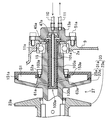
- FIG. 1 is a cross-sectional view showing a continuously variable transmission system according to an embodiment of the present invention including a cooling mechanism.
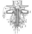
- FIG. 2 is an enlarged cross-sectional view showing the configuration of the first rotating shaft and the driving pulley.
- FIG. 3 is a cross-sectional view (center) along the axial direction of the cylindrical first fitting member, a cross-sectional view (left side) in a direction parallel to the bottom surface, and a top view (right side).
- FIG. 4 is an enlarged cross-sectional view showing the configurations of the second rotating shaft and the driven pulley.
- FIG. 5 is a cross-sectional view (center) along the axial direction of the cylindrical second fitting member, a cross-sectional view (left side) in a direction parallel to the bottom surface, and a top view (right side).
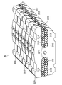
- FIG. 6 is a perspective view illustrating an example of a belt used in the continuously variable transmission according to the embodiment.
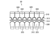
- FIG. 7 is a side view of the belt shown in FIG.
- FIG. 1 is a cross-sectional view showing a continuously variable transmission system according to an embodiment of the present invention including a cooling mechanism.
- FIG. 2 is an enlarged cross-sectional view showing the configuration of the first rotating shaft and the driving pulley.
- FIG. 3 is a cross-sectional view (center) along the axial direction of the cylindrical first fitting member, a cross-sectional view (left side) in a direction parallel to the bottom surface, and a top view (right side).
- FIG. 4 is an enlarged cross-sectional view showing the configuration of the second rotating shaft and the driven pulley
- FIG. 5 is a cross-sectional view (center) along the axial direction of the cylindrical second fitting member. It is sectional drawing (left side) in a parallel direction, and a top view (right side).
- continuously variable transmission and a continuously variable transmission system including the continuously variable transmission will be described as examples of belt transmission devices.
- the continuously variable transmission system 1 of the present embodiment is disposed in a power transmission path between a vehicle engine and drive wheels.
- the continuously variable transmission system 1 includes a continuously variable transmission 3, a case 9 that covers the main components of the continuously variable transmission 3, and cooling to the continuously variable transmission 3.
- a liquid cooling device 7 that supplies the liquid
- a pump (circulation means) 5 that circulates the cooling liquid between the liquid cooling device 7 and the continuously variable transmission 3, a liquid flow path 110 that constitutes a circulation path of the cooling liquid, 111, 112.
- the cooling liquid may be liquid and may be water or oil having a lubricating ability. Since water has a relatively high thermal conductivity, the cooling efficiency can be increased by using water as a coolant. On the other hand, since oil does not cause rust in the metal, the range of selection of members that form the flow path of the coolant can be widened by using the oil as the coolant.
- the continuously variable transmission 3 includes a first rotating shaft (input shaft) 15 and a second rotating shaft (output shaft) 17 arranged side by side, and a drive pulley 33 provided on the first rotating shaft 15. And a driven pulley 34 provided on the second rotating shaft 17, and a belt 30 that is wound between the driving pulley 33 and the driven pulley 34 and has substantially V-shaped sides.
- the driving pulley 33, the driven pulley 34 and the belt 30 are disposed in the case 9.
- FIG. 1 shows an example in which the first rotating shaft 15 and the second rotating shaft 17 are parallel to each other.
- a part of the front end side (left end side in FIG. 1) of the first rotating shaft 15 protrudes from the case 9 to the outside.
- the front end portion of the first rotary shaft 15 is rotatably supported by the bearing hole 4a of the case 9 via the bearing 14a, and the rear end portion of the first rotary shaft 15 is supported by the bearing hole 2a of the case 9.
- the bearing 11a is rotatably supported.
- a bottomed substantially cylindrical bracket 13 a fixed to the case 9 by a fixing member such as a bolt 51 a covers the rear end portion of the first rotating shaft 15. It is attached.
- a part of the rear end side (right end side in FIG. 1) of the second rotary shaft 17 protrudes from the case 9 to the outside in the same manner as the first rotary shaft 15.
- the front end portion of the second rotary shaft 17 is rotatably supported by the bearing hole 2b of the case 9 via the bearing 11b, and the rear end portion of the second rotary shaft 17 is supported by the bearing hole 4b of the case 9.
- a bearing 14b is rotatably supported.
- a bottomed substantially cylindrical bracket 13 b fixed to the case 9 by a fixing member such as a bolt 51 b is attached so as to cover the rear end portion of the first rotating shaft 15. It has been.
- the drive pulley 33 is fixedly supported on the first rotating shaft 15 and has a disk-shaped fixed sheave 31a having a hollow portion S1 formed therein, and a fixed sheave 31a. And a movable sheave 23a supported on the first rotary shaft 15 so as to be integrally rotated and movable in the axial direction so as to form a belt groove 27 therebetween.
- the belt groove 27 has a substantially V-shaped cross-sectional shape in which the groove width becomes narrower from the radially outer side to the inner side of the drive pulley 33.
- the inner surface of the belt groove 27 is in contact with both side surfaces of the belt 30.
- the fixed sheave 31a may be a flange-like member that is coupled to the first rotating shaft 15 so as to rotate integrally and not to slide. 1 and 2, the fixed sheave 31a includes a circular fixed sheave half 22a formed integrally with the first rotating shaft 15, and a movable sheave 23a so as to form a hollow portion S1. May have a back plate 25a attached to the fixed sheave half 22a from the reverse side (back side).
- the back plate 25a has an opening for passing the first rotary shaft 15 in the center, and is fixed by a bolt 52a in a state of being fitted into the first rotary shaft 15. At least the rear end side of the first rotating shaft 15 is tubular.
- the hollow portion S1 is a donut-shaped space surrounding the shaft portion of the first rotating shaft 15 inside the fixed sheave 31a. During the operation of the continuously variable transmission 3, the hollow portion S1 is filled with the coolant. Rings 151a and 153a for preventing leakage of the coolant are provided at the joint portion between the fixed sheave half 22a and the back plate 25a.
- An inflow communication path 61a and an outflow communication path that extend inward in the radial direction from the hollow portion S1 and open to the inner wall of the first rotation shaft 15 are formed in the portion of the first rotation shaft 15 where the fixed sheave 31a is formed.
- 63a is formed.
- the number and formation positions of the inflow communication path 61a and the outflow communication path 63a are not particularly limited, but the inflow communication path 61a and the outflow communication path 63a are to some extent in order to effectively circulate a coolant described later in the hollow portion S1. It may be formed at a distant position.
- the formation position of one of the inflow communication path 61 a and the outflow communication path 63 a may be provided at a position shifted by 180 ° with respect to the axis of the first rotating shaft 15.
- a first fitting member 100a having a substantially cylindrical shape with a bottom, for example, is fitted to the first rotating shaft 15 from the rear end side. In the insertion state, the inner wall of the first rotating shaft 15 and the side surface of the first insertion member 100a are in close contact.
- the first fitting member 100a only needs to have a shape that is closely fitted into the space inside the first rotating shaft 15, and may be, for example, substantially cylindrical as shown in FIG.
- the first insertion member 100a has a solid structure made of a metal such as aluminum or a resin, and a cooling liquid inflow passage 101a and an outflow passage 103a are formed therein.
- the inflow path 101a and the outflow path 103a can be formed using a tool such as a drill.
- a tool such as a drill.
- the constituent material of the 1st insertion member 100a is not specifically limited, Since it will be easy to process if it is comprised with the metal etc. whose hardness is lower than the 1st rotating shaft 15, resin is preferable.
- the inflow path 101a communicates with the hollow portion S1 through the inflow communication path 61a. Further, the outflow path 103a communicates with the hollow portion S1 through the outflow communication path 63a.
- the position, number, and size of the inflow path 101a and the outflow path 103a are not particularly limited, but the inflow path 101a is directly connected to the inflow communication path 61a, and the outflow path 103a is directly connected to the outflow communication path 63a. , Each designed.
- the inflow path 101 a includes a first portion extending in a direction parallel to the axial direction of the first rotation shaft 15 at the center portion of the first insertion member 100 a, and a bottom side of the first portion. A second portion extending from the end portion toward the radially outer side and connected to the inflow communication path 61a.
- the outflow path 103a has a first portion extending in the first insertion member 100a in a direction parallel to the axial direction of the first rotation shaft 15, and a radially outer side from the bottom side end of the first portion. And a second portion connected to the outflow communication path 63a.
- the inflow path 101a, the inflow communication path 61a, the hollow portion S1, the outflow communication path 63a, and the outflow path 103a constitute a coolant circulation path.
- the first fitting member 100a has a convex portion 105a provided along the circumferential direction on the upper end side (the rear end side in the continuously variable transmission 3; the right side in FIG. 1).
- the distance from the lower end of the convex portion 105a to the opening portion of the inflow passage 101a on the side surface of the first fitting member 100a is the axial center side opening portion of the inflow communication passage 61a from the rear end portion of the first rotation shaft 15 (first 1 to the insertion member 100a side opening).
- the distance from the lower end of the convex portion 105a to the opening of the outflow passage 103a on the side surface of the first fitting member 100a is the opening on the axial center side of the outflow communication passage 63a from the rear end of the first rotating shaft 15. It is equal to the distance.
- the inflow passage 101a and the inflow communication are established by inserting the first insertion member 100a into the first rotation shaft 15 to a depth where the convex portion 105a and the rear end portion of the first rotation shaft 15 come into contact with each other.
- the alignment with the channel 61a and the alignment between the outflow channel 103a and the outflow communication channel 63a can be easily performed.
- a groove extending in the circumferential direction is formed in a portion of the side surface portion of the first insertion member 100a where the inflow passage 101a extending outward in the radial direction is opened.
- the groove extending in the circumferential direction is also formed in a portion of the side surface portion of the first fitting member 100a where the outflow passage 103a is opened.
- the upper end portion of the first insertion member 100a is pressed by the bracket 13a, and the first insertion member 100a is fixed so as not to come off from the first rotating shaft 15.
- a liquid channel 110 penetrating the bracket 13a is connected to the inflow channel 101a.
- a liquid channel 111 penetrating the bracket 13a is connected to the outflow channel 103a.
- a groove 109a extending in the circumferential direction is formed on the bottom side of the first insertion member 100a so as to sandwich the opening of the inflow passage 101a and the opening of the outflow passage 103a from above and below, and rubber or the like is formed in the groove 109a.
- the oil seal 130a which consists of is inserted.
- a ring-shaped oil seal 47a is provided between the inflow path 101a and the bracket 13a, and a ring-shaped oil seal 45a is also provided between the outflow path 103a and the bracket 13a.
- the coolant that has flowed into the continuously variable transmission 3 from the liquid channel 110 is supplied to the hollow portion S1 through the inflow channel 101a and the inflow communication channel 61a, and the fixed sheave 31a can be cooled from the inside. .
- the cooling liquid that has cooled the fixed sheave 31a flows out from the hollow portion S1 to the liquid flow path 111 through the outflow communication path 63a and the outflow path 103a.
- the fixed sheave 31a can be effectively cooled by the coolant. Further, the belt 30 can be effectively cooled via the fixed sheave 31a.
- the driven pulley 34 provided on the second rotating shaft 17 and its cooling mechanism may be substantially the same as the driving pulley 33 and its cooling mechanism.
- the driven pulley 34 and the second insertion member 100 b have substantially the same configuration except that the drive pulley 33 and the first insertion member 100 a are arranged in the left-right direction.
- the configuration on the driven pulley 34 side will be specifically described.
- the driven pulley 34 is fixedly supported on the second rotating shaft 17 and is formed so that a belt groove 29 is formed between the fixed sheave 31b having a disk shape with a hollow portion S2 formed therein and the fixed sheave 31b.
- the movable sheave 23b is supported on the second rotary shaft 17 so as to be integrally rotated and movable in the axial direction.
- the belt groove 29 has a substantially V-shaped cross-sectional shape in which the groove width becomes narrower from the radially outer side to the inner side of the driven pulley 34.
- the inner surface of the belt groove 29 is in contact with both side surfaces of the belt 30.
- the fixed sheave 31b may be a flange-like member that is coupled to the second rotating shaft 17 so as to rotate integrally and not to slide. 1 and 4, the fixed sheave 31b includes a circular fixed sheave half 22b formed integrally with the second rotary shaft 17, and a movable sheave 23b so as to form a hollow portion S2. May have a back plate 25b attached to the fixed sheave half 22b from the reverse side (back side).
- the back plate 25b has an opening for allowing the second rotary shaft 17 to pass through in the center, and is fixed by a bolt 52b while being fitted into the second rotary shaft 17. At least the rear end side of the second rotating shaft 17 is tubular.
- the hollow portion S2 is a donut-shaped space that surrounds the shaft portion of the second rotating shaft 17 inside the fixed sheave 31b. During the operation of the continuously variable transmission 3, the hollow portion S2 is filled with the coolant. Rings 151b and 153b made of rubber or the like and for preventing leakage of the coolant are provided at the joint portion between the fixed sheave half 22b and the back plate 25b.
- the number and formation positions of the inflow communication path 61b and the outflow communication path 63b are not particularly limited, but the inflow communication path 61b and the outflow communication path 63b are to some extent in order to effectively circulate a coolant described later in the hollow portion S2. It may be formed at a distant position.
- a bottom-inserted substantially cylindrical second fitting member 100b is fitted into the second rotating shaft 17 from the front end side. In the fitted state, the inner wall of the second rotating shaft 17 and the side surface of the second fitting member 100b are in close contact.
- the second fitting member 100b only needs to have a shape that is closely fitted in the space inside the second rotating shaft 17, and may be, for example, substantially cylindrical as shown in FIG.
- the second fitting member 100b has a solid structure made of a metal such as aluminum or a resin, and a cooling liquid inflow passage 101b and an outflow passage 103b are formed therein.
- the inflow path 101b and the outflow path 103b can be formed using a tool such as a drill.
- a tool such as a drill.
- the constituent material of the 2nd insertion member 100b is not specifically limited, Since it will be easy to process if it is comprised with the metal etc. whose hardness is lower than the 2nd rotating shaft 17, it is preferable.
- the first insertion member 100a and the second insertion member are preferable in terms of manufacturing cost as long as the whole is made of a uniform and single component material, but is not limited thereto.
- Each of the first insertion member 100a and the second insertion member 100b may be composed of a plurality of parts.
- the 1st insertion member 100a may be comprised by two parts cut
- the 1st rotating shaft 15 and the 2nd rotating shaft 17 are comprised, for example with metals, such as carbon steel.
- the inflow path 101b communicates with the hollow portion S2 through the inflow communication path 61b. Further, the outflow path 103b communicates with the hollow portion S2 through the outflow communication path 63b.
- the position and number of the inflow path 101b and the outflow path 103b are not particularly limited, but the inflow path 101b is designed to be directly connected to the inflow communication path 61b, and the outflow path 103b is designed to be directly connected to the outflow communication path 63a. Is done.
- the inflow path 101 b includes a first portion extending in a direction parallel to the axial direction of the second rotation shaft 17 at the center portion of the second fitting member 100 b, and a bottom side of the first portion.
- a second portion extending from the end portion toward the radially outer side and connected to the inflow communication path 61b.
- the outflow path 103b is a first portion extending in a direction parallel to the axial direction of the second rotating shaft 17 in the second fitting member 100b, and radially outward from the bottom side end of the first portion.
- a second portion connected to the outflow communication path 63b.
- the inflow path 101b, the inflow communication path 61b, the hollow portion S2, the outflow communication path 63b, and the outflow path 103b constitute a coolant circulation path.
- the second fitting member 100b has a convex portion 105b provided along the circumferential direction on the upper end side (front end side in the continuously variable transmission 3; left side in FIG. 1).
- the distance from the lower end of the convex portion 105b to the opening of the inflow passage 101b on the side surface of the second fitting member 100b is the opening on the axial center side of the inflow communication passage 61b from the front end of the second rotating shaft 17 (second To the fitting member 100b side opening).
- the distance from the lower end of the convex portion 105b to the opening of the outflow passage 103b on the side surface of the second fitting member 100b is the opening on the axial center side of the outflow communication passage 63b from the rear end of the second rotating shaft 17. It is equal to the distance.
- the inflow path 101b and the inflow communication path are inserted by inserting the second insertion member 100b into the second rotation shaft 17 to a depth at which the convex portion 105b and the front end of the second rotation shaft 17 abut.
- the alignment with 61b and the alignment between the outflow passage 103b and the outflow communication passage 63b can be easily performed.
- a groove extending in the circumferential direction is formed in a portion of the side surface portion of the second insertion member 100b where the inflow passage 101b extending outward in the radial direction is opened.
- the groove extending in the circumferential direction is also formed in a portion of the side surface portion of the second fitting member 100b where the outflow passage 103b is opened.
- the upper end portion of the second insertion member 100b is pressed by the bracket 13b, and the second insertion member 100b is fixed so as not to come off the second rotating shaft 17.
- a liquid channel 111 penetrating the bracket 13b is connected to the inflow channel 101b.
- the outflow path 103b is connected to a liquid flow path 112 that penetrates the bracket 13b.
- a groove 109b extending in the circumferential direction is formed on the bottom side of the second fitting member 100b so as to sandwich the opening of the inflow passage 101b and the opening of the outflow passage 103b from above and below, and rubber or the like is formed in the groove 109b.
- the oil seal 130b which consists of is inserted.
- a ring-shaped oil seal 47b is provided between the inflow path 101b and the bracket 13b, and a ring-shaped oil seal 45b is also provided between the outflow path 103b and the bracket 13b.
- the coolant that has flowed into the continuously variable transmission 3 from the liquid flow path 111 is supplied to the hollow portion S2 through the inflow path 101b and the inflow communication path 61b, and the fixed sheave 31b can be cooled from the inside. .
- the cooling liquid that has cooled the fixed sheave 31b flows out from the hollow portion S2 to the liquid flow path 112 through the outflow communication path 63b and the outflow path 103b.
- the belt 30 can be effectively cooled by the coolant via the stationary sheave 31b even on the driven pulley 34 side.
- the belt 30 used in the continuously variable transmission 3 of the present embodiment has a so-called substantially V shape on both sides, and may be a transmission belt that can withstand a relatively high load.
- An exemplary configuration of the belt 30 will be described.
- FIG. 6 is a perspective view showing an example of a belt used in the continuously variable transmission according to the embodiment
- FIG. 7 is a side view of the belt shown in FIG.
- the belt 30 may be a belt of a type in which lubricating oil is interposed between both side surfaces and the belt grooves 27 and 29, or may be a CVT (Continuously Variable Transmission) belt that does not require the use of lubricating oil.
- CVT Continuous Variable Transmission
- the belt 30 may be made of metal, lubricating oil is required.
- the belt 30 is made of resin and has a side surface made of resin, the metal and the resin come into contact with each other at the contact portion with the pulley (belt grooves 27 and 29). Lubricating oil is unnecessary. When the belt 30 described below is used, lubricating oil is not necessarily required.
- the belt 30 includes a pair of endless tension bands 310 and a plurality of blocks 320.
- the pair of tension bands 310 are provided so as to extend in parallel in the belt length direction, and the plurality of blocks 320 include a pair of the tension bands 310.
- the tension band 310 is arranged at a constant pitch and spaced from each other, and each block 320 is locked to the pair of tension bands 310.
- the tension band 310 is fitted in fitting portions 321 formed on both sides of each block 320.
- the tension band 310 includes a shape retaining rubber layer 313 and a core wire 314 embedded in the shape retaining rubber layer 313 so as to form a spiral having a pitch in the belt width direction.
- the block 320 is made of metal or resin.
- the upper side surface 322 and the lower side surface 323 of the block 320 and the side surface 330 of the tension band are contact surfaces with the belt groove 27.
- the belts in the driving pulley 33 and the driven pulley 34 correspond to changes in the groove widths of the belt grooves 27 and 29 by sliding both side surfaces of the belt 30 on the inner surface of the groove. It becomes possible to change the winding diameter of 30 continuously.
- a tension mechanism 40 that provides The tension mechanism 40 has a tension arm 41 that is rotatably supported.
- a tension shaft 42 extending rearward is provided at the distal end of the tension arm 41 in parallel with the first rotation shaft 15, and the slack side span of the belt 30 can be pressed from the inner surface to the distal end of the tension shaft 42.
- a tension pulley 43 is rotatably supported via a bearing 44.
- a drive pulley side cam mechanism 50 a which is a drive mechanism for bringing the movable sheave 23 a into and out of contact with the fixed sheave 31 a on the back side of the movable sheave 23 a in the drive pulley 33.
- this drive pulley side cam mechanism 50a a well-known drive mechanism can be used, for example, you may have the cylindrical rotation cam 60a.
- the rotating cam may be externally fitted and supported integrally with the cylindrical portion of the movable sheave 23a through the bearing 12a so as to be relatively rotatable around the first rotating shaft 15 and moving in the axial direction.
- a driven pulley side cam mechanism 50 b is provided on the back side of the movable sheave 23 b in the driven pulley 34 as a drive mechanism for moving the movable sheave 23 b to and from the fixed sheave 31 b. It has been.
- the driven pulley side cam mechanism 50b may have the same configuration as the drive pulley side cam mechanism 50a.
- the driven pulley side cam mechanism 50b has a cylindrical rotating cam 60b, and the rotating cam 60b can rotate relative to the second rotating shaft 17 around the cylindrical portion of the movable sheave 23b via the bearing 12b. Further, the outer fitting support may be carried out integrally in the axial direction.
- a shaft insertion hole (not shown) is formed in the front wall portion of the case 9 at a position on a plane between the first rotating shaft 15 and the second rotating shaft 17 and passing through the axial centers of the rotating shafts 15 and 17.
- the operation shaft 73 extending in a direction parallel to the first rotation shaft 15 and the second rotation shaft 17 is rotatably supported by the bearing 74 in the shaft insertion hole.
- One end of the operation shaft 73 extends to the outside of the case 9, and an operation lever (not shown) is attached to the end of the operation shaft 73 so as to rotate together.
- the other end of the operation shaft 73 is connected to the rotation lever 54a side of the link bar via a crank arm 75 and a connecting rod (not shown) made of a plate curved in a substantially “ ⁇ ” shape.
- the shift switching mechanism is operated from the outside of the case 9 so as to project from the rotating cams 60a and 60b.
- the rotating levers 54a and 54b can be rotated.
- the pulley ratio of the speed change pulley mechanism constituted by the drive pulley 33 and the driven pulley 34 is changed, and the second rotary shaft 17 is steplessly set to the deceleration state or the acceleration state with respect to the first rotation shaft 15. Switching speed can be changed.
- the rotational power of the engine is the continuously variable transmission 3. After being shifted, it is transmitted to the drive wheels. Since the rotation levers 54a and 54b in the drive pulley side rotation cam mechanism 50a and the driven pulley side rotation cam mechanism 50b are linked by the link bar 71, the pulley of the speed change pulley mechanism is operated by the switching operation of the operation shaft 73. The gear ratio of the continuously variable transmission 3 is switched by changing the ratio.
- the movable sheave 23a of the drive pulley 33 is moved in the direction in which the belt groove 27 is expanded by the drive pulley side cam mechanism 50a, and the position of the belt 30 is moved to the position A shown in FIG. Further, the movable sheave 23b of the driven pulley 34 is moved in the direction in which the belt groove 29 is narrowed by the driven pulley side rotating cam mechanism 50b, and the position of the belt 30 is moved to the position C.
- the movable sheave 23a of the drive pulley 33 is moved in the direction in which the belt groove 27 is narrowed by the drive pulley side cam mechanism 50a, and the position of the belt 30 is moved to the position B shown in FIG. Further, the movable sheave 23b of the driven pulley 34 is moved in the direction in which the belt groove 29 expands by the driven pulley side rotating cam mechanism 50b, and the position of the belt 30 is moved to the position D.
- the hollow portion S1 is provided in the fixed sheave 31a, and the first insertion member 100a in which the cooling liquid inflow path 101a and the outflow path 103a are formed is fitted. Yes.
- the first rotary shaft 15 and the first fitting member 100a can be made of different materials.
- the rotary shaft since a large load is applied to the rotary shaft of the continuously variable transmission, the rotary shaft is formed of a material having high hardness.
- a tool such as a drill, machining is difficult and the tool may be damaged or the rotating shaft may be damaged.
- the first insertion member 100a can be made of a metal having a hardness lower than that of the rotating shaft, so that the inflow path 101a and the outflow path 103a can be easily and reliably formed.
- the constituent material of the first fitting member 100a is made of aluminum, phenol resin, or the like having a relatively low hardness, the processing when forming the inflow passage 101a and the outflow passage 103a can be facilitated.
- the 1st insertion member 100a is preferable in terms of manufacturing cost if the whole is comprised with the homogeneous and single component material, as above-mentioned, it is not restricted to this.
- the first insertion member 100a can be manufactured by a process different from the processing of the first rotating shaft 15, the first insertion member 100a is prepared in advance, so that the continuously variable transmission 3 It is also possible to shorten the time required for assembly.
- the lengths of the inflow communication path 61a and the outflow communication path 63a are as follows. Since it is very short compared with the inflow path 101a and the outflow path 103a, the process for forming the inflow communication path 61a and the outflow communication path 63a is easy.
- the first insertion member 100a for example, compared to a case where a hollow portion is provided in the first rotating shaft 15, and a thin tube serving as an inflow passage and an outflow passage is separately provided in the hollow portion, the inflow passage.
- the first fitting member 100a is fitted into the first rotating shaft 15, after the inflow passage 101a and the outflow passage 103a are aligned and fixed so as to be connected to the hollow portion S1, the first insertion member 100a is subjected to severe vibration.
- the displacement of the inflow path 101a and the outflow path 103a is less likely to occur. For this reason, it is difficult for the coolant to leak out.
- the leakage of the coolant can be prevented by using the oil seals 45a, 47a, 130a and the like.
- both the inflow path 101a and the outflow path 103a for circulating the coolant through the hollow portion S1 in the fixed sheave 31a are disposed in the first rotating shaft 15, It is possible to prevent the coolant from staying in the part S1, and to cool the fixed sheave 31a and the belt 30 efficiently.
- a cooling mechanism including a hollow portion S1 is provided in the fixed sheave 31a.
- the fixed sheave half 22a of the fixed sheave 31a is formed integrally with the first rotating shaft 15, more heat is transmitted from the engine to the fixed sheave 31a than to the movable sheave 23a. For this reason, it becomes possible to cool the belt 30 effectively by providing a cooling mechanism on the fixed sheave 31a side.
- the cooling mechanism is provided on the fixed sheave 31a side, so that the leakage of the coolant is less likely to occur compared to the case where the cooling mechanism is provided on the movable sheave 23a side with large movement. As a result, the number of parts of the continuously variable transmission 3 can be reduced.
- the outflow communication path 63a By forming the outflow communication path 63a, the number of parts constituting the cooling mechanism can be minimized.
- the first fitting member 100a is provided with alignment means such as the convex portion 105a, it is easy to align the inflow path 101a and the inflow communication path 61a and align the outflow path 103a and the outflow communication path 63a. And since it can implement with a sufficient precision, the leakage of a cooling fluid can be prevented effectively.
- a cooling mechanism similar to that on the drive pulley 33 side is also provided on the driven pulley 34 side. That is, after the hollow portion S2 is provided in the fixed sheave 31b constituting the driven pulley 34, the second fitting member 100b in which the inflow path 101b and the outflow path 103b are formed is disposed in the second rotating shaft 17. It is inserted. For this reason, the same effect as the cooling mechanism on the drive pulley 33 side can be obtained also on the driven pulley 34 side.
- the coolant in the hollow portion S2 is less likely to stay, and the fixed sheave 31b and the belt 30 can be effectively cooled. Also, by preparing the second fitting member 100b in advance, not only can the tool and the second rotating shaft 17 be prevented from being damaged, but also the time required for assembling the continuously variable transmission 3 can be shortened.
- the belt 30 can be effectively cooled on both the drive pulley 33 side and the driven pulley 34 side, and processing and assembly are facilitated. be able to.
- the cooling mechanism including the fitting member is provided on at least one of the driving pulley 33 side and the driven pulley 34 side, the cooling effect of the belt 30 can be obtained.
- it is possible to effectively prevent the belt 30 from being overheated by providing the cooling mechanism of the present embodiment on the side of the drive pulley 33 where heat from the engine is easily transmitted.
- another pulley may be appropriately disposed between the drive pulley 33 and the driven pulley 34.
- the belt transmission device described in this specification can be used as a belt-type transmission of a vehicle such as an automobile, an agricultural machine, or a general-purpose machine.
Landscapes
- Engineering & Computer Science (AREA)
- General Engineering & Computer Science (AREA)
- Mechanical Engineering (AREA)
- Transmissions By Endless Flexible Members (AREA)
- General Details Of Gearings (AREA)
Abstract
ベルト伝動装置3は、駆動プーリ33及び従動プーリ34と、ベルト30とを備える。駆動プーリ33及び従動プーリ34は、内部に中空部S1、S2が形成された固定シーブ31a、31bと、可動シーブ23a、23bとを有し、プーリが設けられた回転軸15、17内には、中空部S1、S2にそれぞれ連通する流入路101a、101b及び流出路103a、103bが内部に形成された嵌入部材100a、100bが嵌入される。
Description
本発明は、ベルトを介して動力を伝達するベルト伝動装置に関するものである。
ベルトを介して動力を伝達するベルト伝動装置は、例えば車両等の無段変速機等として広く用いられている。このようなベルト伝動装置では、プーリと、プーリに巻き掛けられたベルトとの間の摩擦熱や、動力源から伝わる熱等によりプーリやベルトが高温になるので、プーリ及びベルトを冷却するための構造が種々検討されている。
特許文献1、2には、プーリ内に中空部を設けるとともに、プーリの回転軸内に上記中空部に連通する流路を設け、プーリ内の中空部に冷却流体を供給することで、プーリ及びベルトの冷却を図る技術が記載されている。
上記特許文献1に記載された技術では、キリ等の工具を用いて回転軸であるシャフト本体に冷却流体用の細長い穴(上記の流路)を開ける加工が必要となる。しかし、シャフト本体は、高い負荷に耐えられるように、一般的に剛性の高い材料により構成されることが多いので、穴を形成する加工には時間を要する場合がある。
また、特許文献2に記載された技術では、回転軸内に冷却流体の流入路のみが設けられており、プーリ内の中空部に連通する流出路は回転軸外に別途設けられる。この構成によれば、プーリ内での冷却流体の滞留時間が長くなり、冷却効率が低下しやすくなる。
本発明は、かかる点に鑑みてなされたものであり、ベルト等を効果的に冷却するとともに、加工が容易なベルト伝動装置を提供することにある。
本発明の実施形態に係るベルト伝動装置の一例は、第1の回転軸上に設けられた駆動プーリと、前記第1の回転軸と並んで配置された第2の回転軸上に設けられた従動プーリと、前記駆動プーリと従動プーリとの間に巻き掛けられたベルトとを備えたベルト伝動装置である。前記駆動プーリ及び前記従動プーリの少なくとも一方は、前記第1の回転軸又は前記第2の回転軸上に固定支持され、内部に中空部が形成された円盤状の固定シーブと、前記固定シーブとの間にベルト溝を形成するように前記第1の回転軸又は前記第2の回転軸上に回転一体且つ軸線方向に移動可能に支持された可動シーブとを有し、前記第1の回転軸及び前記第2の回転軸のうち、前記固定シーブが設けられた回転軸は管状であり、前記回転軸内に嵌入され、前記中空部にそれぞれ連通する流入路及び流出路が内部に形成された有底の嵌入部材をさらに備えており、前記流入路及び流出路は、前記中空部内に供給される冷却液の循環経路を構成する。
本明細書に開示されたベルト伝動装置によれば、ベルトを効果的に冷却することができるとともに、製造時の加工が容易になっている。
以下、本発明の実施形態を図面に基づいて説明する。なお、以下の好ましい実施形態の説明は、本質的に例示に過ぎず、本発明、その適用物或いはその用途を制限することを意図するものではない。
-ベルト伝動装置の全体構成及び冷却機構-
図1は、冷却機構を含めた本発明の実施形態に係る無段変速システムを示す断面図である。図2は、第1の回転軸及び駆動プーリの構成を拡大して示す断面図である。図3は、円筒状の第1の嵌入部材の軸線方向に沿った断面図(中央)、底面に平行な方向における断面図(左側)、及び上面図(右側)である。図4は、第2の回転軸及び従動プーリの構成を拡大して示す断面図であり、図5は、円筒状の第2の嵌入部材の軸線方向に沿った断面図(中央)、底面に平行な方向における断面図(左側)、及び上面図(右側)である。
図1は、冷却機構を含めた本発明の実施形態に係る無段変速システムを示す断面図である。図2は、第1の回転軸及び駆動プーリの構成を拡大して示す断面図である。図3は、円筒状の第1の嵌入部材の軸線方向に沿った断面図(中央)、底面に平行な方向における断面図(左側)、及び上面図(右側)である。図4は、第2の回転軸及び従動プーリの構成を拡大して示す断面図であり、図5は、円筒状の第2の嵌入部材の軸線方向に沿った断面図(中央)、底面に平行な方向における断面図(左側)、及び上面図(右側)である。
以下では、ベルト伝動装置の例として無段変速機と、これを備えた無段変速システムについて説明する。図示しないが、本実施形態の無段変速システム1は、車両のエンジンと駆動車輪との間の動力伝達経路に配設されている。
図1~図5に示すように、本実施形態の無段変速システム1は、無段変速機3と、無段変速機3の主要構成部を覆うケース9と、無段変速機3に冷却液を供給する液体冷却装置7と、液体冷却装置7と無段変速機3との間で冷却液を循環させるポンプ(流通手段)5と、冷却液の循環経路を構成する液体流路110、111、112とを備えている。冷却液は液体であればよく、水であってもよいし、潤滑能力を有する油であってもよい。水は比較的熱伝導率が高いので、水を冷却液として用いることで、冷却効率を上げることができる。一方、油は金属に錆を生じさせないので、油を冷却液として用いることで、冷却液の流通経路を形成する部材の選択の幅を広げることができる。
無段変速機3は、互いに並んで配置された第1の回転軸(入力軸)15及び第2の回転軸(出力軸)17と、第1の回転軸15上に設けられた駆動プーリ33と、第2の回転軸17上に設けられた従動プーリ34と、駆動プーリ33と従動プーリ34との間に巻き掛けられ、両側面が略V字状のベルト30とを備えている。駆動プーリ33、従動プーリ34及びベルト30は、ケース9内に配設されている。図1は、第1の回転軸15と第2の回転軸17とが互いに平行になっている例を示している。
第1の回転軸15の前端側(図1の左端側)の一部は、ケース9から外部へと突出している。第1の回転軸15の前端部は、ケース9の軸受孔4aにベアリング14aを介して回転可能に支持されており、第1の回転軸15の後端部は、ケース9の軸受孔2aにベアリング11aを介して回転可能に支持されている。第1の回転軸15の後端側には、ボルト51a等の固定部材によってケース9に固定された有底略円筒状のブラケット13aが、第1の回転軸15の後端部を覆うように取り付けられている。
第2の回転軸17の後端側(図1の右端側)の一部は、第1の回転軸15と同様にケース9から外部へと突出している。第2の回転軸17の前端部は、ケース9の軸受孔2bにベアリング11bを介して回転可能に支持されており、第2の回転軸17の後端部は、ケース9の軸受孔4bにベアリング14bを介して回転可能に支持されている。第2の回転軸17の前端側には、ボルト51b等の固定部材によってケース9に固定された有底略円筒状のブラケット13bが、第1の回転軸15の後端部を覆うように取り付けられている。
本実施形態に係る無段変速機3において、駆動プーリ33は、第1の回転軸15上に固定支持され、内部に中空部S1が形成された円盤状の固定シーブ31aと、固定シーブ31aとの間にベルト溝27を形成するように第1の回転軸15上に回転一体且つ軸線方向に移動可能に支持された可動シーブ23aとを有している。ベルト溝27は駆動プーリ33の径方向の外側から内側に向かうにつれて溝幅が狭くなる略V字状の断面形状を有している。ベルト溝27の内側面は、ベルト30の両側面と接触する。
固定シーブ31aは、第1の回転軸15上に回転一体且つ摺動不能に結合されたフランジ状の部材であってもよい。また、固定シーブ31aは、図1、2に示すように、第1の回転軸15と一体的に形成された円形の固定シーブ半体22aと、中空部S1を形成するように可動シーブ23aとは逆側(背面側)から固定シーブ半体22aに取り付けられた背面板25aとを有していてもよい。
固定シーブ半体22aが第1の回転軸15と一体的に形成される場合、固定シーブ半体22aを第1の回転軸15と別の部品とする場合に比べて無段変速機3の部品点数を減らすことができる。この背面板25aは、中央に第1の回転軸15を通すための開口部を有しており、第1の回転軸15に嵌め込まれた状態でボルト52aによって固定される。第1の回転軸15の少なくとも後端側は管状になっている。
中空部S1は、固定シーブ31aの内部において第1の回転軸15の軸部分を囲むドーナツ状の空間である。無段変速機3の動作時には中空部S1に冷却液が満たされる。固定シーブ半体22aと背面板25aとの接合部分には、冷却液の漏れを防ぐためのリング151a、153aが設けられている。
第1の回転軸15のうち固定シーブ31aが形成された部分には、それぞれ中空部S1から径方向内側へと延び、第1の回転軸15の内壁に開口する流入連絡路61a及び流出連絡路63aとが形成されている。流入連絡路61a及び流出連絡路63aの本数及び形成位置は特に限定されないが、中空部S1内に後述する冷却液を効果的に循環させるため、流入連絡路61aと流出連絡路63aとは、ある程度離れた位置に形成されてもよい。例えば、流入連絡路61aと流出連絡路63aのうちの一本との形成位置は第1の回転軸15の軸線を基準として180°ずれた位置に設けられていてもよい。
また、第1の回転軸15には、後端側から、例えば有底略円筒状の第1の嵌入部材100aが嵌め込まれている。嵌入状態において、第1の回転軸15の内壁と第1の嵌入部材100aの側面とは密接している。
第1の嵌入部材100aは、第1の回転軸15内部の空間に密接嵌入される形状を有していればよく、図3に示すように、例えば略円筒状であってもよい。第1の嵌入部材100aはアルミニウム等の金属や、樹脂からなる中実構造を有しており、その内部には冷却液の流入路101a及び流出路103aが形成されている。
流入路101a及び流出路103aは、例えばキリ等の工具を用いて形成することができる。第1の嵌入部材100aの構成材料は特に限定されないが、第1の回転軸15よりも硬度の低い金属等や樹脂で構成されていれば、加工が容易になるので好ましい。
流入路101aは、流入連絡路61aを介して中空部S1に連通する。また、流出路103aは、流出連絡路63aを介して中空部S1に連通する。
流入路101a及び流出路103aの位置、本数及び大きさは、特に限定されないが、流入路101aは流入連絡路61aと直接接続するように、流出路103aは流出連絡路63aと直接接続するように、それぞれ設計される。
図3に示す例では、流入路101aは、第1の嵌入部材100aの中心部において第1の回転軸15の軸線方向に平行な方向に延びる第1の部分と、第1の部分の底部側端部から径方向外側に向かって延び、流入連絡路61aに接続する第2の部分とを有している。流出路103aは、第1の嵌入部材100a内を第1の回転軸15の軸線方向に平行な方向に延びる第1の部分と、第1の部分の底部側端部から径方向外側に向かって延び、流出連絡路63aに接続する第2の部分とを有している。
流入路101a(の第2の部分)、及び流出路103a(の第2の部分)は、第1の嵌入部材100aの側面に開口する。
本実施形態の無段変速機3において、流入路101a、流入連絡路61a、中空部S1、流出連絡路63a、流出路103aは、冷却液の循環経路を構成している。
第1の嵌入部材100aは、上端側(無段変速機3における後端側;図1における右側)に、周方向に沿って設けられた凸状部105aを有している。凸状部105aの下端から第1の嵌入部材100aの側面における流入路101aの開口部までの距離は、第1の回転軸15の後端部から流入連絡路61aの軸中心側開口部(第1の嵌入部材100a側開口部)までの距離と等しくなっている。また、凸状部105aの下端から第1の嵌入部材100aの側面における流出路103aの開口部までの距離は、第1の回転軸15の後端部から流出連絡路63aの軸中心側開口部までの距離と等しくなっている。
このため、凸状部105aと第1の回転軸15の後端部とが当接する深さまで第1の嵌入部材100aを第1の回転軸15内に嵌入することにより、流入路101aと流入連絡路61aとの位置合わせ、及び流出路103aと流出連絡路63aとの位置合わせを容易に行うことができる。
また、第1の嵌入部材100aの側面部のうち、径方向外側に向かって延びる流入路101aが開口する部分には、円周方向に延びる溝が形成されている。円周方向に延びる溝は、第1の嵌入部材100aの側面部のうち、流出路103aが開口する部分にも形成されている。これらの溝が形成されていることにより、周方向の位置合わせをしなくても、流入路101aと流入連絡路61aとの接続、及び流出路103aと流出連絡路63aとの接続をそれぞれ確保することが可能となる。
第1の嵌入部材100aの上端部はブラケット13aにより押さえつけられており、第1の嵌入部材100aは第1の回転軸15から抜けないように固定されている。流入路101aには、ブラケット13aを貫通する液体流路110が接続されている。流出路103aには、ブラケット13aを貫通する液体流路111が接続されている。
第1の嵌入部材100aの底部側には、流入路101aの開口部及び流出路103aの開口部を上下から挟むように、周方向に延びる溝109aが形成されており、この溝109aにゴム等からなるオイルシール130aが嵌め込まれている。また、流入路101aとブラケット13aとの間には、リング状のオイルシール47aが設けられ、流出路103aとブラケット13aとの間にもリング状のオイルシール45aが設けられている。
以上の構成により、液体流路110から無段変速機3内に流入した冷却液は、流入路101a及び流入連絡路61aを通って中空部S1へと供給され、固定シーブ31aを内部から冷却できる。固定シーブ31aを冷却した冷却液は、中空部S1から流出連絡路63a及び流出路103aを通って液体流路111へと流出する。
このため、後述するように、本実施形態の無段変速機3では、冷却液により固定シーブ31aを効果的に冷却することができる。また、固定シーブ31aを介してベルト30を効果的に冷却することもできる。
本実施形態の無段変速機3において、第2の回転軸17上に設けられた従動プーリ34及びその冷却機構は、駆動プーリ33及びその冷却機構とほぼ同様であってもよい。図1に示す例では、従動プーリ34及び第2の嵌入部材100bは、駆動プーリ33及び第1の嵌入部材100aを左右逆に配置した以外、ほぼ同様の構成を有している。以下、従動プーリ34側の構成を具体的に説明する。
従動プーリ34は、第2の回転軸17上に固定支持され、内部に中空部S2が形成された円盤状の固定シーブ31bと、固定シーブ31bとの間にベルト溝29を形成するように第2の回転軸17上に回転一体且つ軸線方向に移動可能に支持された可動シーブ23bとを有している。ベルト溝29は従動プーリ34の径方向の外側から内側に向かうにつれて溝幅が狭くなる略V字状の断面形状を有している。ベルト溝29の内側面は、ベルト30の両側面と接触する。
固定シーブ31bは、第2の回転軸17上に回転一体且つ摺動不能に結合されたフランジ状の部材であってもよい。また、固定シーブ31bは、図1、4に示すように、第2の回転軸17と一体的に形成された円形の固定シーブ半体22bと、中空部S2を形成するように可動シーブ23bとは逆側(背面側)から固定シーブ半体22bに取り付けられた背面板25bとを有していてもよい。この背面板25bは、中央に第2の回転軸17を通すための開口部を有しており、第2の回転軸17に嵌め込まれた状態でボルト52bによって固定される。第2の回転軸17の少なくとも後端側は管状になっている。
中空部S2は、固定シーブ31bの内部において第2の回転軸17の軸部分を囲むドーナツ状の空間である。無段変速機3の動作時には中空部S2に冷却液が満たされる。固定シーブ半体22bと背面板25bとの接合部分には、ゴム等からなり、冷却液の漏れを防ぐためのリング151b、153bが設けられている。
第2の回転軸17のうち固定シーブ31bが形成された部分には、それぞれ中空部S2から径方向内側へと延び、第2の回転軸17の内壁に開口する流入連絡路61b及び流出連絡路63bとが形成されている。流入連絡路61b及び流出連絡路63bの本数及び形成位置は特に限定されないが、中空部S2内に後述する冷却液を効果的に循環させるため、流入連絡路61bと流出連絡路63bとは、ある程度離れた位置に形成されてもよい。
また、第2の回転軸17には、前端側から、例えば有底略円筒状の第2の嵌入部材100bが嵌め込まれている。嵌入状態において、第2の回転軸17の内壁と第2の嵌入部材100bの側面とは密接している。
第2の嵌入部材100bは、第2の回転軸17内部の空間に密接嵌入される形状を有していればよく、図5に示すように、例えば略円筒状であってもよい。第2の嵌入部材100bは、アルミニウム等の金属や樹脂からなる中実構造を有しており、その内部には冷却液の流入路101b及び流出路103bが形成されている。
流入路101b及び流出路103bは、例えばキリ等の工具を用いて形成することができる。第2の嵌入部材100bの構成材料は特に限定されないが、第2の回転軸17よりも硬度の低い金属等で構成されていれば、加工が容易になるので好ましい。
第1の嵌入部材100a及び第2の嵌入部材は、その全体がそれぞれ均質且つ単一の構成材料により構成されていれば製造コストの面で好ましいが、これに限られない。第1の嵌入部材100a及び第2の嵌入部材100bはそれぞれ複数のパーツにより構成されていてもよい。
例えば、第1の嵌入部材100aは、図3に示す流入路101a及び流出路103aを通る縦方向断面によって切断された2つのパーツで構成されていてもよく、第2の嵌入部材100bは、図5に示す流入路101b及び流出路103bを通る縦方向断面によって切断された半円柱形の2つのパーツで構成されていてもよい。この場合、キリ等の工具を用いて流入路101a、101b及び流出路103a、103bを形成する手間を省くことができる。
なお、第1の回転軸15及び第2の回転軸17は、例えば炭素鋼等の金属により構成されている。
流入路101bは、流入連絡路61bを介して中空部S2に連通する。また、流出路103bは、流出連絡路63bを介して中空部S2に連通する。
流入路101b及び流出路103bの位置及び本数は、特に限定されないが、流入路101bは流入連絡路61bと直接接続するように、流出路103bは流出連絡路63aと直接接続するように、それぞれ設計される。
図5に示す例では、流入路101bは、第2の嵌入部材100bの中心部において第2の回転軸17の軸線方向に平行な方向に延びる第1の部分と、第1の部分の底部側端部から径方向外側に向かって延び、流入連絡路61bに接続する第2の部分とを有している。流出路103bは、第2の嵌入部材100b内を第2の回転軸17の軸線方向に平行な方向に延びる第1の部分と、第1の部分の底部側端部から径方向外側に向かって延び、流出連絡路63bに接続する第2の部分とを有している。
流入路101a(の第2の部分)、及び流出路103b(の第2の部分)は、第2の嵌入部材100bの側面に開口する。
本実施形態の無段変速機3において、流入路101b、流入連絡路61b、中空部S2、流出連絡路63b、流出路103bは、冷却液の循環経路を構成している。
第2の嵌入部材100bは、上端側(無段変速機3における前端側;図1における左側)に、周方向に沿って設けられた凸状部105bを有している。凸状部105bの下端から第2の嵌入部材100bの側面における流入路101bの開口部までの距離は、第2の回転軸17の前端部から流入連絡路61bの軸中心側開口部(第2の嵌入部材100b側開口部)までの距離と等しくなっている。また、凸状部105bの下端から第2の嵌入部材100bの側面における流出路103bの開口部までの距離は、第2の回転軸17の後端部から流出連絡路63bの軸中心側開口部までの距離と等しくなっている。
このため、凸状部105bと第2の回転軸17の前端部とが当接する深さまで第2の嵌入部材100bを第2の回転軸17内に嵌入することにより、流入路101bと流入連絡路61bとの位置合わせ、及び流出路103bと流出連絡路63bとの位置合わせを容易に行うことができる。
また、第2の嵌入部材100bの側面部のうち、径方向外側に向かって延びる流入路101bが開口する部分には、円周方向に延びる溝が形成されている。円周方向に延びる溝は、第2の嵌入部材100bの側面部のうち、流出路103bが開口する部分にも形成されている。これらの溝が形成されていることにより、周方向の位置合わせをしなくても、流入路101bと流入連絡路61bとの接続、及び流出路103bと流出連絡路63bとの接続をそれぞれ確保することが可能となる。
第2の嵌入部材100bの上端部はブラケット13bにより押さえつけられており、第2の嵌入部材100bは第2の回転軸17から抜けないように固定されている。流入路101bには、ブラケット13bを貫通する液体流路111が接続されている。流出路103bには、ブラケット13bを貫通する液体流路112が接続されている。
第2の嵌入部材100bの底部側には、流入路101bの開口部及び流出路103bの開口部を上下から挟むように、周方向に延びる溝109bが形成されており、この溝109bにゴム等からなるオイルシール130bが嵌め込まれている。また、流入路101bとブラケット13bとの間には、リング状のオイルシール47bが設けられ、流出路103bとブラケット13bとの間にもリング状のオイルシール45bが設けられている。
以上の構成により、液体流路111から無段変速機3内に流入した冷却液は、流入路101b及び流入連絡路61bを通って中空部S2へと供給され、固定シーブ31bを内部から冷却できる。固定シーブ31bを冷却した冷却液は、中空部S2から流出連絡路63b及び流出路103bを通って液体流路112へと流出する。
このため、後述するように、本実施形態の無段変速機3では、従動プーリ34側でも冷却液により固定シーブ31bを介してベルト30を効果的に冷却することができる。
-冷却機構以外の各部の構成-
本実施形態の無段変速機3で用いられるベルト30は、上述のように、両側面がいわゆる略V字状となっており、比較的高い負荷に耐えられる伝動ベルトであればよい。ベルト30の一例の構成について説明する。
本実施形態の無段変速機3で用いられるベルト30は、上述のように、両側面がいわゆる略V字状となっており、比較的高い負荷に耐えられる伝動ベルトであればよい。ベルト30の一例の構成について説明する。
図6は、実施形態に係る無段変速機に用いられるベルトの一例を示す斜視図であり、図7は、図6に示すベルトの側面図である。
ベルト30は、両側面とベルト溝27、29との間に潤滑油を介在させて摺動させるタイプのベルトであってもよいし、潤滑油を用いる必要の無いCVT(Continuously Variable Transmission)ベルトであってもよい。ここで、ベルト30が金属で構成されている場合には、潤滑油が必要となる。これに対し、ベルト30が樹脂で構成され、樹脂からなる側面を有している場合には、プーリ(ベルト溝27、29)との接触部において金属と樹脂とが接触することになるので、潤滑油は不要となる。以下で説明するベルト30を用いる場合には、潤滑油は必ずしも必要とされない。
ベルト30は、一対のエンドレスの張力帯310と、複数のブロック320とを備え、一対の張力帯310がベルト長さ方向に並行に延びるように設けられると共に、複数のブロック320がそれらの一対の張力帯310に沿って一定ピッチで相互に間隔をおいて配設され、一対の張力帯310に各ブロック320が係止された構成を有する。張力帯310は、各ブロック320の両側に形成された嵌合部321内に嵌合されている。
張力帯310は、保形ゴム層313と、保形ゴム層313内にベルト幅方向にピッチを有する螺旋を形成するように埋め込まれた心線314とを有している。ブロック320は金属又は樹脂等で構成されている。
ブロック320の上側側面322及び下側側面323と、張力帯の側面330とは、ベルト溝27との接触面となっている。
このような構成のベルト30であれば、ベルト30の両側面を溝の内面に摺動させることで、ベルト溝27、29の溝幅の変化に対応して駆動プーリ33及び従動プーリ34におけるベルト30の巻き付け径を連続的に変化させることが可能になる。
また、ケース9内には、図1に示すように、駆動プーリ33と従動プーリ34との間に張られたベルト30の緩み側スパンを、その内面から外方に押圧してベルト30に張力を与えるテンション機構40が設けられている。テンション機構40は、回動可能に支持されたテンションアーム41を有している。テンションアーム41の先端部には、第1の回転軸15と平行に、後方に延びるテンション軸42が設けられ、このテンション軸42の先端部には、ベルト30の緩み側スパンを内面から押圧可能なテンションプーリ43がベアリング44を介して回転可能に支持されている。
また、第1の回転軸15上には、駆動プーリ33における可動シーブ23aの背面側に、当該可動シーブ23aを固定シーブ31aに対して接離させるための駆動機構である駆動プーリ側カム機構50aが設けられている。この駆動プーリ側カム機構50aとしては、公知の駆動機構を用いることができ、例えば円筒状の回動カム60aを有していてもよい。この回動カムは、可動シーブ23aの円筒部分にベアリング12aを介して第1の回転軸15周りに相対回転可能に且つ軸線方向に移動一体に外嵌合支持されていてもよい。
第2の回転軸17上には、従動プーリ34における可動シーブ23bの背面側に、当該可動シーブ23bを固定シーブ31bに対して接離させるための駆動機構である従動プーリ側カム機構50bが設けられている。従動プーリ側カム機構50bは、駆動プーリ側カム機構50aと同じ構成であってもよい。従動プーリ側カム機構50bが円筒状の回動カム60bを有しており、当該回動カム60bが可動シーブ23bの円筒部分にベアリング12bを介して第2の回転軸17周りに相対回転可能に且つ軸線方向に移動一体に外嵌合支持されていてもよい。
ケース9の前壁部には、第1の回転軸15及び第2の回転軸17の間で且つ両回転軸15、17の各軸心を通る平面上の位置に軸挿通孔(図示せず)が貫通形成され、この軸挿通孔には第1の回転軸15及び第2の回転軸17と平行な方向に延びる操作軸73がベアリング74によって回転可能に支持される。この操作軸73の一端はケース9の外側に延びており、その端部には図示しない操作レバーが回動一体に取り付けられる。
一方、操作軸73の他端は、略「く」の字状に湾曲した板材からなるクランクアーム75及び連結ロッド(図示せず)を介してリンクバーの回動レバー54a側に連結されている。これにより、操作軸73を操作レバーによりLow位置及びHigh位置の間で回動切換操作をすることで、ケース9外から変速切換機構を作動させて、各回動カム60a、60bに突設されている各回動レバー54a、54bを回動させることができる。これにより、駆動プーリ33と従動プーリ34とで構成される変速プーリ機構のプーリ比を変え、第2の回転軸17を第1の回転軸15に対して減速状態又は増速状態に無段階に切換え変速することができる。
車両に搭載したエンジンが無段変速機3の第1の回転軸15に駆動連結され、第2の回転軸17が駆動車輪に駆動連結される場合、エンジンの回転動力は無段変速機3で変速された後、駆動車輪に伝達される。そして、駆動プーリ側回動カム機構50a及び従動プーリ側回動カム機構50bにおける回動レバー54a、54b同士がリンクバー71により連係されているため、操作軸73の切換操作により変速プーリ機構のプーリ比が変えられて無段変速機3の変速比が切り換えられる。
低速状態において、駆動プーリ側カム機構50aによって駆動プーリ33の可動シーブ23aはベルト溝27が広がる方向に動き、ベルト30の位置は図1に示す位置Aに移動する。また、従動プーリ側回動カム機構50bによって従動プーリ34の可動シーブ23bはベルト溝29が狭まる方向に動き、ベルト30の位置は位置Cに移動する。
一方、高速状態では、駆動プーリ側カム機構50aによって駆動プーリ33の可動シーブ23aはベルト溝27が狭まる方向に動き、ベルト30の位置は図1に示す位置Bに移動する。また、従動プーリ側回動カム機構50bによって従動プーリ34の可動シーブ23bはベルト溝29が広がる方向に動き、ベルト30の位置は位置Dに移動する。
-無段変速機3の作用及び効果-
以上で説明した本実施形態の無段変速機3では、固定シーブ31aに中空部S1を設けるとともに、冷却液の流入路101a及び流出路103aが形成された第1の嵌入部材100aが嵌め込まれている。
以上で説明した本実施形態の無段変速機3では、固定シーブ31aに中空部S1を設けるとともに、冷却液の流入路101a及び流出路103aが形成された第1の嵌入部材100aが嵌め込まれている。
この構成によれば、第1の回転軸15と第1の嵌入部材100aとをそれぞれ異なる材料で作製することができる。一般的に、無段変速機の回転軸には大きな負荷がかかるため、回転軸は高硬度の材料により形成される。しかしながら、中実の回転軸にキリ等の工具で細長い流入路及び流出路を形成しようとすると、加工が難しく、工具の破損や回転軸の破損が生じるおそれがある。
これに対し、無段変速機3では、例えば回転軸よりも硬度の低い金属で第1の嵌入部材100aを構成することもできるので、流入路101a、流出路103aを容易且つ確実に形成することが可能になる。例えば、第1の嵌入部材100aの構成材料を、比較的硬度の低いアルミニウムやフェノール樹脂等とすることにより、流入路101a及び流出路103aを形成する際の加工を容易にすることができる。なお、第1の嵌入部材100aは、その全体が均質且つ単一の構成材料により構成されていれば製造コストの面で好ましいが、上述のように、これに限られない。
また、第1の回転軸15の加工とは別工程によって第1の嵌入部材100aを作製することができるので、あらかじめ第1の嵌入部材100aを準備しておくことにより、無段変速機3の組立てに要する時間の短縮を図ることもできる。
なお、本実施形態の無段変速機3においても第1の回転軸15に流入連絡路61a及び流出連絡路63aを形成する必要はあるが、流入連絡路61a及び流出連絡路63aの長さは流入路101a、流出路103aに比べて非常に短いので、流入連絡路61a及び流出連絡路63aを形成するための加工は容易である。
また、第1の嵌入部材100aを用いることにより、例えば第1の回転軸15内に中空部分を設け、当該中空部分に流入路及び流出路となる細い管を別途設ける場合に比べて、流入路及び流出路の位置ズレを生じにくくすることができる。第1の嵌入部材100aは第1の回転軸15内に嵌め込まれるので、流入路101a及び流出路103aが中空部S1に連設するように位置合わせして固定した後は、激しい振動を受けても流入路101a及び流出路103aの位置ズレは生じにくくなっている。このため、冷却液の漏出が生じにくくなっている。
また、第1の回転軸15に撓み等が生じた場合でも、オイルシール45a、47a、130a等を用いることにより、冷却液の漏れを防ぐことができる。
本実施形態の無段変速機3では、固定シーブ31a内の中空部S1に冷却液を循環させるための流入路101aと流出路103aの両方を第1の回転軸15内に配置したので、中空部S1内で冷却液が滞留するのを防ぎ、効率良く固定シーブ31a及びベルト30を冷却することができる。
本実施形態の無段変速機3では、固定シーブ31a内に中空部S1を含む冷却機構を設けている。固定シーブ31aの固定シーブ半体22aが第1の回転軸15と一体的に形成されている場合、固定シーブ31aには可動シーブ23aに比べてエンジンから多くの熱が伝わる。このため、固定シーブ31a側に冷却機構を設けることで、効果的にベルト30の冷却を行うことが可能となる。さらに、本実施形態の無段変速機3では、固定シーブ31a側に冷却機構を設けることにより、動きの大きい可動シーブ23a側に冷却機構を設ける場合に比べて冷却液の漏れが生じにくくなっており、結果として無段変速機3の部品点数を少なくすることができる。
また、上述のように、固定シーブ半体22aが第1の回転軸15と一体的に形成されている場合、固定シーブ31aが設けられた部分の第1の回転軸15に流入連絡路61a及び流出連絡路63aを形成することにより、冷却機構を構成する部品点数を最小限に抑えることが可能となる。
第1の嵌入部材100aに凸状部105a等の位置合わせ手段が設けられていれば、流入路101aと流入連絡路61aとの位置合わせ、流出路103aと流出連絡路63aとの位置合わせを容易且つ精度良く実施することができるので、冷却液の漏出を効果的に防止することができる。
また、本実施形態の無段変速機3では、駆動プーリ33側と同様の冷却機構を従動プーリ34側にも設けている。すなわち、従動プーリ34を構成する固定シーブ31b内に中空部S2を設けた上で、流入路101b及び流出路103bが内部に形成された第2の嵌入部材100bを第2の回転軸17内に嵌入させている。このため、駆動プーリ33側の冷却機構と同様の効果を、従動プーリ34側においても得ることができる。例えば、本実施形態の無段変速機3では、中空部S2内での冷却液が滞留しにくくなっており、効果的に固定シーブ31b及びベルト30を冷却することが可能となっている。また、あらかじめ第2の嵌入部材100bを準備しておくことで、工具や第2の回転軸17の破損を防げるだけでなく、無段変速機3の組立てに要する時間を短縮することができる。
以上のように、図1に示す無段変速機3の例では、ベルト30を駆動プーリ33側と従動プーリ34側の両方で効果的に冷却することができる上、加工や組立てを容易にすることができる。
ただし、嵌入部材を含む冷却機構は駆動プーリ33側及び従動プーリ34側の少なくとも一方に設けられていればベルト30の冷却効果を得ることができる。特に、エンジンからの熱が伝わりやすい駆動プーリ33側に本実施形態の冷却機構を設けることにより、ベルト30が過熱するのを効果的に防ぐことができる。
また、無段階変速機3において、駆動プーリ33と従動プーリ34との間に別のプーリを適宜配置してもよい。
以上説明したように、本明細書に記載されたベルト伝動装置は、自動車等の車両、農業機械又は汎用機械のベルト式変速装置として利用することができる。
1 無段変速システム
3 無段変速機
5 ポンプ(流通手段)
7 液体冷却装置
9 ケース
13a、13b ブラケット
15 第1の回転軸(入力軸)
17 第2の回転軸(出力軸)
22a 固定シーブ半体
23a、23b 可動シーブ
25a、25b 背面板
27、29 ベルト溝
30 ベルト
31a、31b 固定シーブ
33 駆動プーリ
34 従動プーリ
45a、45b、47a、47b オイルシール
61a、61b 流入連絡路
63a、63b 流出連絡路
100a 第1の嵌入部材
100b 第2の嵌入部材
101a、101b 流入路
103a、103b 流出路
105a、105b 凸状部
110、111、112 液体流路
310 張力帯
320 ブロック
321 嵌合部
S1、S2 中空部
3 無段変速機
5 ポンプ(流通手段)
7 液体冷却装置
9 ケース
13a、13b ブラケット
15 第1の回転軸(入力軸)
17 第2の回転軸(出力軸)
22a 固定シーブ半体
23a、23b 可動シーブ
25a、25b 背面板
27、29 ベルト溝
30 ベルト
31a、31b 固定シーブ
33 駆動プーリ
34 従動プーリ
45a、45b、47a、47b オイルシール
61a、61b 流入連絡路
63a、63b 流出連絡路
100a 第1の嵌入部材
100b 第2の嵌入部材
101a、101b 流入路
103a、103b 流出路
105a、105b 凸状部
110、111、112 液体流路
310 張力帯
320 ブロック
321 嵌合部
S1、S2 中空部
Claims (13)
- 第1の回転軸上に設けられた駆動プーリと、前記第1の回転軸と並んで配置された第2の回転軸上に設けられた従動プーリと、前記駆動プーリと従動プーリとの間に巻き掛けられたベルトとを備えたベルト伝動装置であって、
前記駆動プーリ及び前記従動プーリの少なくとも一方は、前記第1の回転軸又は前記第2の回転軸上に固定支持され、内部に中空部が形成された円盤状の固定シーブと、前記固定シーブとの間にベルト溝を形成するように前記第1の回転軸又は前記第2の回転軸上に回転一体且つ軸線方向に移動可能に支持された可動シーブとを有し、
前記第1の回転軸及び前記第2の回転軸のうち、前記固定シーブが設けられた回転軸は管状であり、
前記回転軸内に嵌入され、前記中空部にそれぞれ連通する流入路及び流出路が内部に形成された有底の嵌入部材をさらに備えており、
前記流入路及び流出路は、前記中空部内に供給される冷却液の循環経路を構成するベルト伝動装置。 - 請求項1に記載のベルト伝動装置において、
前記嵌入部材の構成材料の硬度は当該嵌入部材が嵌入された前記回転軸の硬度よりも低いことを特徴とするベルト伝動装置。 - 請求項1又は2に記載のベルト伝動装置において、
前記固定シーブは、前記可動シーブに対向し、前記回転軸と一体的に形成された円形の固定シーブ半体と、前記中空部を形成するように前記可動シーブとは逆側から前記固定シーブ半体に取り付けられた背面板とで構成されていることを特徴とするベルト伝動装置。 - 請求項1~3のうちいずれか1つに記載のベルト伝動装置において、
前記固定シーブには、前記流入路と前記中空部とを連絡する流入連絡路と、前記流出路と前記中空部とを連絡する流出連絡路とが形成されていることを特徴とするベルト伝動装置。 - 請求項4に記載のベルト伝動装置において、
前記嵌入部材は円筒状であり、
前記嵌入部材内に設けられた前記流入路及び前記流出路は、それぞれ前記回転軸の軸線方向と平行な方向に延びる部分と、当該部分の一端から径方向外側に延びる部分とを有し、前記流入連絡路又は前記流出連絡路と接続する部分では、前記嵌入部材の側面に開口することを特徴とするベルト伝動装置。 - 請求項5に記載のベルト伝動装置において、
前記嵌入部材は、上端側に周方向に沿って設けられた凸状部を有しており、
前記回転軸の端部が前記凸状部に当接する状態で、前記嵌入部材が前記回転軸内に嵌入されることにより、前記流入路及び前記流出路がそれぞれ前記中空部と連通するように位置合わせされていることを特徴とするベルト伝動装置。 - 請求項6に記載のベルト伝動装置において、
前記凸状部の下端から前記嵌入部材の側面における前記流入路の開口部までの距離は、前記回転軸の後端部から前記流入連絡路の前記嵌入部材側の開口部までの距離と等しく、
前記凸状部の下端から前記嵌入部材の側面における前記流出路の開口部までの距離は、前記回転軸の後端部から前記流出連絡路の前記嵌入部材側の開口部までの距離と等しいことを特徴とするベルト伝動装置。 - 請求項4~6のうちいずれか1つに記載のベルト伝動装置において、
前記嵌入部材の側面部には、前記流入路のうち径方向外側に延びる部分が開口する位置に、円周方向に延びる溝と、前記流出路のうち径方向外側に延びる部分が開口する位置に、円周方向に延びる溝とがそれぞれ形成されていることを特徴とするベルト伝動装置。 - 請求項1~8のうちいずれか1つに記載のベルト伝動装置において、
前記ベルトは、樹脂からなる側面を有し、前記側面と前記ベルト溝との間に潤滑油を介在させずに駆動可能なCVTベルトであることを特徴とするベルト伝動装置。 - 請求項1~9のうちいずれか1つに記載のベルト伝動装置において、
前記ベルトは、エンドレスの張力帯と、ベルト幅方向の両側に、前記張力帯がそれぞれ嵌合される嵌合部を有し、ベルト長さ方向に複数個設けられたブロックとを有しており、
前記張力帯の両側面及び前記ブロックの両側面は、前記ベルト溝と接触することを特徴とするベルト伝動装置。 - 請求項1~10のうちいずれか1つに記載のベルト伝動装置において、
前記駆動プーリは前記第1の回転軸上に固定支持されるとともに、前記従動プーリは前記第2の回転軸上に固定支持されており、
前記駆動プーリ及び前記従動プーリは、内部に中空部が形成された前記固定シーブと、前記固定シーブとの間にベルト溝を形成するように前記回転軸上に回転一体且つ軸線方向に移動可能に支持された前記可動シーブとをそれぞれ有しており、
前記嵌入部材は、前記第1の回転軸内と前記第2の回転軸内にそれぞれ嵌入されていることを特徴とするベルト伝動装置。 - 請求項1~11のうちいずれか1つに記載のベルト伝動装置において、
前記嵌入部材はアルミニウム又は樹脂で構成されていることを特徴とするベルト伝動装置。 - 請求項1~12のうちいずれか1つに記載のベルト伝動装置において、
前記第1の回転軸と前記第2の回転軸とは互いに平行に配置されていることを特徴とするベルト伝動装置。
Priority Applications (1)
| Application Number | Priority Date | Filing Date | Title |
|---|---|---|---|
| JP2016567431A JP6089159B1 (ja) | 2016-01-29 | 2016-10-20 | ベルト伝動装置 |
Applications Claiming Priority (2)
| Application Number | Priority Date | Filing Date | Title |
|---|---|---|---|
| JP2016-015944 | 2016-01-29 | ||
| JP2016015944 | 2016-01-29 |
Publications (1)
| Publication Number | Publication Date |
|---|---|
| WO2017130248A1 true WO2017130248A1 (ja) | 2017-08-03 |
Family
ID=59397755
Family Applications (1)
| Application Number | Title | Priority Date | Filing Date |
|---|---|---|---|
| PCT/JP2016/004637 Ceased WO2017130248A1 (ja) | 2016-01-29 | 2016-10-20 | ベルト伝動装置 |
Country Status (1)
| Country | Link |
|---|---|
| WO (1) | WO2017130248A1 (ja) |
Citations (3)
| Publication number | Priority date | Publication date | Assignee | Title |
|---|---|---|---|---|
| JPS61192956A (ja) * | 1985-02-22 | 1986-08-27 | Honda Motor Co Ltd | ベルト自動変速機 |
| JPS6318673U (ja) * | 1986-07-23 | 1988-02-06 | ||
| JP2007100815A (ja) * | 2005-10-04 | 2007-04-19 | Bando Chem Ind Ltd | ベルト伝動装置 |
-
2016
- 2016-10-20 WO PCT/JP2016/004637 patent/WO2017130248A1/ja not_active Ceased
Patent Citations (3)
| Publication number | Priority date | Publication date | Assignee | Title |
|---|---|---|---|---|
| JPS61192956A (ja) * | 1985-02-22 | 1986-08-27 | Honda Motor Co Ltd | ベルト自動変速機 |
| JPS6318673U (ja) * | 1986-07-23 | 1988-02-06 | ||
| JP2007100815A (ja) * | 2005-10-04 | 2007-04-19 | Bando Chem Ind Ltd | ベルト伝動装置 |
Similar Documents
| Publication | Publication Date | Title |
|---|---|---|
| KR102035544B1 (ko) | 속도 전환이 가능한 감속기 | |
| KR101714144B1 (ko) | 차량용 자동 변속기의 마찰 체결 요소에 있어서의 윤활 구조 | |
| JP4670904B2 (ja) | 無段変速機 | |
| JP5596842B2 (ja) | 無段変速機 | |
| US5941787A (en) | Arrangement of pulley working fluid passage in a belt-type continuously variable transmission | |
| US20160047457A1 (en) | Shaft supporting structure of belt-driven continuously variable transmission | |
| JP6089159B1 (ja) | ベルト伝動装置 | |
| WO2017130248A1 (ja) | ベルト伝動装置 | |
| JP6465100B2 (ja) | ベルト式無段変速機 | |
| US20120304726A1 (en) | Method of manufacturing pulley cover in continuously variable transmission | |
| JP2018155386A (ja) | 動力伝達装置の潤滑構造 | |
| JP7002283B2 (ja) | トロイダル無段変速機 | |
| JP4894571B2 (ja) | 無段変速機 | |
| JP6275289B2 (ja) | トルクコンバータのステータシャフト構造 | |
| JP3461329B2 (ja) | 無段変速機の油圧制御装置 | |
| JP4794855B2 (ja) | 回転軸の油供給構造 | |
| JP5372828B2 (ja) | ベルト式無段変速機構の油路構造 | |
| JP4685603B2 (ja) | 作業車両用変速装置 | |
| JP4702600B2 (ja) | トロイダル型無段変速機 | |
| JP4860560B2 (ja) | トロイダル型無段変速機 | |
| KR102743981B1 (ko) | 차량용 변속기 | |
| JP4606124B2 (ja) | 無段変速機 | |
| JP4734892B2 (ja) | トロイダル型無段変速機 | |
| JP2009191923A (ja) | ベルト式無段変速機 | |
| JP2021162118A (ja) | 車両用動力伝達装置 |
Legal Events
| Date | Code | Title | Description |
|---|---|---|---|
| ENP | Entry into the national phase |
Ref document number: 2016567431 Country of ref document: JP Kind code of ref document: A |
|
| 121 | Ep: the epo has been informed by wipo that ep was designated in this application |
Ref document number: 16887837 Country of ref document: EP Kind code of ref document: A1 |
|
| NENP | Non-entry into the national phase |
Ref country code: DE |
|
| 122 | Ep: pct application non-entry in european phase |
Ref document number: 16887837 Country of ref document: EP Kind code of ref document: A1 |