WO2017126599A1 - 光学レンズの製造方法 - Google Patents
光学レンズの製造方法 Download PDFInfo
- Publication number
- WO2017126599A1 WO2017126599A1 PCT/JP2017/001719 JP2017001719W WO2017126599A1 WO 2017126599 A1 WO2017126599 A1 WO 2017126599A1 JP 2017001719 W JP2017001719 W JP 2017001719W WO 2017126599 A1 WO2017126599 A1 WO 2017126599A1
- Authority
- WO
- WIPO (PCT)
- Prior art keywords
- resin sheet
- mold
- optical lens
- manufacturing
- vacuum compression
- Prior art date
- Legal status (The legal status is an assumption and is not a legal conclusion. Google has not performed a legal analysis and makes no representation as to the accuracy of the status listed.)
- Ceased
Links
Images


Classifications
-
- B—PERFORMING OPERATIONS; TRANSPORTING
- B29—WORKING OF PLASTICS; WORKING OF SUBSTANCES IN A PLASTIC STATE IN GENERAL
- B29C—SHAPING OR JOINING OF PLASTICS; SHAPING OF MATERIAL IN A PLASTIC STATE, NOT OTHERWISE PROVIDED FOR; AFTER-TREATMENT OF THE SHAPED PRODUCTS, e.g. REPAIRING
- B29C43/00—Compression moulding, i.e. applying external pressure to flow the moulding material; Apparatus therefor
- B29C43/32—Component parts, details or accessories; Auxiliary operations
- B29C43/36—Moulds for making articles of definite length, i.e. discrete articles
-
- B—PERFORMING OPERATIONS; TRANSPORTING
- B29—WORKING OF PLASTICS; WORKING OF SUBSTANCES IN A PLASTIC STATE IN GENERAL
- B29C—SHAPING OR JOINING OF PLASTICS; SHAPING OF MATERIAL IN A PLASTIC STATE, NOT OTHERWISE PROVIDED FOR; AFTER-TREATMENT OF THE SHAPED PRODUCTS, e.g. REPAIRING
- B29C43/00—Compression moulding, i.e. applying external pressure to flow the moulding material; Apparatus therefor
- B29C43/32—Component parts, details or accessories; Auxiliary operations
- B29C43/56—Compression moulding under special conditions, e.g. vacuum
Definitions
- the present invention relates to an optical lens manufacturing method for manufacturing an optical lens having low birefringence and high shape accuracy by a vacuum compression molding method.
- a lens employed in such a camera unit has been manufactured by an injection molding method because it is desirable that it can be mass-produced.
- the weld line and birefringence become non-uniform, so it is difficult to widen the optical effective surface, and a small diameter lens having a diameter of less than 1 cm is formed by the injection molding method. It was difficult to manufacture.
- Patent Document 1 proposes a method of manufacturing an optical lens characterized in that a resin sheet having protrusions is used as a molding material and the resin sheet is vacuum compression molded in a lens mold.
- Patent Document 1 By using the method described in Patent Document 1, it is possible to manufacture an optical lens with high accuracy without using an injection molding method. However, in this method, since it is necessary to provide protrusions on the resin sheet, there is a problem that the manufacturing process becomes complicated and expensive. Therefore, a method capable of manufacturing an optical lens more efficiently by using a vacuum compression molding method has been demanded.
- the present invention has been made in view of the above circumstances, and provides an optical lens manufacturing method for efficiently manufacturing an optical lens having low birefringence and high shape accuracy by a vacuum compression molding method. With the goal.
- the present inventor diligently studied a method for manufacturing an optical lens by a vacuum compression molding method.
- a resin sheet having an appropriate thickness according to the mold to be used and by adjusting the mold temperature according to the glass transition temperature of the resin sheet, a normal resin sheet having no protrusions can be obtained.
- Even when used as a molding material it has been found that an optical lens having low birefringence and high shape accuracy can be efficiently produced, and the present invention has been completed.
- optical lens manufacturing methods (1) to (4) are provided.
- Tg glass transition temperature
- X 1 maximum thickness of (H 1 ) and the resin sheet is the following formula (I)
- Tg represents the same meaning as described above, and t represents the value of T (° C.).
- An optical lens manufacturing method characterized by satisfying (2) The manufacturing method of the optical lens as described in (1) whose resin component which comprises the said resin sheet is an alicyclic structure containing polymer. (3) The method for producing an optical lens according to (1) or (2), wherein the resin sheet has a difference between the maximum thickness (X 1 ) and the minimum thickness (X 2 ) of 10 ⁇ m or less. (4) The method for manufacturing an optical lens according to any one of (1) to (3), wherein the depth (H 1 ) of the deepest part of the mold is 0.5 mm or less.
- an optical lens having low birefringence and high shape accuracy can be efficiently manufactured by a vacuum compression molding method. That is, according to the manufacturing method of the present invention, a resin sheet having an appropriate thickness is used according to the mold to be used, and the mold temperature is adjusted according to the glass transition temperature of the resin sheet. Even in the case of using a normal resin sheet that does not have an optical material as a molding material, an optical lens having low birefringence and high shape accuracy can be efficiently manufactured by a vacuum compression molding method.
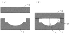
- (A) is a schematic diagram showing the cross section of the metal mold
- (B) is a schematic diagram showing the cross-sectional shape of the optical lens obtained using this metal mold
- (A) represents an open state, and (b) represents a closed state. It is a schematic diagram showing the cross section of the metal mold
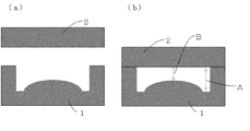
- (A) represents an open state, and (b) represents a closed state.
- (A) represents an open state, and (b) represents a closed state.
- (A) represents an open state, and (b) represents a closed state. It is a schematic diagram showing the cross section of the metal mold
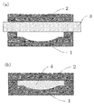
- (A) represents an open state, and (b) represents a closed state. It is a schematic diagram showing the vacuum compression molding
- the method for producing an optical lens of the present invention is a method in which a resin sheet is vacuum compression molded in a mold, and the glass transition temperature (Tg) of the resin sheet is 100 to 200 ° C., and the deepest part of the mold
- Tg glass transition temperature
- X 1 maximum thickness
- Tg represents the same meaning as described above, and t represents the value of T (° C.). It is characterized by satisfying.
- FIG. Fig.1 (a) is a schematic diagram of the metal mold
- the mold shown in FIG. 1A is composed of a lower mold (1) and an upper mold (2).
- the space in the mold can be reduced in pressure during molding.
- the inside of the mold can be connected to a vacuuming apparatus (not shown) installed outside, and the inside of the mold can be in a reduced pressure state during molding using the vacuuming apparatus.
- the shape, size, material, etc. of the mold are not particularly limited, and can be appropriately determined according to the shape, characteristics, etc. of the target optical lens.
- the depth (H 1 ) of the deepest part of the mold corresponds to the thickest part of the optical lens
- the depth (H 2 ) of the shallowest part of the mold is the optical lens. It corresponds to the thinnest part of.
- H 1 is the length of the portion indicated by arrow A
- H 2 is the length of the portion indicated by arrow B, respectively. is there.
- the value of H 1 is usually 0.5 mm or less, preferably 0.05 to 0.4 mm.
- the value of H 2 is usually 0.05 mm or more, preferably 0.05 to 0.35 mm.
- the difference between the value of H 1 and the value of H 2 is usually 0.01 to 0.4 mm, preferably 0.01 to 0.03 mm.
- the diameter of the mold (a value corresponding to the diameter of the optical lens) is usually 2 to 15 mm, preferably 3 to 10 mm.
- a resin sheet is used as a molding material.
- the resin constituting the resin sheet is not particularly limited as long as it is a thermoplastic resin. Even in the case of a thermosetting resin such as a crosslinkable polyolefin resin, the crosslinked structure is not sufficiently formed in the state of the resin sheet, and is melted by heating. Any resin that can be used (cured resin) can be used in the present invention.
- thermoplastic resin examples include (meth) acrylic resins, alicyclic structure-containing resins, styrene resins, polycarbonate resins, polyester resins, polyether resins, urethane resins, and thiourethane resins.
- an alicyclic structure-containing resin is preferably used because an optical lens having excellent transparency can be obtained.
- the alicyclic structure-containing resin is a polymer having an alicyclic structure in the main chain and / or side chain.
- the alicyclic structure include a saturated cyclic hydrocarbon (cycloalkane) structure and an unsaturated cyclic hydrocarbon (cycloalkene) structure.
- cycloalkane saturated cyclic hydrocarbon
- cycloalkene unsaturated cyclic hydrocarbon
- a cycloalkane structure is preferable because an optical lens excellent in mechanical strength and heat resistance can be easily obtained.
- the alicyclic structure may be in the main chain or in the side chain, but it is easy to obtain an optical lens having excellent mechanical strength and heat resistance, so that the main chain has an alicyclic structure. preferable.
- the number of carbon atoms constituting the alicyclic structure is not particularly limited, but is usually in the range of 4 to 30, preferably 5 to 20, and more preferably 5 to 15. When the number of carbon atoms constituting the alicyclic structure is within these ranges, it becomes easy to obtain an optical lens in which characteristics such as mechanical strength and heat resistance are highly balanced.
- the ratio of the repeating unit having an alicyclic structure in the alicyclic structure-containing polymer is not particularly limited, but is preferably 50% by weight or more, more preferably 70% by weight or more, and 90% by weight with respect to all the repeating units. The above is more preferable.
- an alicyclic structure-containing polymer in which the proportion of the repeating unit having an alicyclic structure is 50% by weight or more an optical lens having excellent transparency and heat resistance can be easily obtained.
- the weight average molecular weight (Mw) of the alicyclic structure-containing polymer is not particularly limited, but is usually 5,000 to 150,000, preferably 10,000 to 100,000.
- the weight average molecular weight (Mw) of the alicyclic structure-containing polymer can be determined, for example, as a standard polystyrene equivalent value by measuring at 40 ° C. using cyclohexane as a solvent.
- the glass transition temperature (Tg) of the alicyclic structure-containing polymer is not particularly limited, but is usually 100 to 200 ° C, preferably 120 to 160 ° C.
- the alicyclic structure-containing polymer examples include (1) a norbornene polymer, (2) a monocyclic olefin polymer, (3) a cyclic conjugated diene polymer, and (4) a vinyl alicyclic polymer.
- examples thereof include hydrocarbon polymers.
- norbornene-based polymers and vinyl alicyclic hydrocarbon-based polymers are preferable from the viewpoints of heat resistance, mechanical strength, and the like. In the present specification, these polymers mean not only polymerization reaction products but also their hydrides.
- the norbornene-based polymer is a polymer of a norbornene-based monomer or a hydride thereof.
- a ring-opening polymer of a norbornene-based monomer a ring-opening polymer of a norbornene-based monomer and another monomer capable of ring-opening copolymerization, a hydride of these ring-opening polymers, a norbornene-based polymer
- Examples thereof include addition polymers of monomers, addition polymers of norbornene monomers and other monomers copolymerizable therewith.
- a ring-opening polymer hydride of a norbornene monomer is preferable because an optical lens excellent in heat resistance, mechanical strength, and the like can be easily obtained.
- norbornene-based monomer examples include bicyclo [2.2.1] hept-2-ene (common name: norbornene) and its derivatives (having a substituent in the ring), tricyclo [4.3.0 1,6 . 1 2,5 ] deca-3,7-diene (common name dicyclopentadiene) and derivatives thereof, 7,8-benzotricyclo [4.3.0.1 2,5 ] dec-3-ene (common name) Methanotetrahydrofluorene: 1,4-methano-1,4,4a, 9a-tetrahydrofluorene) and its derivatives, tetracyclo [4.4.0.1 2,5 .
- dodec-3-ene (common name: tetracyclododecene) and its derivatives.
- substituent include an alkyl group, an alkylene group, a vinyl group, an alkoxycarbonyl group, and an alkylidene group.
- norbornene-based monomer having a substituent include 8-methoxycarbonyl-tetracyclo [4.4.0.1 2,5 . 1 7,10 ] dodec-3-ene, 8-methyl-8-methoxycarbonyl-tetracyclo [4.4.0.1 2,5 . 1 7,10 ] dodec-3-ene, 8-ethylidene-tetracyclo [4.4.0.1 2,5 . 1 7,10 ] dodec-3-ene and the like.
- These norbornene monomers can be used singly or in combination of two or more.
- monomers capable of ring-opening copolymerization with norbornene monomers include monocyclic olefin monomers such as cyclohexene, cycloheptene, and cyclooctene.
- ⁇ -olefins having 2 to 20 carbon atoms such as ethylene, propylene, 1-butene, 1-pentene, 1-hexene, and derivatives thereof; cyclobutene, cyclopentene , Cyclohexene, cyclooctene, cycloolefins such as 3a, 5,6,7a-tetrahydro-4,7-methano-1H-indene, and derivatives thereof; 1,4-hexadiene, 4-methyl-1,4-hexadiene , Non-conjugated dienes such as 5-methyl-1,4-hexadiene and 1,7-octadiene; Among these, ⁇ -olefin is preferable, and ethylene is more preferable.
- a ring-opening polymer of a norbornene-based monomer, or a ring-opening polymer of a norbornene-based monomer and another monomer capable of ring-opening copolymerization thereof, is obtained by polymerizing the monomer component in the presence of a known ring-opening polymerization catalyst. Can be synthesized.
- a catalyst comprising a metal halide such as ruthenium or osmium and a nitrate or acetylacetone compound and a reducing agent, or a metal halide or acetylacetone such as titanium, zirconium, tungsten or molybdenum
- a catalyst composed of a compound and an organoaluminum compound examples thereof include a catalyst composed of a compound and an organoaluminum compound.
- the ring-opening polymer hydride of a norbornene monomer is usually prepared by adding a known hydrogenation catalyst containing a transition metal such as nickel or palladium to the polymerization solution of the above-mentioned ring-opening polymer to form a carbon-carbon unsaturated bond. Can be obtained.
- An addition polymer of a norbornene monomer or an addition polymer of a norbornene monomer and another monomer copolymerizable therewith can be synthesized by polymerizing the monomer component in the presence of a known addition polymerization catalyst.
- a known addition polymerization catalyst include a catalyst composed of a titanium, zirconium or vanadium compound and an organoaluminum compound.
- monocyclic cycloolefin polymer examples include addition polymers of monocyclic cycloolefin monomers such as cyclohexene, cycloheptene, and cyclooctene.
- a method for synthesizing these addition polymers is not particularly limited, and a known method can be appropriately used.
- Cyclic conjugated diene polymer for example, a polymer obtained by subjecting a cyclic conjugated diene monomer such as cyclopentadiene or cyclohexadiene to 1,2- or 1,4-addition polymerization, and The hydride can be used.
- a method for synthesizing these addition polymers is not particularly limited, and a known method can be appropriately used.
- vinyl alicyclic hydrocarbon-based polymers include polymers of vinyl alicyclic hydrocarbon monomers such as vinylcyclohexene and vinylcyclohexane, and hydrogenated products thereof. Hydrides of aromatic ring portions of polymers of vinyl aromatic monomers such as styrene and ⁇ -methylstyrene; and the like. Further, it may be a copolymer of a vinyl alicyclic hydrocarbon monomer or vinyl aromatic monomer and another monomer copolymerizable with these monomers. Examples of such a copolymer include a random copolymer and a block copolymer. The method for synthesizing these polymers is not particularly limited, and known methods can be used as appropriate.
- a commercial item can also be used as an alicyclic structure containing polymer.
- Commercially available products include ZEON Corporation, ZEONEX (registered trademark), Mitsui Chemicals, APEL (registered trademark), JSR, ARTON (registered trademark), Polyplastics, TOPAS (registered trademark), etc. Can be mentioned.
- the resin sheet used as the molding material may contain components other than the resin component.
- components other than the resin component include additives such as a light stabilizer, an ultraviolet absorber, an antioxidant, a release agent, and an antistatic agent.
- the compounding amounts of these components are not particularly limited and can be determined as appropriate. For example, the total amount of these additives is 10% by weight or less based on the resin component.
- the manufacturing method of the resin sheet is not particularly limited, and a conventionally known appropriate method may be adopted.
- a molding material for producing a resin sheet is obtained by mixing predetermined components, and a resin sheet can be obtained by using this, by a melt extrusion molding method, a melt casting molding method, an injection molding method, or the like.
- a resin sheet having a predetermined thickness is used in accordance with the shape of the mold, and the thickness is usually 50 to 500 ⁇ m, preferably 70 to 400 ⁇ m.
- the resin sheet to be used may be flat, or have a projection that matches the mold (that is, the thickness of the portion corresponding to the concave portion of the mold is larger than the other portions). A thick one).
- a protrusion is provided on the resin sheet in accordance with the concave portion of the mold, a separate process is required for that purpose. Therefore, it is preferable to use a flat resin sheet from the viewpoint of more efficiently and inexpensively manufacturing an optical lens.
- the difference between the maximum thickness (X 1 ) and the minimum thickness (X 2 ) of the resin sheet used in the production method of the present invention is preferably 10 ⁇ m or less, and more preferably 5 ⁇ m or less. There is no particular lower limit to this difference, and the smaller the difference, the better. However, the difference between the maximum thickness (X 1 ) and the minimum thickness (X 2 ) of the resin sheet is usually 0.5 ⁇ m or more. If it is such a resin sheet, acquisition is easy and an optical lens can be manufactured efficiently.
- the glass transition temperature (Tg) of the resin sheet used in the production method of the present invention is 100 to 200 ° C., preferably 120 to 160 ° C.
- the obtained optical lens is inferior in heat resistance.
- the optical lens obtained when the glass transition temperature of the resin sheet exceeds 200 ° C. tends to be inferior in shape accuracy due to the influence of heat in the manufacturing process.
- the glass transition temperature (Tg) of the resin sheet can be measured by the method described in the examples.
- the resin sheet is vacuum compression molded in a mold.
- Vacuum compression molding is a molding method using a thermoplastic resin sheet as a molding material. The resin sheet is placed in a mold, and the mold is heated to soften the thermoplastic resin sheet by heating. This is a molding method in which the inside of the mold is decompressed, the sheet is brought into close contact with the mold and molded into a predetermined shape, and after cooling, the vacuum state is released and the resin molded product is taken out.
- the resin sheet (3) is sandwiched between the lower mold (1) and the upper mold (2), and the lower mold (1) and the upper mold (2) are fixed to each other.
- h 1 represents the value of H 1 ( ⁇ m)
- x 1 represents the value of X 1 ( ⁇ m).
- H 1 and X 1 satisfy the following formula (Ia).
- h 1 represents the value of H 1 ( ⁇ m)
- x 1 represents the value of X 1 ( ⁇ m).
- vacuum compression molding is performed so that the surface temperature (T) of the mold and the glass transition temperature (Tg) of the resin sheet satisfy the following formula (II). .
- Tg represents the glass transition temperature of the resin sheet
- t represents the value of T (° C.).
- the amount of the resin sheet to be used is not particularly limited as long as it can sufficiently fill the mold. Usually, it is preferable to use a resin sheet having a larger area than the area of the opening of the mold.
- the degree of vacuum in the mold at the time of vacuum compression molding is usually 10,000 Pa or less, and the mold compression time is usually 5 to 120 seconds.
- the cooling temperature of the mold is usually in the range of (Tg-30 ° C.) to (Tg-3 ° C.) (Tg represents the same meaning as described above).
- the lens obtained by the production method of the present invention is not particularly limited. Examples thereof include a plano-convex lens, a biconvex lens, a convex meniscus lens, a plano-concave lens, a biconcave lens, and a concave meniscus lens.
- the manufacturing method of this invention is preferably used when manufacturing convex lenses, such as a planoconvex lens, a biconvex lens, and a convex meniscus lens.
- the optical lens obtained by the production method of the present invention does not use an injection molding method, it is excellent in low birefringence, has no weld line, and has high shape accuracy.
- the retardation within the effective diameter of the optical lens obtained by the production method of the present invention is preferably 100 nm or less, and more preferably 50 nm or less.
- the shape error [PV (Peak to Valley) value] in the X direction and the Y direction of the optical lens obtained by the production method of the present invention is preferably 1.0 ⁇ m or less, and more preferably 0.5 ⁇ m or less.
- Tg Glass transition temperature of resin sheet
- the glass transition temperature (Tg) of the resin sheet was measured using a differential scanning calorimeter (product name “DSC6220SII”, manufactured by Nanotechnology Co., Ltd.) based on JIS K6911 at a temperature increase rate of 10 ° C./min.
- the shape accuracy (“NH-3SP”, manufactured by Mitaka Kogyo Co., Ltd.) was used to measure the lens shape accuracy (shape errors in the X and Y directions of the lens) obtained in the examples and comparative examples. Measured.
- Examples 2 to 4 Comparative Examples 1 to 7
- An optical lens was produced in the same manner as in Example 1 except that the thickness and molding conditions of the resin sheet were changed to those shown in Table 1, and various measurements were performed. The measurement results are shown in Table 1.
- the optical lenses obtained in Examples 1 to 4 have small birefringence and excellent shape accuracy.
- the optical lenses obtained in Comparative Examples 1 and 5 in which the mold surface temperature is too low have large birefringence and inferior shape accuracy.
- the optical lenses of Comparative Examples 2 and 4 obtained by using a resin sheet having a maximum thickness (X 1 ) that is too large in relation to the depth (H 1 ) of the deepest part of the mold has a large birefringence, and shape accuracy It is inferior to.
- the optical lenses of Comparative Examples 3 and 7 obtained using a resin sheet having a maximum thickness (X 1 ) that is too small in relation to the depth (H 1 ) of the deepest part of the mold is inferior in shape accuracy. .
- the optical lens obtained in Comparative Example 6 in which the mold surface temperature is too high is inferior in shape accuracy.
Landscapes
- Engineering & Computer Science (AREA)
- Mechanical Engineering (AREA)
- Casting Or Compression Moulding Of Plastics Or The Like (AREA)
- Moulds For Moulding Plastics Or The Like (AREA)
Abstract
本発明は、樹脂シートを、金型内で真空圧縮成形する光学レンズの製造方法であって、樹脂シートのガラス転移温度(Tg)が、100~200℃であり、金型の最深部の深さ(H1)と樹脂シートの最大厚み(X1)が、特定の関係式を充足し、真空圧縮成形時の金型の表面温度(T)と樹脂シートのガラス転移温度(Tg)が、特定の関係式を充足することを特徴とする光学レンズの製造方法である。本発明によれば、低複屈折性を有し、形状精度が高い光学レンズを、真空圧縮成形法により効率よく製造することができる。
Description
本発明は、低複屈折性を有し、形状精度が高い光学レンズを真空圧縮成形法により製造する光学レンズの製造方法に関する。
近年、電子電気機器の軽量化、小型化、薄型化が進み、携帯電話類に搭載されるカメラユニットにおいても、薄型・小径化が求められている。また、このようなカメラユニットにおいては、F値特性(絞り値)及びMTF特性(コントラスト再現比)等のレンズ性能に優れることも求められている。
従来、このようなカメラユニットに採用されるレンズは、大量生産し得ることが望ましいことから、射出成形法により製造されてきた。
しかしながら、射出成形法によりレンズを形成する場合、ウェルドラインや複屈折の不均一化が生じるため、光学有効面を広げることが難しく、直径が1cmに満たないような小径のレンズを射出成形法により製造することは困難であった。
従来、このようなカメラユニットに採用されるレンズは、大量生産し得ることが望ましいことから、射出成形法により製造されてきた。
しかしながら、射出成形法によりレンズを形成する場合、ウェルドラインや複屈折の不均一化が生じるため、光学有効面を広げることが難しく、直径が1cmに満たないような小径のレンズを射出成形法により製造することは困難であった。
このため、射出成形法以外の方法により、小径のレンズを製造する方法が検討されてきた。
例えば、特許文献1には、突起を有する樹脂シートを成形材料として用いて、この樹脂シートをレンズ金型内で真空圧縮成形することを特徴とする光学レンズの製造方法が提案されている。
例えば、特許文献1には、突起を有する樹脂シートを成形材料として用いて、この樹脂シートをレンズ金型内で真空圧縮成形することを特徴とする光学レンズの製造方法が提案されている。
特許文献1に記載の方法を用いることで、射出成形法を使用することなく、精度よく光学レンズを製造することができる。
しかしながら、この方法においては、樹脂シートに突起を設ける必要があるため、製造工程が煩雑になり、費用もかかるという問題があった。
したがって、真空圧縮成形法を用いて、より効率よく光学レンズを製造し得る方法が要望されていた。
しかしながら、この方法においては、樹脂シートに突起を設ける必要があるため、製造工程が煩雑になり、費用もかかるという問題があった。
したがって、真空圧縮成形法を用いて、より効率よく光学レンズを製造し得る方法が要望されていた。
本発明は、上記した実情に鑑みてなされたものであり、低複屈折性を有し、形状精度が高い光学レンズを、真空圧縮成形法により効率よく製造する光学レンズの製造方法を提供することを目的とする。
本発明者は上記課題を解決すべく、真空圧縮成形法により光学レンズを製造する方法について鋭意検討した。その結果、使用する金型に応じて適切な厚みの樹脂シートを使用し、さらに、その樹脂シートのガラス転移温度に応じて金型温度を調節することにより、突起を有しない通常の樹脂シートを成形材料として用いる場合であっても、低複屈折性を有し、形状精度が高い光学レンズを効率よく製造することができることを見出し、本発明を完成するに至った。
かくして本発明によれば、下記(1)~(4)の光学レンズの製造方法が提供される。
(1)樹脂シートを、金型内で真空圧縮成形する光学レンズの製造方法であって、樹脂シートのガラス転移温度(Tg)が、100~200℃であり、金型の最深部の深さ(H1)と樹脂シートの最大厚み(X1)が、下記式(I)
(1)樹脂シートを、金型内で真空圧縮成形する光学レンズの製造方法であって、樹脂シートのガラス転移温度(Tg)が、100~200℃であり、金型の最深部の深さ(H1)と樹脂シートの最大厚み(X1)が、下記式(I)

(式中、h1は前記H1の値(μm)を表し、x1は前記X1の値(μm)を表す。)
を充足し、真空圧縮成形時の金型の表面温度(T)と樹脂シートのガラス転移温度(Tg)が、下記式(II)
を充足し、真空圧縮成形時の金型の表面温度(T)と樹脂シートのガラス転移温度(Tg)が、下記式(II)

(式中、Tgは前記と同じ意味を表し、tは前記Tの値(℃)を表す。)
を充足することを特徴とする光学レンズの製造方法。
(2)前記樹脂シートを構成する樹脂成分が脂環構造含有重合体である、(1)に記載の光学レンズの製造方法。
(3)前記樹脂シートが、その最大厚み(X1)と最小厚み(X2)の差が、10μm以下のものである、(1)又は(2)に記載の光学レンズの製造方法。
(4)金型の最深部の深さ(H1)が0.5mm以下である、(1)~(3)のいずれかに記載の光学レンズの製造方法。
を充足することを特徴とする光学レンズの製造方法。
(2)前記樹脂シートを構成する樹脂成分が脂環構造含有重合体である、(1)に記載の光学レンズの製造方法。
(3)前記樹脂シートが、その最大厚み(X1)と最小厚み(X2)の差が、10μm以下のものである、(1)又は(2)に記載の光学レンズの製造方法。
(4)金型の最深部の深さ(H1)が0.5mm以下である、(1)~(3)のいずれかに記載の光学レンズの製造方法。
本発明の製造方法によれば、低複屈折性を有し、形状精度が高い光学レンズを真空圧縮成形法により効率よく製造することができる。
すなわち、本発明の製造方法によれば、使用する金型に応じて適切な厚みの樹脂シートを使用し、さらに、その樹脂シートのガラス転移温度に応じて金型温度を調節することにより、突起を有しない通常の樹脂シートを成形材料として用いる場合であっても、低複屈折性を有し、形状精度が高い光学レンズを、真空圧縮成形法により、効率よく製造することができる。
すなわち、本発明の製造方法によれば、使用する金型に応じて適切な厚みの樹脂シートを使用し、さらに、その樹脂シートのガラス転移温度に応じて金型温度を調節することにより、突起を有しない通常の樹脂シートを成形材料として用いる場合であっても、低複屈折性を有し、形状精度が高い光学レンズを、真空圧縮成形法により、効率よく製造することができる。
本発明の光学レンズの製造方法は、樹脂シートを、金型内で真空圧縮成形するものであって、樹脂シートのガラス転移温度(Tg)が、100~200℃であり、金型の最深部の深さ(H1)と樹脂シートの最大厚み(X1)が、下記式(I)

(式中、h1は前記H1の値(μm)を表し、x1は前記X1の値(μm)を表す。)
を充足し、真空圧縮成形時の金型の表面温度(T)と樹脂シートのガラス転移温度(Tg)が、下記式(II)
を充足し、真空圧縮成形時の金型の表面温度(T)と樹脂シートのガラス転移温度(Tg)が、下記式(II)

(式中、Tgは前記と同じ意味を表し、tは前記Tの値(℃)を表す。)
を充足することを特徴とするものである。
を充足することを特徴とするものである。
〔金型〕
本発明の製造方法に用いる金型としては、樹脂シートを成形材料とし、真空圧縮成形法により、目的の形状の光学レンズが得られるものであれば、特に限定されない。
本発明に用いる金型の一例を図1に示す。
図1(a)は、図1(b)に示す形状の光学レンズ(平凸レンズ)を製造するための金型の模式図である。
図1(a)に示す金型は、下部金型(1)と上部金型(2)とからなるものである。この金型内の空間は、成形時に減圧状態にすることができるようになっている。例えば、金型内部を外部に設置した真空引き装置(図示を省略)と連結させ、該真空引き装置を用いて、成形時に金型内部を減圧状態にすることができる。
本発明の製造方法に用いる金型としては、樹脂シートを成形材料とし、真空圧縮成形法により、目的の形状の光学レンズが得られるものであれば、特に限定されない。
本発明に用いる金型の一例を図1に示す。
図1(a)は、図1(b)に示す形状の光学レンズ(平凸レンズ)を製造するための金型の模式図である。
図1(a)に示す金型は、下部金型(1)と上部金型(2)とからなるものである。この金型内の空間は、成形時に減圧状態にすることができるようになっている。例えば、金型内部を外部に設置した真空引き装置(図示を省略)と連結させ、該真空引き装置を用いて、成形時に金型内部を減圧状態にすることができる。
金型の形状、大きさ、材質等は、特に限定されず、目的の光学レンズの形状、特性等に合わせて適宜決定することができる。
本発明において、金型の最深部の深さ(H1)とは、光学レンズの最も厚い部分に対応するものであり、金型の最浅部の深さ(H2)とは、光学レンズの最も薄い部分に対応するものである。例えば、図2、3、4に示した金型においては、H1は、それぞれ、矢印Aで示される部分の長さであり、H2は、それぞれ、矢印Bで示される部分の長さである。
前記H1の値は、通常、0.5mm以下であり、好ましくは0.05~0.4mmである。
前記H2の値は、通常、0.05mm以上であり、好ましくは0.05~0.35mmである。
また、H1の値とH2の値の差は、通常、0.01~0.4mm、好ましくは0.01~0.03mmである。
前記H2の値は、通常、0.05mm以上であり、好ましくは0.05~0.35mmである。
また、H1の値とH2の値の差は、通常、0.01~0.4mm、好ましくは0.01~0.03mmである。
金型の直径(光学レンズの直径に対応する値)は、通常2~15mmであり、好ましくは3~10mmである。
〔樹脂シート〕
本発明の製造方法においては、成形材料として樹脂シートを使用する。
樹脂シートを構成する樹脂は、熱可塑性樹脂であれば特に限定されない。また、架橋性ポリオレフィン樹脂のような熱硬化性樹脂であっても、樹脂シートの状態では架橋構造が十分に形成されておらず、加熱により溶融し、最終的に得られるレンズでは、架橋構造を有する樹脂(硬化樹脂)となるものであれば、本発明に使用することができる。
本発明の製造方法においては、成形材料として樹脂シートを使用する。
樹脂シートを構成する樹脂は、熱可塑性樹脂であれば特に限定されない。また、架橋性ポリオレフィン樹脂のような熱硬化性樹脂であっても、樹脂シートの状態では架橋構造が十分に形成されておらず、加熱により溶融し、最終的に得られるレンズでは、架橋構造を有する樹脂(硬化樹脂)となるものであれば、本発明に使用することができる。
熱可塑性を有する樹脂としては、(メタ)アクリル樹脂、脂環構造含有樹脂、スチレン系樹脂、ポリカーボネート樹脂、ポリエステル樹脂、ポリエーテル樹脂、ウレタン樹脂、チオウレタン樹脂等が挙げられる。
これらの中でも、透明性に優れる光学レンズが得られることから、脂環構造含有樹脂が好適に用いられる。
これらの中でも、透明性に優れる光学レンズが得られることから、脂環構造含有樹脂が好適に用いられる。
脂環構造含有樹脂とは、主鎖及び/又は側鎖に脂環式構造を有する重合体である。
脂環式構造としては、飽和環状炭化水素(シクロアルカン)構造、不飽和環状炭化水素(シクロアルケン)構造などが挙げられる。なかでも、機械強度、耐熱性に優れる光学レンズが得られ易いことから、シクロアルカン構造が好ましい。脂環式構造は主鎖にあっても良いし、側鎖にあっても良いが、機械強度、耐熱性に優れる光学レンズが得られ易いことから、主鎖に脂環式構造を有するものが好ましい。脂環式構造を構成する炭素原子数は特に限定されないが、通常4~30個、好ましくは5~20個、より好ましくは5~15個の範囲である。脂環式構造を構成する炭素原子数がこれらの範囲内であることで、機械強度、耐熱性等の特性が高度にバランスされた光学レンズが得られ易くなる。
脂環式構造としては、飽和環状炭化水素(シクロアルカン)構造、不飽和環状炭化水素(シクロアルケン)構造などが挙げられる。なかでも、機械強度、耐熱性に優れる光学レンズが得られ易いことから、シクロアルカン構造が好ましい。脂環式構造は主鎖にあっても良いし、側鎖にあっても良いが、機械強度、耐熱性に優れる光学レンズが得られ易いことから、主鎖に脂環式構造を有するものが好ましい。脂環式構造を構成する炭素原子数は特に限定されないが、通常4~30個、好ましくは5~20個、より好ましくは5~15個の範囲である。脂環式構造を構成する炭素原子数がこれらの範囲内であることで、機械強度、耐熱性等の特性が高度にバランスされた光学レンズが得られ易くなる。
脂環式構造含有重合体中の脂環式構造を有する繰り返し単位の割合は特に限定されないが、全繰り返し単位に対して、50重量%以上が好ましく、70重量%以上がより好ましく、90重量%以上がさらに好ましい。脂環式構造を有する繰り返し単位の割合が50重量%以上の脂環式構造含有重合体を用いることで、透明性および耐熱性に優れる光学レンズが得られ易くなる。
脂環式構造含有重合体の重量平均分子量(Mw)は、特に限定されないが、通常、5,000~150,000、好ましくは10,000~100,000である。
脂環式構造含有重合体の重量平均分子量(Mw)は、例えば、シクロヘキサンを溶媒として40℃で測定し、標準ポリスチレン換算値として求めることができる。
脂環式構造含有重合体のガラス転移温度(Tg)は、特に限定されないが、通常、100~200℃、好ましくは120~160℃である。
脂環式構造含有重合体の重量平均分子量(Mw)は、例えば、シクロヘキサンを溶媒として40℃で測定し、標準ポリスチレン換算値として求めることができる。
脂環式構造含有重合体のガラス転移温度(Tg)は、特に限定されないが、通常、100~200℃、好ましくは120~160℃である。
脂環式構造含有重合体の具体例としては、(1)ノルボルネン系重合体、(2)単環の環状オレフィン系重合体、(3)環状共役ジエン系重合体、(4)ビニル脂環式炭化水素系重合体などが挙げられる。これらの中でも、耐熱性、機械的強度等の観点から、ノルボルネン系重合体、及びビニル脂環式炭化水素系重合体が好ましい。
なお、本明細書において、これらの重合体は、重合反応生成物だけでなく、その水素化物も意味するものである。
なお、本明細書において、これらの重合体は、重合反応生成物だけでなく、その水素化物も意味するものである。
(1)ノルボルネン系重合体
ノルボルネン系重合体は、ノルボルネン系モノマーの重合体又はその水素化物である。
ノルボルネン系重合体としては、ノルボルネン系モノマーの開環重合体、ノルボルネン系モノマーとこれと開環共重合可能なその他のモノマーとの開環重合体、これらの開環重合体の水素化物、ノルボルネン系モノマーの付加重合体、ノルボルネン系モノマーとこれと共重合可能なその他のモノマーとの付加重合体などが挙げられる。なかでも、耐熱性、機械的強度等に優れる光学レンズが得られ易いことから、ノルボルネン系モノマーの開環重合体水素化物が好ましい。
ノルボルネン系重合体は、ノルボルネン系モノマーの重合体又はその水素化物である。
ノルボルネン系重合体としては、ノルボルネン系モノマーの開環重合体、ノルボルネン系モノマーとこれと開環共重合可能なその他のモノマーとの開環重合体、これらの開環重合体の水素化物、ノルボルネン系モノマーの付加重合体、ノルボルネン系モノマーとこれと共重合可能なその他のモノマーとの付加重合体などが挙げられる。なかでも、耐熱性、機械的強度等に優れる光学レンズが得られ易いことから、ノルボルネン系モノマーの開環重合体水素化物が好ましい。
ノルボルネン系モノマーとしては、ビシクロ[2.2.1]ヘプト-2-エン(慣用名:ノルボルネン)及びその誘導体(環に置換基を有するもの)、トリシクロ[4.3.01,6.12,5]デカ-3,7-ジエン(慣用名ジシクロペンタジエン)及びその誘導体、7,8-ベンゾトリシクロ[4.3.0.12,5]デカ-3-エン(慣用名メタノテトラヒドロフルオレン:1,4-メタノ-1,4,4a,9a-テトラヒドロフルオレンともいう)及びその誘導体、テトラシクロ[4.4.0.12,5.17,10]ドデカ-3-エン(慣用名:テトラシクロドデセン)及びその誘導体、などが挙げられる。
置換基としては、アルキル基、アルキレン基、ビニル基、アルコキシカルボニル基、アルキリデン基などが挙げられる。
置換基を有するノルボルネン系モノマーとしては、8-メトキシカルボニル-テトラシクロ[4.4.0.12,5.17,10]ドデカ-3-エン、8-メチル-8-メトキシカルボニル-テトラシクロ[4.4.0.12,5.17,10]ドデカ-3-エン、8-エチリデン-テトラシクロ[4.4.0.12,5.17,10]ドデカ-3-エンなどが挙げられる。
これらのノルボルネン系モノマーは、1種単独であるいは2種以上を組み合わせて用いることができる。
置換基としては、アルキル基、アルキレン基、ビニル基、アルコキシカルボニル基、アルキリデン基などが挙げられる。
置換基を有するノルボルネン系モノマーとしては、8-メトキシカルボニル-テトラシクロ[4.4.0.12,5.17,10]ドデカ-3-エン、8-メチル-8-メトキシカルボニル-テトラシクロ[4.4.0.12,5.17,10]ドデカ-3-エン、8-エチリデン-テトラシクロ[4.4.0.12,5.17,10]ドデカ-3-エンなどが挙げられる。
これらのノルボルネン系モノマーは、1種単独であるいは2種以上を組み合わせて用いることができる。
ノルボルネン系モノマーと開環共重合可能なその他のモノマーとしては、シクロヘキセン、シクロヘプテン、シクロオクテンなどの単環の環状オレフィン系単量体などが挙げられる。
ノルボルネン系モノマーと付加共重合可能なその他のモノマーとしては、エチレン、プロピレン、1-ブテン、1-ペンテン、1-ヘキセンなどの炭素数2~20のα-オレフィン、及びこれらの誘導体;シクロブテン、シクロペンテン、シクロヘキセン、シクロオクテン、3a,5,6,7a-テトラヒドロ-4,7-メタノ-1H-インデンなどのシクロオレフィン、及びこれらの誘導体;1,4-ヘキサジエン、4-メチル-1,4-ヘキサジエン、5-メチル-1,4-ヘキサジエン、1,7-オクタジエンなどの非共役ジエン;などが挙げられる。これらの中でも、α-オレフィンが好ましく、エチレンがより好ましい。
ノルボルネン系モノマーの開環重合体、またはノルボルネン系モノマーとこれと開環共重合可能なその他のモノマーとの開環重合体は、モノマー成分を、公知の開環重合触媒の存在下で重合させることにより合成することができる。開環重合触媒としては、例えば、ルテニウム、オスミウムなどの金属のハロゲン化物と、硝酸塩またはアセチルアセトン化合物、及び還元剤とからなる触媒、あるいは、チタン、ジルコニウム、タングステン、モリブデンなどの金属のハロゲン化物またはアセチルアセトン化合物と、有機アルミニウム化合物とからなる触媒等が挙げられる。
ノルボルネン系モノマーの開環重合体水素化物は、通常、上記開環重合体の重合溶液に、ニッケル、パラジウムなどの遷移金属を含む公知の水素化触媒を添加し、炭素-炭素不飽和結合を水素化することにより得ることができる。
ノルボルネン系モノマーの開環重合体水素化物は、通常、上記開環重合体の重合溶液に、ニッケル、パラジウムなどの遷移金属を含む公知の水素化触媒を添加し、炭素-炭素不飽和結合を水素化することにより得ることができる。
ノルボルネン系モノマーの付加重合体、またはノルボルネン系モノマーとこれと共重合可能なその他のモノマーとの付加重合体は、モノマー成分を、公知の付加重合触媒の存在下で重合させることにより合成することができる。付加重合触媒としては、例えば、チタン、ジルコニウム又はバナジウム化合物と有機アルミニウム化合物とからなる触媒が挙げられる。
(2)単環の環状オレフィン系重合体
単環の環状オレフィン系重合体としては、例えば、シクロヘキセン、シクロヘプテン、シクロオクテンなどの、単環の環状オレフィン系単量体の付加重合体が挙げられる。
これらの付加重合体の合成方法は特に限定されず、公知の方法を適宜利用することができる。
単環の環状オレフィン系重合体としては、例えば、シクロヘキセン、シクロヘプテン、シクロオクテンなどの、単環の環状オレフィン系単量体の付加重合体が挙げられる。
これらの付加重合体の合成方法は特に限定されず、公知の方法を適宜利用することができる。
(3)環状共役ジエン系重合体
環状共役ジエン系重合体としては、例えば、シクロペンタジエン、シクロヘキサジエンなどの環状共役ジエン系単量体を1,2-または1,4-付加重合した重合体及びその水素化物などを用いることができる。
これらの付加重合体の合成方法は特に限定されず、公知の方法を適宜利用することができる。
環状共役ジエン系重合体としては、例えば、シクロペンタジエン、シクロヘキサジエンなどの環状共役ジエン系単量体を1,2-または1,4-付加重合した重合体及びその水素化物などを用いることができる。
これらの付加重合体の合成方法は特に限定されず、公知の方法を適宜利用することができる。
(4)ビニル脂環式炭化水素系重合体
ビニル脂環式炭化水素系重合体としては、例えば、ビニルシクロヘキセン、ビニルシクロヘキサンなどのビニル脂環式炭化水素系単量体の重合体及びその水素化物;スチレン、α-メチルスチレンなどのビニル芳香族系単量体の重合体の芳香環部分の水素化物;などが挙げられる。また、ビニル脂環式炭化水素系単量体やビニル芳香族系単量体と、これらの単量体と共重合可能な他の単量体との共重合体であってもよい。かかる共重合体としては、ランダム共重合体、ブロック共重合体等が挙げられる。
これらの重合体の合成方法は特に限定されず、公知の方法を適宜利用することができる。
ビニル脂環式炭化水素系重合体としては、例えば、ビニルシクロヘキセン、ビニルシクロヘキサンなどのビニル脂環式炭化水素系単量体の重合体及びその水素化物;スチレン、α-メチルスチレンなどのビニル芳香族系単量体の重合体の芳香環部分の水素化物;などが挙げられる。また、ビニル脂環式炭化水素系単量体やビニル芳香族系単量体と、これらの単量体と共重合可能な他の単量体との共重合体であってもよい。かかる共重合体としては、ランダム共重合体、ブロック共重合体等が挙げられる。
これらの重合体の合成方法は特に限定されず、公知の方法を適宜利用することができる。
また、脂環式構造含有重合体として、市販品を使用することもできる。市販品としては、日本ゼオン社製、ZEONEX(登録商標)、三井化学社製、APEL(登録商標)、JSR社製、ARTON(登録商標)、ポリプラスチックス社製、TOPAS(登録商標)などが挙げられる。
成形材料として使用する樹脂シートは、樹脂成分以外の成分を含有するものであってもよい。
樹脂成分以外の成分としては、光安定剤、紫外線吸収剤、酸化防止剤、離型剤、帯電防止剤等の添加剤が挙げられる。
これらの成分の配合量は、特に限定されず適宜決定することができる。例えば、これらの添加剤の合計量は、樹脂成分に対して、10重量%以下である。
樹脂成分以外の成分としては、光安定剤、紫外線吸収剤、酸化防止剤、離型剤、帯電防止剤等の添加剤が挙げられる。
これらの成分の配合量は、特に限定されず適宜決定することができる。例えば、これらの添加剤の合計量は、樹脂成分に対して、10重量%以下である。
樹脂シートの製造方法は特に限定されず、従来公知の適宜な方法を採用すればよい。例えば、所定の成分を混合して樹脂シート製造用の成形材料を得、これを用いて、溶融押出成形法、溶融流延成形法、射出成形法等により、樹脂シートを得ることができる。
後述するように、本発明の製造方法においては、金型の形状に合わせて、所定の厚みの樹脂シートを用いるが、その厚みは、通常、50~500μm、好ましくは70~400μmである。
本発明の製造方法においては、用いる樹脂シートは平坦なものであってもよいし、金型に合わせた突起を有するもの(すなわち、金型の凹部に対応する部分の厚みが他の部分よりも厚いもの)であってもよい。ただし、金型の凹部に合わせて樹脂シートに突起を設けると、そのために別途工程が必要になる。したがって、より効率よく、安価に光学レンズを製造することができる観点から、平坦な樹脂シートを用いることが好ましい。
本発明の製造方法に用いる樹脂シートの最大厚み(X1)と最小厚み(X2)の差は、10μm以下が好ましく、5μm以下がより好ましい。この差の下限は特になく、この差は小さいほど好ましいが、樹脂シートの最大厚み(X1)と最小厚み(X2)の差は通常は、0.5μm以上である。
このような樹脂シートであれば、入手が容易であり、また、光学レンズを効率よく製造することができる。
このような樹脂シートであれば、入手が容易であり、また、光学レンズを効率よく製造することができる。
本発明の製造方法に用いる樹脂シートのガラス転移温度(Tg)は、100~200℃であり、120~160℃が好ましい。
用いる樹脂シートのガラス転移温度(Tg)が100℃未満のときは、得られる光学レンズは耐熱性に劣るものとなる。一方、樹脂シートのガラス転移温度が200℃を超えると得られる光学レンズは、その製造工程における熱の影響から形状精度に劣り易くなる。
樹脂シートのガラス転移温度(Tg)は、実施例に記載の方法により測定することができる。
用いる樹脂シートのガラス転移温度(Tg)が100℃未満のときは、得られる光学レンズは耐熱性に劣るものとなる。一方、樹脂シートのガラス転移温度が200℃を超えると得られる光学レンズは、その製造工程における熱の影響から形状精度に劣り易くなる。
樹脂シートのガラス転移温度(Tg)は、実施例に記載の方法により測定することができる。
〔光学レンズの製造方法〕
本発明の光学レンズの製造方法においては、前記樹脂シートを金型内で真空圧縮成形する。
真空圧縮成形とは、熱可塑性の樹脂シートを成形材料とする成形法であって、金型内に樹脂シートを載置し、金型を加熱して熱可塑性の樹脂シートを加熱軟化させ、金型内を減圧状態にして、シートを型に密着させて所定の形状に成形し、冷却後真空状態を解除して樹脂成形品を取り出す成形方法である。例えば、図5(a)に示すように、下部金型(1)と上部金型(2)で樹脂シート(3)を挟み込み、下部金型(1)、上部金型(2)を所定の温度に加熱して樹脂シートを軟化させる。この状態で金型を閉じ、金型内部を減圧にして、溶融樹脂(樹脂シート)を圧縮成形した後、金型を冷却することで、所定の形状の成形品(4)を得る〔図5(b)〕。次いで、成形品(4)を取り出し、必要に応じて端部の加工を施すことにより、目的の光学レンズを得ることができる。
本発明の光学レンズの製造方法においては、前記樹脂シートを金型内で真空圧縮成形する。
真空圧縮成形とは、熱可塑性の樹脂シートを成形材料とする成形法であって、金型内に樹脂シートを載置し、金型を加熱して熱可塑性の樹脂シートを加熱軟化させ、金型内を減圧状態にして、シートを型に密着させて所定の形状に成形し、冷却後真空状態を解除して樹脂成形品を取り出す成形方法である。例えば、図5(a)に示すように、下部金型(1)と上部金型(2)で樹脂シート(3)を挟み込み、下部金型(1)、上部金型(2)を所定の温度に加熱して樹脂シートを軟化させる。この状態で金型を閉じ、金型内部を減圧にして、溶融樹脂(樹脂シート)を圧縮成形した後、金型を冷却することで、所定の形状の成形品(4)を得る〔図5(b)〕。次いで、成形品(4)を取り出し、必要に応じて端部の加工を施すことにより、目的の光学レンズを得ることができる。
本発明の光学レンズの製造方法においては、金型の最深部の深さ(H1)と樹脂シートの最大厚み(X1)が、下記式(I)を充足するようにして、真空圧縮成形を行う。

式(I)中、h1は前記H1の値(μm)を表し、x1は前記X1の値(μm)を表す。
x1が(0.9×h1)以下の場合、得られる光学レンズは形状精度に劣り易くなる。一方、x1が(1.1×h1)以上の場合も、得られる光学レンズは形状精度に劣り、さらに、低複屈折性にも劣り易くなる。
x1が(0.9×h1)以下の場合、得られる光学レンズは形状精度に劣り易くなる。一方、x1が(1.1×h1)以上の場合も、得られる光学レンズは形状精度に劣り、さらに、低複屈折性にも劣り易くなる。
本発明の効果がより得られ易いことから、H1とX1は、下記式(Ia)を充足することが好ましい。

式(Ia)中、h1は前記H1の値(μm)を表し、x1は前記X1の値(μm)を表す。
さらに、本発明の光学レンズの製造方法においては、金型の表面温度(T)と樹脂シートのガラス転移温度(Tg)が、下記式(II)を充足するようにして、真空圧縮成形を行う。

式(II)中、Tgは樹脂シートのガラス転移温度を表し、tは前記Tの値(℃)を表す。
tが(Tg+30)℃未満の場合、得られる光学レンズは低複屈折性に劣り易くなる。一方、tが(Tg+70)℃を超える場合、得られる光学レンズは形状精度に劣り易くなる。
tが(Tg+30)℃未満の場合、得られる光学レンズは低複屈折性に劣り易くなる。一方、tが(Tg+70)℃を超える場合、得られる光学レンズは形状精度に劣り易くなる。
用いる樹脂シートの量は、金型内を十分に満たすことができる量であれば特に限定されない。通常は、金型の開口部の面積よりも面積が広い樹脂シートを用いることが好ましい。
真空圧縮成形をする際における金型内の真空度は、通常、10000Pa以下であり、金型圧縮時間は通常、5~120秒である。
金型の冷却温度は、通常、(Tg-30℃)から(Tg-3℃)の範囲である(Tgは前記と同じ意味を表す。)。
金型の冷却温度は、通常、(Tg-30℃)から(Tg-3℃)の範囲である(Tgは前記と同じ意味を表す。)。
本発明の製造方法により得られるレンズは、特に限定されない。例えば、平凸レンズ、両凸レンズ、凸メニスカスレンズ、平凹レンズ、両凹レンズ、凹メニスカスレンズ等が挙げられる。なかでも、本発明の製造方法は、平凸レンズ、両凸レンズ、凸メニスカスレンズ等の凸レンズを製造する際に好ましく用いられる。
本発明の製造方法により得られる光学レンズは、射出成形法を利用しないものであるため、低複屈折性に優れ、かつ、ウェルドラインが発生せず、形状精度が高いものである。
本発明の製造方法により得られる光学レンズの有効径内の位相差は、100nm以下が好ましく、50nm以下がより好ましい。
本発明の製造方法により得られる光学レンズのX方向とY方向の形状誤差〔PV(Peak to Valley)値〕は、1.0μm以下が好ましく、0.5μm以下がより好ましい。
本発明の製造方法により得られる光学レンズの有効径内の位相差は、100nm以下が好ましく、50nm以下がより好ましい。
本発明の製造方法により得られる光学レンズのX方向とY方向の形状誤差〔PV(Peak to Valley)値〕は、1.0μm以下が好ましく、0.5μm以下がより好ましい。
以下、実施例及び比較例を挙げて、本発明をさらに詳細に説明する。なお、本発明はこれらの例に何ら限定されるものではない。以下において、「部」および「%」は特に断りのない限り、重量基準である。
・樹脂シートのガラス転移温度(Tg)
樹脂シートのガラス転移温度(Tg)は、示差走査熱量分析計(製品名「DSC6220SII」、ナノテクノロジー社製)を用いて、JIS K6911に基づき昇温速度10℃/分の条件で測定した。
樹脂シートのガラス転移温度(Tg)は、示差走査熱量分析計(製品名「DSC6220SII」、ナノテクノロジー社製)を用いて、JIS K6911に基づき昇温速度10℃/分の条件で測定した。
・レンズの形状精度
実施例及び比較例で得られたレンズの形状精度(レンズのX方向とY方向の形状誤差)を、形状測定器〔「NH-3SP」、三鷹光機社製〕を用いて測定した。
実施例及び比較例で得られたレンズの形状精度(レンズのX方向とY方向の形状誤差)を、形状測定器〔「NH-3SP」、三鷹光機社製〕を用いて測定した。
・レンズの位相差
実施例及び比較例で得られたレンズの有効径内の位相差を、樹脂成形レンズ検査システム〔「WPA-100」、フォトニックスラティス社製〕を用いて測定した。
実施例及び比較例で得られたレンズの有効径内の位相差を、樹脂成形レンズ検査システム〔「WPA-100」、フォトニックスラティス社製〕を用いて測定した。
〔実施例1〕
樹脂材料(ZEONEX E48R(日本ゼオン社製)、Tg=139℃)をフィルム押出成形機(単軸押出機、φ=20mm:GSIクレイオス社製)に入れ、これを260℃で溶融し、溶融樹脂をTダイから押し出し、これを冷却して、最大厚みが345μmでA4サイズ(210mm×297mm)の樹脂シートを得た。
樹脂材料(ZEONEX E48R(日本ゼオン社製)、Tg=139℃)をフィルム押出成形機(単軸押出機、φ=20mm:GSIクレイオス社製)に入れ、これを260℃で溶融し、溶融樹脂をTダイから押し出し、これを冷却して、最大厚みが345μmでA4サイズ(210mm×297mm)の樹脂シートを得た。
この樹脂シートを成形材料として使用し、真空熱加圧装置(製品名「VACUUM STAR(登録商標)、ミカドテクノス社製)にて、真空圧縮成形を行い、レンズを製造した。このレンズについて各種測定を行った。真空圧縮成形における成形条件及び測定結果を第1表に示す。
〔実施例2~4、比較例1~7〕
樹脂シートの厚みや成形条件を第1表に記載のものに変更したことを除き、実施例1と同様にして光学レンズを製造し、各種測定を行った。測定結果を第1表に示す。
樹脂シートの厚みや成形条件を第1表に記載のものに変更したことを除き、実施例1と同様にして光学レンズを製造し、各種測定を行った。測定結果を第1表に示す。
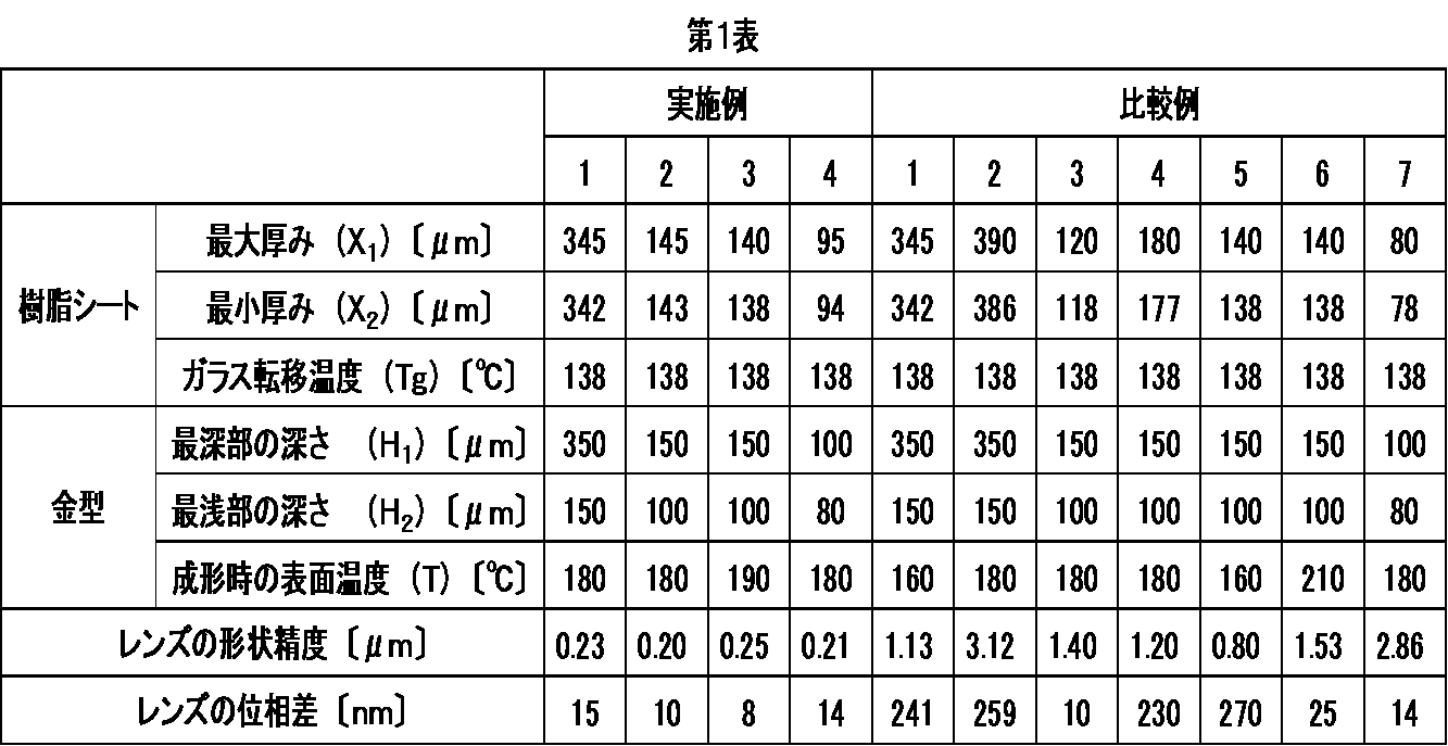
第1表から以下のことが分かる。
実施例1~4で得られた光学レンズは複屈折が小さく、形状精度に優れる。
一方、金型の表面温度が低すぎる比較例1、5で得られた光学レンズは、複屈折が大きく、形状精度に劣っている。
金型の最深部の深さ(H1)との関係で、最大厚み(X1)が大きすぎる樹脂シートを用いて得られた比較例2、4の光学レンズは複屈折が大きく、形状精度に劣っている。
金型の最深部の深さ(H1)との関係で、最大厚み(X1)が小さすぎる樹脂シートを用いて得られた比較例3、7の光学レンズは、形状精度に劣っている。
また、金型の表面温度が高すぎる比較例6で得られた光学レンズは、形状精度に劣っている。
実施例1~4で得られた光学レンズは複屈折が小さく、形状精度に優れる。
一方、金型の表面温度が低すぎる比較例1、5で得られた光学レンズは、複屈折が大きく、形状精度に劣っている。
金型の最深部の深さ(H1)との関係で、最大厚み(X1)が大きすぎる樹脂シートを用いて得られた比較例2、4の光学レンズは複屈折が大きく、形状精度に劣っている。
金型の最深部の深さ(H1)との関係で、最大厚み(X1)が小さすぎる樹脂シートを用いて得られた比較例3、7の光学レンズは、形状精度に劣っている。
また、金型の表面温度が高すぎる比較例6で得られた光学レンズは、形状精度に劣っている。
1.下部金型
2.上部金型
3.樹脂シート
4.成形品
A.金型の最深部の深さ(H1)
B.金型の最浅部の深さ(H2)
2.上部金型
3.樹脂シート
4.成形品
A.金型の最深部の深さ(H1)
B.金型の最浅部の深さ(H2)
Claims (4)
- 樹脂シートを、金型内で真空圧縮成形する光学レンズの製造方法であって、
樹脂シートのガラス転移温度(Tg)が、100~200℃であり、
金型の最深部の深さ(H1)と樹脂シートの最大厚み(X1)が、下記式(I)

を充足し、
真空圧縮成形時の金型の表面温度(T)と樹脂シートのガラス転移温度(Tg)が、下記式(II)

を充足することを特徴とする光学レンズの製造方法。 - 前記樹脂シートを構成する樹脂成分が脂環構造含有重合体である、請求項1に記載の光学レンズの製造方法。
- 前記樹脂シートが、その最大厚み(X1)と最小厚み(X2)の差が、10μm以下のものである、請求項1又は2に記載の光学レンズの製造方法。
- 金型の最深部の深さ(H1)が0.5mm以下である、請求項1~3のいずれかに記載の光学レンズの製造方法。
Priority Applications (1)
| Application Number | Priority Date | Filing Date | Title |
|---|---|---|---|
| JP2017562880A JP6844550B2 (ja) | 2016-01-22 | 2017-01-19 | 光学レンズの製造方法 |
Applications Claiming Priority (2)
| Application Number | Priority Date | Filing Date | Title |
|---|---|---|---|
| JP2016010604 | 2016-01-22 | ||
| JP2016-010604 | 2016-01-22 |
Publications (1)
| Publication Number | Publication Date |
|---|---|
| WO2017126599A1 true WO2017126599A1 (ja) | 2017-07-27 |
Family
ID=59361780
Family Applications (1)
| Application Number | Title | Priority Date | Filing Date |
|---|---|---|---|
| PCT/JP2017/001719 Ceased WO2017126599A1 (ja) | 2016-01-22 | 2017-01-19 | 光学レンズの製造方法 |
Country Status (3)
| Country | Link |
|---|---|
| JP (1) | JP6844550B2 (ja) |
| TW (1) | TWI737670B (ja) |
| WO (1) | WO2017126599A1 (ja) |
Cited By (3)
| Publication number | Priority date | Publication date | Assignee | Title |
|---|---|---|---|---|
| JPWO2021006126A1 (ja) * | 2019-07-10 | 2021-01-14 | ||
| JPWO2021065489A1 (ja) * | 2019-09-30 | 2021-04-08 | ||
| JPWO2021153512A1 (ja) * | 2020-01-29 | 2021-08-05 |
Citations (4)
| Publication number | Priority date | Publication date | Assignee | Title |
|---|---|---|---|---|
| JPS59123632A (ja) * | 1982-12-29 | 1984-07-17 | Matsushita Electric Ind Co Ltd | プラスチツク光学部品の製造方法 |
| JPH09267404A (ja) * | 1996-01-31 | 1997-10-14 | Matsushita Electric Ind Co Ltd | 加圧成形による光学素材及び光学素子の製造方法並びにプレス型 |
| JP2009202561A (ja) * | 2008-01-30 | 2009-09-10 | Fujifilm Corp | プレス加工用前駆体及びその製造方法 |
| JP2015116788A (ja) * | 2013-12-20 | 2015-06-25 | 日本ゼオン株式会社 | 光学レンズの成形方法 |
Family Cites Families (2)
| Publication number | Priority date | Publication date | Assignee | Title |
|---|---|---|---|---|
| JPH07323486A (ja) * | 1994-06-02 | 1995-12-12 | Ricoh Co Ltd | プラスチック成形品の製造方法 |
| JP4022923B2 (ja) * | 2004-05-20 | 2007-12-19 | コニカミノルタオプト株式会社 | 光学素子の成形方法 |
-
2017
- 2017-01-19 JP JP2017562880A patent/JP6844550B2/ja active Active
- 2017-01-19 WO PCT/JP2017/001719 patent/WO2017126599A1/ja not_active Ceased
- 2017-01-20 TW TW106102045A patent/TWI737670B/zh active
Patent Citations (4)
| Publication number | Priority date | Publication date | Assignee | Title |
|---|---|---|---|---|
| JPS59123632A (ja) * | 1982-12-29 | 1984-07-17 | Matsushita Electric Ind Co Ltd | プラスチツク光学部品の製造方法 |
| JPH09267404A (ja) * | 1996-01-31 | 1997-10-14 | Matsushita Electric Ind Co Ltd | 加圧成形による光学素材及び光学素子の製造方法並びにプレス型 |
| JP2009202561A (ja) * | 2008-01-30 | 2009-09-10 | Fujifilm Corp | プレス加工用前駆体及びその製造方法 |
| JP2015116788A (ja) * | 2013-12-20 | 2015-06-25 | 日本ゼオン株式会社 | 光学レンズの成形方法 |
Cited By (18)
| Publication number | Priority date | Publication date | Assignee | Title |
|---|---|---|---|---|
| CN113811433A (zh) * | 2019-07-10 | 2021-12-17 | 日本瑞翁株式会社 | 透射型光学元件的制造方法 |
| WO2021006126A1 (ja) * | 2019-07-10 | 2021-01-14 | 日本ゼオン株式会社 | 透過型光学素子の製造方法 |
| JP7593315B2 (ja) | 2019-07-10 | 2024-12-03 | 日本ゼオン株式会社 | 透過型光学素子の製造方法 |
| JPWO2021006126A1 (ja) * | 2019-07-10 | 2021-01-14 | ||
| CN113811433B (zh) * | 2019-07-10 | 2023-05-12 | 日本瑞翁株式会社 | 透射型光学元件的制造方法 |
| KR20220032010A (ko) | 2019-07-10 | 2022-03-15 | 니폰 제온 가부시키가이샤 | 투과형 광학 소자의 제조 방법 |
| EP4040198A4 (en) * | 2019-09-30 | 2023-11-01 | Zeon Corporation | RESIN FILM AND METHOD FOR PRODUCING IT |
| CN114302794A (zh) * | 2019-09-30 | 2022-04-08 | 日本瑞翁株式会社 | 树脂片和树脂片的制造方法 |
| US11654601B2 (en) | 2019-09-30 | 2023-05-23 | Zeon Corporation | Resin sheet and method of producing resin sheet |
| WO2021065489A1 (ja) | 2019-09-30 | 2021-04-08 | 日本ゼオン株式会社 | 樹脂シートおよび樹脂シートの製造方法 |
| CN114302794B (zh) * | 2019-09-30 | 2024-07-26 | 日本瑞翁株式会社 | 树脂片和树脂片的制造方法 |
| JP7589694B2 (ja) | 2019-09-30 | 2024-11-26 | 日本ゼオン株式会社 | 樹脂シートおよび樹脂シートの製造方法 |
| JPWO2021065489A1 (ja) * | 2019-09-30 | 2021-04-08 | ||
| WO2021153512A1 (ja) * | 2020-01-29 | 2021-08-05 | 日本ゼオン株式会社 | 成形シート及び成形シートの製造方法、並びに、光学素子の製造方法 |
| CN114786903A (zh) * | 2020-01-29 | 2022-07-22 | 日本瑞翁株式会社 | 成型片、成型片的制造方法、以及光学元件的制造方法 |
| JPWO2021153512A1 (ja) * | 2020-01-29 | 2021-08-05 | ||
| CN114786903B (zh) * | 2020-01-29 | 2025-02-25 | 日本瑞翁株式会社 | 成型片、成型片的制造方法、以及光学元件的制造方法 |
| JP7673645B2 (ja) | 2020-01-29 | 2025-05-09 | 日本ゼオン株式会社 | 成形シート及び成形シートの製造方法、並びに、光学素子の製造方法 |
Also Published As
| Publication number | Publication date |
|---|---|
| TWI737670B (zh) | 2021-09-01 |
| TW201736079A (zh) | 2017-10-16 |
| JPWO2017126599A1 (ja) | 2018-11-08 |
| JP6844550B2 (ja) | 2021-03-17 |
Similar Documents
| Publication | Publication Date | Title |
|---|---|---|
| JP6844550B2 (ja) | 光学レンズの製造方法 | |
| US9459376B2 (en) | Optical polymer and optical element obtained by forming thereof | |
| JP2016147502A (ja) | 光学レンズ成形用金型及び光学レンズの製造方法 | |
| TWI862618B (zh) | 穿透型光學元件之製造方法 | |
| JP7650689B2 (ja) | 光学部品の製造方法 | |
| JP5803322B2 (ja) | 樹脂組成物及び成形体 | |
| TWI851817B (zh) | 樹脂薄片及樹脂薄片的製造方法 | |
| JP5381827B2 (ja) | 硬化性組成物用複合樹脂型 | |
| CN114786903B (zh) | 成型片、成型片的制造方法、以及光学元件的制造方法 | |
| JP2015218277A (ja) | 光学フィルムの製造方法 | |
| JP2016112867A (ja) | 樹脂成形品の製造方法 | |
| JP2015124281A (ja) | 脂環構造含有重合体組成物及びその利用 | |
| JP2001038773A (ja) | 光学部品用成形体の成形方法 | |
| JP6229482B2 (ja) | 光学レンズの成形方法 | |
| JP7225799B2 (ja) | 透過型光学素子の製造方法 | |
| JP2007253379A (ja) | 板状成形体の製造方法 | |
| JP6264074B2 (ja) | 重合体組成物の製造方法 | |
| JP2007210192A (ja) | 成形体 | |
| JP2007015312A (ja) | 樹脂成形体の製造方法 |
Legal Events
| Date | Code | Title | Description |
|---|---|---|---|
| 121 | Ep: the epo has been informed by wipo that ep was designated in this application |
Ref document number: 17741476 Country of ref document: EP Kind code of ref document: A1 |
|
| ENP | Entry into the national phase |
Ref document number: 2017562880 Country of ref document: JP Kind code of ref document: A |
|
| NENP | Non-entry into the national phase |
Ref country code: DE |
|
| 122 | Ep: pct application non-entry in european phase |
Ref document number: 17741476 Country of ref document: EP Kind code of ref document: A1 |