WO2017126463A1 - ビークル - Google Patents
ビークル Download PDFInfo
- Publication number
- WO2017126463A1 WO2017126463A1 PCT/JP2017/001194 JP2017001194W WO2017126463A1 WO 2017126463 A1 WO2017126463 A1 WO 2017126463A1 JP 2017001194 W JP2017001194 W JP 2017001194W WO 2017126463 A1 WO2017126463 A1 WO 2017126463A1
- Authority
- WO
- WIPO (PCT)
- Prior art keywords
- engine
- crankshaft
- state
- starter generator
- vehicle
- Prior art date
Links
Images


Classifications
-
- B—PERFORMING OPERATIONS; TRANSPORTING
- B60—VEHICLES IN GENERAL
- B60K—ARRANGEMENT OR MOUNTING OF PROPULSION UNITS OR OF TRANSMISSIONS IN VEHICLES; ARRANGEMENT OR MOUNTING OF PLURAL DIVERSE PRIME-MOVERS IN VEHICLES; AUXILIARY DRIVES FOR VEHICLES; INSTRUMENTATION OR DASHBOARDS FOR VEHICLES; ARRANGEMENTS IN CONNECTION WITH COOLING, AIR INTAKE, GAS EXHAUST OR FUEL SUPPLY OF PROPULSION UNITS IN VEHICLES
- B60K6/00—Arrangement or mounting of plural diverse prime-movers for mutual or common propulsion, e.g. hybrid propulsion systems comprising electric motors and internal combustion engines ; Control systems therefor, i.e. systems controlling two or more prime movers, or controlling one of these prime movers and any of the transmission, drive or drive units Informative references: mechanical gearings with secondary electric drive F16H3/72; arrangements for handling mechanical energy structurally associated with the dynamo-electric machine H02K7/00; machines comprising structurally interrelated motor and generator parts H02K51/00; dynamo-electric machines not otherwise provided for in H02K see H02K99/00
- B60K6/20—Arrangement or mounting of plural diverse prime-movers for mutual or common propulsion, e.g. hybrid propulsion systems comprising electric motors and internal combustion engines ; Control systems therefor, i.e. systems controlling two or more prime movers, or controlling one of these prime movers and any of the transmission, drive or drive units Informative references: mechanical gearings with secondary electric drive F16H3/72; arrangements for handling mechanical energy structurally associated with the dynamo-electric machine H02K7/00; machines comprising structurally interrelated motor and generator parts H02K51/00; dynamo-electric machines not otherwise provided for in H02K see H02K99/00 the prime-movers consisting of electric motors and internal combustion engines, e.g. HEVs
- B60K6/42—Arrangement or mounting of plural diverse prime-movers for mutual or common propulsion, e.g. hybrid propulsion systems comprising electric motors and internal combustion engines ; Control systems therefor, i.e. systems controlling two or more prime movers, or controlling one of these prime movers and any of the transmission, drive or drive units Informative references: mechanical gearings with secondary electric drive F16H3/72; arrangements for handling mechanical energy structurally associated with the dynamo-electric machine H02K7/00; machines comprising structurally interrelated motor and generator parts H02K51/00; dynamo-electric machines not otherwise provided for in H02K see H02K99/00 the prime-movers consisting of electric motors and internal combustion engines, e.g. HEVs characterised by the architecture of the hybrid electric vehicle
- B60K6/48—Parallel type
- B60K6/485—Motor-assist type
-
- F—MECHANICAL ENGINEERING; LIGHTING; HEATING; WEAPONS; BLASTING
- F02—COMBUSTION ENGINES; HOT-GAS OR COMBUSTION-PRODUCT ENGINE PLANTS
- F02D—CONTROLLING COMBUSTION ENGINES
- F02D17/00—Controlling engines by cutting out individual cylinders; Rendering engines inoperative or idling
-
- F—MECHANICAL ENGINEERING; LIGHTING; HEATING; WEAPONS; BLASTING
- F02—COMBUSTION ENGINES; HOT-GAS OR COMBUSTION-PRODUCT ENGINE PLANTS
- F02D—CONTROLLING COMBUSTION ENGINES
- F02D29/00—Controlling engines, such controlling being peculiar to the devices driven thereby, the devices being other than parts or accessories essential to engine operation, e.g. controlling of engines by signals external thereto
- F02D29/02—Controlling engines, such controlling being peculiar to the devices driven thereby, the devices being other than parts or accessories essential to engine operation, e.g. controlling of engines by signals external thereto peculiar to engines driving vehicles; peculiar to engines driving variable pitch propellers
-
- F—MECHANICAL ENGINEERING; LIGHTING; HEATING; WEAPONS; BLASTING
- F02—COMBUSTION ENGINES; HOT-GAS OR COMBUSTION-PRODUCT ENGINE PLANTS
- F02D—CONTROLLING COMBUSTION ENGINES
- F02D41/00—Electrical control of supply of combustible mixture or its constituents
- F02D41/02—Circuit arrangements for generating control signals
- F02D41/04—Introducing corrections for particular operating conditions
- F02D41/08—Introducing corrections for particular operating conditions for idling
-
- F—MECHANICAL ENGINEERING; LIGHTING; HEATING; WEAPONS; BLASTING
- F02—COMBUSTION ENGINES; HOT-GAS OR COMBUSTION-PRODUCT ENGINE PLANTS
- F02N—STARTING OF COMBUSTION ENGINES; STARTING AIDS FOR SUCH ENGINES, NOT OTHERWISE PROVIDED FOR
- F02N11/00—Starting of engines by means of electric motors
- F02N11/08—Circuits or control means specially adapted for starting of engines
- F02N11/0814—Circuits or control means specially adapted for starting of engines comprising means for controlling automatic idle-start-stop
- F02N11/0818—Conditions for starting or stopping the engine or for deactivating the idle-start-stop mode
-
- B—PERFORMING OPERATIONS; TRANSPORTING
- B60—VEHICLES IN GENERAL
- B60K—ARRANGEMENT OR MOUNTING OF PROPULSION UNITS OR OF TRANSMISSIONS IN VEHICLES; ARRANGEMENT OR MOUNTING OF PLURAL DIVERSE PRIME-MOVERS IN VEHICLES; AUXILIARY DRIVES FOR VEHICLES; INSTRUMENTATION OR DASHBOARDS FOR VEHICLES; ARRANGEMENTS IN CONNECTION WITH COOLING, AIR INTAKE, GAS EXHAUST OR FUEL SUPPLY OF PROPULSION UNITS IN VEHICLES
- B60K6/00—Arrangement or mounting of plural diverse prime-movers for mutual or common propulsion, e.g. hybrid propulsion systems comprising electric motors and internal combustion engines ; Control systems therefor, i.e. systems controlling two or more prime movers, or controlling one of these prime movers and any of the transmission, drive or drive units Informative references: mechanical gearings with secondary electric drive F16H3/72; arrangements for handling mechanical energy structurally associated with the dynamo-electric machine H02K7/00; machines comprising structurally interrelated motor and generator parts H02K51/00; dynamo-electric machines not otherwise provided for in H02K see H02K99/00
- B60K6/20—Arrangement or mounting of plural diverse prime-movers for mutual or common propulsion, e.g. hybrid propulsion systems comprising electric motors and internal combustion engines ; Control systems therefor, i.e. systems controlling two or more prime movers, or controlling one of these prime movers and any of the transmission, drive or drive units Informative references: mechanical gearings with secondary electric drive F16H3/72; arrangements for handling mechanical energy structurally associated with the dynamo-electric machine H02K7/00; machines comprising structurally interrelated motor and generator parts H02K51/00; dynamo-electric machines not otherwise provided for in H02K see H02K99/00 the prime-movers consisting of electric motors and internal combustion engines, e.g. HEVs
- B60K6/22—Arrangement or mounting of plural diverse prime-movers for mutual or common propulsion, e.g. hybrid propulsion systems comprising electric motors and internal combustion engines ; Control systems therefor, i.e. systems controlling two or more prime movers, or controlling one of these prime movers and any of the transmission, drive or drive units Informative references: mechanical gearings with secondary electric drive F16H3/72; arrangements for handling mechanical energy structurally associated with the dynamo-electric machine H02K7/00; machines comprising structurally interrelated motor and generator parts H02K51/00; dynamo-electric machines not otherwise provided for in H02K see H02K99/00 the prime-movers consisting of electric motors and internal combustion engines, e.g. HEVs characterised by apparatus, components or means specially adapted for HEVs
- B60K6/26—Arrangement or mounting of plural diverse prime-movers for mutual or common propulsion, e.g. hybrid propulsion systems comprising electric motors and internal combustion engines ; Control systems therefor, i.e. systems controlling two or more prime movers, or controlling one of these prime movers and any of the transmission, drive or drive units Informative references: mechanical gearings with secondary electric drive F16H3/72; arrangements for handling mechanical energy structurally associated with the dynamo-electric machine H02K7/00; machines comprising structurally interrelated motor and generator parts H02K51/00; dynamo-electric machines not otherwise provided for in H02K see H02K99/00 the prime-movers consisting of electric motors and internal combustion engines, e.g. HEVs characterised by apparatus, components or means specially adapted for HEVs characterised by the motors or the generators
- B60K2006/268—Electric drive motor starts the engine, i.e. used as starter motor
-
- B—PERFORMING OPERATIONS; TRANSPORTING
- B60—VEHICLES IN GENERAL
- B60W—CONJOINT CONTROL OF VEHICLE SUB-UNITS OF DIFFERENT TYPE OR DIFFERENT FUNCTION; CONTROL SYSTEMS SPECIALLY ADAPTED FOR HYBRID VEHICLES; ROAD VEHICLE DRIVE CONTROL SYSTEMS FOR PURPOSES NOT RELATED TO THE CONTROL OF A PARTICULAR SUB-UNIT
- B60W2300/00—Indexing codes relating to the type of vehicle
- B60W2300/36—Cycles; Motorcycles; Scooters
- B60W2300/365—Scooters
-
- F—MECHANICAL ENGINEERING; LIGHTING; HEATING; WEAPONS; BLASTING
- F02—COMBUSTION ENGINES; HOT-GAS OR COMBUSTION-PRODUCT ENGINE PLANTS
- F02N—STARTING OF COMBUSTION ENGINES; STARTING AIDS FOR SUCH ENGINES, NOT OTHERWISE PROVIDED FOR
- F02N11/00—Starting of engines by means of electric motors
- F02N11/04—Starting of engines by means of electric motors the motors being associated with current generators
-
- F—MECHANICAL ENGINEERING; LIGHTING; HEATING; WEAPONS; BLASTING
- F02—COMBUSTION ENGINES; HOT-GAS OR COMBUSTION-PRODUCT ENGINE PLANTS
- F02N—STARTING OF COMBUSTION ENGINES; STARTING AIDS FOR SUCH ENGINES, NOT OTHERWISE PROVIDED FOR
- F02N11/00—Starting of engines by means of electric motors
- F02N11/08—Circuits or control means specially adapted for starting of engines
- F02N11/0814—Circuits or control means specially adapted for starting of engines comprising means for controlling automatic idle-start-stop
- F02N11/0818—Conditions for starting or stopping the engine or for deactivating the idle-start-stop mode
- F02N11/0829—Conditions for starting or stopping the engine or for deactivating the idle-start-stop mode related to special engine control, e.g. giving priority to engine warming-up or learning
-
- F—MECHANICAL ENGINEERING; LIGHTING; HEATING; WEAPONS; BLASTING
- F02—COMBUSTION ENGINES; HOT-GAS OR COMBUSTION-PRODUCT ENGINE PLANTS
- F02N—STARTING OF COMBUSTION ENGINES; STARTING AIDS FOR SUCH ENGINES, NOT OTHERWISE PROVIDED FOR
- F02N11/00—Starting of engines by means of electric motors
- F02N11/08—Circuits or control means specially adapted for starting of engines
- F02N11/0814—Circuits or control means specially adapted for starting of engines comprising means for controlling automatic idle-start-stop
- F02N11/0844—Circuits or control means specially adapted for starting of engines comprising means for controlling automatic idle-start-stop with means for restarting the engine directly after an engine stop request, e.g. caused by change of driver mind
-
- F—MECHANICAL ENGINEERING; LIGHTING; HEATING; WEAPONS; BLASTING
- F02—COMBUSTION ENGINES; HOT-GAS OR COMBUSTION-PRODUCT ENGINE PLANTS
- F02N—STARTING OF COMBUSTION ENGINES; STARTING AIDS FOR SUCH ENGINES, NOT OTHERWISE PROVIDED FOR
- F02N11/00—Starting of engines by means of electric motors
- F02N11/08—Circuits or control means specially adapted for starting of engines
- F02N2011/0881—Components of the circuit not provided for by previous groups
- F02N2011/0896—Inverters for electric machines, e.g. starter-generators
-
- F—MECHANICAL ENGINEERING; LIGHTING; HEATING; WEAPONS; BLASTING
- F02—COMBUSTION ENGINES; HOT-GAS OR COMBUSTION-PRODUCT ENGINE PLANTS
- F02N—STARTING OF COMBUSTION ENGINES; STARTING AIDS FOR SUCH ENGINES, NOT OTHERWISE PROVIDED FOR
- F02N2200/00—Parameters used for control of starting apparatus
- F02N2200/06—Parameters used for control of starting apparatus said parameters being related to the power supply or driving circuits for the starter
- F02N2200/061—Battery state of charge [SOC]
-
- F—MECHANICAL ENGINEERING; LIGHTING; HEATING; WEAPONS; BLASTING
- F02—COMBUSTION ENGINES; HOT-GAS OR COMBUSTION-PRODUCT ENGINE PLANTS
- F02N—STARTING OF COMBUSTION ENGINES; STARTING AIDS FOR SUCH ENGINES, NOT OTHERWISE PROVIDED FOR
- F02N2200/00—Parameters used for control of starting apparatus
- F02N2200/08—Parameters used for control of starting apparatus said parameters being related to the vehicle or its components
- F02N2200/0801—Vehicle speed
-
- F—MECHANICAL ENGINEERING; LIGHTING; HEATING; WEAPONS; BLASTING
- F02—COMBUSTION ENGINES; HOT-GAS OR COMBUSTION-PRODUCT ENGINE PLANTS
- F02N—STARTING OF COMBUSTION ENGINES; STARTING AIDS FOR SUCH ENGINES, NOT OTHERWISE PROVIDED FOR
- F02N99/00—Subject matter not provided for in other groups of this subclass
- F02N99/002—Starting combustion engines by ignition means
- F02N99/004—Generation of the ignition spark
-
- Y—GENERAL TAGGING OF NEW TECHNOLOGICAL DEVELOPMENTS; GENERAL TAGGING OF CROSS-SECTIONAL TECHNOLOGIES SPANNING OVER SEVERAL SECTIONS OF THE IPC; TECHNICAL SUBJECTS COVERED BY FORMER USPC CROSS-REFERENCE ART COLLECTIONS [XRACs] AND DIGESTS
- Y02—TECHNOLOGIES OR APPLICATIONS FOR MITIGATION OR ADAPTATION AGAINST CLIMATE CHANGE
- Y02T—CLIMATE CHANGE MITIGATION TECHNOLOGIES RELATED TO TRANSPORTATION
- Y02T10/00—Road transport of goods or passengers
- Y02T10/10—Internal combustion engine [ICE] based vehicles
- Y02T10/40—Engine management systems
-
- Y—GENERAL TAGGING OF NEW TECHNOLOGICAL DEVELOPMENTS; GENERAL TAGGING OF CROSS-SECTIONAL TECHNOLOGIES SPANNING OVER SEVERAL SECTIONS OF THE IPC; TECHNICAL SUBJECTS COVERED BY FORMER USPC CROSS-REFERENCE ART COLLECTIONS [XRACs] AND DIGESTS
- Y02—TECHNOLOGIES OR APPLICATIONS FOR MITIGATION OR ADAPTATION AGAINST CLIMATE CHANGE
- Y02T—CLIMATE CHANGE MITIGATION TECHNOLOGIES RELATED TO TRANSPORTATION
- Y02T10/00—Road transport of goods or passengers
- Y02T10/60—Other road transportation technologies with climate change mitigation effect
- Y02T10/62—Hybrid vehicles
Definitions
- the present invention relates to a vehicle.
- Patent Document 1 discloses a vehicle having an idling stop control device.
- the idling stop control device shown in Patent Literature 1 includes a charging state detection unit that detects a charging state of a battery. When it is determined that the state of charge of the battery is not suitable for the idling stop control, the idling stop control device shown in Patent Document 1 drives the starter generator to restart the engine.
- An object of the present invention is to provide a vehicle capable of improving fuel efficiency while suppressing the occurrence of a situation where the charge level of the power storage is excessively lowered.
- the inventor examined the fuel efficiency when the vehicle was stopped.
- the idling stop function stops the engine when the vehicle is stopped, for example.
- the idling stop function attempts to improve fuel efficiency.
- the engine mechanism including the crankshaft and the piston is driven from the stopped state. For this reason, a large amount of power is consumed in the power storage.
- the consumed electric power is charged into the electric power storage, for example, when the starter generator generates power during traveling. Therefore, the engine is required to output power that supplements the power consumed when the engine is restarted. For this reason, fuel efficiency falls.
- the present inventor has studied to increase the rotational load of the crankshaft in order to reduce the idling rotational speed.
- the rotational load of the crankshaft is increased by increasing the power generation amount of the starter generator.
- the rotational speed of the engine decreases.
- the number of fuel injections per unit time decreases. Therefore, the consumption of combustion is reduced.
- Fuel efficiency is improved.
- the power generation amount of the starter generator is increased to increase the rotational load of the crankshaft, the electric power charged in the power storage increases.
- the power storage is fully charged, the amount of power generated by the starter generator decreases. For this reason, the starter generator cannot increase the rotational load of the crankshaft.
- the engine speed does not decrease. Therefore, the consumption of combustion does not decrease.
- the present inventor has studied a method for deliberately consuming the power of the power storage.
- the crankshaft is driven by the starter generator (starter generator drive state) and the combustion operation of the engine is stopped in order to consume the power of the power storage.
- the starter generator starts and power storage is supplied to the starter generator and the combustion operation stops.
- the crankshaft becomes a rotational load of the starter generator.
- the starter generator consumes power from the power storage.
- the crankshaft since the crankshaft is driven by the starter generator, the crankshaft continues to rotate. At this time, since the combustion operation is stopped, no fuel is consumed.
- fuel efficiency improves.
- the present inventor has found that fuel efficiency can be improved by alternately switching the state of the crankshaft between a plurality of states including the starter generator drive state and the engine drive state.
- the crankshaft is rotationally driven by the starter / generator while the fuel supply is stopped so that the electric power stored in the electric power storage is deliberately consumed while the vehicle is stopped. Thereby, fuel efficiency can be improved.
- the above-described operation can be regarded as a repeated change in the state of the engine.
- the engine can be stopped by, for example, a case where the motion of the mechanism including the crankshaft is stopped and a case where the motion of the mechanism is not stopped and only the function of generating power by combustion is stopped. If the forward rotation of the crankshaft is not stopped even if the power generation function of the engine is stopped, the combustion operation is easily started just by supplying fuel to the engine and igniting at an appropriate timing. Therefore, the present inventor has assumed a state in which the combustion operation of the engine is stopped and the starter / generator drives the crankshaft.
- the electric power required when the combustion operation of the engine is stopped and the combustion operation is restarted from the state where the crankshaft is rotated forward is smaller than the electric power required when the combustion operation is restarted from the state where the crankshaft is stopped. Therefore, when the combustion operation is resumed from the state in which the crankshaft is normally rotated, it is possible to suppress the occurrence of a situation where the charge level of the power storage is excessively lowered. In addition, by restarting the combustion operation from the state in which the crankshaft is normally rotated, it is possible to prevent the operation at the time of restart from becoming unstable. When the engine combustion operation is stopped and the crankshaft is driven by the starter generator, electric power is consumed.
- the vehicle according to the present invention completed based on the above knowledge has the following configuration.
- a vehicle An engine having a crankshaft and outputting rotational power via the crankshaft; A drive member that drives the vehicle by receiving rotational power output from the engine via the crankshaft; A rotor connected to the crankshaft for rotation at a fixed speed ratio with respect to the crankshaft; the crankshaft is driven when the engine is started; and the engine is operated when the engine is combusted A starter generator that generates power when driven by A power storage for transferring current to the starting generator; A main switch to which an instruction relating to power supply is input by operation; After at least part of a period during which the state of the main switch continues and the vehicle is stopped after the engine is burned while power is supplied by an operation on the main switch, (A A A plurality of engine drive states in which the crankshaft rotates normally by the combustion operation of the engine, and a starter generator drive state in which the crankshaft rotates normally by the starter generator driving the crankshaft.
- the control device performs at least one of a period in which the state of the main switch continues and the vehicle is stopped after the engine is burned while power is supplied by an operation on the main switch.
- all of the following (A) to (C) are performed.
- (A) The forward rotation of the crankshaft is continued by repeatedly switching the state of the crankshaft between a plurality of states including the engine drive state and the starter generator drive state.
- (B) The combustion operation of the engine is stopped during at least a part of the period in which the crankshaft is in the starting generator driving state.
- the starter / generator is charged with the power storage during at least a part of a period in which the crankshaft is in the engine driving state.
- the vehicle of (1) is driven by the drive member when the drive member receives the rotational power output from the engine via the crankshaft.
- the control device maintains the state of the main switch and the crankshaft state between the engine drive state and the starter generator drive during at least a part of the period when the vehicle is stopped.
- the forward rotation of the crankshaft is continued by repeatedly switching between a plurality of states including the state.
- the starter generator drive state the control device stops the combustion operation of the engine and causes the starter generator to rotate the crankshaft forward.
- the combustion operation of the engine is stopped, so that fuel consumption is suppressed.
- the control device causes the engine to perform a combustion operation to rotate the crankshaft forward.
- the power storage is charged during at least part of the period when the crankshaft is in the engine drive state. For this reason, the state of the crankshaft is repeatedly switched between a plurality of states including an engine drive state and a starter generator drive state. Thereby, the forward rotation of the crankshaft is continued. In at least a part of the starting generator driving state, the combustion operation of the engine is stopped, so that the charge level of the power storage is likely to decrease. As a result, the power storage is easily charged. Further, fuel injection is suppressed. On the other hand, the charge level of the power storage tends to increase during at least part of the period in which the crankshaft is in the engine drive state.
- the starter generator generates electricity to charge the power storage charge.
- the load on the starter generator as viewed from the crankshaft or engine increases.
- the rotation speed of the crankshaft decreases. Since the number of fuel injections per unit time is reduced, the consumption of combustion is reduced. Accordingly, the fuel efficiency is improved by performing all of the above (A) to (C).
- the crankshaft is rotating forward in the starter generator driving state. That is, the crankshaft does not stop even if the combustion operation of the engine stops. For this reason, when fuel is supplied to the engine in the starter generator driving state, the combustion operation of the engine resumes. In other words, in the starter generator driving state, since the crankshaft is rotating forward, it is not necessary to drive the crankshaft from the stopped state in order to resume the combustion operation.
- the combustion operation of the engine can be resumed with less power storage power than when the crankshaft is driven from a stopped state. For this reason, after stopping the combustion operation of the engine, it is possible to suppress the occurrence of a situation where it is difficult to restart the combustion operation of the engine. That is, the combustion operation of the engine can be restarted more reliably.
- fuel efficiency can be improved while suppressing the occurrence of a situation where the charge level of the power storage is excessively lowered.
- the plurality of states may include states other than the engine drive state and the starter generator drive state.
- the plurality of states may include, for example, an idling state in which the crankshaft rotates normally with inertia, and a balanced state in which the crankshaft is not rotating with inertia and the engine torque and the starter generator torque are equal.
- the inertia torque of the crankshaft is larger than both the torque due to the combustion operation of the engine and the torque due to the starter generator.
- the combustion operation of the engine may be stopped.
- the starter generator does not have to rotate the crankshaft forward.
- the vehicle according to (1) continues the state of the main switch after the control device burns the engine in a state where electric power is supplied by the main switch, and the vehicle is stopped, and
- the crankshaft is continuously rotated in the forward direction by repeatedly switching the state of the crankshaft between the plurality of states during at least a part of a period in which the temperature of the engine exceeds a predetermined switching permission temperature.
- the crankshaft state when the engine temperature exceeds a predetermined switching permission temperature, the crankshaft state is between a plurality of states including an engine drive state and a starter generator drive state. It can be switched repeatedly. Accordingly, during at least a part of the period when the engine temperature exceeds the predetermined switching permission temperature, the combustion operation of the engine is stopped and the starter / generator drives the crankshaft. The load when the starting generator drives the crankshaft is reduced. Therefore, fuel efficiency can be further improved.
- the vehicle according to (1) or (2) has a period in which the state of the main switch is continued and the vehicle is stopped after the control device burns the engine while power is supplied from the main switch. At least in part, the crankshaft is continuously rotated forward by alternately switching the crankshaft state between the engine drive state and the starter generator drive state.
- the state of the crankshaft is alternately switched between a starter generator drive state in which the starter generator drives the crankshaft and an engine drive state in which the starter generator is charged with power storage.
- the forward rotation of the crankshaft continues. Therefore, the occurrence of a situation where the charge level of the power storage decreases is further suppressed.
- the vehicle according to (3) the controller switches the crankshaft state from the engine drive state to the starter generator drive state so as to decrease the charge level of the power storage, and the crankshaft state to increase the charge level of the power storage. Is switched from the starting generator driving state to the engine driving state.
- the state of the crankshaft is switched to the starter generator drive state, whereby the charge level of the power storage is reduced. As a result, the power storage is easily charged. Further, fuel injection is suppressed in the starter generator drive state.
- the crankshaft state By switching the crankshaft state to the engine drive state, the charge level of the power storage increases.
- the starter generator By switching the crankshaft state to the engine drive state, the charge level of the power storage increases.
- the starter generator generates power so as to increase the charge level of the power storage.
- the load on the starter generator as viewed from the crankshaft or engine increases.
- the rotational speed of the crankshaft that rotates due to the combustion operation of the engine decreases. Since the number of fuel injections per unit time is reduced, the consumption of combustion is reduced. Therefore, fuel efficiency is improved.
- the fuel efficiency is improved by alternately switching between a state in which the charge level of the power storage is decreased and a state in which the charge level of the power storage is increased.
- the vehicle according to any one of (1) to (4), The control device switches the state of the crankshaft when a predetermined switching condition is satisfied.
- switching of the state including charging of the power storage and discharging of the power storage is performed according to a predetermined switching condition. For this reason, it is possible to improve fuel efficiency while further suppressing the occurrence of a situation where the charge level of the power storage of the vehicle is excessively lowered.
- the vehicle according to (5) the control device switches the state of the crankshaft according to the charge level of the power storage.
- the vehicle according to (5) the vehicle according to (5), switches the state of the crankshaft at a predetermined time period.
- the starting generator is A stator core having a plurality of teeth provided with slots in the circumferential direction and a winding wound around the teeth, all of the plurality of teeth having a portion around which the winding is wound. Equipped with a stator, The rotor includes a permanent magnet portion and a plurality of magnetic pole portions that are formed by the permanent magnet portion and provided on a surface facing the stator, the number of which is greater than the number of the plurality of teeth.
- the torque of the starter generator for rotating the crankshaft in the forward direction when the vehicle is stopped while suppressing the amount of power generation in the starter generator when the vehicle is running. Can be secured. Therefore, the electric power storage can be charged by effectively using the electric power generated by the starter / generator when the vehicle is traveling. Therefore, fuel efficiency can be further improved.
- the present invention it is possible to provide a vehicle capable of improving fuel efficiency while suppressing occurrence of a situation in which the charge level of the power storage is excessively lowered.
- connection and “coupled” are not limited to physical or mechanical connections or couplings, and can include direct or indirect electrical connections or couplings.
- all terms used herein have the same meaning as commonly understood by one of ordinary skill in the art to which this invention belongs. Terms such as those defined in commonly used dictionaries should be construed as having a meaning consistent with the meaning in the context of the related art and this disclosure, and are explicitly defined herein. Unless otherwise noted, it should not be construed in an ideal or overly formal sense. In the description of the present invention, it is understood that the number of techniques and steps are disclosed. Each of these has individual benefits, and each can also be used with one or more of the other disclosed techniques, or possibly all.
- Power storage is a device that stores power.
- the power storage is, for example, a battery.
- the power storage may be a capacitor.
- the starter generator drive state is a state in which the starter generator rotates the crankshaft forward.
- the starter generator drive state is a state where the starter generator is powered.
- the starter generator drive state includes a state in which the combustion operation of the engine stops.
- the starter generator drive state may include a state in which the combustion operation of the engine does not stop.
- the rotational force of the starting generator is larger than the rotational force due to the combustion operation of the engine.
- the engine driving state is a state in which the engine rotates the crankshaft forward.
- the engine drive state includes a state where power generation by the starter / generator is stopped. That is, the engine drive state includes a state where the power running of the starter / generator is stopped.
- the engine drive state may include a state where the power running of the starter / generator does not stop. However, in the engine driving state, the rotational force due to the combustion operation of the engine is larger than the rotational force of the starter generator.
- the magnitude of the driving rotational force when the crankshaft rotates normally by driving both the starter generator and the engine can be determined, for example, by comparing the rotational speeds of the crankshaft when the driving is stopped.
- the vehicle is a transfer organization.
- the vehicle is a vehicle having wheels, for example.
- the vehicle is, for example, a saddle type vehicle.
- the vehicle is, for example, a motorcycle.
- the motorcycle is not particularly limited, and examples thereof include scooter type, moped type, off-road type, and on-road type motorcycles.
- the straddle-type vehicle is not limited to a motorcycle, and may be, for example, an ATV (All-Train Vehicle).
- the vehicle is not limited to a saddle-ride type vehicle, and may be a four-wheel vehicle having a passenger compartment.
- the vehicle according to the present invention is not limited to a vehicle with wheels, and may be a ship having a screw, for example.
- the charge level corresponds to the amount of charge stored in the power storage. However, the charge level may substantially reflect the charge amount of the power storage. The charge level may not accurately represent the amount of charge. For example, the charge level may be expressed as an integrated amount of current flowing through the power storage. The charge level may also be expressed as a terminal voltage for power storage. The charge level may be obtained by conversion or calculation using a map from both current and voltage.
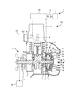
- FIG. 1 is an external view showing a vehicle according to an embodiment of the present invention. It is a fragmentary sectional view which shows typically the schematic structure of the engine unit shown in FIG. It is sectional drawing which shows a cross section perpendicular
- FIG. 1 is an external view showing a vehicle according to an embodiment of the present invention.
- a vehicle 1 shown in FIG. 1 is a vehicle with wheels.
- the vehicle 1 includes a vehicle body 2 and wheels 3a and 3b.
- the vehicle 1 is a saddle type vehicle.
- the vehicle 1 is a motorcycle.
- the vehicle 1 includes an engine unit EU.
- the engine unit EU includes an engine 10 and a starter generator 20 (see FIG. 2). That is, the vehicle 1 includes an engine 10 and a starter generator 20.
- the rear wheel 3b receives the rotational power output from the engine 10 to drive the vehicle 1.
- the wheel 3b corresponds to an example of a drive member according to the present invention.
- the vehicle 1 includes a main switch 5.
- the main switch 5 is a switch for supplying power to each part of the vehicle 1.
- the vehicle 1 includes a starter switch 6.
- the starter switch 6 is a switch for starting the engine 10.
- the vehicle 1 includes an accelerator operation element 8.
- the accelerator operation element 8 is an operation element for instructing acceleration of the vehicle 1.
- the vehicle 1 includes a headlamp 7.
- the vehicle 1 includes a power storage 4 that stores power.
- the vehicle 1 includes a control device 60 that controls each part of the vehicle 1.
- FIG. 2 is a partial cross-sectional view schematically showing a schematic configuration of the engine unit EU shown in FIG.
- the engine 10 includes a crankcase 11, a cylinder 12, a piston 13, a connecting rod 14, and a crankshaft 15.
- the piston 13 is provided in the cylinder 12 so as to be reciprocally movable.
- the crankshaft 15 is rotatably provided in the crankcase 11.
- the connecting rod 14 connects the piston 13 and the crankshaft 15.
- a cylinder head 16 is attached to the upper portion of the cylinder 12.
- a combustion chamber is formed by the cylinder 12, the cylinder head 16, and the piston 13.
- the crankshaft 15 is supported on the crankcase 11 via a pair of bearings 17 in a rotatable manner.
- a starter / generator 20 is attached to one end 15 a of the crankshaft 15.
- a continuously variable transmission CVT is attached to the other end 15 b of the crankshaft 15.
- Wheel 3b receives rotational power output from engine 10 via crankshaft 15, continuously variable transmission CVT, and a clutch (not shown).
- the engine 10 is provided with a throttle valve SV and a fuel injection device 18.
- the throttle valve SV adjusts the amount of air supplied to the combustion chamber.
- the opening degree of the throttle valve SV is adjusted according to the operation of the accelerator operator 8 (see FIG. 1).
- the fuel injection device 18 supplies fuel to the combustion chamber by injecting fuel.
- the engine 10 is provided with a spark plug 19.
- the engine 10 is an internal combustion engine.
- the engine 10 is supplied with fuel.
- the engine 10 outputs rotational power by a combustion operation for burning fuel.
- the fuel injection device 18 adjusts the rotational power output from the engine 10 by adjusting the amount of fuel supplied.
- the fuel injection device 18 functions as a rotational power adjustment device that adjusts the rotational power output from the engine 10.
- the engine 10 outputs rotational power via the crankshaft 15.
- the rotational power of the crankshaft 15 is transmitted to the wheel 3b via the continuously variable transmission CVT and a clutch (not shown).
- the vehicle 1 is driven by wheels 3 b that receive rotational power output from the engine 10 via the crankshaft 15.
- the engine 10 of this embodiment is a single-cylinder four-stroke engine.
- the engine 10 of this embodiment is an air-cooled engine.
- the engine 10 may be a water-cooled engine.
- the engine 10 has a high load region where the load for rotating the crankshaft 15 is large and a low load region where the load for rotating the crankshaft 15 is smaller than the load in the high load region during four strokes. Looking at the rotation angle of the crankshaft 15 as a reference, the low load region is wider than the high load region. More specifically, the engine 10 rotates forward while repeating four strokes of an intake stroke, a compression stroke, an expansion stroke, and an exhaust stroke. The compression stroke is included in the high load region and is not included in the low load region.
- FIG. 3 is a cross-sectional view showing a cross section perpendicular to the rotation axis of the starting generator 20 shown in FIG.
- the starter / generator 20 will be described with reference to FIGS. 2 and 3.
- the starting generator 20 is a permanent magnet type three-phase brushless motor.
- the starter generator 20 also functions as a permanent magnet type three-phase brushless generator.
- the starter generator 20 includes a rotor 30 and a stator 40.
- the starter generator 20 of the present embodiment is a radial gap type.
- the starter generator 20 is an outer rotor type. That is, the rotor 30 is an outer rotor.
- the stator 40 is an inner stator.
- the rotor 30 has a rotor main body 31.
- the rotor main body 31 is made of, for example, a ferromagnetic material.
- the rotor main body 31 has a bottomed cylindrical shape.
- the rotor main body 31 includes a cylindrical boss portion 32, a disk-shaped bottom wall portion 33, and a cylindrical back yoke portion 34.
- the bottom wall portion 33 and the back yoke portion 34 are integrally formed.
- the bottom wall portion 33 and the back yoke portion 34 may be configured separately.
- the bottom wall portion 33 and the back yoke portion 34 are fixed to the crankshaft 15 via the cylindrical boss portion 32.
- the rotor 30 is not provided with a winding to which current is supplied.
- the rotor 30 has a permanent magnet part 37.
- the rotor 30 has a plurality of magnetic pole portions 37a.
- the plurality of magnetic pole portions 37 a are formed by permanent magnet portions 37.
- the plurality of magnetic pole portions 37 a are provided on the inner peripheral surface of the back yoke portion 34.
- the permanent magnet portion 37 has a plurality of permanent magnets.
- the plurality of magnetic pole portions 37a are provided in each of the plurality of permanent magnets.
- the permanent magnet part 37 can also be formed by one annular permanent magnet. In this case, one permanent magnet is magnetized such that a plurality of magnetic pole portions 37a are arranged on the inner peripheral surface.
- the plurality of magnetic pole portions 37 a are provided so that N poles and S poles are alternately arranged in the circumferential direction of the starting generator 20.
- the number of magnetic poles of the rotor 30 facing the stator 40 is 24.
- the number of magnetic poles of the rotor 30 refers to the number of magnetic poles facing the stator 40.
- No magnetic material is provided between the magnetic pole part 37a and the stator 40.
- the magnetic pole portion 37 a is provided outside the stator 40 in the radial direction of the starting generator 20.
- the back yoke portion 34 is provided outside the magnetic pole portion 37a in the radial direction.
- the starter generator 20 has more magnetic pole portions 37 a than the number of tooth portions 43.
- the rotor 30 may be an embedded magnet type (IPM type) in which the magnetic pole portion 37a is embedded in a magnetic material.
- IPM type embedded magnet type
- SPM type surface magnet type in which the magnetic pole portion 37a is exposed from the magnetic material.
- the cooling fan F is provided in the bottom wall part 33 which comprises the rotor 30.
- the stator 40 has a stator core ST and a plurality of stator windings W.
- Stator core ST has a plurality of teeth 43 provided at intervals in the circumferential direction.
- the plurality of tooth portions 43 integrally extend from the stator core ST toward the radially outer side.
- a total of 18 tooth portions 43 are provided at intervals in the circumferential direction.
- the stator core ST has a total of 18 slots SL formed at intervals in the circumferential direction.
- the tooth portions 43 are arranged at equal intervals in the circumferential direction.
- the rotor 30 has more magnetic pole portions 37 a than the number of tooth portions 43.
- the number of magnetic pole portions is 4/3 of the number of slots.
- a stator winding W is wound around each tooth portion 43. That is, the multiple-phase stator winding W is provided so as to pass through the slot SL.
- FIG. 3 shows a state in which the stator winding W is in the slot SL.
- Each of the multi-phase stator windings W belongs to one of the U phase, the V phase, and the W phase.
- the stator windings W are arranged in the order of the U phase, the V phase, and the W phase.
- the winding method of the stator winding W may be concentrated winding or distributed winding, and is not particularly limited, but concentrated winding is preferable.
- a plurality of detected portions 38 for detecting the rotational position of the rotor 30 are provided on the outer surface of the rotor 30.
- the plurality of detected parts 38 are detected by a magnetic action.
- the plurality of detected portions 38 are provided on the outer surface of the rotor 30 at intervals in the circumferential direction.
- the detected portion 38 is made of a ferromagnetic material.
- the rotor position detection device 50 is a device that detects the position of the rotor 30.
- the rotor position detection device 50 is provided at a position facing the plurality of detected parts 38.
- the starter generator 20 is connected to the crankshaft 15 of the engine 10.
- the rotor 30 is connected to the crankshaft 15 so as to rotate at a fixed speed ratio with respect to the crankshaft 15.
- the rotor 30 is attached to the crankshaft 15 without a power transmission mechanism (for example, a belt, a chain, a gear, a speed reducer, a speed increaser, etc.).
- the rotor 30 rotates with respect to the crankshaft 15 at a speed ratio of 1: 1.
- the starter / generator 20 is configured to rotate the crankshaft 15 in the forward direction by the forward rotation of the engine 10.
- the starter generator 20 may be attached to the crankshaft 15 via a power transmission mechanism.
- the starter generator 20 is connected to the crankshaft 15 without any speed variable transmission or clutch. That is, the starter / generator 20 is connected to the crankshaft 15 without a device having a variable input / output speed ratio.
- the starter generator 20 is attached to the crankshaft 15 without using a power transmission mechanism as in the present embodiment.
- the starter generator 20 starts the engine 10 by rotating the crankshaft 15 forward when the engine is started.
- the starter generator 20 is driven by the engine 10 to generate power when the engine 10 performs a combustion operation. That is, the starter / generator 20 has both a function of starting the engine 10 by rotating the crankshaft 15 forward and a function of generating power by being driven by the engine 10 when the engine 10 performs a combustion operation.
- the starter / generator 20 is rotated forward by the crankshaft 15 and functions as a generator during at least a part of the period after the engine 10 is started. That is, when the starter / generator 20 functions as a generator, the starter / generator 20 does not always need to function as a generator after the start of combustion of the engine.
- the starter / generator 20 functions as a generator and a period in which the starter / generator 20 functions as a vehicle drive motor may be included.
- the member that transmits the rotational power from the engine to the wheel 3b is provided with only the starter generator 20 as a device that performs conversion between the rotational power and the power related to the driving of the wheel 3b.
- the vehicle of the present invention is not limited to this, and a device other than the starter generator that performs conversion between rotational power and electric power may be connected to a member that transmits rotational power from the engine to the driving member. .
- the starter / generator 20 starts the engine 10 by rotating the crankshaft 15 forward when the engine is started.
- the starter / generator 20 rotates the crankshaft 15 in a forward direction in a state where the combustion operation of the engine 10 is stopped after the engine 10 is started.
- it is advantageous that the starter / generator 20 has a larger outputable torque.
- the crankshaft 15 having a larger load can be rotated forward.
- the ability to exceed the load in the high load region when the engine is started is high.
- the starter generator functions as a generator, if the output torque of the starter generator is improved, the generated current of the starter generator may increase.
- the output torque which can be output increases also by making comparatively wide the space
- the generated current of the starter generator becomes large when the starter generator is driven by the engine.
- the charging current to the power storage connected to the starter generator may become excessive.
- the current generated in the starter generator is converted into heat by controlling the inverter. When current is converted to heat and discarded, fuel loss increases.
- the starter generator 20 of the present embodiment has more magnetic pole portions 37 a than the number of tooth portions 43. For this reason, the starter generator 20 has a higher angular velocity than a starter generator having fewer magnetic poles than the number of teeth.
- Angular velocity contributes to the winding impedance. That is, the winding impedance is roughly expressed by the following equation. (R 2 + ⁇ 2 L 2 ) 1/2 Where R: DC resistance, ⁇ : angular velocity with respect to electrical angle, L: inductance
- ⁇ (P / 2) ⁇ (N / 60) ⁇ 2 ⁇
- P number of magnetic poles
- N rotational speed [rpm]
- the starter generator 20 Since the starter generator 20 has more magnetic pole portions 37a than the number of teeth 43, the angular velocity ⁇ is higher than that of a starter generator having fewer magnetic poles than the number of teeth. Therefore, the impedance when rotating is large. In addition, as the rotational speed N increases, the angular speed ⁇ increases and the impedance increases. Therefore, the starter / generator 20 can suppress a generated current by ensuring a large impedance in a rotation region used as a generator.
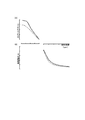
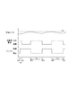
- FIG. 4A is an explanatory diagram schematically showing the drive characteristics of the starter generator 20.
- FIG. 4B is an explanatory diagram schematically showing power generation characteristics.
- the horizontal axis indicates the rotational speed of the crankshaft 15. Note that the rotational speed per scale on the horizontal axis is different between FIG. 4A of the drive characteristics and FIG. 4B of the power generation characteristics.
- the rotational speed per scale in the power generation characteristic diagram is greater than the rotational speed per scale in the drive characteristic diagram.
- the vertical axis shows the output torque in the positive direction and the generated current in the negative direction.
- a solid line indicates the characteristics of the starter generator 20 according to the embodiment.
- a broken line shows the characteristic of the starter generator concerning a comparative example.
- the starter generator according to the comparative example has fewer magnetic pole portions than the number of tooth portions.
- the starter generator 20 of the present embodiment is designed with priority on torque improvement among torque improvement and generation current suppression.
- the torque improvement can be prioritized by ensuring a relatively wide space between the tip portions of the adjacent tooth portions 43 facing the rotor 30.
- the starter generator 20 (solid line) of the present embodiment outputs a torque larger than that of the starter generator (broken line) according to the comparative example (FIG. 4A), and at high speed rotation
- the generated current can be suppressed to the same extent as the starter generator (broken line) according to the comparative example (FIG. 4B).
- FIG. 5 is a block diagram showing a schematic electrical configuration of the vehicle 1 shown in FIG.
- the vehicle 1 includes a control device 60.
- the control device 60 controls each part of the vehicle 1.
- the control device 60 includes an inverter 61.
- the starter generator 20 and the power storage 4 are connected to the inverter 61.
- the power storage 4 exchanges current with the starter generator 20.
- a headlamp 7 is also connected to the inverter 61 and the power storage 4.
- the headlamp 7 is an example of an auxiliary machine mounted on the vehicle 1 that operates while consuming electric power.
- the inverter 61 includes a plurality of switching units 611 to 616.
- the inverter 61 of the present embodiment includes six switching units 611 to 616.
- the switching units 611 to 616 constitute a three-phase bridge inverter.
- the plurality of switching units 611 to 616 are connected to each phase of the stator winding W having a plurality of phases. More specifically, of the plurality of switching units 611 to 616, two switching units connected in series constitute a half bridge.
- the inverter 61 has a half bridge corresponding to each phase of the multi-phase stator winding W.
- the plurality of half bridges are connected to the respective phases of the plurality of phases of the stator winding W. Switching units 611 to 616 switch current passing / cutting between the plurality of phases of stator winding W and power storage 4.
- the starter generator 20 functions as a starter generator
- energization and deenergization of each of the stator windings W of the plurality of phases are switched by on / off operations of the switching units 611 to 616.
- the on / off operation of the switching units 611 to 616 switches between current passing / breaking between each of the stator windings W and the power storage 4.
- Each of the switching units 611 to 616 has a switching element.
- the switching element is, for example, a transistor, and more specifically, an FET (Field Effect Transistor).
- FET Field Effect Transistor
- thyristors and IGBTs Insulated Gate Bipolar Transistors
- a fuel injection device 18, a spark plug 19, and a power storage 4 are connected to the control device 60.
- the control device 60 includes a starting power generation control unit 62 and a combustion control unit 63.
- the starting power generation control unit 62 controls the operation of the starting generator 20 by controlling the on / off operations of the switching units 611 to 616.
- the start power generation control unit 62 includes a start control unit 621, a travel control unit 622, and an idling control unit 623.
- the combustion control unit 63 controls the combustion operation of the engine 10 by controlling the spark plug 19 and the fuel injection device 18.
- the combustion control unit 63 controls the rotational power of the engine 10.
- the control device 60 is composed of a computer having a central processing unit (not shown) and a storage device (not shown).
- the central processing unit performs arithmetic processing based on the control program.
- the storage device stores data relating to programs and operations.
- the startup power generation control unit 62 including the start control unit 621, the travel control unit 622, and the idling control unit 623, and the combustion control unit 63 are realized by a computer (not shown) and a control program executed by the computer. Therefore, the operations of the starting power generation control unit 62 including the start control unit 621, the travel control unit 622, and the idling control unit 623, and the combustion control unit 63, which will be described later, can be said to be operations of the control device 60. it can.
- the starting power generation control unit 62 and the combustion control unit 63 may be configured as separate devices, for example, at positions separated from each other, or may be configured integrally.
- a starter switch 6 is connected to the control device 60.
- the starter switch 6 is operated by the driver when the engine 10 is started.
- the starting power generation control unit 62 of the control device 60 detects the charge level of the power storage 4.
- the starting power generation control unit 62 detects the charge level of the power storage 4 by detecting the voltage and current of the power storage 4.
- a vehicle speed sensor 66 that detects the vehicle speed of the vehicle 1 is connected to the control device 60.
- the control device 60 acquires the vehicle speed of the vehicle 1 based on the result of the vehicle speed sensor 66.
- the starting power generation control unit 62 detects the opening of the throttle valve SV (see FIG. 2) based on the detection result of a throttle sensor (not shown).
- the starting power generation control unit 62 detects the temperature of the engine oil in the engine 10 based on the detection result of a temperature sensor (not shown).
- the main switch 5 receives an instruction related to power supply to the control device 60 according to an operation. When the main switch 5 is turned on, power is supplied to the control device 60. When the main switch 5 is turned off, the power supply to the control device 60 is stopped. The main switch 5 is turned on / off to supply power to the electrical equipment such as auxiliary equipment of the headlamp 7 and to stop the power supply.
- the inverter 61, the starting power generation control unit 62, and the combustion control unit 63 of the control device 60 control the engine 10 and the starting generator 20.
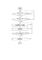
- FIG. 6 is a flowchart for explaining the operation of the vehicle 1. The operation of the vehicle 1 will be described with reference to FIGS.
- the control device 60 determines whether or not the main switch 5 is on (S11). When the main switch 5 is in the on state (Yes in S11), the control device 60 determines whether or not the starter switch 6 is in the on state (S12).
- the control device 60 starts the engine 10. Specifically, the start control unit 621 of the start power generation control unit 62 starts the engine 10. Specifically, the start control unit 621 causes the starter generator 20 to drive the crankshaft 15 (S13). The start control unit 621 performs on / off operations of the plurality of switching units 611 to 616 included in the inverter 61 so that a current that causes the rotor 30 to rotate forward is supplied to the plurality of stator windings W. As a result, the starter / generator 20 drives the crankshaft 15. Further, the combustion control unit 63 of the control device 60 causes the fuel injection device 18 to supply fuel (S14).
- step S14 the combustion control unit 63 causes the spark plug 19 to ignite.
- the start control unit 621 determines whether or not the engine 10 has been started (S15). When the start of the engine 10 is not completed (No in S15), the start control unit 621 and the combustion control unit 63 continue rotation of the crankshaft 15 (S13) and fuel supply (S14) by the starter generator 20. The combustion control unit 63 continues to supply fuel until the driving state is switched even after the start of the engine 10 is completed.
- the start control unit 621 determines completion of starting of the engine 10 based on, for example, the rotational speed of the crankshaft 15. For example, the start control unit 621 acquires the rotational speed of the crankshaft 15 from the detection result of the rotor position detection device 50.
- the state in which the start of the engine 10 is completed is a state in which the control device 60 causes the engine 10 to perform a combustion operation in a state where electric power is supplied from the main switch 5.
- the control device 60 performs an operation process after the start (S16).
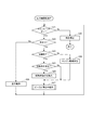
- FIG. 7 is a flowchart for explaining the operation after the vehicle starts.
- the control device 60 determines whether or not the main switch 5 is on (S21). When the main switch 5 is in the off state (No in S21), the control device 60 stops the operation of the engine 10 (S22). Thereafter, the control device 60 ends the processing of the operation after starting. In step S22, the control device 60 stops both the combustion operation of the engine 10 and the driving by the starter generator 20. Specifically, when the main switch 5 is in an off state (Yes in S21), the control device 60 stops the fuel supply by the fuel injection device 18. Further, the control device 60 does not drive the crankshaft 15 by the starter generator 20.
- the control device 60 determines whether or not the vehicle speed, that is, the traveling speed of the vehicle 1 is zero (S23). When the vehicle speed is not zero (No in S23), the vehicle 1 is traveling. When the vehicle speed is not zero (No in S23), the control device 60 performs a traveling operation (S28). Specifically, the travel control unit 622 of the start power generation control unit 62 performs a travel operation (S28). In the traveling operation of step S28, the traveling control unit 622 controls the engine 10 for causing the vehicle 1 to travel. For example, the travel control unit 622 causes the fuel injection device 18 to adjust the amount of fuel supplied according to the opening of the throttle valve SV.
- control device 60 controls the fuel injection device 18 as a rotational power adjustment unit. As a result, the engine 10 outputs rotational power corresponding to the driver's operation. In the traveling operation in step S28, the control device 60 causes the starter generator 20 to generate power. The electric power generated by the starter generator 20 is charged in the electric power storage 4.
- the state where the vehicle speed is zero is a state where the on state of the main switch 5 continues and the vehicle 1 is stopped. In this state, transmission of rotational power from the crankshaft 15 to the wheel 3b is stopped.
- the control device 60 performs idling control. More specifically, the idling control unit 623 and the combustion control unit 63 of the starting power generation control unit 62 perform idling control.
- the idling control unit 623 determines whether or not the warm-up operation of the engine 10 has been completed (S24).
- step S24 If it is determined in step S24 that the warm-up has not been completed (No in S24), the idling control unit 623 of the control device 60 sets the engine drive state as the drive state (S29).
- the engine driving state is a combustion operation of the engine 10. As the engine 10 performs the combustion operation, the temperature of the engine 10 rises higher than the temperature before the engine 10 is started. Details of the engine drive state will be described later.
- step S24 the control device 60 of the present embodiment determines whether or not the temperature of the engine 10 has exceeded a predetermined switching permission temperature.
- the switching permission temperature is a warm-up completion temperature that is predetermined for the engine that indicates a state in which the warm-up of the engine 10 is completed.
- the temperature of the engine 10 for example, the temperature of the engine oil is used. In the case where the engine 10 is a water-cooled engine, a water temperature may be used as the temperature of the engine 10.
- the temperature of the engine 10 is low, the load on the rotation of the crankshaft 15 is large due to the viscosity of the engine oil and the like.
- control device 60 repeatedly switches the state of the crankshaft during a part of a period in which the temperature of the engine exceeds a switching permission temperature as a warm-up completion temperature predetermined for the engine. At this time, the load when the starter / generator 20 rotates the crankshaft 15 is reduced.
- the idling control unit 623 determines whether a switching condition is satisfied (S25).
- the switching condition is a condition for switching the driving state of the engine 10 and the starting generator 20.
- the idling control unit 623 switches the driving state of the engine 10 and the starter generator 20 while the vehicle 1 is stopped (S26).
- the control device 60 has a plurality of states as drive states of the engine 10 and the starter generator 20 when the vehicle is stopped.
- the plurality of states include an engine drive state and a starter generator drive state.
- the engine driving state is a state in which the crankshaft 15 is rotated forward by causing the engine 10 to perform a combustion operation.
- the starter generator drive state is a state in which the crankshaft 15 is rotated forward by causing the starter generator 20 to drive the crankshaft 15 while stopping the combustion operation of the engine 10.
- the switching condition in step S25 of the present embodiment is the charge level (SOC) of the power storage 4. That is, the idling control unit 623 switches the driving state of the engine 10 and the starter generator 20 in step S ⁇ b> 26 according to the charge level of the power storage 4.
- the idling control unit 623 acquires the charge level of the power storage 4.
- the idling control unit 623 acquires the charge level using at least one of the voltage of the power storage 4 and the current of the power storage 4.
- the idling control unit 623 of the present embodiment acquires the charge level of the power storage 4 according to the voltage of the power storage 4.
- the voltage of the power storage 4 is higher as the charge level of the power storage 4 is higher.
- the configuration for acquiring the charge level is simplified by the voltage of the power storage 4.
- the idling control unit 623 determines that the switching condition is satisfied when the charge level of the power storage 4 exceeds the upper limit of a predetermined range (Yes in S25).
- the upper limit of the predetermined range is, for example, a predetermined charge level of the fully charged state of the power storage 4.
- the predetermined fully charged state of the power storage 4 is a state in which an amount of power close to the rated charge amount of the power storage 4 is charged.
- the fully charged state is, for example, a state where power in a range of +/ ⁇ 10% with respect to the rated charge amount of the power storage 4 is charged.
- step S26 the control device 60 switches the state of the crankshaft 15, that is, the driving state of the crankshaft 15 by the engine 10 and the starting generator 20 to the starting generator driving state.
- the idling control unit 623 switches the control state of the crankshaft 15 to the starter generator drive state.
- the idling control unit 623 of the present embodiment switches the control state of the crankshaft 15 to the starter generator drive state when the charge level of the power storage 4 exceeds the upper limit of a predetermined range.
- the idling control unit 623 switches the control state of the crankshaft 15 to the starter generator drive state when the power storage 4 is in a fully charged state.
- the power storage 4 tends to maintain a fully charged state or a high charge level close to full charge. More specifically, the idling control unit 623 switches the control state of the crankshaft 15 to the starter generator drive state when the voltage of the power storage 4 is a voltage corresponding to the fully charged state. In later step S27, an operation corresponding to the switched state is performed. The idling control unit 623 switches the state of the crankshaft 15 from the engine drive state to the starter generator drive state so as to reduce the charge level of the power storage 4. The idling control unit 623 switches the state of the crankshaft 15 from the starter generator drive state to the engine drive state so as to increase the charge level of the power storage 4.
- the idling control unit 623 determines that the switching condition is satisfied when the charge level of the power storage 4 falls below the lower limit of the above range (Yes in S25). In this case, in step S26, the idling control unit 623 switches the state of the crankshaft 15, that is, the driving state of the crankshaft 15 by the engine 10 and the starter generator 20, to the engine driving state. Specifically, the idling control unit 623 switches the control state of the crankshaft 15 to the engine drive state.
- the lower limit of the predetermined range is, for example, lower than a predetermined charge level of the power storage 4 in the fully charged state. Power storage
- the idling control unit 623 After the switching in step S26, the idling control unit 623 performs an operation while the vehicle is stopped (S27). The idling control unit 623 operates the engine 10 and the starter generator 20 in accordance with the state switched in step S26.
- step S25 when the switching condition is not satisfied (No in S25), the idling control unit 623 does not switch the state of the crankshaft 15. Therefore, the driving state of the crankshaft 15 by the engine 10 and the starter / generator 20 is continued.
- FIG. 8 is a flowchart for explaining the operation while the vehicle is stopped.
- the idling control unit 623 determines the drive state set in step S26 (S31).
- step S31 when it is determined that the drive state of the crankshaft 15 by the engine 10 and the starter generator 20 is the starter generator drive state, the control device 60 stops the combustion operation of the engine 10 (S32).
- the combustion control unit 63 of the control device 60 stops the fuel supply by the fuel injection device 18. That is, the control device 60 causes the fuel injection device 18 as the rotational power adjustment unit to stop outputting rotational power from the engine 10.
- the idling control unit 623 causes the starter / generator 20 to drive the crankshaft 15 to cause the crankshaft 15 to rotate forward (S33).
- the engine 10 is driven by the starter generator 20.
- the combustion control unit 63 causes the engine 10 to perform a combustion operation to rotate the crankshaft 15 forward. (S34). Further, the idling control unit 623 causes the starter generator 20 to generate power (S35).
- the starter generator 20 is driven by the engine 10.
- step S ⁇ b> 32 the control device 60 causes the starter generator 20 to drive the crankshaft 15. More specifically, the idling control unit 623 performs a plurality of switching operations of the inverter 61 according to the rotational position of the rotor 30 so that a current that causes the rotor 30 to rotate in the forward direction is supplied to the stator windings W of the plurality of phases.
- the units 611 to 616 are turned on / off.
- the starter generator 20 enters a power running state.
- the starter / generator 20 drives the crankshaft 15.
- an on / off operation of the switching units 611 to 616 an operation by a 120-degree energization method is performed.
- the 120-degree energization method is a method in which an energization stop period is provided for each phase of the stator winding W having a plurality of phases and intermittent energization is performed with an energization angle of less than 180 degrees.
- the stator winding W of each phase is energized for a period of 120 degrees in electrical angle.
- the energization stop period arrives at each phase of the stator winding W of a plurality of phases in order.
- the idling control unit 623 controls two states of current supply (energization) and non-supply (non-energization).
- the electrical angle is an angle based on the repetition period of the magnetic poles.
- the idling control unit 623 may turn on the switching units 611 to 616 with a PWM-modulated signal.
- the idling control unit 623 may perform vector control of the starter generator 20.
- Vector control is a method of controlling the current supplied to the starter generator 20 by separating it into a d-axis component corresponding to the magnetic flux direction of the magnet and a q-axis component perpendicular to the magnetic flux direction in electrical angle.
- the q-axis component is a component that affects the torque load of the starting generator 20.
- the vector control is a control for energizing each phase of the plurality of phases of the stator winding W without energization pause.
- the vector control is a control in which energization is performed so that a sine wave current flows in each phase of the stator winding W of a plurality of phases.
- a sine wave current flows in each of the plurality of stator windings W.
- Power generation by vector control is realized, for example, by drawing a current in the direction of the induced electromotive voltage so as to synchronize with the sine wave of the induced electromotive voltage of the stator winding W.
- the sine wave current and the sine wave voltage mean a sine wave current and voltage.
- the sine wave current includes, for example, ripple and distortion associated with the on / off operation of the switching unit.
- each of the plurality of switching units 611 to 616 is controlled by a signal subjected to pulse width modulation (PWM).
- PWM pulse width modulation
- the period of the pulse in the pulse width modulation is shorter than the period of the induced electromotive voltage of each phase of the stator winding W. That is, the idling control unit 623 controls on / off of the plurality of switching units 611 to 616 in accordance with a pulse signal having a cycle shorter than the cycle of the induced electromotive voltage of the stator winding W of the starting generator 20.
- the idling control unit 623 calculates the d-axis component and the q-axis component from the currents of the stator windings W of a plurality of phases detected by a sensor (not shown) and the position of the rotor 30 detected by the rotor position detection device 50. obtain.
- the idling control unit 623 controls the on / off timing of the plurality of switching units 611 to 616 so that the d-axis component and the q-axis component approach the predetermined target value.
- step S32 the idling control unit 623 performs phase control.
- the phase control is a control different from the vector control described above.
- the idling control unit 623 causes each of the plurality of switching units 611 to 616 to perform an on / off operation at a period equal to the period of the induced electromotive voltage of the stator winding W.
- the idling control unit 623 turns each of the plurality of switching units 611 to 616 on and off based on the position of the rotor 30 detected by the rotor position detection device 50. Note that the idling control unit 623 may perform vector control instead of phase control in step S32.
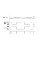
- FIG. 9 is a time chart showing the transition of the driving state of the engine 10 and the starting generator 20.
- the driving state of the crankshaft 15 by the engine 10 and the starter / generator 20 will be described with reference to the flowcharts of FIGS. 6 to 8 and FIG.
- the horizontal axis of the time chart indicates the passage of time, and the vertical axis indicates the state of the starter generator 20 and the state of the engine 10.
- the charge level of the power storage 4 is shown.
- the upper limit La and the lower limit Lb of the range of the charge level which are the driving state switching conditions, are shown.
- the starter generator 20 is in a power running state.
- the starter / generator 20 drives the crankshaft 15.
- the starter / generator 20 rotates the crankshaft 15 forward.
- the charge level of the power storage 4 decreases.
- the control device 60 stops driving the crankshaft 15 by the starter generator 20.
- the control device 60 causes the engine 10 to perform a combustion operation.
- the crankshaft 15 is driven by the engine 10.
- the starter generator 20 generates power.
- the charge level of the power storage 4 increases.
- the control device 60 switches the driving state (S26).
- the switching condition is established when the charge level of the power storage 4 exceeds the upper limit La of a predetermined range.
- the driving state of the crankshaft 15 by the engine 10 and the starting generator 20 is switched to the starting generator driving state. That is, the combustion operation of the engine 10 is stopped (S32).
- the starter / generator 20 drives the crankshaft 15 (S33). In the starter generator driving state, the combustion operation of the engine 10 is stopped, so that fuel consumption is suppressed. That is, fuel efficiency is improved.
- the warming-up is completed (Yes in S24), and the driving conditions are switched. That is, when the temperature of the engine 10 exceeds the switching permission temperature, the combustion operation of the engine 10 is stopped and the starter generator 20 drives the crankshaft 15. Since the temperature of the engine 10 is high at this time, the load when the starter / generator 20 drives the crankshaft 15 is reduced.
- the control device 60 switches the driving state (S26).
- the switching condition is satisfied when the charge level of the power storage 4 falls below the lower limit Lb of the predetermined range.
- the driving state of the crankshaft 15 by the engine 10 and the starter / generator 20 is switched to the engine driving state. That is, the engine 10 burns to drive the crankshaft 15 (S34).
- the starting generator 20 generates power (S35).
- the starter generator 20 driven by the crankshaft 15 generates power and supplies power to the power storage 4. Since the power storage 4 can be charged, the power storage 4 is charged.
- the rotational speed of the crankshaft 15 is reduced by the rotational load of the starter / generator 20 that charges the power storage 4 as compared to the case where the starter / generator 20 is not charged. Accordingly, the number of fuel injections is reduced. For this reason, fuel efficiency improves.
- the crankshaft 15 Before the driving state is switched to the engine driving state at time t5, the crankshaft 15 is driven by the starter / generator 20 and is rotating forward. If fuel is supplied to the engine 10, the combustion operation of the engine 10 is resumed. That is, it is not necessary to drive the crankshaft 15 from the stopped state. For this reason, the electric power consumed by state switching is suppressed. That is, the electric power consumed to make the engine 10 burn again is suppressed.
- the combustion operation of the engine can be resumed with less power storage power than when the crankshaft is driven from a stopped state.
- the occurrence of a situation where it is difficult to restart the combustion operation of the engine 10 is suppressed. Therefore, the occurrence of a situation where the charge level of the power storage is excessively reduced can be suppressed.
- the starter generator 20 When the combustion operation of the engine 10 resumes, the starter generator 20 generates power. The starter generator 20 charges the power storage. Accordingly, the charge level of the power storage is restored.
- the control device 60 switches the driving state of the crankshaft 15 by the engine 10 and the starter / generator 20 (S26).
- the switching condition is satisfied when the charge level of the power storage 4 exceeds the upper limit of a predetermined range.
- the driving state of the crankshaft 15 by the engine 10 and the starting generator 20 is switched to the starting generator driving state. That is, the combustion operation of the engine 10 is stopped (S32).
- the starter / generator 20 drives the crankshaft 15 (S33).
- the control device 60 switches the driving state (S26).
- the switching condition is established when the charge level of the power storage 4 falls below the lower limit of a predetermined range.
- the driving state of the crankshaft 15 by the engine 10 and the starter / generator 20 is switched to the engine driving state. That is, the engine 10 burns to drive the crankshaft 15 (S34).
- the starting generator 20 generates power (S35).
- a plurality of states including the engine drive state are repeatedly switched. In the engine driving state, the power storage 4 is charged. Accordingly, the power storage 4 is repeatedly charged.
- the operation can be continued while a plurality of states including the engine drive state and the starter generator drive state are repeatedly switched. In at least a part of the period, the state of the crankshaft 15 is switched from one of the engine drive state and the starter generator drive state to the other state. Thereby, the forward rotation of the crankshaft 15 is continued.
- fuel efficiency can be improved while suppressing the occurrence of a situation where the charge level of the power storage 4 is excessively lowered for a long time.
- the electric power storage 4 can be reduced in size.
- the engine drive state and the starter generator drive state are switched alternately. For this reason, the starter generator drive state is implemented following the engine drive state. According to the present embodiment, the occurrence of a situation where the charge level of the power storage 4 is lowered is further suppressed.
- the rotation of the crankshaft continues, for example, unpleasant vibration that may occur when the crankshaft is restarted from a stopped state can be suppressed.
- the state of switching includes a stopped state of the crankshaft
- the combustion operation of the engine starts from the stopped state of the crankshaft.
- the rotational force may be transmitted to the wheels via the transmission and the clutch.
- vibration may occur in the vehicle body or the wheel.
- the restart is performed regardless of the driver's operation. Therefore, the vibration accompanying the restart may be an unpleasant vibration unexpected for the driver.
- the engine drive state and the starter generator drive state are alternately switched, a situation in which the stopped crankshaft starts rotating can be suppressed regardless of the operation of the driver. Therefore, vibration unpleasant for the driver can be suppressed.
- the starter generator 20 has a larger number of magnetic pole portions 37 a than the number of the tooth portions 43. For this reason, even if the torque for forward rotation of the crankshaft 15 increases, for example, the generated current during high-speed rotation of the crankshaft 15 such as when the vehicle 1 is traveling is suppressed. For this reason, the electric current consumed as heat is suppressed. Accordingly, the fuel efficiency of the vehicle 1 is further improved.
- the switching condition is the arrival of a predetermined time period. That is, in the present embodiment, the control device 60 switches the drive state of the crankshaft 15 by the engine 10 and the starter generator 20 at a predetermined time period (S26). Specifically, the control device 60 sets the drive state of the crankshaft 15 by the engine 10 and the starter generator 20 in a plurality of states including a starter generator drive state and an engine drive state in a predetermined time period. Switch repeatedly between. More specifically, the control device 60 in the present embodiment alternately switches the state of the crankshaft 15 between the starter generator drive state and the engine drive state at a predetermined time period.
- the control device 60 switches the drive state so that the time cycle of the starter generator drive state is different from the time cycle of the engine drive state.
- the time cycle of the starting generator driving state is the time period from the timing when the driving state is switched from the engine driving state to the starting generator driving state until the timing when the driving state is switched from the starting generator driving state to the engine driving state.
- the time period of the engine driving state is a time period from the timing when the driving state is switched from the starting generator driving state to the engine driving state until the timing when the driving state is switched from the engine driving state to the starting generator driving state.
- the control device 60 determines the drive state of the crankshaft 15 so that the ratio between the time cycle of the starter generator drive state and the time cycle of the engine drive state is such that the average charge level of the power storage 4 does not decrease.
- Switch In other words, the control device 60 drives the crankshaft 15 so that the amount of decrease in the charge level of the power storage 4 during the starter generator drive state does not exceed the amount of increase in the charge level during the engine drive state.
- Switch state The ratio between the time cycle of the starter generator drive state and the time cycle of the engine drive state is set so that the average of the charge level of the power storage 4 in the time cycle of both the starter generator drive state and the engine drive state does not decrease.
- the time period of the starter generator driving state is set so that the charge level of the power storage 4 does not fall below a level at which the rotation speed of the crankshaft 15 that can restart the combustion operation of the engine 10 is maintained. That is, the time period of the starter generator driving state is set such that a decrease in the charge level of the power storage 4 due to the starter generator driving state can be suppressed to such an extent that the combustion operation of the engine 10 can be resumed. This facilitates restarting the combustion operation of the engine 10.
- the charging of the power storage 4 and the combustion operation of the engine 10 occur according to the time period.
- the starter generator drive state and the engine drive state are periodically implemented. For this reason, fuel efficiency can be improved, suppressing generation
- the switching condition is a mixture of the charge level of the power storage 4 and the timing of a predetermined time period.
- control device 60 switches the drive state of crankshaft 15 from the engine drive state to the starter generator drive state when the charge level of power storage 4 exceeds the upper limit of a predetermined range.
- control device 60 switches the drive state from the starter generator drive state to the engine drive state at a predetermined time period from the switching timing to the starter generator drive state.
- the period of the starter generator drive state is fixed.
- the period of the engine drive state changes according to the charge level of the power storage 4.
- the period of the starter generator drive state is fixed, while the period of the engine drive state is controlled by the charge level of the power storage 4, so the charge level of the power storage 4 is maintained with a simple control operation. be able to.
- the charge level of the power storage 4 and a predetermined time period are alternately referred to in the state switching.
- the charge level of the power storage 4 and the predetermined time period may be referred to by another method.
- the charge level of the power storage 4 may be referred to in the first switching, and a predetermined time period may be referred to in the second and subsequent switching.
- the state switching is performed in a predetermined time period, and the start of the series of state switching is permitted according to the charge level of the power storage 4.
- FIG. 10 is a time chart showing the transition of the drive state of the engine and the starter generator according to the third embodiment of the present invention.
- the operation from time t31 to t34 shown in FIG. 10 is the same as the operation from time t1 to t4 shown in FIG.
- the control device 60 switches the drive state of the crankshaft 15 from the engine drive state to the starter generator drive state.
- the control device 60 switches the driving state from the starting generator driving state to the engine driving state.
- the control device 60 switches the driving state of the crankshaft 15 from the engine driving state to the starter generator driving state.
- the control device 60 switches the driving state from the starting generator driving state to the engine driving state.
- the charge level of the power storage 4 can be maintained with a simple control operation.
- the engine driving state is not limited to this, and the period of the engine driving state may include a period in which the power storage charging is not performed.
- the example in which the engine combustion stop is performed over the entire period of the starter generator driving state has been described.
- the starter generator drive state is not limited to this, and the starter generator drive state period may include an engine combustion stop period.
- the engine driving state and the starting generator driving state have been described as the plurality of states for switching.
- the plurality of states are not particularly limited, and may include, for example, an idling state in which the crankshaft rotates forward with inertia and an equilibrium state in which the engine torque and the starter generator torque are equal, as described above.
- the engine drive state demonstrated the example which is a state which makes a starter generator charge electric power storage.
- the engine driving state may have a period in which the power storage is not charged.
- the normal rotation stop period of the crankshaft may be included in the period in which the state of the main switch continues and the vehicle is stopped.
- control device 60 of the above-described embodiment switches the state of the crankshaft while the main switch 5 is kept on and the vehicle 1 is stopped.
- other conditions may be added as conditions for switching the state of the crankshaft.
- the control device 60 may switch the state of the crankshaft while the main switch 5 is on, the vehicle 1 is stopped, and the accelerator operator 8 is not operated. Good.
- control device of the present invention may perform the operation in the switched state while switching a plurality of states when the engine temperature does not exceed a predetermined switching permission temperature.
- the charge level of the power storage and the timing of a predetermined time period as the state switching condition may be mixed in a manner different from the third embodiment.
- the control device switches the crankshaft drive state from the engine drive state to the starter generator drive state. Thereafter, the control device may repeat switching between the starter generator drive state and the engine drive state only on the condition of a predetermined time period.
- a plurality of states are switched when a predetermined switching condition is satisfied.
- conditions for switching a plurality of states may not be predetermined.
- the control device may switch the plurality of states by lottery using random numbers.
- a starter generator including a rotor having a plurality of magnetic pole portions larger than the number of teeth (tooth) has been described.
- a rotor may have a magnetic pole part below the number of teeth.
- the outer rotor starter generator 20 has been described.
- the present invention is not limited to this, and the starter generator may be an inner rotor type or an axial type.
- a three-phase brushless motor is shown as an example of the starter generator.
- the configuration of the stator winding of the starter generator of the present invention is not limited to a three-phase configuration, and may be, for example, a two-phase configuration or a configuration of four or more phases.
- the engine 10 is a single cylinder engine
- the engine of the present invention is not particularly limited as long as the engine has a high load region and a low load region. That is, a multi-cylinder engine may be used.
- the multi-cylinder engine include in-line two-cylinder, parallel two-cylinder, V-type two-cylinder, and horizontally opposed two-cylinder engines.
- the number of cylinders of the multi-cylinder engine is not particularly limited, and the multi-cylinder engine may be, for example, a four-cylinder engine.
- Another aspect of the present invention is not limited to the above-described example, and for example, the following configurations (9) to (10) can be adopted.
- Examples of the following (9) to (10) include the above-described embodiments.
- the control device switches the state of the crankshaft from the engine drive state to the starter generator drive state so as to decrease the charge level of the power storage according to the charge level of the power storage.
- the control device switches the state of the crankshaft from the starter generator drive state to the engine drive state so as to increase the charge level of the power storage at the predetermined time period.
Abstract
本発明は、電力ストレージの充電レベルが過剰に低下する事態の発生を抑えつつ、燃料効率を向上することができるビークルを提供する。ビークルは、クランクシャフトを有するエンジンと、ビークルを駆動する駆動部材と、始動発電機と、電力ストレージと、メインスイッチと、前記ビークルが停止している場合に、前記エンジンを燃焼動作させて前記クランクシャフトを正回転させるエンジン駆動状態と、前記始動発電機に前記クランクシャフトを駆動させることによって前記クランクシャフトを正回転させる始動発電機駆動状態と含む複数の状態の間で、前記クランクシャフトの状態を繰返し切換えることにより、前記クランクシャフトの正回転を継続させ、前記クランクシャフトが前記始動発電機駆動状態である期間の少なくとも一部で、前記エンジンの燃焼動作を停止させ、前記クランクシャフトが前記エンジン駆動状態である期間の少なくとも一部で、前記始動発電機に前記電力ストレージを充電させる制御装置とを備える。
Description
本発明は、ビークルに関する。
アイドリングストップ機能を有するビークルが知られている。アイドリングストップ機能は、例えばビークルの停止等所定条件が満たされる場合にエンジンを停止する。これによって、アイドリングストップ機能は、燃料効率の向上を図ろうとしている。
例えば、特許文献1には、アイドリングストップ制御装置を有する車両が示されている。
例えば、特許文献1には、アイドリングストップ制御装置を有する車両が示されている。
特許文献1に示すアイドリングストップ制御は、信号待ち等による一時停止時に実行されることが想定される。そのため、車両が備えるバッテリから各種の電気負荷への電力供給は、アイドリングストップ制御中も継続するように設定される。電気負荷は、例えば、前照灯等の補機類である。したがって、アイドリングストップ制御の経過時間に伴ってバッテリの放電が進み、バッテリが過放電状態に至ればエンジンが再始動し難くなる可能性がある。
特許文献1に示すアイドリングストップ制御装置は、バッテリの充電状態を検知する充電状態検知手段を具備している。特許文献1に示すアイドリングストップ制御装置は、バッテリの充電状態がアイドリングストップ制御に適した状態でないと判定されると、始動発電機を駆動してエンジンを再始動する。
特許文献1に示すアイドリングストップ制御装置は、バッテリの充電状態を検知する充電状態検知手段を具備している。特許文献1に示すアイドリングストップ制御装置は、バッテリの充電状態がアイドリングストップ制御に適した状態でないと判定されると、始動発電機を駆動してエンジンを再始動する。
特許文献1に示すアイドリングストップ制御装置が始動発電機を駆動してエンジンを再始動する場合には、バッテリに充電された電力が始動発電機に供給される。すなわち、エンジンが再始動される場合には、バッテリに蓄えられた電力が消費される。
アイドリングストップ制御によって停止していたエンジンの再始動時には、クランクシャフト及びピストンを含むエンジンの機構が停止状態から駆動される。この時、バッテリで大きな電力が消費される。
従って、バッテリの充電状態がアイドリングストップ制御に適した状態でない程度に低下している場合に、エンジンの機構を停止状態から運動状態に移行させるために電力を消費すると、バッテリの充電レベル(State of Charge:SOC)が過剰に低下するおそれがある。
アイドリングストップ制御によって停止していたエンジンの再始動時には、クランクシャフト及びピストンを含むエンジンの機構が停止状態から駆動される。この時、バッテリで大きな電力が消費される。
従って、バッテリの充電状態がアイドリングストップ制御に適した状態でない程度に低下している場合に、エンジンの機構を停止状態から運動状態に移行させるために電力を消費すると、バッテリの充電レベル(State of Charge:SOC)が過剰に低下するおそれがある。
本発明の目的は、電力ストレージの充電レベルが過剰に低下する事態の発生を抑えつつ、燃料効率を向上することができるビークルを提供することである。
本発明者は、ビークルが停止している場合の燃料効率について検討した。
ビークルが停止している場合、クランクシャフトを介してエンジンから出力される回転パワーは、ビークルの走行に寄与しない。
アイドリングストップ機能は、例えばビークルが停止している場合にエンジンを停止する。これによって、アイドリングストップ機能は、燃料効率の向上を図ろうとしている。 しかし、アイドリングストップ制御によって停止していたエンジンの再始動時には、クランクシャフト及びピストンを含むエンジンの機構が停止状態から駆動される。このため、電力ストレージで大量の電力が消費される。消費された電力は、例えば走行時に始動発電機が、発電することによって電力ストレージに充電される。従って、エンジンは、エンジンの再始動時に消費された電力を補う分のパワーを出力することが求められる。このため、燃料効率が低下する。
エンジンの再始動において、エンジンの機構を停止状態から駆動する電力の消費を抑えるため、ビークルの停止中にクランクシャフトの回転を維持しつつ、クランクシャフトを低い回転速度で回転させることが考えられる。即ちアイドリング回転速度を低下させることが考えられる。しかし、単に、アイドリング回転速度が低下するように空気量及び燃料の供給量を減少させると、クランクシャフトの回転が不安定になりやすい。
そこで、本発明者は、アイドリング回転速度を低下させるため、クランクシャフトの回転負荷を増大することを検討した。例えば、始動発電機の発電量を増大することによって、クランクシャフトの回転負荷を増大する。クランクシャフトの回転負荷が増大すると、エンジンの回転速度が減少する。このため、単位時間当たりの燃料の噴射回数が減少する。従って、燃焼の消費量が減少する。燃料効率が向上する。
クランクシャフトの回転負荷を増大するため始動発電機の発電量が増大すると、電力ストレージに充電される電力が増大する。電力ストレージが満充電状態になると、始動発電機の発電量が減少する。このため、始動発電機がクランクシャフトの回転負荷を増大できない。エンジンの回転速度が減少しない。したがって、燃焼の消費量が減少しない。
クランクシャフトの回転負荷を増大するため始動発電機の発電量が増大すると、電力ストレージに充電される電力が増大する。電力ストレージが満充電状態になると、始動発電機の発電量が減少する。このため、始動発電機がクランクシャフトの回転負荷を増大できない。エンジンの回転速度が減少しない。したがって、燃焼の消費量が減少しない。
そこで、本発明者は、電力ストレージの電力を敢えて消費するような方策について検討した。検討の結果、本発明者は、電力ストレージの電力を消費するため、始動発電機にクランクシャフトを駆動させる(始動発電機駆動状態)とともに、エンジンの燃焼動作を停止させることに思い至った。
エンジンが燃焼動作した後、始動発電機駆動状態で始動発電機に電力ストレージの電力が供給され燃焼動作が停止すると、クランクシャフトが始動発電機の回転負荷となる。このため、始動発電機が電力ストレージの電力を消費する。一方、クランクシャフトが始動発電機によって駆動されるので、クランクシャフトは回転を継続する。このとき、燃焼動作が停止するので燃料が消費されない。
電力ストレージの電力が消費されることによって、電力ストレージへの充電が可能になった場合には、エンジンに燃料が供給され、エンジンの燃焼動作が再開する。これによって、燃焼動作でクランクシャフトが駆動される(エンジン駆動状態)。クランクシャフトに駆動された始動発電機が発電を行い、電力ストレージに電力を供給する。電力ストレージが充電可能であるため、電力ストレージが充電される。
このように、始動発電機駆動状態の期間でエンジンの燃焼動作が停止される。この期間は、電力ストレージの電力を消費させるための期間である。この期間は、燃料が消費されない。これに対し、エンジン駆動状態の期間で、始動発電機が電力ストレージを充電する。この期間は、電力ストレージを充電する始動発電機の回転負荷によって、燃料の噴射回数が減少する。このため、燃料効率が向上する。
このように、本発明者は、始動発電機駆動状態と、エンジン駆動状態とを含む複数の状態の間でクランクシャフトの状態とを交互に切換えることによって、燃料効率を向上できることを見出した。車両の停止状態の期間に、電力ストレージの電力を敢えて消費するよう、燃料供給を停止したまま始動発電機でクランクシャフトを回転駆動する。これによって、燃料効率を向上できる。
また、上述した動作は、エンジンの状態の変化の繰返しとして捉えることができる。エンジンの停止には、例えばクランクシャフトを含む機構の運動が停止する場合と、機構の運動は停止せず燃焼によるパワー発生の機能のみが停止する場合とが考えられる。
エンジンのパワー発生機能が停止してもクランクシャフトの正回転が停止していない場合、エンジンに燃料を供給するとともに適切なタイミングで点火するだけで、燃焼動作が直ちに開始しやすい。
そこで、本発明者は、エンジンの燃焼動作を停止させるとともに始動発電機にクランクシャフトを駆動させる状態を想定してみた。エンジンの燃焼動作が停止しクランクシャフトが正回転した状態から燃焼動作を再開する場合に必要な電力は、クランクシャフトが停止した状態から燃焼動作を再開する場合に必要な電力よりも小さい。従って、クランクシャフトが正回転した状態から燃焼動作を再開すると、電力ストレージの充電レベルが過剰に低下する事態の発生を抑えることができる。
また、クランクシャフトが正回転した状態から燃焼動作を再開することによって、再開時の動作が不安定になることを抑制することができる。
エンジンの燃焼動作を停止させるとともに始動発電機にクランクシャフトを駆動させる場合、電力が消費される。しかし、エンジンが燃焼動作した後のエンジンの温度は、エンジンを最初に始動する前の温度よりも高い。このため、クランクシャフトの正回転を継続するための電力は、例えばエンジンの燃焼動作を経ずに正回転を継続するための電力と比べて小さい。
本発明は、上述した知見に基づいて完成した発明である。
以上の知見に基づいて完成した本発明によるビークルは、次の構成を備える。
(1)本発明の、ひとつの観点によれば、ビークルは、
クランクシャフトを有し、前記クランクシャフトを介して回転パワーを出力するエンジンと、
前記クランクシャフトを介して前記エンジンから出力される回転パワーを受けることによって前記ビークルを駆動する駆動部材と、
前記クランクシャフトに対し固定された速度比で回転するよう前記クランクシャフトと接続されたロータを有し、前記エンジンを始動させる場合に前記クランクシャフトを駆動し、前記エンジンが燃焼動作する場合に前記エンジンに駆動されて発電する始動発電機と、
前記始動発電機に対し電流の授受を行う電力ストレージと、
操作により電力供給に係る指示が入力されるメインスイッチと、
前記メインスイッチに対する操作により電力が供給されている状態で前記エンジンを燃焼動作させた後、前記メインスイッチの状態が継続し、且つ、前記ビークルが停止している期間の少なくとも一部において、(A)前記エンジンの燃焼動作により前記クランクシャフトが正回転するエンジン駆動状態と、前記始動発電機が前記クランクシャフトを駆動することによって前記クランクシャフトが正回転する始動発電機駆動状態と、を含む複数の状態の間で、前記クランクシャフトの状態を繰返し切換えることにより、前記クランクシャフトの正回転を継続させること、(B)前記クランクシャフトが前記始動発電機駆動状態である期間の少なくとも一部で、前記エンジンの燃焼動作を停止させること、及び、(C)前記クランクシャフトが前記エンジン駆動状態である期間の少なくとも一部で、前記始動発電機に前記電力ストレージを充電させることの全てを行う制御装置と
を備える。
前記制御装置は、前記メインスイッチに対する操作により電力が供給されている状態で前記エンジンを燃焼動作させた後、前記メインスイッチの状態が継続し、且つ、前記ビークルが停止している期間の少なくとも一部において、下記(A)~(C)のすべてを行う。
(A) 前記エンジン駆動状態と前記始動発電機駆動状態とを含む複数の状態の間で、前記クランクシャフトの状態を繰返し切換えることにより、前記クランクシャフトの正回転を継続させる。
(B) 前記クランクシャフトが前記始動発電機駆動状態である期間の少なくとも一部で、前記エンジンの燃焼動作を停止させる。
(C) 前記クランクシャフトが前記エンジン駆動状態である期間の少なくとも一部で、前記始動発電機に前記電力ストレージを充電させる。
(A) 前記エンジン駆動状態と前記始動発電機駆動状態とを含む複数の状態の間で、前記クランクシャフトの状態を繰返し切換えることにより、前記クランクシャフトの正回転を継続させる。
(B) 前記クランクシャフトが前記始動発電機駆動状態である期間の少なくとも一部で、前記エンジンの燃焼動作を停止させる。
(C) 前記クランクシャフトが前記エンジン駆動状態である期間の少なくとも一部で、前記始動発電機に前記電力ストレージを充電させる。
(1)のビークルは、駆動部材が、クランクシャフトを介しエンジンから出力される回転パワーを受けることによって駆動部材に駆動される。制御装置は、エンジンを燃焼動作させた後、メインスイッチの状態が継続し、且つ、ビークルが停止している期間の少なくとも一部において、クランクシャフトの状態を、エンジン駆動状態と、始動発電機駆動状態とを含む複数の状態の間で繰返し切換えることにより、クランクシャフトの正回転を継続させる。
始動発電機駆動状態では、制御装置が、エンジンの燃焼動作を停止させるとともに始動発電機にクランクシャフトを正回転させる。始動発電機駆動状態の少なくとも一部では、エンジンの燃焼動作が停止するため、燃料の消費が抑えられる。エンジン駆動状態では、制御装置が、エンジンを燃焼動作させてクランクシャフトを正回転させる。クランクシャフトがエンジン駆動状態である期間の少なくとも一部では電力ストレージが充電される。このため、クランクシャフトの状態は、エンジン駆動状態と、始動発電機駆動状態とを含む複数の状態の間で繰返し切換えられる。
これにより、クランクシャフトの正回転が継続する。
始動発電機駆動状態の少なくとも一部では、エンジンの燃焼動作が停止するため、電力ストレージの充電レベルが減少しやすい。この結果、電力ストレージは充電されやすい状態になる。また、燃料の噴射が抑えられる。これに対し、クランクシャフトがエンジン駆動状態である期間の少なくとも一部では、電力ストレージの充電レベルが増大しやすい。始動発電機は、電力ストレージの充電を充電するよう発電する。この結果、クランクシャフト即ちエンジンから見た始動発電機の負荷が増大する。クランクシャフトの回転速度が低下する。単位時間当たりの燃料の噴射回数が減少するので、燃焼の消費量が減少する。従って、上記(A)~(C)のすべてが行われることによって、燃料効率が向上する。
また、始動発電機駆動状態では、クランクシャフトが正回転している。すなわち、エンジンの燃焼動作が停止してもクランクシャフトが停止しない。このため、始動発電機駆動状態において、エンジンに燃料が供給されれば、エンジンの燃焼動作が再開する。言い換えれば、始動発電機駆動状態では、クランクシャフトが正回転しているので、燃焼動作を再開するためクランクシャフトを停止状態から駆動する必要が無い。このため、状態の切換えで消費される電力が抑えられる。従って、例えばクランクシャフトを停止状態から駆動する場合と比べて、少ない電力ストレージの電力で、エンジンの燃焼動作を再開できる。このため、エンジンの燃焼動作を停止した後、エンジンの燃焼動作を再開し難い事態の発生を抑えることができる。すなわち、エンジンの燃焼動作をより確実に再開することができる。
このように、(1)のビークルによれば、電力ストレージの充電レベルが過剰に低下する事態の発生を抑えつつ、燃料効率を向上することができる。
なお、複数の状態は、エンジン駆動状態及び始動発電機駆動状態以外の状態を含んでいてもよい。複数の状態は、例えば、クランクシャフトが慣性で正回転する空転状態、クランクシャフトが慣性で回転しておらず且つエンジンのトルクと始動発電機のトルクとが等しい均衡状態を含んでいてもよい。空転状態では、クランクシャフトの慣性トルクが、エンジンの燃焼動作によるトルク及び始動発電機によるトルクの両方より大きい。空転状態において、エンジンの燃焼動作が停止していてもよい。空転状態において、始動発電機がクランクシャフトを正回転させていなくてもよい。
(2)本発明の、別の観点によれば、(1)のビークルであって、
前記制御装置は、前記メインスイッチにより電力が供給されている状態で前記制御装置が前記エンジンを燃焼動作させた後、前記メインスイッチの状態が継続し、且つ、前記ビークルが停止しており、且つ、前記エンジンの温度が予め定めた切換許可温度を超えている期間の少なくとも一部において、前記複数の状態の間で前記クランクシャフトの状態を繰返し切換えることにより、前記クランクシャフトの正回転を継続させる。
前記制御装置は、前記メインスイッチにより電力が供給されている状態で前記制御装置が前記エンジンを燃焼動作させた後、前記メインスイッチの状態が継続し、且つ、前記ビークルが停止しており、且つ、前記エンジンの温度が予め定めた切換許可温度を超えている期間の少なくとも一部において、前記複数の状態の間で前記クランクシャフトの状態を繰返し切換えることにより、前記クランクシャフトの正回転を継続させる。
(2)の構成によれば、エンジンの温度が予め定めた切換許可温度を超えた場合に、クランクシャフトの状態が、エンジン駆動状態と、始動発電機駆動状態とを含む複数の状態の間で繰返し切換えられる。従って、エンジンの温度が予め定めた切換許可温度を超えている期間の少なくとも一部において、エンジンの燃焼動作が停止するとともに始動発電機がクランクシャフトを駆動する。始動発電機がクランクシャフトを駆動する時の負荷が低減される。従って、燃料効率をより向上することができる。
(3)本発明の、別の観点によれば、(1)又は(2)のビークルであって、
前記制御装置は、前記メインスイッチにより電力が供給されている状態で前記制御装置が前記エンジンを燃焼動作させた後、前記メインスイッチの状態が継続し、且つ、前記ビークルが停止している期間の少なくとも一部において、前記エンジン駆動状態及び前記始動発電機駆動状態の間で前記クランクシャフトの状態を交互に切り換えることにより、前記クランクシャフトの正回転を継続させる。
前記制御装置は、前記メインスイッチにより電力が供給されている状態で前記制御装置が前記エンジンを燃焼動作させた後、前記メインスイッチの状態が継続し、且つ、前記ビークルが停止している期間の少なくとも一部において、前記エンジン駆動状態及び前記始動発電機駆動状態の間で前記クランクシャフトの状態を交互に切り換えることにより、前記クランクシャフトの正回転を継続させる。
(3)の構成によれば、クランクシャフトの状態が、始動発電機にクランクシャフトを駆動させる始動発電機駆動状態と、始動発電機に電力ストレージを充電させるエンジン駆動状態との間で交互に切り換えられることにより、クランクシャフトの正回転が継続する。従って、電力ストレージの充電レベルが低下する事態の発生がさらに抑えられる。
なお、制御装置がエンジン駆動状態及び始動発電機駆動状態の間でクランクシャフトの状態を交互に切り換える過程において、前記エンジン駆動状態と前記始動発電機状態との間に、前記空転状態及び/又は前記均衡状態が生じてもよい。
(4)本発明の、別の観点によれば、(3)のビークルであって、
前記制御装置は、前記電力ストレージの充電レベルを減少させるよう前記クランクシャフトの状態を前記エンジン駆動状態から前記始動発電機駆動状態に切換え、前記電力ストレージの充電レベルを増大させるよう前記クランクシャフトの状態を前記始動発電機駆動状態から前記エンジン駆動状態に切換える。
前記制御装置は、前記電力ストレージの充電レベルを減少させるよう前記クランクシャフトの状態を前記エンジン駆動状態から前記始動発電機駆動状態に切換え、前記電力ストレージの充電レベルを増大させるよう前記クランクシャフトの状態を前記始動発電機駆動状態から前記エンジン駆動状態に切換える。
(4)の構成によれば、クランクシャフトの状態が始動発電機駆動状態に切換えられることによって、電力ストレージの充電レベルが減少する。この結果、電力ストレージは充電されやすい状態になる。また、始動発電機駆動状態では、燃料の噴射が抑えられる。クランクシャフトの状態がエンジン駆動状態に切換えられることによって、電力ストレージの充電レベルが増大する。このとき、始動発電機は、電力ストレージの充電レベルを増大するように発電する。この結果、クランクシャフト即ちエンジンから見た始動発電機の負荷が増大する。この結果、エンジンの燃焼動作により回転するクランクシャフトの回転速度が低下する。単位時間当たりの燃料の噴射回数が減少するので、燃焼の消費量が減少する。従って、燃料効率が向上する。(4)の構成によれば、電力ストレージの充電レベルを減少させる状態と、電力ストレージの充電レベルを増大させる状態とが、交互に切り換わることによって、燃料効率が向上する。
(5)本発明の、別の観点によれば、(1)から(4)いずれか1のビークルであって、
前記制御装置は、予め定めた切換条件が成立した場合に前記クランクシャフトの状態を切換える。
前記制御装置は、予め定めた切換条件が成立した場合に前記クランクシャフトの状態を切換える。
(5)の構成によれば、予め定めた切換条件に応じて、電力ストレージの充電と電力ストレージの放電とを含む状態の切換えが実施される。このため、ビークルが有する電力ストレージの充電レベルが過剰に低下する事態の発生をさらに抑えつつ、燃料効率を向上することができる。
(6)本発明の、別の観点によれば、(5)のビークルであって、
前記制御装置は、前記電力ストレージの充電レベルに応じて、前記クランクシャフトの状態を切換える。
前記制御装置は、前記電力ストレージの充電レベルに応じて、前記クランクシャフトの状態を切換える。
(6)の構成によれば、電力ストレージの充電レベルに応じて、電力ストレージの充電と電力ストレージの放電とを含む状態の切換えが実施される。このため、電力ストレージの充電レベルが過剰に低下する事態の発生をさらに抑えつつ、燃料効率を向上することができる。
(7)本発明の、別の観点によれば、(5)のビークルであって、
前記制御装置は、予め定められた時間周期で、前記クランクシャフトの状態を切換える。
前記制御装置は、予め定められた時間周期で、前記クランクシャフトの状態を切換える。
(7)の構成によれば、クランクシャフトの状態の切換えが周期的に行われる。従って、電力ストレージの充電と電力ストレージの放電とを含む状態の切換えが周期的に実施される。このため、電力ストレージの充電レベルが過剰に低下する事態の発生をさらに抑えつつ、燃料効率を向上することができる。
(8)本発明の、別の観点によれば、(1)から(7)いずれか1のビークルであって、
前記始動発電機は、
周方向にスロットを空けて設けられた複数のティースを備えるステータコアと前記ティースに巻回された巻線とを有し、前記複数のティースの全ては、前記巻線が巻回された部分を有する、ステータを備え、
前記ロータは、永久磁石部と、前記永久磁石部により形成され前記ステータと対向する面に設けられた、前記複数のティースの数より多い数の複数の磁極部とを有する。
前記始動発電機は、
周方向にスロットを空けて設けられた複数のティースを備えるステータコアと前記ティースに巻回された巻線とを有し、前記複数のティースの全ては、前記巻線が巻回された部分を有する、ステータを備え、
前記ロータは、永久磁石部と、前記永久磁石部により形成され前記ステータと対向する面に設けられた、前記複数のティースの数より多い数の複数の磁極部とを有する。
(8)の構成によれば、ビークルが走行している場合の始動発電機における発電量を抑えつつ、ビークルが停止している場合に、クランクシャフトを正回転させるための始動発電機のトルクを確保することができる。従って、ビークルが走行している場合に始動発電機で発生した電力を有効に利用して、電力ストレージを充電することができる。従って、燃料効率をさらに向上することができる。
本発明によれば、電力ストレージの充電レベルが過剰に低下する事態の発生を抑えつつ、燃料効率を向上することができるビークルを提供することができる。
本明細書にて使用される専門用語は特定の実施例のみを定義する目的であって発明を制限する意図を有しない。
本明細書にて使用される用語「および/または」はひとつの、または複数の関連した列挙された構成物のあらゆるまたはすべての組み合わせを含む。
本明細書中で使用される場合、用語「含む、備える(including)」「含む、備える(comprising)」または「有する(having)」およびその変形の使用は、記載された特徴、工程、操作、要素、成分および/またはそれらの等価物の存在を特定するが、ステップ、動作、要素、コンポーネント、および/またはそれらのグループのうちの1つまたは複数を含むことができる。
本明細書中で使用される場合、用語「取り付けられた」、「接続された」、「結合された」および/またはそれらの等価物は広く使用され、直接的および間接的な取り付け、接続および結合の両方を包含する。さらに、「接続された」および「結合された」は、物理的または機械的な接続または結合に限定されず、直接的または間接的な電気的接続または結合を含むことができる。
他に定義されない限り、本明細書で使用される全ての用語(技術用語および科学用語を含む)は、本発明が属する当業者によって一般的に理解されるのと同じ意味を有する。
一般的に使用される辞書に定義された用語のような用語は、関連する技術および本開示の文脈における意味と一致する意味を有すると解釈されるべきであり、本明細書で明示的に定義されていない限り、理想的または過度に形式的な意味で解釈されることはない。
本発明の説明においては、技術および工程の数が開示されていると理解される。
これらの各々は個別の利益を有し、それぞれは、他の開示された技術の1つ以上、または、場合によっては全てと共に使用することもできる。
したがって、明確にするために、この説明は、不要に個々のステップの可能な組み合わせをすべて繰り返すことを控える。
それにもかかわらず、明細書および特許請求の範囲は、そのような組み合わせがすべて本発明および請求項の範囲内にあることを理解して読まれるべきである。
本明細書では、新しいビークルについて説明する。
以下の説明では、説明の目的で、本発明の完全な理解を提供するために多数の具体的な詳細を述べる。
しかしながら、当業者には、これらの特定の詳細なしに本発明を実施できることが明らかである。
本開示は、本発明の例示として考慮されるべきであり、本発明を以下の図面または説明によって示される特定の実施形態に限定することを意図するものではない。
電力ストレージは、電力を蓄える装置である。電力ストレージは、例えばバッテリである。電力ストレージは、キャパシタでもよい。
始動発電機駆動状態は、始動発電機がクランクシャフトを正回転させる状態である。始動発電機駆動状態は、始動発電機が力行する状態である。始動発電機駆動状態は、エンジンの燃焼動作が停止する状態を含む。
始動発電機駆動状態は、エンジンの燃焼動作が停止しない状態を含んでもよい。ただし、始動発電機駆動状態では、始動発電機の回転力が、エンジンの燃焼動作による回転力よりも大きい。
エンジン駆動状態は、エンジンがクランクシャフトを正回転させる状態である。エンジン駆動状態は、始動発電機の発電が停止する状態を含む。つまり、エンジン駆動状態は、始動発電機の力行が停止する状態を含む。
エンジン駆動状態は、始動発電機の力行が停止しない状態を含んでもよい。但し、エンジン駆動状態では、エンジンの燃焼動作による回転力が、始動発電機の回転力よりも大きい。
始動発電機とエンジンの双方の駆動によりクランクシャフトが正回転する時の駆動回転力の大きさは、例えば、それぞれ駆動を停止した場合のクランクシャフトの回転速度の比較により判別され得る。
ビークルは移送機関である。ビークルは例えば車輪を有する車両である。ビークルは例えば鞍乗型車両である。ビークルは例えば自動二輪車である。自動二輪車としては、特に限定されず、例えば、スクータ型、モペット型、オフロード型、オンロード型の自動二輪車が挙げられる。また、鞍乗型車両としては、自動二輪車に限定されず、例えば、ATV(All-Terrain Vehicle)等であってもよい。また、ビークルは、鞍乗型車両に限定されず、車室を有する4輪車両等であってもよい。本発明に係るビークルは、車輪付きビークルに限定されず、例えばスクリューを有する船舶であってもよい。
充電レベルは、電力ストレージに蓄えられた電荷の量に対応する。ただし、充電レベルは、電力ストレージの充電量を実質的に反映すればよい。充電レベルは、電荷量を精密に表さなくともよい。例えば、充電レベルは、電力ストレージに流れる電流の積算量として表されてもよい。また、充電レベルは、電力ストレージの端子電圧として表されてもよい。充電レベルは、電流及び電圧の双方からマップによる変換又は演算により得られてもよい。
以下、本発明を、好ましい実施形態に基づいて図面を参照しつつ説明する。
[第一実施形態]
図1は、本発明の一実施形態に係るビークルを示す外観図である。
図1に示すビークル1は、車輪付きビークルである。ビークル1は、車体2及び車輪3a,3bを備えている。詳細には、ビークル1は、鞍乗型車両である。ビークル1は、自動二輪車である。
ビークル1は、エンジンユニットEUを備えている。エンジンユニットEUは、エンジン10と始動発電機20(図2参照)とを備えている。即ち、ビークル1は、エンジン10と始動発電機20とを備えている。
後ろの車輪3bは、エンジン10から出力される回転パワーを受けることによってビークル1を駆動する。車輪3bは、本発明にいう駆動部材の一例に相当する。
図1は、本発明の一実施形態に係るビークルを示す外観図である。
図1に示すビークル1は、車輪付きビークルである。ビークル1は、車体2及び車輪3a,3bを備えている。詳細には、ビークル1は、鞍乗型車両である。ビークル1は、自動二輪車である。
ビークル1は、エンジンユニットEUを備えている。エンジンユニットEUは、エンジン10と始動発電機20(図2参照)とを備えている。即ち、ビークル1は、エンジン10と始動発電機20とを備えている。
後ろの車輪3bは、エンジン10から出力される回転パワーを受けることによってビークル1を駆動する。車輪3bは、本発明にいう駆動部材の一例に相当する。
ビークル1は、メインスイッチ5を備えている。メインスイッチ5は、ビークル1の各部に電力を供給するためのスイッチである。ビークル1は、スタータスイッチ6を備えている。スタータスイッチ6は、エンジン10を始動するためのスイッチである。ビークル1は、アクセル操作子8を備えている。アクセル操作子8は、ビークル1の加速を指示するための操作子である。
ビークル1は、前照灯7を備えている。ビークル1は、電力を蓄える電力ストレージ4を備えている。ビークル1は、ビークル1の各部を制御する制御装置60を備えている。
ビークル1は、前照灯7を備えている。ビークル1は、電力を蓄える電力ストレージ4を備えている。ビークル1は、ビークル1の各部を制御する制御装置60を備えている。
図2は、図1に示すエンジンユニットEUの概略構成を模式的に示す部分断面図である。
エンジン10は、クランクケース11と、シリンダ12と、ピストン13と、コネクティングロッド14と、クランクシャフト15とを備えている。ピストン13は、シリンダ12内に往復移動自在に設けられている。
クランクシャフト15は、クランクケース11内に回転可能に設けられている。コネクティングロッド14は、ピストン13とクランクシャフト15を接続している。シリンダ12の上部には、シリンダヘッド16が取り付けられている。シリンダ12とシリンダヘッド16とピストン13とによって、燃焼室が形成される。クランクシャフト15は、クランクケース11に、一対のベアリング17を介して、回転自在な態様で支持されている。クランクシャフト15の一端部15aには、始動発電機20が取り付けられている。クランクシャフト15の他端部15bには、無段変速機CVTが取り付けられている。車輪3bは、クランクシャフト15、無段変速機CVT、及び図示しないクラッチを介して、エンジン10から出力される回転パワーを受ける。
クランクシャフト15は、クランクケース11内に回転可能に設けられている。コネクティングロッド14は、ピストン13とクランクシャフト15を接続している。シリンダ12の上部には、シリンダヘッド16が取り付けられている。シリンダ12とシリンダヘッド16とピストン13とによって、燃焼室が形成される。クランクシャフト15は、クランクケース11に、一対のベアリング17を介して、回転自在な態様で支持されている。クランクシャフト15の一端部15aには、始動発電機20が取り付けられている。クランクシャフト15の他端部15bには、無段変速機CVTが取り付けられている。車輪3bは、クランクシャフト15、無段変速機CVT、及び図示しないクラッチを介して、エンジン10から出力される回転パワーを受ける。
エンジン10には、スロットルバルブSVと、燃料噴射装置18が設けられている。スロットルバルブSVは、燃焼室に供給される空気の量を調整する。スロットルバルブSVの開度は、アクセル操作子8(図1参照)の操作に応じて調整される。燃料噴射装置18は、燃料を噴射することによって、燃焼室に燃料を供給する。また、エンジン10には、点火プラグ19が設けられている。
エンジン10は、内燃機関である。エンジン10は、燃料の供給を受ける。エンジン10は、燃料を燃焼する燃焼動作によって回転パワーを出力する。燃料噴射装置18は、供給される燃料の量を調整することによって、エンジン10から出力される回転パワーを調節する。燃料噴射装置18は、エンジン10から出力される回転パワーを調整する回転パワー調整装置として機能する。
エンジン10は、クランクシャフト15を介して回転パワーを出力する。クランクシャフト15の回転パワーは、無段変速機CVT及び図示しないクラッチを介して、車輪3bに伝達される。ビークル1は、クランクシャフト15を介してエンジン10から出力される回転パワーを受ける車輪3bによって駆動される。
エンジン10は、クランクシャフト15を介して回転パワーを出力する。クランクシャフト15の回転パワーは、無段変速機CVT及び図示しないクラッチを介して、車輪3bに伝達される。ビークル1は、クランクシャフト15を介してエンジン10から出力される回転パワーを受ける車輪3bによって駆動される。
本実施形態のエンジン10は、単気筒の4ストロークエンジンである。本実施形態のエンジン10は、空冷型エンジンである。なお、エンジン10は、水冷型エンジンであってもよい。
エンジン10は、4ストロークの間に、クランクシャフト15を回転させる負荷が大きい高負荷領域と、クランクシャフト15を回転させる負荷が高負荷領域の負荷より小さい低負荷領域とを有する。クランクシャフト15の回転角度を基準として見ると、低負荷領域は高負荷領域よりも広い。より詳細には、エンジン10は、吸気行程、圧縮行程、膨張行程、及び排気行程の4行程を繰返しながら正回転する。圧縮行程は、高負荷領域に含まれ、低負荷領域に含まれない。
図3は、図2に示す始動発電機20の回転軸線に垂直な断面を示す断面図である。図2及び図3を参照して始動発電機20を説明する。
始動発電機20は、永久磁石式三相ブラシレス型モータである。始動発電機20は、永久磁石式三相ブラシレス型発電機としても機能する。
始動発電機20は、ロータ30と、ステータ40とを有する。本実施形態の始動発電機20は、ラジアルギャップ型である。始動発電機20は、アウターロータ型である。即ち、ロータ30はアウターロータである。ステータ40はインナーステータである。
ロータ30は、ロータ本体部31を有する。ロータ本体部31は、例えば強磁性材料からなる。ロータ本体部31は、有底筒状を有する。ロータ本体部31は、筒状ボス部32と、円板状の底壁部33と、筒状のバックヨーク部34とを有する。底壁部33及びバックヨーク部34は一体的に形成されている。なお、底壁部33とバックヨーク部34とは別体に構成されていてもよい。底壁部33及びバックヨーク部34は筒状ボス部32を介してクランクシャフト15に固定されている。ロータ30には、電流が供給される巻線が設けられていない。
ロータ30は、ロータ本体部31を有する。ロータ本体部31は、例えば強磁性材料からなる。ロータ本体部31は、有底筒状を有する。ロータ本体部31は、筒状ボス部32と、円板状の底壁部33と、筒状のバックヨーク部34とを有する。底壁部33及びバックヨーク部34は一体的に形成されている。なお、底壁部33とバックヨーク部34とは別体に構成されていてもよい。底壁部33及びバックヨーク部34は筒状ボス部32を介してクランクシャフト15に固定されている。ロータ30には、電流が供給される巻線が設けられていない。
ロータ30は、永久磁石部37を有する。ロータ30は、複数の磁極部37aを有する。複数の磁極部37aは永久磁石部37により形成されている。複数の磁極部37aは、バックヨーク部34の内周面に、設けられている。本実施形態において、永久磁石部37は、複数の永久磁石を有する。複数の磁極部37aは、複数の永久磁石のそれぞれに設けられている。
なお、永久磁石部37は、1つの環状の永久磁石によって形成されることも可能である。この場合、1つの永久磁石は、複数の磁極部37aが内周面に並ぶように着磁される。
なお、永久磁石部37は、1つの環状の永久磁石によって形成されることも可能である。この場合、1つの永久磁石は、複数の磁極部37aが内周面に並ぶように着磁される。
複数の磁極部37aは、始動発電機20の周方向にN極とS極とが交互に配置されるように設けられている。本実施形態では、ステータ40と対向するロータ30の磁極数が24個である。ロータ30の磁極数とは、ステータ40と対向する磁極数をいう。磁極部37aとステータ40との間には磁性体が設けられていない。
磁極部37aは、始動発電機20の径方向におけるステータ40の外側に設けられている。バックヨーク部34は、径方向における磁極部37aの外側に設けられている。始動発電機20は、歯部43の数よりも多い磁極部37aを有している。
なお、ロータ30は、磁極部37aが磁性材料に埋め込まれた埋込磁石型(IPM型)であってもよいが、本実施形態のように、磁極部37aが磁性材料から露出した表面磁石型(SPM型)であることが好ましい。
磁極部37aは、始動発電機20の径方向におけるステータ40の外側に設けられている。バックヨーク部34は、径方向における磁極部37aの外側に設けられている。始動発電機20は、歯部43の数よりも多い磁極部37aを有している。
なお、ロータ30は、磁極部37aが磁性材料に埋め込まれた埋込磁石型(IPM型)であってもよいが、本実施形態のように、磁極部37aが磁性材料から露出した表面磁石型(SPM型)であることが好ましい。
ロータ30を構成する底壁部33には、冷却ファンFが設けられている。
ステータ40は、ステータコアSTと複数のステータ巻線Wとを有する。ステータコアSTは、周方向に間隔を空けて設けられた複数の歯部43を有する。複数の歯部43は、ステータコアSTから径方向外側に向かって一体的に延びている。本実施形態においては、合計18個の歯部43が周方向に間隔を空けて設けられている。換言すると、ステータコアSTは、周方向に間隔を空けて形成された合計18個のスロットSLを有する。歯部43は周方向に等間隔で配置されている。
ロータ30は、歯部43の数より多い数の磁極部37aを有する。磁極部の数は、スロット数の4/3である。
各歯部43の周囲には、ステータ巻線Wが巻回されている。つまり、複数相のステータ巻線Wは、スロットSLを通るように設けられている。図3には、ステータ巻線Wが、スロットSLの中にある状態が示されている。複数相のステータ巻線Wのそれぞれは、U相、V相、W相の何れかに属する。ステータ巻線Wは、例えば、U相、V相、W相の順に並ぶように配置される。ステータ巻線Wの巻き方は、集中巻きであっても、分布巻きであってもよく、特に限定されないが、集中巻きであることが好ましい。
ロータ30の外面には、ロータ30の回転位置を検出させるための複数の被検出部38が備えられている。複数の被検出部38は、磁気作用によって検出される。複数の被検出部38は、周方向に間隔を空けてロータ30の外面に設けられている。被検出部38は、強磁性体で形成されている。
ロータ位置検出装置50は、ロータ30の位置を検出する装置である。ロータ位置検出装置50は、複数の被検出部38と対向する位置に設けられている。
始動発電機20は、エンジン10のクランクシャフト15と接続されている。詳細には、ロータ30が、クランクシャフト15に対し固定された速度比で回転するようクランクシャフト15と接続されている。
本実施形態では、ロータ30が、クランクシャフト15に、動力伝達機構(例えば、ベルト、チェーン、ギア、減速機、増速機等)を介さずに取り付けられている。ロータ30は、クランクシャフト15に対し1:1の速度比で回転する。始動発電機20が、エンジン10の正回転によりクランクシャフト15を正回転させるように構成されている。
本実施形態では、ロータ30が、クランクシャフト15に、動力伝達機構(例えば、ベルト、チェーン、ギア、減速機、増速機等)を介さずに取り付けられている。ロータ30は、クランクシャフト15に対し1:1の速度比で回転する。始動発電機20が、エンジン10の正回転によりクランクシャフト15を正回転させるように構成されている。
なお、始動発電機20は、クランクシャフト15に、動力伝達機構を介して取り付けられていてもよい。ただし、始動発電機20は、速度比可変の変速機又はクラッチのいずれも介することなく、クランクシャフト15に接続される。即ち、始動発電機20は、入出力の速度比が可変の装置を介することなく、クランクシャフト15に接続される。
なお、本発明においては、始動発電機20の回転軸線と、クランクシャフト15の回転軸線とが略一致していることが好ましい。また、本実施形態のように、始動発電機20が動力伝達機構を介さずにクランクシャフト15に取り付けられていることが好ましい。
なお、本発明においては、始動発電機20の回転軸線と、クランクシャフト15の回転軸線とが略一致していることが好ましい。また、本実施形態のように、始動発電機20が動力伝達機構を介さずにクランクシャフト15に取り付けられていることが好ましい。
始動発電機20は、エンジン始動時には、クランクシャフト15を正回転させてエンジン10を始動させる。また、始動発電機20は、エンジン10が燃焼動作する場合に、エンジン10に駆動されて発電する。即ち、始動発電機20は、クランクシャフト15を正回転させてエンジン10を始動させる機能と、エンジン10が燃焼動作する場合に、エンジン10に駆動されて発電する機能の双方を兼ね備えている。始動発電機20は、エンジン10の始動後の期間の少なくとも一部には、クランクシャフト15により正回転されてジェネレータとして機能する。即ち、始動発電機20がジェネレータとして機能する場合において、始動発電機20は、エンジンの燃焼開始後、必ずしも、常にジェネレータとして機能する必要はない。また、エンジンの燃焼開始後に、始動発電機20がジェネレータとして機能する期間と始動発電機20が車両駆動用モータとして機能する期間とが含まれていてもよい。
本実施形態のビークル1において、エンジンから車輪3bに回転パワーを伝達する部材には、車輪3bの駆動に関わる回転パワーと電力との間の変換を行う機器として、始動発電機20のみが備えられている。ただし、本発明のビークルはこれに限られず、始動発電機以外の、回転パワーと電力との間の変換を行う機器が、エンジンから駆動部材に回転パワーを伝達する部材に接続されていてもよい。
本実施形態のビークル1において、エンジンから車輪3bに回転パワーを伝達する部材には、車輪3bの駆動に関わる回転パワーと電力との間の変換を行う機器として、始動発電機20のみが備えられている。ただし、本発明のビークルはこれに限られず、始動発電機以外の、回転パワーと電力との間の変換を行う機器が、エンジンから駆動部材に回転パワーを伝達する部材に接続されていてもよい。
始動発電機20の特性について説明する。
始動発電機20は、エンジン始動時は、クランクシャフト15を正回転させてエンジン10を始動させる。始動発電機20は、エンジン10が始動した後、エンジン10の燃焼動作が停止した状態で、クランクシャフト15を正回転させる。これらの場合、始動発電機20は、出力可能なトルクが大きい方が有利である。出力可能な出力トルクが大きいほど、大きな負荷を有するクランクシャフト15を正回転させることができる。出力可能なトルクが大きい場合には、エンジン始動時に高負荷領域の負荷を超える能力が高い。
しかし、一般に、始動発電機をジェネレータとして機能させる場合、始動発電機の出力トルクの向上を図ると、始動発電機の発電電流が大きくなるおそれがある。例えば、始動発電機が有する磁石の磁力を強くすると、出力可能なトルクは増大する。また、隣り合う歯部のうち、ステータと対向する先端部どうしの間隔を比較的広くすることによっても、出力可能な出力トルクは増大する。しかし、これらの場合、始動発電機をエンジンで駆動した時の、始動発電機の発電電流が大きくなる。この結果、エンジン始動後、始動発電機に接続された電力ストレージへの充電電流が過剰になるおそれがある。
例えば、始動発電機に接続された電力ストレージへの充電電流が過剰になることを抑えるため、インバータを制御することによって、始動発電機で発生する電流を熱に変換する。電流が熱に変換されて廃棄されると、燃料の損失が増大する。
このように、始動発電機では、出力トルクの向上と、発電電流の抑制との間には、トレードオフの関係がある。トルク向上及び発電電流抑制のうち、一方を優先すると、他方の特性が低下する。
本実施形態の始動発電機20は、歯部43の数よりも多い磁極部37aを有している。
このため、始動発電機20は、歯部の数より少ない磁極部を有する始動発電機と比べて角速度が大きい。角速度は、巻線のインピーダンスに寄与する。
即ち、巻線のインピーダンスは、概略的に下式で表される。
(R2+ω2L2)1/2
ここで、R:直流抵抗、ω:電気角についての角速度、L:インダクタンス
このため、始動発電機20は、歯部の数より少ない磁極部を有する始動発電機と比べて角速度が大きい。角速度は、巻線のインピーダンスに寄与する。
即ち、巻線のインピーダンスは、概略的に下式で表される。
(R2+ω2L2)1/2
ここで、R:直流抵抗、ω:電気角についての角速度、L:インダクタンス
電気角についての角速度ωは、下式で表される。
ω=(P/2)×(N/60)×2π
ここで、P:磁極数、N:回転速度[rpm]
ω=(P/2)×(N/60)×2π
ここで、P:磁極数、N:回転速度[rpm]
始動発電機20は、歯部43の数よりも多い磁極部37aを有しているので、歯部の数より少ない磁極部を有する始動発電機と比べて角速度ωが大きい。従って、回転しているときのインピーダンスが大きい。しかも、回転速度Nが高くなるほど、角速度ωが大きくなり、インピーダンスが大きくなる。
従って、始動発電機20は、ジェネレータとして使用される回転領域において、インピーダンスを大きく確保して、発電電流を抑制できる。
従って、始動発電機20は、ジェネレータとして使用される回転領域において、インピーダンスを大きく確保して、発電電流を抑制できる。
図4(A)は、始動発電機20の駆動特性を模式的に示す説明図である。図4(B)は、発電特性を模式的に示す説明図である。
図中、横軸は、クランクシャフト15の回転速度を示す。なお、横軸の目盛1つあたりの回転速度は、駆動特性の図4(A)と、発電特性の図4(B)とで異なっている。発電特性の図における目盛1つあたりの回転速度は、駆動特性の図における目盛1つあたりの回転速度よりも多い。縦軸は、正方向に出力トルクを示し、負方向に発電電流を示す。実線は、実施例に係る始動発電機20の特性を示す。破線は、比較例に係る始動発電機の特性を示す。比較例に係る始動発電機は、歯部の数より少ない磁極部を有する。
図中、横軸は、クランクシャフト15の回転速度を示す。なお、横軸の目盛1つあたりの回転速度は、駆動特性の図4(A)と、発電特性の図4(B)とで異なっている。発電特性の図における目盛1つあたりの回転速度は、駆動特性の図における目盛1つあたりの回転速度よりも多い。縦軸は、正方向に出力トルクを示し、負方向に発電電流を示す。実線は、実施例に係る始動発電機20の特性を示す。破線は、比較例に係る始動発電機の特性を示す。比較例に係る始動発電機は、歯部の数より少ない磁極部を有する。
図4(A)、(B)において、本実施形態の始動発電機20は、トルク向上及び発電電流抑制のうち、トルク向上を優先して設計されている。本実施形態の始動発電機20においては、例えば、隣り合う歯部43のうち、ロータ30と対向する先端部どうしの間隔を比較的広く確保することにより、トルク向上を優先させ得る。本実施形態の始動発電機20(実線)は、クランクシャフト15を駆動する場合に、比較例に係る始動発電機(破線)よりも大きなトルクを出力し(図4(A))、高速回転時に、比較例に係る始動発電機(破線)と同程度に発電電流を抑制できる(図4(B))。
図5は、図1に示すビークル1の電気的な概略構成を示すブロック図である。
ビークル1は、制御装置60を備えている。制御装置60は、ビークル1の各部を制御する。制御装置60は、インバータ61を備えている。
ビークル1は、制御装置60を備えている。制御装置60は、ビークル1の各部を制御する。制御装置60は、インバータ61を備えている。
インバータ61には、始動発電機20及び電力ストレージ4が接続されている。電力ストレージ4は、始動発電機20に対し電流の授受を行う。インバータ61及び電力ストレージ4には、前照灯7も接続されている。前照灯7は、電力を消費しながら動作する、ビークル1に搭載された補機の一例である。
インバータ61は、複数のスイッチング部611~616を備えている。本実施形態のインバータ61は、6個のスイッチング部611~616を有する。
スイッチング部611~616は、三相ブリッジインバータを構成している。
複数のスイッチング部611~616は、複数相のステータ巻線Wの各相と接続されている。
より詳細には、複数のスイッチング部611~616のうち、直列に接続された2つのスイッチング部がハーフブリッジを構成している。インバータ61は、複数相のステータ巻線Wの各相に対応した、ハーフブリッジを有している。複数のハーフブリッジは、複数相のステータ巻線Wの各相とそれぞれ接続されている。
スイッチング部611~616は、複数相のステータ巻線Wと電力ストレージ4との間の電流の通過/遮断を切換える。
スイッチング部611~616は、三相ブリッジインバータを構成している。
複数のスイッチング部611~616は、複数相のステータ巻線Wの各相と接続されている。
より詳細には、複数のスイッチング部611~616のうち、直列に接続された2つのスイッチング部がハーフブリッジを構成している。インバータ61は、複数相のステータ巻線Wの各相に対応した、ハーフブリッジを有している。複数のハーフブリッジは、複数相のステータ巻線Wの各相とそれぞれ接続されている。
スイッチング部611~616は、複数相のステータ巻線Wと電力ストレージ4との間の電流の通過/遮断を切換える。
詳細には、始動発電機20が始動発電機として機能する場合、スイッチング部611~616のオン・オフ動作によって複数相のステータ巻線Wのそれぞれに対する通電及び通電停止が切換えられる。
また、始動発電機20がジェネレータとして機能する場合、スイッチング部611~616のオン・オフ動作によって、ステータ巻線Wのそれぞれと電力ストレージ4との間の電流の通過/遮断が切換えられる。スイッチング部611~616のオン・オフが順次切換えられることによって、始動発電機20から出力される三相交流の整流及び電圧の制御が行われる。
また、始動発電機20がジェネレータとして機能する場合、スイッチング部611~616のオン・オフ動作によって、ステータ巻線Wのそれぞれと電力ストレージ4との間の電流の通過/遮断が切換えられる。スイッチング部611~616のオン・オフが順次切換えられることによって、始動発電機20から出力される三相交流の整流及び電圧の制御が行われる。
スイッチング部611~616のそれぞれは、スイッチング素子を有する。スイッチング素子は、例えばトランジスタであり、より詳細にはFET(Field Effect Transistor)である。ただし、スイッチング部611~616には、FET以外に、例えばサイリスタ及びIGBT(Insulated Gate Bipolar Transistor)も採用可能である。
制御装置60には、燃料噴射装置18、点火プラグ19、及び電力ストレージ4が接続されている。
制御装置60は、始動発電制御部62と、燃焼制御部63とを備えている。
制御装置60は、始動発電制御部62と、燃焼制御部63とを備えている。
始動発電制御部62は、スイッチング部611~616のそれぞれのオン・オフ動作を制御することによって、始動発電機20の動作を制御する。始動発電制御部62は、開始制御部621、走行制御部622、及びアイドリング制御部623を含む。
燃焼制御部63は、点火プラグ19及び燃料噴射装置18を制御することによって、エンジン10の燃焼動作を制御する。燃焼制御部63は、エンジン10の回転パワーを制御する。
制御装置60は、図示しない中央処理装置と、図示しない記憶装置とを有するコンピュータで構成されている。中央処理装置は、制御プログラムに基づいて演算処理を行う。記憶装置は、プログラム及び演算に関するデータを記憶する。
開始制御部621、走行制御部622、及びアイドリング制御部623を含む始動発電制御部62と、燃焼制御部63とは、図示しないコンピュータとコンピュータで実行される制御プログラムとによって実現される。従って、以降説明する、開始制御部621、走行制御部622、及びアイドリング制御部623を含む始動発電制御部62と、燃焼制御部63とのそれぞれによる動作は、制御装置60の動作と言うことができる。なお、始動発電制御部62及び燃焼制御部63は、例えば互いに別の装置として互いに離れた位置に構成されてもよく、また、一体に構成されるものであってもよい。
制御装置60には、スタータスイッチ6が接続されている。スタータスイッチ6は、エンジン10の始動の際、運転者によって操作される。制御装置60の始動発電制御部62は、電力ストレージ4の充電レベルを検出する。始動発電制御部62は、電力ストレージ4の電圧及び電流を検出することによって電力ストレージ4の充電レベルを検出する。制御装置60には、ビークル1の車速を検出する車速センサ66が接続されている。制御装置60は、車速センサ66の結果に基づいて、ビークル1の車速を取得する。始動発電制御部62は、図示しないスロットルセンサの検出結果に基づいてスロットルバルブSV(図2参照)の開度を検出する。始動発電制御部62は、図示しない温度センサの検出結果に基づいて、エンジン10内のエンジンオイルの温度を検出する。
メインスイッチ5は、操作に応じて制御装置60への電力供給に係る指示が入力される。メインスイッチ5がONされると、制御装置60へ電力が供給される。メインスイッチ5がOFFされると、制御装置60への電力供給が停止する。なお、メインスイッチ5のON/OFFにより、前照灯7の補機等の電装への電力供給及びその停止が行われる。
メインスイッチ5は、操作に応じて制御装置60への電力供給に係る指示が入力される。メインスイッチ5がONされると、制御装置60へ電力が供給される。メインスイッチ5がOFFされると、制御装置60への電力供給が停止する。なお、メインスイッチ5のON/OFFにより、前照灯7の補機等の電装への電力供給及びその停止が行われる。
制御装置60のインバータ61、始動発電制御部62、及び燃焼制御部63は、エンジン10及び始動発電機20を制御する。
図6は、ビークル1の動作を説明するフローチャートである。
図5及び図6を参照して、ビークル1の動作を説明する。
図5及び図6を参照して、ビークル1の動作を説明する。
制御装置60は、メインスイッチ5がオン状態か否かを判別する(S11)。メインスイッチ5がオン状態の場合(S11でYes)、制御装置60は、スタータスイッチ6がオン状態か否かを判別する(S12)。
スタータスイッチ6がオン状態の場合(S12でYes)、制御装置60は、エンジン10を始動させる。詳細には、始動発電制御部62の開始制御部621が、エンジン10を始動させる。
具体的には、開始制御部621は、始動発電機20にクランクシャフト15を駆動させる(S13)。開始制御部621は、複数相のステータ巻線Wに、ロータ30が正回転するような電流が供給されるよう、インバータ61が有する複数のスイッチング部611~616をオン・オフ動作する。これによって、始動発電機20がクランクシャフト15を駆動する。また、制御装置60の燃焼制御部63は、燃料噴射装置18に燃料供給を行わせる(S14)。ステップS14で、燃焼制御部63は、点火プラグ19に点火を行わせる。
開始制御部621は、エンジン10の始動が完了したか否か判別する(S15)。エンジン10の始動が完了しない場合(S15でNo)、開始制御部621及び燃焼制御部63は、始動発電機20によるクランクシャフト15の回転(S13)、及び燃料供給(S14)を継続する。なお、燃焼制御部63は、エンジン10の始動が完了した後も、駆動状態が切り換わるまで、燃料供給を継続する。
開始制御部621は、エンジン10の始動の完了を、例えば、クランクシャフト15の回転速度によって判別する。開始制御部621は、例えば、ロータ位置検出装置50の検出結果からクランクシャフト15の回転速度を取得する。
エンジン10の始動が完了した状態(S15でYes)は、メインスイッチ5により電力が供給されている状態で制御装置60がエンジン10を燃焼動作させた状態である。
エンジン10の始動が完了した場合(S15でYes)、制御装置60は、始動後動作の処理を行う(S16)。
エンジン10の始動が完了した場合(S15でYes)、制御装置60は、始動後動作の処理を行う(S16)。
図7は、ビークルの始動後動作を説明するフローチャートである。
始動後動作において、制御装置60は、メインスイッチ5がオン状態か否かを判別する(S21)。
メインスイッチ5がオフ状態の場合(S21でNo)、制御装置60は、エンジン10の動作を停止させる(S22)。この後、制御装置60は、始動後動作の処理を終了する。上記ステップS22で、制御装置60は、エンジン10の燃焼動作及び始動発電機20による駆動の双方を停止させる。具体的には、メインスイッチ5がオフ状態の場合(S21でYes)、制御装置60は、燃料噴射装置18による燃料の供給を停止する。また、制御装置60は、始動発電機20によるクランクシャフト15の駆動を行わない。
メインスイッチ5がオフ状態の場合(S21でNo)、制御装置60は、エンジン10の動作を停止させる(S22)。この後、制御装置60は、始動後動作の処理を終了する。上記ステップS22で、制御装置60は、エンジン10の燃焼動作及び始動発電機20による駆動の双方を停止させる。具体的には、メインスイッチ5がオフ状態の場合(S21でYes)、制御装置60は、燃料噴射装置18による燃料の供給を停止する。また、制御装置60は、始動発電機20によるクランクシャフト15の駆動を行わない。
メインスイッチ5がオン状態の場合(S21でYes)、制御装置60は、車速、即ちビークル1の走行速度がゼロか否か判別する(S23)。
車速がゼロでない場合(S23でNo)は、ビークル1が走行している場合である。車速がゼロでない場合(S23でNo)、制御装置60は、走行動作を実施する(S28)。詳細には、始動発電制御部62の走行制御部622が、走行動作を実施する(S28)。
ステップS28の走行動作において、走行制御部622は、ビークル1を走行させるためのエンジン10の制御を行う。例えば、走行制御部622は、スロットルバルブSVの開度に応じて、燃料噴射装置18に燃料の供給量を調節させる。つまり、制御装置60が、回転パワー調整部としての燃料噴射装置18を制御する。これによって、エンジン10は、運転者の操作に応じた回転パワーを出力する。
また、ステップS28の走行動作において、制御装置60は、始動発電機20に発電を行わせる。始動発電機20で発電された電力は、電力ストレージ4に充電される。
車速がゼロである状態(S23でYes)は、メインスイッチ5のオン状態が継続し、且つ、ビークル1が停止している状態である。この状態では、クランクシャフト15から車輪3bへの回転パワーの伝達は中止されている。車速がゼロである場合(S23でYes)、制御装置60は、アイドリングの制御を行う。より詳細には、始動発電制御部62のアイドリング制御部623と、燃焼制御部63とがアイドリングの制御を行う。アイドリング制御部623は、エンジン10の暖機動作が完了したか否か判別する(S24)。ステップS24で、暖機が完了していないと判別された場合(S24でNo)、制御装置60のアイドリング制御部623は、駆動状態としてエンジン駆動状態を設定する(S29)。エンジン駆動状態は、エンジン10の燃焼動作である。エンジン10が燃焼動作することによって、エンジン10の温度が、エンジン10の始動前の温度よりも上昇する。エンジン駆動状態の詳細については、後述する。
本実施形態の制御装置60は、上記ステップS24で、エンジン10の温度が予め定めた切換許可温度を超えたか否かを判別する。切換許可温度は、エンジン10の暖機が完了した状態を示すエンジンについて予め定められた暖機完了温度である。エンジン10の温度としては、例えば、エンジンオイルの温度が用いられる。なお、エンジン10が水冷型エンジンの場合、エンジン10の温度として水温が用いられてもよい。
エンジン10の温度が低い場合、エンジンオイルの粘性等に起因して、クランクシャフト15の回転に対する負荷が大きい。
本実施形態では、エンジンの温度が予め定めた切換許可温度を超えた場合に、後述するように、エンジン10の燃焼動作が停止するとともに始動発電機20がクランクシャフト15を駆動する。このようにして、制御装置60は、エンジンの温度がエンジンについて予め定められた暖機完了温度としての切換許可温度を超えている期間の一部で、クランクシャフトの状態を繰返し切換える。この時、始動発電機20がクランクシャフト15を回転させる時の負荷が低減される。
エンジン10の温度が低い場合、エンジンオイルの粘性等に起因して、クランクシャフト15の回転に対する負荷が大きい。
本実施形態では、エンジンの温度が予め定めた切換許可温度を超えた場合に、後述するように、エンジン10の燃焼動作が停止するとともに始動発電機20がクランクシャフト15を駆動する。このようにして、制御装置60は、エンジンの温度がエンジンについて予め定められた暖機完了温度としての切換許可温度を超えている期間の一部で、クランクシャフトの状態を繰返し切換える。この時、始動発電機20がクランクシャフト15を回転させる時の負荷が低減される。
暖機動作が完了したと判別された場合(S24でYes)、アイドリング制御部623は、切換条件が成立するか否か判別する(S25)。切換条件は、エンジン10及び始動発電機20の駆動状態を切換えるための条件である。切換条件が成立する場合(S25でYes)、アイドリング制御部623は、ビークル1が停止中での、エンジン10及び始動発電機20の駆動状態を切換える(S26)。
本実施形態において、制御装置60は、ビークル停止中でのエンジン10及び始動発電機20の駆動状態として、複数の状態を有している。複数の状態は、エンジン駆動状態と、始動発電機駆動状態とを含んでいる。
エンジン駆動状態は、エンジン10を燃焼動作させてクランクシャフト15を正回転させる状態である。始動発電機駆動状態は、エンジン10の燃焼動作を停止させるとともに始動発電機20にクランクシャフト15を駆動させることによってクランクシャフト15を正回転させる状態である。
エンジン駆動状態は、エンジン10を燃焼動作させてクランクシャフト15を正回転させる状態である。始動発電機駆動状態は、エンジン10の燃焼動作を停止させるとともに始動発電機20にクランクシャフト15を駆動させることによってクランクシャフト15を正回転させる状態である。
本実施形態のステップS25における切換条件は、電力ストレージ4の充電レベル(SOC)である。即ち、アイドリング制御部623は、電力ストレージ4の充電レベルに応じて、ステップS26で、エンジン10及び始動発電機20の駆動状態を切換える。
アイドリング制御部623は、電力ストレージ4の充電レベルを取得する。アイドリング制御部623は、電力ストレージ4の電圧及び電力ストレージ4の電流の少なくとも一方を用いて充電レベルを取得する。本実施形態のアイドリング制御部623は、電力ストレージ4の電圧に応じて、電力ストレージ4の充電レベルを取得する。電力ストレージ4が始動発電機20の発電電力で充電される場合、電力ストレージ4の充電レベルが高いほど電力ストレージ4の電圧が高い。電力ストレージ4の電圧によって、充電レベルを取得する構成が簡単になる。
アイドリング制御部623は、電力ストレージ4の充電レベルを取得する。アイドリング制御部623は、電力ストレージ4の電圧及び電力ストレージ4の電流の少なくとも一方を用いて充電レベルを取得する。本実施形態のアイドリング制御部623は、電力ストレージ4の電圧に応じて、電力ストレージ4の充電レベルを取得する。電力ストレージ4が始動発電機20の発電電力で充電される場合、電力ストレージ4の充電レベルが高いほど電力ストレージ4の電圧が高い。電力ストレージ4の電圧によって、充電レベルを取得する構成が簡単になる。
本実施形態において、アイドリング制御部623は、電力ストレージ4の充電レベルが、予め定めた範囲の上限を超えた場合、切換条件が成立したと判別する(S25でYes)。予め定めた範囲の上限は、例えば、予め定めた電力ストレージ4の満充電状態の充電レベルである。予め定めた電力ストレージ4の満充電状態は、電力ストレージ4の定格充電量に近い量の電力が充電された状態である。満充電状態は、例えば、電力ストレージ4の定格充電量に対し+/-10%の範囲の電力が充電された状態である。制御装置60は、ステップS26において、クランクシャフト15の状態、即ちエンジン10及び始動発電機20によるクランクシャフト15の駆動状態を、始動発電機駆動状態に切換える。具体的には、アイドリング制御部623は、クランクシャフト15の制御状態を始動発電機駆動状態に切換える。本実施形態のアイドリング制御部623は、電力ストレージ4の充電レベルが、予め定めた範囲の上限を超えた場合に、クランクシャフト15の制御状態を始動発電機駆動状態に切換える。
詳細には、アイドリング制御部623は、電力ストレージ4が満充電状態である場合、クランクシャフト15の制御状態を始動発電機駆動状態に切換える。これによって、電力ストレージ4で、満充電状態又は満充電に近い高い充電レベルが保持されやすい。より詳細には、アイドリング制御部623は、電力ストレージ4の電圧が、満充電状態に対応する電圧である場合、クランクシャフト15の制御状態を始動発電機駆動状態に切換える。
後のステップS27で、切換えられた状態に応じた動作が行われる。アイドリング制御部623は、電力ストレージ4の充電レベルを減少させるようクランクシャフト15の状態をエンジン駆動状態から始動発電機駆動状態に切換える。アイドリング制御部623は、電力ストレージ4の充電レベルを増大させるようクランクシャフト15の状態を始動発電機駆動状態からエンジン駆動状態に切換える。
また、アイドリング制御部623は、電力ストレージ4の充電レベルが、上記の範囲の下限を下回った場合、切換条件が成立したと判別する(S25でYes)。この場合、アイドリング制御部623は、ステップS26において、クランクシャフト15の状態、即ちエンジン10及び始動発電機20によるクランクシャフト15の駆動状態を、エンジン駆動状態に切換える。具体的には、アイドリング制御部623は、クランクシャフト15の制御状態をエンジン駆動状態に切換える。
予め定めた範囲の下限は、例えば、予め定めた電力ストレージ4の満充電状態の充電レベルよりも低い。電力ストレージ
予め定めた範囲の下限は、例えば、予め定めた電力ストレージ4の満充電状態の充電レベルよりも低い。電力ストレージ
上記ステップS26の切換えの後、アイドリング制御部623は、ビークル停止中動作を実行する(S27)。アイドリング制御部623は、上記ステップS26で切換えられた状態に応じて、エンジン10及び始動発電機20を動作させる。
上記ステップS25において、切換条件が成立しない場合(S25でNo)、アイドリング制御部623は、クランクシャフト15の状態を切換えない。従って、エンジン10及び始動発電機20によるクランクシャフト15の駆動状態が継続されることとなる。
図8は、ビークル停止中動作を説明するフローチャートである。
ビークル停止中動作において、アイドリング制御部623は、ステップS26で設定された駆動状態を判別する(S31)。
ステップS31で、エンジン10及び始動発電機20によるクランクシャフト15の駆動状態が始動発電機駆動状態であると判別された場合、制御装置60は、エンジン10の燃焼動作を停止させる(S32)。制御装置60の燃焼制御部63は、燃料噴射装置18による燃料の供給を停止させる。つまり、制御装置60は、回転パワー調整部としての燃料噴射装置18に、エンジン10からの回転パワーの出力を停止させる。また、アイドリング制御部623は、始動発電機20にクランクシャフト15を駆動させることによって、クランクシャフト15を正回転させる(S33)。エンジン10が、始動発電機20に駆動される。
上記ステップS31で、エンジン10及び始動発電機20によるクランクシャフト15の駆動状態がエンジン駆動状態であると判別された場合、燃焼制御部63は、エンジン10を燃焼動作させてクランクシャフト15を正回転させる(S34)。また、アイドリング制御部623は、始動発電機20に発電を行わせる(S35)。始動発電機20はエンジン10に駆動される。
上記ステップS32で、制御装置60は、始動発電機20にクランクシャフト15を駆動させる。より詳細には、アイドリング制御部623は、複数相のステータ巻線Wに、ロータ30が正回転するような電流が供給されるよう、ロータ30の回転位置に応じてインバータ61が有する複数のスイッチング部611~616をオン・オフ動作する。これによって、始動発電機20が力行状態となる。始動発電機20がクランクシャフト15を駆動する。
スイッチング部611~616のオン・オフ動作としては、120度通電方式による動作が実施される。
120度通電方式は、複数相のステータ巻線Wの各相に対し、通電休止期間を設け、通電角180度未満の間欠通電を行う方式である。120度通電方式では、例えば、各相のステータ巻線Wに、電気角における120度の期間通電する。通電休止期間は、複数相のステータ巻線Wの各相に順に到来する。アイドリング制御部623は、電流供給(通電)及び非供給(非通電)の2つの状態を制御する。電気角は、磁極の繰返し周期を基準とした角度である。
スイッチング部611~616のオン・オフ動作としては、120度通電方式による動作が実施される。
120度通電方式は、複数相のステータ巻線Wの各相に対し、通電休止期間を設け、通電角180度未満の間欠通電を行う方式である。120度通電方式では、例えば、各相のステータ巻線Wに、電気角における120度の期間通電する。通電休止期間は、複数相のステータ巻線Wの各相に順に到来する。アイドリング制御部623は、電流供給(通電)及び非供給(非通電)の2つの状態を制御する。電気角は、磁極の繰返し周期を基準とした角度である。
なお、アイドリング制御部623は、スイッチング部611~616を、PWM変調された信号でオンしてもよい。
また、アイドリング制御部623は、始動発電機20をベクトル制御してもよい。ベクトル制御は、始動発電機20に供給する電流を、磁石の磁束方向に対応するd軸成分と、電気角において磁束方向と垂直なq軸成分に分離して制御する方法である。q軸成分は、始動発電機20のトルク負荷に影響する成分である。ベクトル制御は、複数相のステータ巻線Wの各相に対し、通電休止期間なしに通電を行う制御である。ベクトル制御は、複数相のステータ巻線Wの各相に正弦波の電流が流れるよう通電を行う制御である。複数のスイッチング部611~616がベクトル制御によるタイミングでオン・オフ動作することにより、複数相のステータ巻線Wのそれぞれに正弦波の電流が流れる。ベクトル制御による発電は、例えば、ステータ巻線Wの誘導起電圧の正弦波に同期するように、この誘導起電圧の向きに電流を引き出すことにより実現される。なお、正弦波の電流及び正弦波の電圧は、正弦波状の電流及び電圧を意味する。正弦波の電流には、例えば、スイッチング部のオン・オフ動作に伴うリップル、及び歪みが含まれる。
ベクトル制御では、複数のスイッチング部611~616のそれぞれがパルス幅変調(PWM)された信号で制御される。パルス幅変調におけるパルスの周期は、ステータ巻線Wの各相の誘導起電圧の周期よりも短い。つまり、アイドリング制御部623は、始動発電機20のステータ巻線Wの誘導起電圧の周期よりも短い周期のパルス信号に応じて複数のスイッチング部611~616のオン・オフを制御する。
アイドリング制御部623は、ベクトル制御において、図示しないセンサで検知した複数相のステータ巻線Wの電流と、ロータ位置検出装置50で検知したロータ30の位置とから、d軸成分とq軸成分を得る。アイドリング制御部623は、d軸成分とq軸成分が予め定めた目標値に近づくよう、複数のスイッチング部611~616のオン・オフのタイミングを制御する。
上記ステップS32で、アイドリング制御部623は、位相制御を行う。位相制御は、上述したベクトル制御とは別の制御である。アイドリング制御部623は、位相制御において、複数のスイッチング部611~616のそれぞれを、ステータ巻線Wの誘導起電圧の周期に等しい周期でオン・オフ動作させる。アイドリング制御部623は、ロータ位置検出装置50で検知したロータ30の位置に基づいて、複数のスイッチング部611~616のそれぞれをオン・オフ動作させる。
なお、アイドリング制御部623は、上記ステップS32で、位相制御の代わりにベクトル制御を行ってもよい。
なお、アイドリング制御部623は、上記ステップS32で、位相制御の代わりにベクトル制御を行ってもよい。
上述した制御では、電力ストレージ4の充電レベルが予め定めた範囲の上限を超えた場合(S25でYes)、エンジン10及び始動発電機20によるクランクシャフト15の駆動状態が始動発電機駆動状態に切り換わる。エンジン10の燃焼動作は停止し(S32)、始動発電機20がクランクシャフト15を正回転させる。始動発電機20がクランクシャフト15を正回転させると、電力ストレージ4の電力が消費される。電力ストレージ4の充電レベルが徐々に低下する。
電力ストレージ4の充電レベルが、予め定めた範囲の下限を下回った場合、エンジン10及び始動発電機20によるクランクシャフト15の駆動状態がエンジン駆動状態に切り換わる。始動発電機20に発電を行わせる(S35)。始動発電機20はエンジン10に駆動される。
電力ストレージ4の充電レベルが、予め定めた範囲の下限を下回った場合、エンジン10及び始動発電機20によるクランクシャフト15の駆動状態がエンジン駆動状態に切り換わる。始動発電機20に発電を行わせる(S35)。始動発電機20はエンジン10に駆動される。
図9は、エンジン10及び始動発電機20の駆動状態の遷移を示すタイムチャートである。
図6~図8のフローチャート及び図9を参照して、エンジン10及び始動発電機20によるクランクシャフト15の駆動状態について説明する。
タイムチャートの横軸は時間の経過を示し、縦軸は、始動発電機20の状態及びエンジン10の状態を示す。タイムチャートには、電力ストレージ4の充電レベルが示されている。タイムチャートには、駆動状態の切換条件となる、充電レベルの範囲の上限La及び下限Lbが示されている。
図6~図8のフローチャート及び図9を参照して、エンジン10及び始動発電機20によるクランクシャフト15の駆動状態について説明する。
タイムチャートの横軸は時間の経過を示し、縦軸は、始動発電機20の状態及びエンジン10の状態を示す。タイムチャートには、電力ストレージ4の充電レベルが示されている。タイムチャートには、駆動状態の切換条件となる、充電レベルの範囲の上限La及び下限Lbが示されている。
時刻t1で、メインスイッチ5がオン状態であり、スタータスイッチ6がオン状態であると、始動発電機20が力行状態となる。始動発電機20は、クランクシャフト15を駆動する。始動発電機20は、クランクシャフト15を正回転させる。電力ストレージ4の充電レベルは減少する。
その後、時刻t2で、エンジン10が始動し、その後、時刻t3で、エンジン10の始動が完了すると、制御装置60は、始動発電機20によるクランクシャフト15の駆動を停止する。制御装置60は、エンジン10を燃焼動作させる。クランクシャフト15はエンジン10に駆動される。始動発電機20が発電する。電力ストレージ4の充電レベルが増大する。
その後、時刻t4で、切換条件が成立すると(S25でYes)、制御装置60が、駆動状態を切換える(S26)。図9の例では、電力ストレージ4の充電レベルが、予め定めた範囲の上限Laを超えることによって、切換条件が成立する。時刻t4で、エンジン10及び始動発電機20によるクランクシャフト15の駆動状態が、始動発電機駆動状態に切換わる。即ち、エンジン10の燃焼動作が停止する(S32)。始動発電機20がクランクシャフト15を駆動する(S33)。
始動発電機駆動状態では、エンジン10の燃焼動作が停止するため、燃料の消費が抑えられる。即ち、燃料効率が向上する。
本実施形態では、エンジン10の温度が予め定めた切換許可温度を超えた場合に、暖機完了として(S24でYes)、駆動条件が切換えられる。即ち、エンジン10の温度が切換許可温度を超えた場合に、エンジン10の燃焼動作が停止するとともに始動発電機20がクランクシャフト15を駆動する。このときエンジン10の温度が高いので、始動発電機20がクランクシャフト15を駆動する時の負荷が低減される。
始動発電機駆動状態では、エンジン10の燃焼動作が停止するため、燃料の消費が抑えられる。即ち、燃料効率が向上する。
本実施形態では、エンジン10の温度が予め定めた切換許可温度を超えた場合に、暖機完了として(S24でYes)、駆動条件が切換えられる。即ち、エンジン10の温度が切換許可温度を超えた場合に、エンジン10の燃焼動作が停止するとともに始動発電機20がクランクシャフト15を駆動する。このときエンジン10の温度が高いので、始動発電機20がクランクシャフト15を駆動する時の負荷が低減される。
その後、時刻t5で、切換条件が成立すると(S25でYes)、制御装置60が、駆動状態を切換える(S26)。図9の例では、電力ストレージ4の充電レベルが、予め定めた範囲の下限Lbを下回ることによって、切換条件が成立する。時刻t5で、エンジン10及び始動発電機20によるクランクシャフト15の駆動状態が、エンジン駆動状態に切換わる。即ち、エンジン10が燃焼動作してクランクシャフト15を駆動する(S34)。始動発電機20は発電を行なう(S35)。
エンジン駆動状態では、クランクシャフト15で駆動された始動発電機20が発電を行い、電力ストレージ4に電力を供給する。電力ストレージ4が充電可能であるため、電力ストレージ4が充電される。電力ストレージ4を充電する始動発電機20の回転負荷によって、始動発電機20が充電をしない場合と比べて、クランクシャフト15の回転速度が低下する。従って、燃料の噴射回数が減少する。このため、燃料効率が向上する。 時刻t5で、駆動状態がエンジン駆動状態に切り換わる前、クランクシャフト15は始動発電機20に駆動され正回転している。エンジン10に燃料が供給されれば、エンジン10の燃焼動作が再開する。つまり、クランクシャフト15を停止状態から駆動する必要が無い。このため、状態の切換えで消費される電力が抑えられる。すなわち、エンジン10を再び燃焼動作させるために消費される電力が抑えられる。従って、例えばクランクシャフトを停止状態から駆動する場合と比べて、少ない電力ストレージの電力で、エンジンの燃焼動作を再開できる。エンジン10の燃焼動作を停止した後、エンジン10の燃焼動作を再開し難い事態の発生が抑えられる。従って、電力ストレージの充電レベルが過剰に低下する事態の発生を抑えることができる。エンジン10の燃焼動作が再開すると、始動発電機20は発電を行なう。始動発電機20によって、電力ストレージが充電される。従って、電力ストレージの充電レベルが回復する。
エンジン駆動状態では、クランクシャフト15で駆動された始動発電機20が発電を行い、電力ストレージ4に電力を供給する。電力ストレージ4が充電可能であるため、電力ストレージ4が充電される。電力ストレージ4を充電する始動発電機20の回転負荷によって、始動発電機20が充電をしない場合と比べて、クランクシャフト15の回転速度が低下する。従って、燃料の噴射回数が減少する。このため、燃料効率が向上する。 時刻t5で、駆動状態がエンジン駆動状態に切り換わる前、クランクシャフト15は始動発電機20に駆動され正回転している。エンジン10に燃料が供給されれば、エンジン10の燃焼動作が再開する。つまり、クランクシャフト15を停止状態から駆動する必要が無い。このため、状態の切換えで消費される電力が抑えられる。すなわち、エンジン10を再び燃焼動作させるために消費される電力が抑えられる。従って、例えばクランクシャフトを停止状態から駆動する場合と比べて、少ない電力ストレージの電力で、エンジンの燃焼動作を再開できる。エンジン10の燃焼動作を停止した後、エンジン10の燃焼動作を再開し難い事態の発生が抑えられる。従って、電力ストレージの充電レベルが過剰に低下する事態の発生を抑えることができる。エンジン10の燃焼動作が再開すると、始動発電機20は発電を行なう。始動発電機20によって、電力ストレージが充電される。従って、電力ストレージの充電レベルが回復する。
時刻t5の後、時刻t6で、切換条件が成立すると(S25でYes)、制御装置60が、エンジン10及び始動発電機20によるクランクシャフト15の駆動状態を切換える(S26)。図9の例では、電力ストレージ4の充電レベルが、予め定めた範囲の上限を超えることによって、切換条件が成立する。時刻t6で、エンジン10及び始動発電機20によるクランクシャフト15の駆動状態が、始動発電機駆動状態に切り換わる。即ち、エンジン10の燃焼動作が停止する(S32)。始動発電機20がクランクシャフト15を駆動する(S33)。
その後、時刻t7で、切換条件が成立すると(S25でYes)、制御装置60が、駆動状態を切換える(S26)。図9の例では、電力ストレージ4の充電レベルが、予め定めた範囲の下限を下回ることによって、切換条件が成立する。時刻t7で、エンジン10及び始動発電機20によるクランクシャフト15の駆動状態が、エンジン駆動状態に切換わる。即ち、エンジン10が燃焼動作してクランクシャフト15を駆動する(S34)。始動発電機20は発電を行なう(S35)。
本実施形態では、エンジン駆動状態を含む複数の状態が繰返し切換えられる。エンジン駆動状態では電力ストレージ4が充電される。従って、電力ストレージ4の充電が繰返し行われる。エンジン駆動状態と、始動発電機駆動状態とを含む複数の状態が繰返し切換えられながら、動作を継続させることが可能である。その期間の少なくとも一部において、クランクシャフト15の状態が、エンジン駆動状態及び始動発電機駆動状態の中の一方の状態から他方の状態に切換えられる。これにより、クランクシャフト15の正回転が継続する。
本実施形態によれば、電力ストレージ4の充電レベルが過剰に低下する事態の発生を長時間抑えつつ、燃料効率を向上することができる。
また、電力ストレージ4の充電レベルが過剰に低下する事態が抑えられるので、電力ストレージ4を小型化することができる。
本実施形態では、エンジン駆動状態と、始動発電機駆動状態とが交互に切換えられる。このため、エンジン駆動状態に続いて始動発電機駆動状態が実施される。本実施形態によれば、電力ストレージ4の充電レベルが低下する事態の発生がさらに抑えられる。
また、クランクシャフトの回転が継続するので、例えば、クランクシャフトの停止状態から再始動する場合に生じ得る不快な振動を抑えることができる。
例えば、切換えられる状態にクランクシャフトの停止状態が含まれる場合、クランクシャフトの停止状態からエンジンの燃焼動作が開始する。この場合、エンジンの燃焼動作によるクランクシャフトの回転開始に伴い、回転の力が変速機及びクラッチを介して車輪に伝達するおそれがある。この結果、車体又は車輪に振動が生じるおそれがある。再始動は、運転者の操作によらず実施される。従って、再始動に伴う振動は、運転者にとって予期しない不快な振動となるおそれがある。
本実施形態によれば、エンジン駆動状態と、始動発電機駆動状態とが交互に切換えられるので、運転者の操作によらず、停止していたクランクシャフトが回転を開始する事態が抑えられる。従って、運転者にとって不快な振動が抑えられる。
また、本実施形態では、始動発電機20が、歯部43の数より多い数の磁極部37aを有する。このため、クランクシャフト15を正回転させるトルクが増大しても、例えばビークル1の走行時のようなクランクシャフト15の高速回転時における発電電流が抑制される。このため、熱として消費する電流が抑えられる。従って、ビークル1の燃料効率がより向上する。
[第二実施形態]
続いて、本発明の第二実施形態について説明する。以下の第二実施形態の説明にあたっては、第一実施形態で参照した図及び符号を流用し、上述した第一実施形態との相違点を主に説明する。
続いて、本発明の第二実施形態について説明する。以下の第二実施形態の説明にあたっては、第一実施形態で参照した図及び符号を流用し、上述した第一実施形態との相違点を主に説明する。
本実施形態は、図7に示すステップS25の切換条件の内容が、第一実施形態と異なる。
本実施形態におけるステップS25において、切換条件は、予め定められた時間周期のタイミングの到来である。
即ち、本実施形態では、制御装置60は、予め定められた時間周期で、エンジン10及び始動発電機20によるクランクシャフト15の駆動状態を切換える(S26)。具体的には、制御装置60は、予め定められた時間周期で、エンジン10及び始動発電機20によるクランクシャフト15の駆動状態を、始動発電機駆動状態とエンジン駆動状態とを含む複数の状態の間で繰返し切換える。より詳細には、本実施形態における制御装置60は、予め定められた時間周期で、クランクシャフト15の状態を、始動発電機駆動状態とエンジン駆動状態との間で交互に切換える。制御装置60は、始動発電機駆動状態の時間周期と、エンジン駆動状態の時間周期が異なるように駆動状態を切換える。始動発電機駆動状態の時間周期は、駆動状態がエンジン駆動状態から始動発電機駆動状態に切換えられるタイミングから、駆動状態が始動発電機駆動状態からエンジン駆動状態に切換えられるタイミングまでの時間周期である。エンジン駆動状態の時間周期は、駆動状態が始動発電機駆動状態からエンジン駆動状態に切換えられるタイミングから、駆動状態がエンジン駆動状態から始動発電機駆動状態に切換えられるタイミングまでの時間周期である。
制御装置60は、始動発電機駆動状態の時間周期とエンジン駆動状態の時間周期との比が、電力ストレージ4の充電レベルの平均が減少しないような比となるよう、クランクシャフト15の駆動状態を切換える。言い換えると、制御装置60は、始動発電機駆動状態の期間での電力ストレージ4の充電レベルの減少量が、エンジン駆動状態の期間での充電レベルの増大量を超えないよう、クランクシャフト15の駆動状態を切換える。始動発電機駆動状態の時間周期とエンジン駆動状態の時間周期との比は、始動発電機駆動状態とエンジン駆動状態の双方における電力ストレージ4の充電レベルの時間周期での平均が減少しないよう設定される。これによって電力ストレージ4の充電レベルが過剰に低下する事態の発生を抑えることができる。
また、始動発電機駆動状態の時間周期は、電力ストレージ4の充電レベルがエンジン10の燃焼動作を再開できるクランクシャフト15の回転速度を維持するレベルを下回らないよう設定される。つまり、始動発電機駆動状態の時間周期は、始動発電機駆動状態による電力ストレージ4の充電レベル低下が、エンジン10の燃焼動作を再開できる程度に抑えられるよう設定される。これによってエンジン10の燃焼動作の再開が容易になる。
本実施形態によれば、電力ストレージ4の充電とエンジン10の燃焼動作とが時間周期に応じて発生する。始動発電機駆動状態と、エンジン駆動状態とが周期的に実施される。このため、電力ストレージ4の充電レベルが過剰に低下する事態の発生を抑えつつ、燃料効率を向上することができる。
[第三実施形態]
続いて、本発明の第三実施形態について説明する。以下の第三実施形態の説明にあたっては、第一実施形態で参照した図及び符号を流用し、上述した第一実施形態との相違点を主に説明する。
続いて、本発明の第三実施形態について説明する。以下の第三実施形態の説明にあたっては、第一実施形態で参照した図及び符号を流用し、上述した第一実施形態との相違点を主に説明する。
本実施形態は、図7に示すステップS25の切換条件の内容が、第一実施形態と異なる。
本実施形態におけるステップS25において、切換条件は、電力ストレージ4の充電レベル、及び、予め定められた時間周期のタイミングの混合である。詳細には、制御装置60は、電力ストレージ4の充電レベルが、予め定めた範囲の上限を超えた場合、クランクシャフト15の駆動状態をエンジン駆動状態から始動発電機駆動状態に切換える。そして、制御装置60は、始動発電機駆動状態への切替えタイミングから所定の時間周期で、駆動状態を始動発電機駆動状態からエンジン駆動状態に切換える。この結果、始動発電機駆動状態の期間は固定される。エンジン駆動状態の期間は、電力ストレージ4の充電レベルに応じて変化する。
本実施形態では、始動発電機駆動状態の期間は固定される一方、エンジン駆動状態の期間が電力ストレージ4の充電レベルで制御されるので、簡潔な制御動作で電力ストレージ4の充電レベルを維持することができる。
上述した第三実施形態では、電力ストレージ4の充電レベル、及び、予め定められた時間周期が状態の切換えにおいて交互に参照される。電力ストレージ4の充電レベル、及び、予め定められた時間周期は、別の方法で参照されてもよい。例えば、電力ストレージ4の充電レベルが初回の切換えで参照され、2回目以降の切換えでは、予め定められた時間周期が参照されてもよい。言い換えると、状態の切換えが、予め定められた時間周期により実施され、この一連の状態の切換えの開始が、電力ストレージ4の充電レベルに応じて許可される。
図10は、本発明の第三実施形態に係るエンジン及び始動発電機の駆動状態の遷移を示すタイムチャートである。
図10に示す時刻t31からt34までの動作は、図9に示す時刻t1からt4までの動作と同じである。
時刻t34において、電力ストレージ4の充電レベルが、予め定めた範囲の上限Laを超えた場合、制御装置60は、クランクシャフト15の駆動状態をエンジン駆動状態から始動発電機駆動状態に切換える。
始動発電機駆動状態への切替え時刻t34から時間周期Ta経過した時刻t35で、制御装置60は、駆動状態を始動発電機駆動状態からエンジン駆動状態に切換える。
その後、時刻t36において、電力ストレージ4の充電レベルが、予め定めた範囲の上限Laを超えた場合、制御装置60は、クランクシャフト15の駆動状態をエンジン駆動状態から始動発電機駆動状態に切換える。
始動発電機駆動状態への切替え時刻t36から時間周期Ta経過した時刻t37で、制御装置60は、駆動状態を始動発電機駆動状態からエンジン駆動状態に切換える。
このように、簡潔な制御動作で電力ストレージ4の充電レベルを維持することができる。
また、上述した実施形態では、エンジン駆動状態の全期間で電力ストレージ充電が行われる例を説明した。ただし、エンジン駆動状態はこれに限られず、エンジン駆動状態の期間は、電力ストレージ充電が行われない期間を含んでもよい。また、上述した実施形態では、始動発電機駆動状態の全期間でエンジン燃焼停止が行われる例を説明した。ただし、始動発電機駆動状態はこれに限られず、始動発電機駆動状態の期間は、エンジン燃焼停止の期間を含んでもよい。
また、上述した実施形態では、切換えについての複数の状態として、エンジン駆動状態と、始動発電機駆動状態を説明した。ただし、複数の状態は特に限定されず、例えば、上述したように、クランクシャフトが慣性で正回転する空転状態、エンジンのトルクと始動発電機のトルクとが等しい均衡状態を含んでもよい。
また、エンジン駆動状態は、始動発電機に電力ストレージを充電させる状態である例を説明した。ただし、エンジン駆動状態は、電力ストレージを充電しない期間を有してもよい。
また、エンジン駆動状態は、始動発電機に電力ストレージを充電させる状態である例を説明した。ただし、エンジン駆動状態は、電力ストレージを充電しない期間を有してもよい。
また、上述した実施形態では、メインスイッチの状態が継続し、且つ、ビークルが停止している期間において、クランクシャフトの状態を、エンジン駆動状態と、始動発電機駆動状態とで繰返し切換える例を説明した。ただし、本発明のビークルでは、メインスイッチの状態が継続し、且つ、ビークルが停止している期間に、クランクシャフトの正回転停止期間が含まれていてもよい。
また、上述した実施形態の制御装置60は、メインスイッチ5のオン状態が継続し、且つ、ビークル1が停止している状態でクランクシャフトの状態の切換えを行う。但し、クランクシャフトの状態の切換えの条件として、他の条件が追加されてもよい。例えば、制御装置60は、例えば、メインスイッチ5のオン状態が継続し、且つ、ビークル1が停止し、且つ、アクセル操作子8が操作されていない状態でクランクシャフトの状態の切換えを行ってもよい。
また、本実施形態では、エンジンの温度が予め定めた切換許可温度を超えた場合に、複数の状態を切換えながら、切換えられた状態の動作を実施する例を説明した。ただし、本発明の制御装置は、エンジンの温度が予め定めた切換許可温度を超えない場合に、複数の状態を切換えながら、切換えられた状態の動作を実施してもよい。
また、上述した各実施形態の構成は適宜組み合わされてもよい。例えば、状態の切換条件としての、電力ストレージの充電レベル、及び、予め定められた時間周期のタイミングは、第三実施形態と異なる態様で混合されてもよい。例えば、制御装置は、電力ストレージの充電レベルが、予め定めた範囲の上限を超えた場合、クランクシャフトの駆動状態をエンジン駆動状態から始動発電機駆動状態に切換える。これ以降は、制御装置は、所定の時間周期のみを条件として、始動発電機駆動状態とエンジン駆動状態との切換えを繰り返してもよい。
また、本実施形態では、予め定めた切換条件が成立した場合に複数の状態を切換える例を説明した。ただし、本発明の制御装置は、複数の状態を切換える条件が予め定めたものでなくともよい。制御装置は、複数の状態の切換えを、乱数を用いた抽選によって行ってもよい。
また、本実施形態では、予め定めた切換条件が成立した場合に複数の状態を切換える例を説明した。ただし、本発明の制御装置は、複数の状態を切換える条件が予め定めたものでなくともよい。制御装置は、複数の状態の切換えを、乱数を用いた抽選によって行ってもよい。
また、本実施形態では、歯部(ティース)の数より多い数の複数の磁極部を有するロータを備えた始動発電機の例を説明した。ただし、本発明は、これに限定されず、ロータがティースの数以下の磁極部を有してもよい。
また、本実施形態では、アウターロータ型の始動発電機20を説明した。ただし、本発明は、これに限定されず、始動発電機はインナーロータ型であってもよく、また、アキシャル型であってもよい。
また、本実施形態では、アウターロータ型の始動発電機20を説明した。ただし、本発明は、これに限定されず、始動発電機はインナーロータ型であってもよく、また、アキシャル型であってもよい。
また、本実施形態では、始動発電機の一例として三相ブラシレスモータを示した。ただし、本発明の始動発電機のステータ巻線の構成は、三相構成に限られず、例えば、二相構成、又は四相以上の構成であってもよい。
また、本実施形態では、エンジン10が単気筒エンジンである場合について説明した。しかし、本発明のエンジンは、高負荷領域と低負荷領域とを有するエンジンであれば、特に限定されない。即ち、多気筒エンジンであってもよい。多気筒エンジンとしては、例えば、直列二気筒、並列二気筒、V型二気筒、水平対向二気筒等のエンジンが挙げられる。多気筒エンジンの気筒数は特に限定されず、多気筒エンジンは、例えば、四気筒エンジンであってもよい。
本発明の別の観点は、上述した例に限定されず、例えば、下記(9)~(10)の構成を採用し得る。下記(9)~(10)の実施形態としては、上述した実施形態が挙げられる。
(9) (6)のビークルであって、
前記制御装置は、前記電力ストレージの充電レベルに応じて、前記電力ストレージの充電レベルを減少させるよう前記クランクシャフトの状態を前記エンジン駆動状態から前記始動発電機駆動状態に切換える。
前記制御装置は、前記電力ストレージの充電レベルに応じて、前記電力ストレージの充電レベルを減少させるよう前記クランクシャフトの状態を前記エンジン駆動状態から前記始動発電機駆動状態に切換える。
(9)によれば、前記電力ストレージの充電レベルに応じて、電力ストレージの充電レベルを減少させるよう状態が切換えられるので、電力ストレージの充電レベルを維持しやすい。
(10) (9)のビークルであって、
前記制御装置は、前記予め定められた時間周期で、前記電力ストレージの充電レベルを増大させるよう前記クランクシャフトの状態を前記始動発電機駆動状態から前記エンジン駆動状態に切換える。
前記制御装置は、前記予め定められた時間周期で、前記電力ストレージの充電レベルを増大させるよう前記クランクシャフトの状態を前記始動発電機駆動状態から前記エンジン駆動状態に切換える。
(10)によれば、簡潔な制御で、電力ストレージの充電レベルを維持しやすい。
1 ビークル
3a,3b 車輪
4 電力ストレージ
5 メインスイッチ
10 エンジン
15 クランクシャフト
20 始動発電機
30 ロータ
37a 磁極部
40 ステータ
43 歯部
60 制御装置
61 インバータ
611~616 スイッチング部
3a,3b 車輪
4 電力ストレージ
5 メインスイッチ
10 エンジン
15 クランクシャフト
20 始動発電機
30 ロータ
37a 磁極部
40 ステータ
43 歯部
60 制御装置
61 インバータ
611~616 スイッチング部
Claims (8)
- ビークルであって、
前記ビークルは、
クランクシャフトを有し、前記クランクシャフトを介して回転パワーを出力するエンジンと、
前記クランクシャフトを介して前記エンジンから出力される回転パワーを受けることによって前記ビークルを駆動する駆動部材と、
前記クランクシャフトに対し固定された速度比で回転するよう前記クランクシャフトと接続されたロータを有し、前記エンジンを始動させる場合に前記クランクシャフトを駆動し、前記エンジンが燃焼動作する場合に前記エンジンに駆動されて発電する始動発電機と、
前記始動発電機に対し電流の授受を行う電力ストレージと、
操作により電力供給に係る指示が入力されるメインスイッチと、
前記メインスイッチに対する操作により電力が供給されている状態で前記エンジンを燃焼動作させた後、前記メインスイッチの状態が継続し、且つ、前記ビークルが停止している期間の少なくとも一部において、(A)前記エンジンの燃焼動作により前記クランクシャフトが正回転するエンジン駆動状態と、前記始動発電機が前記クランクシャフトを駆動することによって前記クランクシャフトが正回転する始動発電機駆動状態と、を含む複数の状態の間で、前記クランクシャフトの状態を繰返し切換えることにより、前記クランクシャフトの正回転を継続させること、(B)前記クランクシャフトが前記始動発電機駆動状態である期間の少なくとも一部で、前記エンジンの燃焼動作を停止させること、及び、(C)前記クランクシャフトが前記エンジン駆動状態である期間の少なくとも一部で、前記始動発電機に前記電力ストレージを充電させることの全てを行う制御装置と
を備える。 - 請求項1に記載のビークルであって、
前記制御装置は、前記メインスイッチにより電力が供給されている状態で前記制御装置が前記エンジンを燃焼動作させた後、前記メインスイッチの状態が継続し、且つ、前記ビークルが停止しており、且つ、前記エンジンの温度が予め定めた切換許可温度を超えている期間の少なくとも一部において、前記複数の状態の間で前記クランクシャフトの状態を繰返し切換えることにより、前記クランクシャフトの正回転を継続させる。 - 請求項1又は2に記載のビークルであって、
前記制御装置は、前記メインスイッチにより電力が供給されている状態で前記制御装置が前記エンジンを燃焼動作させた後、前記メインスイッチの状態が継続し、且つ、前記ビークルが停止している期間の少なくとも一部において、前記エンジン駆動状態及び前記始動発電機駆動状態の間で前記クランクシャフトの状態を交互に切り換えることにより、前記クランクシャフトの正回転を継続させる。 - 請求項3に記載のビークルであって、
前記制御装置は、前記電力ストレージの充電レベルを減少させるよう前記クランクシャフトの状態を前記エンジン駆動状態から前記始動発電機駆動状態に切換え、前記電力ストレージの充電レベルを増大させるよう前記クランクシャフトの状態を前記始動発電機駆動状態から前記エンジン駆動状態に切換える。 - 請求項1から4いずれか1項に記載のビークルであって、
前記制御装置は、予め定めた切換条件が成立した場合に、前記クランクシャフトの状態を切換える。 - 請求項5に記載のビークルであって、
前記制御装置は、前記電力ストレージの充電レベルに応じて、前記クランクシャフトの状態を切換える。 - 請求項5に記載のビークルであって、
前記制御装置は、予め定められた時間周期で、前記クランクシャフトの状態を切換える。 - 請求項1から7いずれか1項に記載のビークルであって、
前記始動発電機は、
周方向にスロットを空けて設けられた複数のティースを備えるステータコアと前記ティースに巻回された巻線とを有し、前記複数のティースの全ては、前記巻線が巻回された部分を有する、ステータを備え、
前記ロータは、永久磁石部と、前記永久磁石部により形成され前記ステータと対向する面に設けられた、前記複数のティースの数より多い数の複数の磁極部とを有する。
Priority Applications (2)
| Application Number | Priority Date | Filing Date | Title |
|---|---|---|---|
| EP17741341.6A EP3404236A4 (en) | 2016-01-20 | 2017-01-16 | Vehicle |
| TW106101641A TWI624585B (zh) | 2016-01-20 | 2017-01-18 | vehicle |
Applications Claiming Priority (2)
| Application Number | Priority Date | Filing Date | Title |
|---|---|---|---|
| JP2016-009148 | 2016-01-20 | ||
| JP2016009148A JP2019052538A (ja) | 2016-01-20 | 2016-01-20 | ビークル |
Publications (1)
| Publication Number | Publication Date |
|---|---|
| WO2017126463A1 true WO2017126463A1 (ja) | 2017-07-27 |
Family
ID=59362321
Family Applications (1)
| Application Number | Title | Priority Date | Filing Date |
|---|---|---|---|
| PCT/JP2017/001194 WO2017126463A1 (ja) | 2016-01-20 | 2017-01-16 | ビークル |
Country Status (4)
| Country | Link |
|---|---|
| EP (1) | EP3404236A4 (ja) |
| JP (1) | JP2019052538A (ja) |
| TW (1) | TWI624585B (ja) |
| WO (1) | WO2017126463A1 (ja) |
Families Citing this family (1)
| Publication number | Priority date | Publication date | Assignee | Title |
|---|---|---|---|---|
| CN107947462A (zh) * | 2017-11-28 | 2018-04-20 | 浙江力俭新能源科技有限公司 | 一种起动发电机 |
Citations (5)
| Publication number | Priority date | Publication date | Assignee | Title |
|---|---|---|---|---|
| JP2010163879A (ja) | 2009-01-13 | 2010-07-29 | Honda Motor Co Ltd | アイドルストップ制御装置 |
| JP2012070581A (ja) * | 2010-09-27 | 2012-04-05 | Panasonic Corp | 車両用電源装置 |
| WO2014073484A1 (ja) * | 2012-11-08 | 2014-05-15 | 新電元工業株式会社 | 二輪車のエンジン制御回路及び二輪車のエンジン制御方法 |
| JP2015074296A (ja) * | 2013-10-07 | 2015-04-20 | 株式会社デンソー | 車両駆動システム |
| WO2015093577A1 (ja) * | 2013-12-20 | 2015-06-25 | ヤマハ発動機株式会社 | エンジンユニット、及び車両 |
Family Cites Families (5)
| Publication number | Priority date | Publication date | Assignee | Title |
|---|---|---|---|---|
| JPH07123512A (ja) * | 1993-10-29 | 1995-05-12 | Kyocera Corp | 電動補助機能付自動車 |
| JP3409522B2 (ja) * | 1995-07-11 | 2003-05-26 | アイシン・エィ・ダブリュ株式会社 | 車両用駆動装置の制御装置 |
| JP3780550B2 (ja) * | 1995-12-08 | 2006-05-31 | アイシン・エィ・ダブリュ株式会社 | 車両用駆動装置の制御装置 |
| JP4004872B2 (ja) * | 2002-06-27 | 2007-11-07 | 本田技研工業株式会社 | エンジン始動装置 |
| JP4851184B2 (ja) * | 2005-12-28 | 2012-01-11 | 本田技研工業株式会社 | 回転電機システム |
-
2016
- 2016-01-20 JP JP2016009148A patent/JP2019052538A/ja active Pending
-
2017
- 2017-01-16 EP EP17741341.6A patent/EP3404236A4/en not_active Withdrawn
- 2017-01-16 WO PCT/JP2017/001194 patent/WO2017126463A1/ja active Application Filing
- 2017-01-18 TW TW106101641A patent/TWI624585B/zh not_active IP Right Cessation
Patent Citations (5)
| Publication number | Priority date | Publication date | Assignee | Title |
|---|---|---|---|---|
| JP2010163879A (ja) | 2009-01-13 | 2010-07-29 | Honda Motor Co Ltd | アイドルストップ制御装置 |
| JP2012070581A (ja) * | 2010-09-27 | 2012-04-05 | Panasonic Corp | 車両用電源装置 |
| WO2014073484A1 (ja) * | 2012-11-08 | 2014-05-15 | 新電元工業株式会社 | 二輪車のエンジン制御回路及び二輪車のエンジン制御方法 |
| JP2015074296A (ja) * | 2013-10-07 | 2015-04-20 | 株式会社デンソー | 車両駆動システム |
| WO2015093577A1 (ja) * | 2013-12-20 | 2015-06-25 | ヤマハ発動機株式会社 | エンジンユニット、及び車両 |
Non-Patent Citations (1)
| Title |
|---|
| See also references of EP3404236A4 |
Also Published As
| Publication number | Publication date |
|---|---|
| JP2019052538A (ja) | 2019-04-04 |
| EP3404236A4 (en) | 2018-12-26 |
| TWI624585B (zh) | 2018-05-21 |
| TW201727045A (zh) | 2017-08-01 |
| EP3404236A1 (en) | 2018-11-21 |
Similar Documents
| Publication | Publication Date | Title |
|---|---|---|
| TWI551776B (zh) | Engine unit and vehicle | |
| TWI528680B (zh) | Engine unit and vehicle | |
| TWI682863B (zh) | 車輛 | |
| JP2017031808A (ja) | エンジンユニット、及び車両 | |
| WO2017126165A1 (ja) | エンジン搭載ビークル | |
| WO2017126463A1 (ja) | ビークル | |
| JP2017131042A (ja) | ビークル | |
| EP3453859B1 (en) | Engine control device, engine unit, and vehicle | |
| JP2017036666A (ja) | エンジンユニット | |
| TWI660118B (zh) | vehicle | |
| JP2017129065A (ja) | ビークル | |
| EP3306073B1 (en) | Straddled vehicle | |
| JP5765108B2 (ja) | 電力ライン制御装置 | |
| WO2023079686A1 (ja) | ストラドルドビークル | |
| JP7340035B2 (ja) | ストラドルドビークル | |
| JP2010239748A (ja) | 三相モータ制御装置 | |
| JP2015117677A (ja) | エンジンユニット、及び車両 | |
| JP2017036665A (ja) | エンジンユニット | |
| JP2017131041A (ja) | ビークル | |
| TW202009401A (zh) | 跨坐型車輛 | |
| OA17770A (en) | Engine unit and vehicle |
Legal Events
| Date | Code | Title | Description |
|---|---|---|---|
| 121 | Ep: the epo has been informed by wipo that ep was designated in this application |
Ref document number: 17741341 Country of ref document: EP Kind code of ref document: A1 |
|
| NENP | Non-entry into the national phase |
Ref country code: DE |
|
| WWE | Wipo information: entry into national phase |
Ref document number: 2017741341 Country of ref document: EP |
|
| ENP | Entry into the national phase |
Ref document number: 2017741341 Country of ref document: EP Effective date: 20180820 |
|
| NENP | Non-entry into the national phase |
Ref country code: JP |