WO2017126403A1 - プロジェクター - Google Patents
プロジェクター Download PDFInfo
- Publication number
- WO2017126403A1 WO2017126403A1 PCT/JP2017/000771 JP2017000771W WO2017126403A1 WO 2017126403 A1 WO2017126403 A1 WO 2017126403A1 JP 2017000771 W JP2017000771 W JP 2017000771W WO 2017126403 A1 WO2017126403 A1 WO 2017126403A1
- Authority
- WO
- WIPO (PCT)
- Prior art keywords
- light
- retardation plate
- color
- optical system
- phosphor layer
- Prior art date
- Legal status (The legal status is an assumption and is not a legal conclusion. Google has not performed a legal analysis and makes no representation as to the accuracy of the status listed.)
- Ceased
Links
Images






Classifications
-
- G—PHYSICS
- G02—OPTICS
- G02B—OPTICAL ELEMENTS, SYSTEMS OR APPARATUS
- G02B5/00—Optical elements other than lenses
- G02B5/20—Filters
-
- G—PHYSICS
- G02—OPTICS
- G02B—OPTICAL ELEMENTS, SYSTEMS OR APPARATUS
- G02B5/00—Optical elements other than lenses
- G02B5/30—Polarising elements
-
- G—PHYSICS
- G03—PHOTOGRAPHY; CINEMATOGRAPHY; ANALOGOUS TECHNIQUES USING WAVES OTHER THAN OPTICAL WAVES; ELECTROGRAPHY; HOLOGRAPHY
- G03B—APPARATUS OR ARRANGEMENTS FOR TAKING PHOTOGRAPHS OR FOR PROJECTING OR VIEWING THEM; APPARATUS OR ARRANGEMENTS EMPLOYING ANALOGOUS TECHNIQUES USING WAVES OTHER THAN OPTICAL WAVES; ACCESSORIES THEREFOR
- G03B21/00—Projectors or projection-type viewers; Accessories therefor
-
- G—PHYSICS
- G03—PHOTOGRAPHY; CINEMATOGRAPHY; ANALOGOUS TECHNIQUES USING WAVES OTHER THAN OPTICAL WAVES; ELECTROGRAPHY; HOLOGRAPHY
- G03B—APPARATUS OR ARRANGEMENTS FOR TAKING PHOTOGRAPHS OR FOR PROJECTING OR VIEWING THEM; APPARATUS OR ARRANGEMENTS EMPLOYING ANALOGOUS TECHNIQUES USING WAVES OTHER THAN OPTICAL WAVES; ACCESSORIES THEREFOR
- G03B21/00—Projectors or projection-type viewers; Accessories therefor
- G03B21/14—Details
-
- H—ELECTRICITY
- H04—ELECTRIC COMMUNICATION TECHNIQUE
- H04N—PICTORIAL COMMUNICATION, e.g. TELEVISION
- H04N5/00—Details of television systems
- H04N5/74—Projection arrangements for image reproduction, e.g. using eidophor
Definitions
- the present invention relates to a projector.
- a projector in which a user can adjust image quality by selecting parameters representing image brightness, contrast, hue, and the like.
- the user can appropriately select the above parameters according to the viewing environment such as image type (still image, moving image), image content (movie, sports, news, etc.) or room brightness. .
- Patent Documents 1 and 2 below disclose projectors that allow the user to arbitrarily select a color mode.
- the “color mode” is an item for setting brightness, color tone, or the like according to the type of image, image content, or viewing environment.
- the color tone, brightness, and the like of the image are adjusted by a method of switching the gamma characteristic of a light modulation element such as a liquid crystal panel according to the color mode. Therefore, depending on the selected mode, it is necessary to greatly reduce the amount of light emitted from the light source by the light modulation element, which causes a problem that the brightness loss of the image is large. On the other hand, when trying to minimize the brightness loss of the image, there is a problem that the color tone, brightness, etc. of the image cannot be adjusted sufficiently.
- One aspect of the present invention is to provide a projector capable of adjusting the brightness, color tone, and the like of an image according to a color mode while suppressing loss of brightness of the image.
- a projector includes a lighting device, a light modulation device that modulates light emitted from the lighting device in accordance with image information, and modulation by the light modulation device.
- a projection optical system for projecting the emitted light and a color mode selection unit for selecting one of a plurality of color modes, wherein the illumination device emits light of a first wavelength band An element, a first retardation plate on which light emitted from the light emitting element is incident, light from the first retardation plate, a first light beam in a first polarization state, and a second polarization state And a first phosphor layer that is excited by light in the first wavelength band, and the first light beam is converted into the first wavelength.
- a wavelength converter for converting into a third light flux in a second wavelength band different from the band The optical element that converts the second light flux into the fourth light flux, the first color composition element that synthesizes the third light flux and the fourth light flux, and the selection result in the color mode selection section. And a controller that changes the direction of the optical axis of the first retardation plate.
- the control device changes the direction of the optical axis of the first retardation plate in accordance with the selection result in the color mode selection unit, thereby changing the first polarization state first. And the ratio of the second light flux in the second polarization state.
- the control device since the amount of the third light beam obtained from the first light beam and the amount of the fourth light beam obtained from the second light beam can be adjusted, the light is emitted from the illumination device according to the selected color mode.
- the brightness and color balance of the emitted light can be adjusted. Accordingly, it is possible to adjust the brightness, color tone, and the like of the image while suppressing the brightness loss of the image as compared with the conventional projector that relies only on the adjustment of the gamma characteristic of the light modulation element.
- control device may include the third light flux when the brightness-oriented mode is selected from among the plurality of color modes, compared to when the other color mode is selected.
- the direction of the optical axis of the first retardation plate may be changed so as to increase the amount of light.
- the first phosphor layer emits a fifth light flux in a third wavelength band different from both the first wavelength band and the second wavelength band
- the wavelength conversion device is a second phosphor layer that is excited by light in the first wavelength band and emits a sixth light flux in a fourth wavelength band different from any of the first to third wavelength bands.
- a second retardation plate on which the first light flux is incident, a light component emitted from the second retardation plate, a polarization component incident on the first phosphor layer, and the second A second polarization-separating element that separates the polarized light component incident on the phosphor layer; and a second color composition that generates the third light flux by synthesizing the fifth light flux and the sixth light flux.
- the control device is configured to select the second mode according to a selection result in the color mode selection unit. Phase difference in the direction of the optical axis may be changed in the plate.
- the projector includes a control device that changes the direction of the optical axis of the second retardation plate according to the selection result in the color mode selection unit. Therefore, by changing the direction of the optical axis of the second retardation plate, the ratio between the polarization component incident on the first phosphor layer and the polarization component incident on the second phosphor layer is adjusted. In this way, the amount of the fifth light beam generated by the first phosphor layer and the amount of the sixth light beam generated by the second phosphor layer are adjusted, and the color balance of the sixth light beam is adjusted. Can be adjusted. Further, by adjusting the amount of the third light beam, which is the combined light of the fifth light beam and the sixth light beam, and the amount of the fourth light beam obtained from the second light beam, the light emitted from the illumination device You can adjust the color balance.
- control device may include the sixth light flux when the brightness-oriented mode is selected from among the plurality of color modes, compared to when the other color mode is selected.
- the direction of the optical axis of the second retardation plate may be changed so as to increase the amount of light.
- FIGS. 1-10 A first embodiment of the present invention will be described below with reference to FIGS.
- the projector according to the first embodiment is an example of a liquid crystal projector including an illumination device and three light modulation devices.
- the present invention will be specifically described with reference to the drawings.
- the scale of dimensions may be changed depending on the component.
- the projector 1 of the present embodiment is a projection type image display device that displays a color image on a screen SCR.
- the projector 1 three light modulation devices corresponding to the respective color lights of the red light LR, the green light LG, and the blue light LB are used.
- a semiconductor laser that can obtain light with high luminance and high output is used as a light source of the illumination device 2.
- the projector 1 includes an illumination device 2, a color separation optical system 3, a red light light modulation device 4R, a green light light modulation device 4G, a blue light light modulation device 4B, a combining optical system 5, and a projection.
- An optical system 6, a color mode selection switch 43, and a control device 44 are roughly provided.
- the illumination device 2 emits illumination light WL having a uniform illuminance distribution toward the color separation optical system 3.
- the lighting device 2 a lighting device according to one embodiment of the present invention to be described later is used.
- the color separation optical system 3 separates the illumination light WL emitted from the illumination device into red light LR, green light LG, and blue light LB.
- the color separation optical system 3 includes a first dichroic mirror 7a, a second dichroic mirror 7b, a first reflection mirror 8a, a second reflection mirror 8b, a third reflection mirror 8c, and a first A relay lens 9a and a second relay lens 9b are provided.
- the first dichroic mirror 7a has a function of separating the illumination light WL emitted from the illumination device 2 into red light LR, green light LG, and blue light LB.
- the first dichroic mirror 7a transmits the red light LR and reflects the green light LG and the blue light LB.
- the second dichroic mirror 7b has a function of separating light reflected by the first dichroic mirror 7a into green light LG and blue light LB.
- the second dichroic mirror 7b reflects the green light LG and transmits the blue light LB.
- the first reflecting mirror 8a is disposed in the optical path of the red light LR.
- the first reflection mirror 8a reflects the red light LR that has passed through the first dichroic mirror 7a toward the light modulation device 4R for red light.
- the second reflection mirror 8b and the third reflection mirror 8c are arranged in the optical path of the blue light LB.
- the second reflection mirror 8b and the third reflection mirror 8c reflect the blue light LB transmitted through the second dichroic mirror 7b toward the blue light modulation device 4B.
- the green light LG is reflected by the second dichroic mirror 7b and travels toward the green light modulation device 4G.
- the first relay lens 9a and the second relay lens 9b are arranged on the light emission side of the second dichroic mirror 7b in the optical path of the blue light LB.
- the first relay lens 9a and the second relay lens 9b compensate for the optical loss of the blue light LB caused by the optical path length of the blue light LB being longer than the optical path lengths of the red light LR and the green light LG. It has a function.
- the red light modulation device 4R modulates the red light LR in accordance with the image information to form image light corresponding to the red light LR.
- the green light modulation device 4G modulates the green light LG according to image information to form image light corresponding to the green light LG.
- the blue light light modulation device 4B modulates the blue light LB according to image information to form image light corresponding to the blue light LR.
- a transmissive liquid crystal panel is used for the light modulator 4R for red light, the light modulator 4G for green light, and the light modulator 4B for blue light.
- a pair of polarizing plates (not shown) are disposed on the incident side and the emission side of the liquid crystal panel. The pair of polarizing plates transmits linearly polarized light in a specific direction.
- a field lens 10R is disposed on the incident side of the red light modulation device 4R.
- a field lens 10G is disposed on the incident side of the green light modulator 4G.
- a field lens 10B is disposed on the incident side of the blue light modulator 4B.
- the field lens 10R collimates the red light LR incident on the red light light modulation device 4R.
- the field lens 10G collimates the green light LG incident on the green light modulator 4G.
- the field lens 10B collimates the red light LB incident on the blue light modulator 4B.
- the combining optical system 5 combines the image light corresponding to each of the red light LR, the green light LG, and the blue light LB, and emits the combined image light toward the projection optical system 6.
- a cross dichroic prism is used for the combining optical system 5.
- the projection optical system 6 includes a projection lens group including a plurality of projection lenses.
- the projection optical system 6 enlarges and projects the image light combined by the combining optical system 5 toward the screen SCR. As a result, an enlarged color image is displayed on the screen SCR.
- the color mode selection switch 43 (see FIG. 2) is used by the user depending on the viewing environment such as the type of image (still image, moving image), the content of the image (movie, sports, news, etc.) or the brightness of the room. This is a switch for selecting one of the following color modes.
- the color mode selection switch 43 of this embodiment corresponds to the color mode selection unit in the claims.
- Multiple color modes include, for example, “dynamic mode” suitable for viewing in bright environments, “living mode” suitable for viewing in low light conditions, and reproduction of images faithful to input signals in dark environments “Natural mode” and "Theater mode” suitable for watching movies in a dark environment.
- the “dynamic mode” is a brightness priority mode in which the brightness of the image is more important than the color tone of the image.
- the control device 44 changes the direction of the optical axis of the first retardation plate 46, which will be described later, according to the color mode selection result in the color mode selection switch 43.
- the control device 44 controls image information input to the red light light modulation device 4R, the green light light modulation device 4G, and the blue light light modulation device 4B.
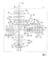
- the illuminating device 2 includes an array light source 21A, a collimator optical system 22, an afocal optical system 23, a first phase difference plate 46, a first motor 47, and a homogenizer optical system. 24, the first prism 25A including the first polarization separation element 50A, the first pickup optical system 26, the first light emitting element 27, the optical element 41, the polarization conversion element 32, and the superposition optical system. 33.
- the 1st light emitting element 27 comprises the wavelength converter in this invention.
- the system 29 and the diffuse reflection element 30 are sequentially arranged on the optical axis ax1 with their optical centers aligned with the optical axis ax1 shown in FIG.
- the first light emitting element 27, the first pickup optical system 26, the first prism 25A, the integrator optical system 31, the polarization conversion element 32, and the superimposing lens 33a illustrate the optical centers thereof. 2 are arranged side by side on the optical axis ax2 in a state of being aligned with the optical axis ax2 shown in FIG.
- the optical axis ax1 and the optical axis ax2 are in the same plane and are in a positional relationship orthogonal to each other.
- the array light source 21A includes a plurality of semiconductor lasers 211.
- the plurality of semiconductor lasers 211 are arranged in an array in a plane 21c orthogonal to the optical axis ax1.
- the number of semiconductor lasers 211 is not particularly limited.
- the semiconductor laser 211 in this embodiment corresponds to the light emitting element in the claims.
- the semiconductor laser 211 emits S-polarized blue light having a peak wavelength of 446 nm, for example.
- the S-polarized blue light BL is emitted from the array light source 21 ⁇ / b> A toward the collimator optical system 22.
- the blue light BL having a peak wavelength of 446 nm in the present embodiment corresponds to the light in the first wavelength band in the claims.
- the blue light BL emitted from the array light source 21A enters the collimator optical system 22.
- the collimator optical system 22 converts the blue light BL emitted from the array light source 21A into a parallel light beam.
- the collimator optical system 22 is composed of, for example, a plurality of collimator lenses 22a arranged in an array.
- the plurality of collimator lenses 22a are arranged corresponding to the plurality of semiconductor lasers 211, respectively.
- Blue light BL converted into a parallel light beam by passing through the collimator optical system 22 is incident on the afocal optical system 23.
- the afocal optical system 23 adjusts the light beam diameter of the blue light BL.
- the afocal optical system 23 includes, for example, an afocal lens 23a and an afocal lens 23b.
- the blue light BL whose beam diameter is adjusted by passing through the afocal optical system 23 is incident on the homogenizer optical system 24.
- the homogenizer optical system 24 converts the light intensity distribution of the blue light BL into, for example, a uniform light intensity distribution called a top hat type distribution.
- the homogenizer optical system 24 includes, for example, a multi-lens array 24a and a multi-lens array 24b.
- a first retardation plate 46 is provided between the afocal optical system 23 and the homogenizer optical system 24, more specifically, on the optical path between the afocal lens 23b and the multi-lens array 24a.
- the first retardation plate 46 is provided so as to be rotatable within a plane on which the blue light BL is incident.
- the first retardation plate 46 is a half-wave plate for the wavelength 446 nm of the blue light BL.
- the optical axis of the first retardation plate 46 intersects with the polarization axis of the blue light BL incident on the first retardation plate 46.
- the optical axis of the first retardation plate 46 may be either the fast axis or the slow axis of the first retardation plate 46.
- Blue light BL is coherent S-polarized light.
- the blue light BL is originally S-polarized light, but the blue light BL passes through the first retardation plate 46 because the polarization axis of the blue light BL intersects the optical axis of the first retardation plate 46.
- part of the S-polarized light is converted to P-polarized light.
- the blue light BL transmitted through the first retardation plate 46 becomes light in which the S-polarized component BLs and the P-polarized component BLp are mixed at a predetermined ratio.
- the S-polarized component BLs in the present embodiment corresponds to the first light flux in the first polarization state in the claims.
- the P-polarized light BLp in the present embodiment corresponds to the second light flux in the second polarization state in the claims.
- a first motor 47 for rotating the first phase difference plate 46 is connected to the first phase difference plate 46.
- the rotation mechanism of the first retardation plate 46 will be described later.
- the blue light BL emitted from the homogenizer optical system 24 is incident on the first prism 25A.
- the first prism 25A is composed of, for example, a dichroic prism having wavelength selectivity.
- the dichroic prism has an inclined surface K that forms an angle of 45 ° with the optical axis ax1.
- the inclined surface K forms an angle of 45 ° with respect to the optical axis ax2.
- the first prism 25A is arranged so that the intersection of the optical axes ax1 and ax2 orthogonal to each other coincides with the optical center of the inclined surface K.
- a parallel plate dichroic mirror may be used.
- the inclined plane K is provided with a first polarization separation element 50A having wavelength selectivity.
- the first polarization separation element 50A has a polarization separation function of separating the blue light BL into an S polarization component BLs and a P polarization component BLp for the first polarization separation element 50A.
- the first polarization separation element 50A reflects the S-polarized component BLs of the blue light BL and transmits the P-polarized component BLp of the blue light BL.
- excitation light BLs since the S-polarized component BLs reflected by the first polarization separation element 50A is used for excitation of the phosphor layer, it is referred to as excitation light BLs.
- the P-polarized component BLp that has passed through the first polarization separation element 50A is used as illumination light, and therefore is referred to as blue light BLp.
- the first polarization separation element 50A has a color separation function of transmitting yellow fluorescent light YL having a wavelength band different from that of the blue light BL emitted from the semiconductor laser 211, regardless of the polarization state of the fluorescent light YL. Have.
- the first pickup optical system 26 condenses the excitation light BLs toward the first phosphor layer 34 of the first light emitting element 27.
- the first pickup optical system 26 includes, for example, a pickup lens 26a and a pickup lens 26b.
- Excitation light BLs emitted from the first pickup optical system 26 enters the first light emitting element 27.
- the first light emitting element 27 includes a first phosphor layer 34 and a substrate 35 that supports the first phosphor layer 34.
- the excitation light BLs enters the first phosphor layer 34, the phosphor contained in the first phosphor layer 34 is excited, and yellow fluorescent light YL having a wavelength different from that of the excitation light BLs is generated.
- the fluorescent light YL in the present embodiment corresponds to the third light flux in the second wavelength band in the claims.
- the first phosphor layer 34 has a side surface opposite to the side on which the excitation light BLs is incident, in contact with the substrate 35, and the side surface of the first phosphor layer 34. It is fixed to the substrate 35 by an adhesive 36 provided between the substrate 35 and the substrate 35.
- a heat sink 38 for dissipating heat from the first phosphor layer 34 is provided on the surface of the substrate 35 opposite to the side on which the first phosphor layer 34 is provided.
- the first fluorescent light YL emitted from the first phosphor layer 34 is non-polarized light whose polarization direction is not uniform, after passing through the first pickup optical system 26, the first fluorescent light YL remains in a non-polarized state.
- the light enters the polarization separation element 50A.
- the fluorescent light YL passes through the first polarization separation element 50A and proceeds toward the integrator optical system 31.
- the P-polarized blue light BLp emitted from the first polarization separation element 50A enters the optical element 41.
- the optical element 41 includes a phase difference plate 28, a second pickup optical system 29, and a diffuse reflection element 30.
- the blue light BLp ′ is incident on the phase difference plate 28.
- the phase difference plate 28 is composed of a quarter-wave plate disposed in the optical path between the polarization separation element 50 ⁇ / b> A and the diffuse reflection element 30. Therefore, the P-polarized blue light BLp emitted from the polarization separation element 50A is converted into circularly-polarized blue light BLc by the phase difference plate 28, and then enters the second pickup optical system 29.
- the second pickup optical system 29 condenses the blue light BLc toward the diffuse reflection element 30.
- the second pickup optical system 29 includes, for example, a pickup lens 29a and a pickup lens 29b.
- the diffuse reflection element 30 diffusely reflects the blue light BLc emitted from the second pickup optical system 29 toward the polarization separation element 50A.
- the diffuse reflection element 30 that causes Lambertian reflection of the blue light BLc incident on the diffuse reflection element 30.
- the blue light BLc ′ diffusely reflected by the diffuse reflection element 30 is incident on the phase difference plate 28 again, thereby converting the circularly polarized blue light BLc ′ to the S-polarized blue light BLs ′. Is done. Therefore, S-polarized blue light BLs ′ is emitted from the optical element 41.
- the S-polarized blue light BLs ′ in the present embodiment corresponds to the fourth light beam in the claims.
- the S-polarized blue light BLs' is incident on the polarization separation element 50A.
- the S-polarized blue light BLs ′ is reflected by the polarization separation element 50 ⁇ / b> A and travels toward the integrator optical system 31.
- the blue light BLs ′ is used as the illumination light WL together with the fluorescent light YL transmitted through the polarization separation element 50A. That is, the blue light BLs' and the fluorescent light YL are emitted from the polarization separation element 50A in the same direction. In this way, white illumination light WL obtained by combining the blue light BLs ′ and the yellow fluorescent light YL is obtained. That is, the polarization separation element 50A also functions as a color synthesis element that synthesizes the blue light BLs' and the fluorescent light YL.
- the polarization separation element 50A in the present embodiment corresponds to the first color composition element in the claims.
- the illumination light WL emitted from the polarization separation element 50A enters the integrator optical system 31.
- the integrator optical system 31 divides the illumination light WL into a plurality of small light beams.
- the integrator optical system 31 includes, for example, a first lens array 31a and a second lens array 31b.
- the first lens array 31a and the second lens array 31b are composed of a plurality of microlenses arranged in an array.
- the illumination light WL (a plurality of small light beams) emitted from the integrator optical system 31 enters the polarization conversion element 32.
- the polarization conversion element 32 aligns the polarization direction of the illumination light WL.
- the polarization conversion element 32 includes, for example, a polarization separation film, a phase difference plate, and a mirror.
- the polarization conversion element 32 aligns the polarization direction of the non-polarized fluorescent light YL and the polarization direction of the S-polarized blue light BLs ′, so that the other polarization component is set to one polarization component, for example, the P-polarization component is converted to S-polarization. Convert to component.
- the illumination light WL whose polarization direction is aligned by passing through the polarization conversion element 32 enters the superimposing lens 33.
- the superimposing lens 33 superimposes a plurality of small light beams emitted from the polarization conversion element 32 on the illumination object. Thereby, an illumination target object can be illuminated uniformly.
- the superimposing optical system 33 includes an integrator optical system 31 including a first lens array 31a and a second lens array 31b, and a superimposing lens 33a.
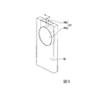
- the first retardation plate 46 is formed of a circular plate 46a, and is provided with a rod-like portion 46b that protrudes outward from the plate 46a.
- the first retardation plate 46 is rotatably held by a holding member 49.
- the rod-like portion 46 b of the first retardation plate 46 protrudes outside the holding member 49.
- the first retardation plate 46 rotates when the rod-like portion 46 b moves in a direction along the main surface of the holding member 49.
- a spring 55 is inserted in a space between the rod-like portion 46 b of the first retardation plate 46 and the wall portion 49 a of the holding member 49.
- a screw member 51 is fixed to the tip of the rotation shaft 47 a of the first motor 47.
- the screw member 51 pushes the rod-like portion 46b in the direction of arrow A in FIG. 4, and the first retardation plate 46 rotates counterclockwise.
- the first retardation plate 46 rotates clockwise by the action of the spring 55 and returns to the neutral position.
- the optical axis 46c of the first retardation plate 46 rotates.
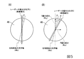
- FIG. 5A is a diagram illustrating a polarization state of light before passing through the first retardation plate 46.
- FIG. 5B is a diagram illustrating a polarization state of light after passing through the first retardation plate 46.
- the blue light BL before passing through the first retardation plate 46 is S-polarized light (linearly polarized light).
- S-polarized light linearly polarized light
- the polarization direction P1 of S-polarized light and the optical axis 46c of the first phase difference plate 46 intersect to form an angle ⁇ .
- the polarization direction P1 rotates clockwise by an angle 2 ⁇ to become the polarization direction P2.
- the S-polarized component BLs and the P-polarized component BLp are generated, and the ratio of the light amount of the S-polarized component BLs and the light amount of the P-polarized component BLp is cos (2 ⁇ ): sin (2 ⁇ ).
- ⁇ 2 °
- the ratio of the light amount of the S-polarized component BLs to the light amount of the P-polarized component BLp is 14.3: 1.
- the amount of the P-polarized component BLp relative to the S-polarized component BLs can be relatively increased by increasing the rotation angle ⁇ of the first retardation plate 46. it can.
- the amount of the yellow fluorescent light YL is relatively increased with respect to the light amount of the blue light BLs ′, so that the combined light is changed to yellowish white light.
- the amount of the P-polarized component BLp relative to the S-polarized component BLs can be relatively reduced.
- the amount of the yellow fluorescent light YL is relatively decreased with respect to the amount of the blue light BLs ′, so that the combined light changes to white light with a blue tinge.
- the control device 44 changes the direction of the optical axis of the first retardation plate 46 according to the color mode selection result in the color mode selection switch 43. Specifically, the control device 44 outputs a drive signal to the first motor 47 and rotates the first phase difference plate 46 in a direction in which the rotation angle ⁇ of the first phase difference plate 46 is increased.
- the light quantity of yellow fluorescent light with respect to the light quantity of blue light increases relatively, and the brightness
- FIG. 6 is a graph showing the spectrum of illumination light when the rotation angle of the first retardation plate 46 is changed.
- the horizontal axis of the graph is the wavelength [nm]
- the vertical axis of the graph is the intensity of illumination light [au (arbitrary unit)].
- the color of the illumination light can be represented by color temperature or color deviation.
- FIG. 7 is a graph showing the relationship between the rotation angle of the first retardation plate 46 and the color temperature of the emitted light.
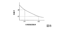
- FIG. 8 is a graph showing the relationship between the rotation angle of the first retardation plate 46 and the color deviation of the emitted light.
- the luminance and color balance of the illumination light can be controlled by changing the rotation angle of the first retardation plate 46.
- emitted from the illuminating device 2 can be adjusted according to the selected color mode. Therefore, it is possible to adjust the brightness, color tone, and the like of the image while suppressing the loss of brightness of the image as compared with the conventional projector that relies only on the adjustment of the gamma characteristic of the light modulation element.
- FIG. 9 is a schematic configuration diagram of the illumination device in the projector according to the second embodiment. 9, the same code
- the wavelength conversion device is configured by the light emitting element 27.
- the wavelength converter includes a second retardation plate 62, a second prism 64 including a second polarization separation element 63, and a second light emission.
- An element 65, a third light emitting element 66, a third pickup optical system 67, and a fourth pickup optical system 68 are included.
- a second phase difference plate 62 is provided on the optical path between the first prism 25A and the second prism 64.
- the second retardation plate 62 is provided so as to be rotatable in the plane of the main surface on which light is incident.
- the second retardation plate 62 is a half-wave plate for blue light having a wavelength of 446 nm.
- the optical axis of the second retardation plate 62 intersects with the polarization axis of the blue light BLs emitted from the first prism 25A.
- the optical axis of the second retardation plate 62 may be either the fast axis or the slow axis of the second retardation plate 62.
- the blue light BLs transmitted through the second retardation plate 62 becomes light in which the S-polarized component BLs2 and the P-polarized component BLp2 are mixed at a predetermined ratio.
- a second motor 69 for rotating the second phase difference plate 62 is connected to the second phase difference plate 62.
- the support structure and rotation mechanism of the second retardation plate 62 are the same as the support structure and rotation mechanism of the first retardation plate, and the description thereof is omitted.
- the S-polarized component BLs2 and the P-polarized component BLp2 are incident on the second prism 64.
- the second prism 64 is constituted by a dichroic prism having wavelength selectivity, for example.
- a parallel plate dichroic mirror may be used instead of the second prism 64 formed of a dichroic prism.
- a second polarization separation element 63 having wavelength selectivity is provided on the inclined surface K of the dichroic prism.
- the second polarization separation element 63 transmits the P-polarized component BLp2 and reflects the S-polarized component BLs2.
- red excitation light BLs2 since the S-polarized light component reflected by the second polarization separation element 63 is used for excitation of a red phosphor layer described later, it is referred to as red excitation light BLs2.
- the P-polarized light component transmitted through the second polarization separation element 63 is used for excitation of a green phosphor layer, which will be described later, and hence is referred to as green excitation light BLp2.
- the green phosphor layer and the red phosphor layer respectively correspond to the first phosphor layer and the second phosphor layer in the claims.
- the second polarization separation element 63 reflects the red fluorescent light RL having a wavelength band different from that of the blue light BL, regardless of the polarization state of the red fluorescent light RL, and has a wavelength band different from that of the blue light BL. It has a color separation function that transmits green fluorescent light GL regardless of the polarization state of green fluorescent light GL.
- the green excitation light BLp 2 emitted from the second polarization separation element 63 is incident on the third pickup optical system 67.
- the third pickup optical system 67 condenses the green excitation light BLp2 toward the green phosphor layer 74 of the second light emitting element 65.
- the third pickup optical system 67 includes, for example, a pickup lens 67a and a pickup lens 67b.
- the green excitation light BLp 2 emitted from the third pickup optical system 67 is incident on the second light emitting element 65.
- the second light emitting element 65 includes a green phosphor layer 74, a substrate 35 that supports the green phosphor layer 74, and a heat sink 38.
- the green excitation light BLs enters the green phosphor layer 74, the phosphor included in the green phosphor layer 74 is excited, and green fluorescent light GL having a wavelength different from that of the green excitation light BLp2 is generated.
- the fluorescent light GL in the present embodiment corresponds to the fifth light flux in the third wavelength band in the claims.
- the green fluorescent light GL emitted from the green phosphor layer 74 passes through the third pickup optical system 67 and then passes through the second polarization separation element 63 regardless of the polarization state.
- the red excitation light BLs2 emitted from the second polarization separation element 63 is incident on the fourth pickup optical system 68.
- the fourth pickup optical system 68 condenses the red excitation light BLs 2 toward the red phosphor layer 75 of the third light emitting element 66.
- the fourth pickup optical system 68 includes, for example, a pickup lens 68a and a pickup lens 68b.
- the red excitation light BLs 2 emitted from the fourth pickup optical system 68 is incident on the third light emitting element 66.
- the third light emitting element 66 includes a red phosphor layer 75, a substrate 35 that supports the red phosphor layer 75, and a heat sink 38.
- red excitation light BLs2 enters the red phosphor layer 75
- the phosphor contained in the red phosphor layer 75 is excited, and red fluorescent light RL having a wavelength different from that of the red excitation light BLs2 is generated.
- the red fluorescent light RL in the present embodiment corresponds to the sixth light flux in the fourth wavelength band in the claims.
- the red fluorescent light RL emitted from the red phosphor layer 75 passes through the fourth pickup optical system 68 and is then reflected by the second polarization separation element 63. Therefore, the green fluorescent light GL transmitted through the second polarization separation element 63 and the red fluorescent light RL reflected by the second polarization separation element 63 are combined into yellow fluorescent light YL, and the yellow fluorescent light YL Is emitted from the second polarization separation element 63. That is, the second polarized light separating element 63 functions as a color synthesizing element that synthesizes the green fluorescent light GL and the red fluorescent light RL. The yellow fluorescent light YL synthesized by the second polarization separation element 63 passes through the second retardation plate 62.
- the second polarization separation element 63 in the present embodiment corresponds to the second color composition element in the claims.
- the color mode selection switch 43 is the same as that in the first embodiment.
- the control device 44 determines the direction of the optical axis of the first retardation plate 46 and the optical axis of the second retardation plate 62 according to the color mode selection result in the color mode selection switch 43. Change both directions.
- the second retardation plate 62 is rotated by a predetermined angle, so that the light quantity of the S-polarized component BLs2 and the P-polarized component BLp2 generated by the second retardation plate 62 are changed.
- the ratio with the amount of light can be adjusted. For example, by relatively increasing the light amount of the P-polarized component BLp2 and relatively decreasing the light amount of the S-polarized component BLs2, the light amount of the red fluorescent light RL is relatively decreased and the light amount of the green fluorescent light GL is relatively increased. be able to.
- the light amount of the red fluorescent light RL is relatively increased and the light amount of the green fluorescent light GL is relatively increased. Can be reduced. Thereby, the brightness
- the luminance and color balance of the yellow fluorescent light YL which is the combined light of the red fluorescent light RL and the green fluorescent light GL
- the rotation angle of the second retardation plate 62 After adjustment, the brightness and color balance of white light, which is a combined light of blue light and yellow light, can be adjusted by controlling the rotation angle of the first retardation plate 46.
- the control device 44 changes the direction of the optical axis of the second retardation plate 62 according to the color mode selection result in the color mode selection switch 43. Specifically, the control device 44 outputs a drive signal to the second motor 69 to change the rotation angle ⁇ of the second phase difference plate 62.
- the rate of change in the conversion efficiency of the phosphor with respect to the change in the light density of the excitation light is determined by the green phosphor layer, the red phosphor layer, and the like. Generally, it is different. From this, after adjusting the brightness
- the direction of the optical axis of the first retardation plate 46 and the direction of the optical axis of the second retardation plate 62 are both changed according to the color mode selection result.
- the optical axis direction of the first retardation plate 46 and the optical axis direction of the second retardation plate 62 may be changed.
- FIG. 10 is a schematic configuration diagram of a lighting apparatus according to the third embodiment.
- the same components as those in FIG. 2 used in the first embodiment and FIG. 9 used in the second embodiment are denoted by the same reference numerals, and description thereof is omitted.
- the lower configuration is the same as that of the illumination device 60 of the second embodiment.
- the first retardation plate 46 and the first motor 47 provided in the illumination device 60 of the second embodiment are not provided in the illumination device 80.
- all of the blue light BL emitted from the semiconductor laser 211 is incident on the first polarization separation element 50A as S-polarized light.
- the blue light BL incident on the first polarization separation element 50A is reflected by the first polarization separation element 50A and used as excitation light for exciting the green phosphor layer 74 or the red phosphor layer 75.
- the blue light source device 81 is provided on the side opposite to the side on which the semiconductor laser 211 is provided with the first prism 25A interposed therebetween.
- the blue light source device 81 is for emitting blue light BLh used as illumination light.
- the blue light source device 81 includes an array light source 82, a collimator optical system 83, an afocal optical system 84, a homogenizer optical system 85, a fifth pickup optical system 86, a light diffusing element 87, a sixth And a pickup optical system 88.
- the array light source 82 includes a plurality of semiconductor lasers 212.
- the plurality of semiconductor lasers 212 are arranged side by side in an array within a surface 21d orthogonal to the optical axis ax1.
- the number of semiconductor lasers 212 is not particularly limited.
- the semiconductor laser 212 emits P-polarized blue light having a peak wavelength of 460 nm.
- the P-polarized blue light BLh is emitted from the array light source 82 toward the collimator optical system 83.
- the blue light BLh emitted from the array light source 82 enters the collimator optical system 83.
- the collimator optical system 83 converts the blue light BLh emitted from the array light source 82 into a parallel light beam.
- the collimator optical system 83 is composed of, for example, a plurality of collimator lenses 83a arranged in an array.
- the plurality of collimator lenses 83a are arranged corresponding to the plurality of semiconductor lasers 212, respectively.
- Blue light BLh converted into a parallel light beam by passing through the collimator optical system 83 is incident on the afocal optical system 84.
- the afocal optical system 84 adjusts the beam diameter of the blue light BLh.
- the afocal optical system 84 includes, for example, an afocal lens 84a and an afocal lens 84b.
- the blue light BLh whose beam diameter is adjusted by passing through the afocal optical system 84, enters the homogenizer optical system 85.
- the homogenizer optical system 85 converts the light intensity distribution of the blue light BLh into a uniform light intensity distribution called, for example, a top hat type distribution.
- the homogenizer optical system 85 includes, for example, a multi lens array 85a and a multi lens array 85b.
- the blue light BLh emitted from the homogenizer optical system 85 enters the fifth pickup optical system 86.
- the fifth pickup optical system 86 condenses the blue light BLh toward the light diffusing element 87.
- the fifth pickup optical system 86 includes a pickup lens 86a and a pickup lens 86b.
- the light diffusing element 87 diffuses the blue light BLh emitted from the fifth pickup optical system 86 while transmitting it.
- the blue light BLh having a uniform illuminance distribution is obtained by diffusing the blue light BLh by the light diffusing element 87.
- Blue light BLh emitted from the light diffusing element 87 is incident on the first prism 25A via the sixth pickup optical system 88.
- the sixth pickup optical system 88 includes a pickup lens 88a and a pickup lens 88b. Since the blue light BLh is P-polarized light, it is reflected by the first polarization separation element 50A of the first prism 25A. As a result, the first polarization separation element 50A combines the blue light BLh reflected by the first polarization separation element 50A and the yellow fluorescent light YL transmitted through the first polarization separation element 50A to produce the white light WL. Generate.
- Other configurations are the same as those of the illumination device 60 of the second embodiment.
- the yellow fluorescent light YL that is the combined light of the red fluorescent light RL and the green fluorescent light GL is controlled by controlling the rotation angle of the second retardation plate 62 according to the color mode.
- the brightness and color balance can be adjusted.
- the white light WLh is controlled by controlling the output of the blue light BLh emitted from the semiconductor laser 212 of the blue light source device 81 according to the amount of the yellow fluorescent light YL transmitted through the first polarization separation element 50A. Adjust the brightness and color balance.
- the illumination device 80 by using the illumination device 80, it is possible to realize a projector capable of adjusting the brightness, color tone, and the like of the image according to the color mode while suppressing the loss of brightness of the image.
- the description was made without changing the names of the optical components common to the second embodiment.
- the correspondence relationship with the constituent elements in the claims is different from that of the second embodiment.
- the P-polarized component BLp2 and the S-polarized component BLs2 emitted from the second prism 64 correspond to the first light beam and the second light beam, respectively.
- the second retardation plate 62 in the present embodiment corresponds to the first retardation plate in the claims.
- the second polarization separation element 63 in the present embodiment corresponds to the first polarization separation element in the claims.
- the second light emitting element 65 corresponds to the wavelength conversion device in the claims.
- the green phosphor layer 74 in the present embodiment corresponds to the first phosphor layer in the claims.
- the third light emitting element 66 in the present embodiment corresponds to the optical element in the claims.
- the second polarization separation element 63 in the present embodiment corresponds to the first color composition element in the claims.
- the first retardation plate is a half-wave plate with respect to the wavelength 446 nm of blue light, but is not limited thereto. Any transparent optical element that can change the polarization state by rotation may be used. For example, a quarter wavelength plate may be used.
- a projector including three light modulation devices has been exemplified.
- the present invention can also be applied to a projector that displays a color image (image) with a single light modulation device.
- the number, size, arrangement, and the like of various constituent elements of the light emitting element, the lighting device, and the projector disclosed in the above embodiment can be appropriately changed.
- an example of a projector using a liquid crystal light modulation device has been described, but the present invention is not limited to this. You may mount in the projector using a digital micromirror device as a light modulation apparatus.
- the phosphor layer is used as the wavelength conversion device, but the present invention is not limited to this.
- a quantum rod or the like may be used as the wavelength conversion element.
Landscapes
- Physics & Mathematics (AREA)
- General Physics & Mathematics (AREA)
- Optics & Photonics (AREA)
- Engineering & Computer Science (AREA)
- Multimedia (AREA)
- Signal Processing (AREA)
- Projection Apparatus (AREA)
- Transforming Electric Information Into Light Information (AREA)
- Optical Filters (AREA)
- Polarising Elements (AREA)
Abstract
カラーモードに伴い色バランスを調整できるプロジェクターを提供する。 本発明のプロジェクターは、照明装置と、光変調装置と、投射光学系と、カラーモード選択部と、を備える。照明装置は、第1の波長帯の光を射出する発光素子と、発光素子からの光が入射する第1の位相差板と、第1の位相差板からの光を、第1の偏光状態の第1の光束と第2の偏光状態の第2の光束とに分離する第1の偏光分離素子と、第1の波長帯の光によって励起される第1の蛍光体層を備え、第1の光束を、第1の波長帯とは異なる第2の波長帯の第3の光束に変換する波長変換装置と、第2の光束を第4の光束に変換する光学素子と、第3の光束と第4の光束とを合成する第1の色合成素子と、カラーモード選択部での選択結果に応じて第1の位相差板の光学軸の方向を変化させる制御装置と、を備える。
Description
本発明は、プロジェクターに関する。
使用者が画像の明るさ、コントラスト、色合い等を表すパラメーターを選択することにより画質調整を行うことが可能なプロジェクターが提供されている。使用者は、上記のパラメーターを、例えば画像の種別(静止画、動画)、画像のコンテンツ(映画、スポーツ、ニュース等)、あるいは部屋の明るさ等の視聴環境に応じて適宜選択することができる。
下記の特許文献1および2には、使用者がカラーモードを任意に選択することができるプロジェクターが開示されている。「カラーモード」とは、画像の種別、画像のコンテンツ、あるいは視聴環境に応じた明るさまたは色調等を設定するための項目である。
特許文献1および2に示したカラーモードを備えた従来のプロジェクターでは、カラーモードに応じて液晶パネル等の光変調素子のガンマ特性を切り換える方法により画像の色調、明るさ等を調整していた。そのため、選択されたモードによっては、光源からの射出光の光量を光変調素子で大きく低下させる必要があるため、画像の明るさロスが大きい、という問題があった。逆に、画像の明るさロスを最小限に抑えようとすると、画像の色調、明るさ等が十分に調整できないという問題があった。
本発明の一つの態様は、画像の明るさロスを抑えつつ、カラーモードに応じて画像の明るさ、色調等を調整することができるプロジェクターを提供することを目的の一つとする。
上記の目的を達成するために、本発明の一つの態様のプロジェクターは、照明装置と、前記照明装置から射出された光を画像情報に応じて変調する光変調装置と、前記光変調装置により変調された光を投射する投射光学系と、複数のカラーモードのうちのいずれかを選択するためのカラーモード選択部と、を備え、前記照明装置は、第1の波長帯の光を射出する発光素子と、前記発光素子から射出された光が入射する第1の位相差板と、前記第1の位相差板からの光を、第1の偏光状態の第1の光束と第2の偏光状態の第2の光束とに分離する第1の偏光分離素子と、前記第1の波長帯の光によって励起される第1の蛍光体層を備え、前記第1の光束を、前記第1の波長帯とは異なる第2の波長帯の第3の光束に変換する波長変換装置と、前記第2の光束を第4の光束に変換する光学素子と、前記第3の光束と前記第4の光束とを合成する第1の色合成素子と、前記カラーモード選択部での選択結果に応じて前記第1の位相差板の光学軸の方向を変化させる制御装置と、を備える。
本発明の一つの態様のプロジェクターにおいては、制御装置が、カラーモード選択部での選択結果に応じて第1の位相差板の光学軸の方向を変化させることにより第1の偏光状態の第1の光束と第2の偏光状態の第2の光束との割合を調整する。このようにして、第1の光束から得られる第3の光束の量と第2の光束から得られる第4の光束の量とを調整できるため、選択されたカラーモードに応じて照明装置から射出される光の輝度や色バランスを調整できる。これにより、光変調素子のガンマ特性の調整のみに依っていた従来のプロジェクターに比べて画像の明るさロスを抑えつつ、画像の明るさ、色調等を調整することができる。
本発明の一つの態様のプロジェクターにおいて、前記制御装置は、前記複数のカラーモードのうち明るさ重視モードが選択された場合に、他のカラーモードが選択された場合に比べて前記第3の光束の光量を増加させるように、前記第1の位相差板の光学軸の方向を変化させてもよい。
この構成によれば、波長変換装置により波長変換された第3の光束の光量を増加させることにより、照明装置から射出される光の光量を効果的に増加させ、明るい画像を得ることができる。
本発明の一つの態様のプロジェクターにおいて、前記第1の蛍光体層は、前記第1の波長帯および前記第2の波長帯のいずれとも異なる第3の波長帯の第5の光束を射出し、前記波長変換装置は、前記第1の波長帯の光によって励起され、前記第1ないし第3の波長帯のいずれとも異なる第4の波長帯の第6の光束を射出する第2の蛍光体層と、前記第1の光束が入射する第2の位相差板と、前記第2の位相差板から射出された光を、前記第1の蛍光体層に入射する偏光成分と、前記第2の蛍光体層に入射する偏光成分と、に分離する第2の偏光分離素子と、前記第5の光束と前記第6の光束とを合成して前記第3の光束を生成する第2の色合成素子と、を備え、前記制御装置は、前記カラーモード選択部での選択結果に応じて前記第2の位相差板の光学軸の方向を変化させてもよい。
この態様のプロジェクターは、カラーモード選択部での選択結果に応じて第2の位相差板の光学軸の方向を変化させる制御装置を備えている。そのため、第2の位相差板の光学軸の方向を変化させることにより、第1の蛍光体層に入射する偏光成分と第2の蛍光体層に入射する偏光成分との割合が調整される。このようにして、第1の蛍光体層によって生成される第5の光束の量と第2の蛍光体層によって生成される第6の光束の量を調整し、第6の光束の色バランスを調整できる。さらに、第5の光束と第6の光束との合成光である第3の光束の量と第2の光束から得られる第4の光束の量とを調整することにより、照明装置からの射出光の色バランスを調整できる。
本発明の一つの態様のプロジェクターにおいて、前記制御装置は、前記複数のカラーモードのうち明るさ重視モードが選択された場合に、他のカラーモードが選択された場合に比べて前記第6の光束の光量を増加させるように、前記第2の位相差板の光学軸の方向を変化させてもよい。
この構成によれば、波長変換装置により波長変換された第6の光束の光量を増加させることにより、照明装置から射出される光の光量を効果的に増加させ、明るい画像を得ることができる。
[第1実施形態]
以下、本発明の第1実施形態について、図1~図8を用いて説明する。
第1実施形態のプロジェクターは、照明装置と、3つの光変調装置と、を備えた液晶プロジェクターの例である。
以下、図面を用いて具体的に説明するが、以下の各図面においては各構成要素を見やすくするため、構成要素によって寸法の縮尺を異ならせて示すことがある。
以下、本発明の第1実施形態について、図1~図8を用いて説明する。
第1実施形態のプロジェクターは、照明装置と、3つの光変調装置と、を備えた液晶プロジェクターの例である。
以下、図面を用いて具体的に説明するが、以下の各図面においては各構成要素を見やすくするため、構成要素によって寸法の縮尺を異ならせて示すことがある。
図1に示すように、本実施形態のプロジェクター1は、スクリーンSCR上にカラー画像を表示する投射型画像表示装置である。プロジェクター1には、赤色光LR、緑色光LG、および青色光LBの各色光に対応した3つの光変調装置が用いられる。プロジェクター1には、照明装置2の光源として、高輝度・高出力の光が得られる半導体レーザーが用いられる。プロジェクター1は、照明装置2と、色分離光学系3と、赤色光用光変調装置4Rと、緑色光用光変調装置4Gと、青色光用光変調装置4Bと、合成光学系5と、投射光学系6と、カラーモード選択スイッチ43と、制御装置44と、を概略備えている。
照明装置2は、均一な照度分布を有する照明光WLを色分離光学系3に向けて射出する。照明装置2には、後述する本発明の一つの実施形態である照明装置が用いられる。
色分離光学系3は、照明装置から射出された照明光WLを赤色光LRと緑色光LGと青色光LBとに分離する。色分離光学系3は、第1のダイクロイックミラー7aと、第2のダイクロイックミラー7bと、第1の反射ミラー8aと、第2の反射ミラー8bと、第3の反射ミラー8cと、第1のリレーレンズ9aと、第2のリレーレンズ9bと、を備えている。
第1のダイクロイックミラー7aは、照明装置2から射出された照明光WLを赤色光LRと、緑色光LGおよび青色光LBと、に分離する機能を有する。第1のダイクロイックミラー7aは、赤色光LRを透過し、緑色光LGおよび青色光LBを反射する。第2のダイクロイックミラー7bは、第1のダイクロイックミラー7aで反射した光を緑色光LGと青色光LBとに分離する機能を有する。第2のダイクロイックミラー7bは、緑色光LGを反射し、青色光LBを透過する。
第1の反射ミラー8aは、赤色光LRの光路中に配置されている。第1の反射ミラー8aは、第1のダイクロイックミラー7aを透過した赤色光LRを赤色光用光変調装置4Rに向けて反射する。第2の反射ミラー8bと第3の反射ミラー8cとは、青色光LBの光路中に配置されている。第2の反射ミラー8bと第3の反射ミラー8cとは、第2のダイクロイックミラー7bを透過した青色光LBを青色光用光変調装置4Bに向けて反射させる。緑色光LGは、第2のダイクロイックミラー7bで反射し、緑色光用光変調装置4Gに向けて進む。
第1のリレーレンズ9aと第2のリレーレンズ9bとは、青色光LBの光路中における第2のダイクロイックミラー7bの光射出側に配置されている。第1のリレーレンズ9aと第2のリレーレンズ9bとは、青色光LBの光路長が赤色光LRや緑色光LGの光路長よりも長くなることに起因した青色光LBの光損失を補償する機能を有している。
赤色光用光変調装置4Rは、赤色光LRを画像情報に応じて変調し、赤色光LRに対応した画像光を形成する。緑色光用光変調装置4Gは、緑色光LGを画像情報に応じて変調し、緑色光LGに対応した画像光を形成する。青色光用光変調装置4Bは、青色光LBを画像情報に応じて変調し、青色光LRに対応した画像光を形成する。
赤色光用光変調装置4R、緑色光用光変調装置4G、および青色光用光変調装置4Bには、例えば透過型の液晶パネルが用いられる。また、液晶パネルの入射側および射出側には、図示しない一対の偏光板が配置されている。一対の偏光板は、特定の方向の直線偏光光を透過させる。
赤色光用光変調装置4Rの入射側には、フィールドレンズ10Rが配置されている。緑色光用光変調装置4Gの入射側には、フィールドレンズ10Gが配置されている。青色光用光変調装置4Bの入射側には、フィールドレンズ10Bが配置されている。フィールドレンズ10Rは、赤色光用光変調装置4Rに入射する赤色光LRを平行化する。フィールドレンズ10Gは、緑色光用光変調装置4Gに入射する緑色光LGを平行化する。フィールドレンズ10Bは、青色光用光変調装置4Bに入射する赤色光LBを平行化する。
合成光学系5は、赤色光LR、緑色光LG、および青色光LBのそれぞれに対応した画像光を合成し、合成された画像光を投射光学系6に向けて射出する。合成光学系5には、例えばクロスダイクロイックプリズムが用いられる。
投射光学系6は、複数の投射レンズを含む投射レンズ群から構成されている。投射光学系6は、合成光学系5により合成された画像光をスクリーンSCRに向けて拡大投射する。これにより、スクリーンSCR上には、拡大されたカラー画像が表示される。
カラーモード選択スイッチ43(図2参照)は、画像の種別(静止画、動画)、画像のコンテンツ(映画、スポーツ、ニュース等)、あるいは部屋の明るさ等の視聴環境に応じて、使用者が下記の複数のカラーモードのうちのいずれかを選択するためのスイッチである。本実施形態のカラーモード選択スイッチ43は、特許請求の範囲のカラーモード選択部に対応する。
複数のカラーモードとしては、例えば、明るい環境での視聴に適した「ダイナミックモード」、薄明かりの中での視聴に適した「リビングモード」、暗い環境下で入力信号に忠実な画像を再現可能な「ナチュラルモード」、暗い環境下での映画鑑賞に適した「シアターモード」等が挙げられる。例えば、「ダイナミックモード」は、画像の色調よりも画像の明るさを重視した明るさ重視モードである。
制御装置44(図2参照)は、カラーモード選択スイッチ43におけるカラーモードの選択結果に応じて、後述する第1の位相差板46の光学軸の方向を変化させる。その他、制御装置44は、従来の制御装置と同様、赤色光用光変調装置4R、緑色光用光変調装置4G、および青色光用光変調装置4Bに入力する画像情報を制御する。
以下、照明装置2について説明する。
図2に示すように、照明装置2は、アレイ光源21Aと、コリメーター光学系22と、アフォーカル光学系23と、第1の位相差板46と、第1のモーター47と、ホモジナイザー光学系24と、第1の偏光分離素子50Aを含む第1のプリズム25Aと、第1のピックアップ光学系26と、第1の発光素子27と、光学素子41と、偏光変換素子32と、重畳光学系33と、を備えている。第1の発光素子27は、本発明における波長変換装置を構成する。
図2に示すように、照明装置2は、アレイ光源21Aと、コリメーター光学系22と、アフォーカル光学系23と、第1の位相差板46と、第1のモーター47と、ホモジナイザー光学系24と、第1の偏光分離素子50Aを含む第1のプリズム25Aと、第1のピックアップ光学系26と、第1の発光素子27と、光学素子41と、偏光変換素子32と、重畳光学系33と、を備えている。第1の発光素子27は、本発明における波長変換装置を構成する。
上記の構成要件のうち、アレイ光源21Aと、コリメーター光学系22と、アフォーカル光学系23と、ホモジナイザー光学系24と、第1のプリズム25Aと、位相差板28と、第2のピックアップ光学系29と、拡散反射素子30とは、それぞれの光学中心を図2中に示す光軸ax1に一致させた状態で、光軸ax1上に順次並んで配置されている。一方、第1の発光素子27と、第1のピックアップ光学系26と、第1のプリズム25Aと、インテグレータ光学系31と、偏光変換素子32と、重畳レンズ33aとは、それぞれの光学中心を図2中に示す光軸ax2に一致させた状態で、光軸ax2上に順次並んで配置されている。光軸ax1と光軸ax2とは、同一面内にあり、互いに直交する位置関係にある。
アレイ光源21Aは、複数の半導体レーザー211を備える。複数の半導体レーザー211は、光軸ax1と直交する面21c内において、アレイ状に並んで配置されている。半導体レーザー211の個数は特に限定されない。本実施形態における半導体レーザー211は、特許請求の範囲における発光素子に対応する。
半導体レーザー211は、例えばピーク波長が446nmのS偏光の青色光を射出する。S偏光の青色光BLは、アレイ光源21Aからコリメーター光学系22に向けて射出される。本実施形態におけるピーク波長が446nmの青色光BLは、特許請求の範囲における第1の波長帯の光に対応する。
アレイ光源21Aから射出された青色光BLは、コリメーター光学系22に入射する。コリメーター光学系22は、アレイ光源21Aから射出された青色光BLを平行光束に変換する。コリメーター光学系22は、例えばアレイ状に並んで配置された複数のコリメーターレンズ22aで構成されている。複数のコリメーターレンズ22aは、複数の半導体レーザー211にそれぞれ対応して配置されている。
コリメーター光学系22を透過することにより平行光束に変換された青色光BLは、アフォーカル光学系23に入射する。アフォーカル光学系23は、青色光BLの光束径を調整する。アフォーカル光学系23は、例えばアフォーカルレンズ23a,アフォーカルレンズ23bから構成されている。
アフォーカル光学系23を透過することにより光束径が調整された青色光BLは、ホモジナイザー光学系24に入射する。ホモジナイザー光学系24は、青色光BLの光強度分布を、例えばトップハット型分布と呼ばれる均一な光強度分布に変換する。ホモジナイザー光学系24は、例えばマルチレンズアレイ24a,マルチレンズアレイ24bから構成されている。
アフォーカル光学系23とホモジナイザー光学系24との間、より具体的には、アフォーカルレンズ23bとマルチレンズアレイ24aとの間の光路上に、第1の位相差板46が設けられている。第1の位相差板46は、青色光BLが入射する面内で回転可能に設けられている。第1の位相差板46は、青色光BLの波長446nmに対する1/2波長板で構成されている。第1の位相差板46の光学軸は、第1の位相差板46に入射する青色光BLの偏光軸と交差する。なお、第1の位相差板46の光学軸は、第1の位相差板46の進相軸もしくは遅相軸のいずれであってもよい。
青色光BLは、コヒーレントなS偏光である。青色光BLはもともとS偏光であるが、青色光BLの偏光軸が第1の位相差板46の光学軸と交差しているため、青色光BLが第1の位相差板46を透過することによりS偏光の一部がP偏光に変換される。その結果、第1の位相差板46を透過した青色光BLは、S偏光成分BLsとP偏光成分BLpとが所定の割合で混在した光となる。例えば、本実施形態におけるS偏光成分BLsは、特許請求の範囲における第1の偏光状態の第1の光束に対応する。本実施形態におけるP偏光BLpは、特許請求の範囲における第2の偏光状態の第2の光束に対応する。
第1の位相差板46に、第1の位相差板46を回転させるための第1のモーター47が接続されている。第1の位相差板46の回転機構については後述する。
ホモジナイザー光学系24から射出された青色光BLは、第1のプリズム25Aに入射する。第1のプリズム25Aは、例えば波長選択性を有するダイクロイックプリズムで構成されている。ダイクロイックプリズムは、光軸ax1に対して45°の角度をなす傾斜面Kを有している。傾斜面Kは、光軸ax2に対しても45°の角度をなしている。第1のプリズム25Aは、互いに直交する光軸ax1,ax2の交点と傾斜面Kの光学中心とが一致するように配置されている。ダイクロイックプリズムからなる第1のプリズム25Aに代えて、平行平板状のダイクロイックミラーを用いてもよい。
傾斜面Kには、波長選択性を有する第1の偏光分離素子50Aが設けられている。第1の偏光分離素子50Aは、青色光BLを、第1の偏光分離素子50Aに対するS偏光成分BLsとP偏光成分BLpとに分離する偏光分離機能を有している。具体的に、第1の偏光分離素子50Aは、青色光BLのS偏光成分BLsを反射させ、青色光BLのP偏光成分BLpを透過させる。以下の説明では、第1の偏光分離素子50Aで反射したS偏光成分BLsは蛍光体層の励起に利用されるため、励起光BLsと称する。第1の偏光分離素子50Aを透過したP偏光成分BLpは照明光として利用されるため、青色光BLpと称する。
また、第1の偏光分離素子50Aは、半導体レーザー211から射出された青色光BLとは波長帯が異なる黄色の蛍光光YLを、蛍光光YLの偏光状態に依らずに透過させる色分離機能を有している。
第1の偏光分離素子50Aから射出されたS偏光の励起光BLsは、第1のピックアップ光学系26に入射する。第1のピックアップ光学系26は、励起光BLsを第1の発光素子27の第1の蛍光体層34に向けて集光させる。第1のピックアップ光学系26は、例えばピックアップレンズ26a,ピックアップレンズ26bから構成されている。
第1のピックアップ光学系26から射出された励起光BLsは、第1の発光素子27に入射する。第1の発光素子27は、第1の蛍光体層34と、第1の蛍光体層34を支持する基板35と、を有している。励起光BLsが第1の蛍光体層34に入射することにより第1の蛍光体層34に含まれる蛍光体が励起され、励起光BLsとは波長が異なる黄色の蛍光光YLが生成される。本実施形態における蛍光光YLは、特許請求の範囲における第2の波長帯の第3の光束に対応する。
第1の発光素子27において、第1の蛍光体層34は、励起光BLsが入射する側とは反対側の面を基板35に接触させた状態で、第1の蛍光体層34の側面と基板35との間に設けられた接着剤36により基板35に固定されている。基板35の第1の蛍光体層34が設けられた側と反対側の面には、第1の蛍光体層34の熱を放散させるためのヒートシンク38が設けられている。
第1の蛍光体層34から射出された蛍光光YLは、偏光方向が揃っていない非偏光光のため、第1のピックアップ光学系26を通過した後、非偏光の状態のままで第1の偏光分離素子50Aに入射する。蛍光光YLは、第1の偏光分離素子50Aを透過し、インテグレータ光学系31に向けて進む。
一方、第1の偏光分離素子50Aから射出されたP偏光の青色光BLpは、光学素子41に入射する。光学素子41は、位相差板28と、第2のピックアップ光学系29と、拡散反射素子30と、を備えている。青色光BLp’は位相差板28に入射する。位相差板28は、偏光分離素子50Aと拡散反射素子30との間の光路中に配置された1/4波長板から構成されている。したがって、偏光分離素子50Aから射出されたP偏光の青色光BLpは、位相差板28により円偏光の青色光BLcに変換された後、第2のピックアップ光学系29に入射する。
第2のピックアップ光学系29は、青色光BLcを拡散反射素子30に向けて集光させる。第2のピックアップ光学系29は、例えばピックアップレンズ29aとピックアップレンズ29bとから構成されている。
拡散反射素子30は、第2のピックアップ光学系29から射出された青色光BLcを偏光分離素子50Aに向けて拡散反射させる。特に拡散反射素子30として、拡散反射素子30に入射した青色光BLcをランバート反射させるものを用いることが好ましい。照明装置2において、この種の拡散反射素子30を用いることにより、青色光BLcを拡散反射させつつ、均一な照度分布を有する青色光BLc’を得ることができる。
図2に示すように、拡散反射素子30で拡散反射された青色光BLc’は、再び位相差板28に入射することによって、円偏光の青色光BLc’からS偏光の青色光BLs’に変換される。そのため、光学素子41からS偏光の青色光BLs’が射出される。本実施形態におけるS偏光の青色光BLs’は特許請求の範囲における第4の光束に対応する。S偏光の青色光BLs’は、偏光分離素子50Aに入射する。S偏光の青色光BLs’は、偏光分離素子50Aで反射し、インテグレータ光学系31に向けて進む。
このようにして、青色光BLs’は、偏光分離素子50Aを透過した蛍光光YLとともに、照明光WLとして利用される。すなわち、青色光BLs’と蛍光光YLとは、偏光分離素子50Aから互いに同一方向に向けて射出される。このようにして、青色光BLs’と黄色の蛍光光YLとが合成された白色の照明光WLが得られる。すなわち、偏光分離素子50Aは、青色光BLs’と蛍光光YLとを合成する色合成素子の機能も兼ねている。本実施形態における偏光分離素子50Aは、特許請求の範囲における第1の色合成素子に対応する。
偏光分離素子50Aから射出された照明光WLは、インテグレータ光学系31に入射する。インテグレータ光学系31は、照明光WLを複数の小光束に分割する。インテグレータ光学系31は、例えば、第1レンズアレイ31a,第2レンズアレイ31bから構成されている。第1レンズアレイ31a,第2レンズアレイ31bは、複数のマイクロレンズがアレイ状に配列されたものからなる。
インテグレータ光学系31から射出された照明光WL(複数の小光束)は、偏光変換素子32に入射する。偏光変換素子32は、照明光WLの偏光方向を揃えるものである。偏光変換素子32は、例えば、偏光分離膜と位相差板とミラーとから構成されている。偏光変換素子32は、非偏光である蛍光光YLの偏光方向とS偏光の青色光BLs’の偏光方向とを揃えるため、他方の偏光成分を一方の偏光成分に、例えばP偏光成分をS偏光成分に変換する。
偏光変換素子32を通過することにより偏光方向が揃えられた照明光WLは、重畳レンズ33に入射する。重畳レンズ33は、偏光変換素子32から射出された複数の小光束を照明対象物上で互いに重畳させる。これにより、照明対象物を均一に照明することができる。重畳光学系33は、第1レンズアレイ31a,第2レンズアレイ31bからなるインテグレータ光学系31と重畳レンズ33aとにより構成される。
以下、第1の位相差板46の回転機構について説明する。
図3に示すように、第1の位相差板46は、円形の板体46aで構成され、板体46aから外側に突出する棒状部46bが設けられている。第1の位相差板46は、保持部材49によって回転可能に保持されている。第1の位相差板46の棒状部46bは保持部材49の外側に突出している。第1の位相差板46は、棒状部46bが保持部材49の主面に沿った方向に移動することにより回転する。
図3に示すように、第1の位相差板46は、円形の板体46aで構成され、板体46aから外側に突出する棒状部46bが設けられている。第1の位相差板46は、保持部材49によって回転可能に保持されている。第1の位相差板46の棒状部46bは保持部材49の外側に突出している。第1の位相差板46は、棒状部46bが保持部材49の主面に沿った方向に移動することにより回転する。
図4に示すように、第1の位相差板46の棒状部46bと保持部材49の壁部49aとの間の空間にバネ55が挿入されている。また、第1のモーター47の回転軸47aの先端にネジ部材51が固定されている。第1のモーター47の回転によりネジ部材51が回転すると、ネジ部材51が図4の矢印Aの向きに棒状部46bを押し、第1の位相差板46は反時計回りに回転する。ネジ部材51が棒状部46bを押す力が解除されると、バネ55の作用により第1の位相差板46は時計回りに回転し、中立位置に戻る。第1の位相差板46の回転に伴い、第1の位相差板46の光学軸46cが回転する。
第1の位相差板46を所定の角度だけ回転させることにより、第1の位相差板46で生成するS偏光成分BLsの光量とP偏光成分BLpの光量との割合を調整できることを図5(A)、(B)を用いて説明する。
図5(A)は、第1の位相差板46を通過する前の光の偏光状態を示す図である。図5(B)は、第1の位相差板46を通過した後の光の偏光状態を示す図である。
図5(A)は、第1の位相差板46を通過する前の光の偏光状態を示す図である。図5(B)は、第1の位相差板46を通過した後の光の偏光状態を示す図である。
本実施形態の場合、第1の位相差板46を通過する前の青色光BLはS偏光(直線偏光)である。図5(A)に示すように、S偏光の偏光方向P1と第1の位相差板46の光学軸46cとは角度θをなすように交差している。青色光BLは、第1の位相差板46を通過した後、図5(B)に示すように、偏光方向P1が時計回りに角度2θだけ回転し、偏光方向P2となる。このとき、S偏光成分BLsとP偏光成分BLpとが生じ、S偏光成分BLsの光量とP偏光成分BLpの光量との比はcos(2θ):sin(2θ)となる。例えばθ=2°の場合、S偏光成分BLsの光量とP偏光成分BLpの光量との比は14.3:1となる。
したがって、図5(A)、(B)の配置においては、第1の位相差板46の回転角θを大きくすることによりS偏光成分BLsに対するP偏光成分BLpの量を相対的に増やすことができる。この場合、青色光BLs’の光量に対する黄色の蛍光光YLの光量が相対的に増加するため、合成光は黄色味を帯びた白色光に変化する。逆に、第1の位相差板46の回転角θを小さくすることによりS偏光成分BLsに対するP偏光成分BLpの量を相対的に減らすことができる。この場合、青色光BLs’の光量に対する黄色の蛍光光YLの光量が相対的に減少するため、合成光は青色味を帯びた白色光に変化する。
本実施形態の場合、例えば使用者が明るい部屋で明るい画像を見たいという要求があり、カラーモード選択スイッチ43によって明るさ重視モードである「ダイナミックモード」を選択したと仮定する。
このとき、制御装置44は、カラーモード選択スイッチ43におけるカラーモードの選択結果に応じて、第1の位相差板46の光学軸の方向を変化させる。具体的には、制御装置44は、第1のモーター47に駆動信号を出力し、第1の位相差板46の回転角θを大きくする方向に第1の位相差板46を回転させる。これにより、青色光の光量に対する黄色の蛍光光の光量が相対的に増加し、照明装置から射出される照明光の輝度を向上させることができる。
このとき、制御装置44は、カラーモード選択スイッチ43におけるカラーモードの選択結果に応じて、第1の位相差板46の光学軸の方向を変化させる。具体的には、制御装置44は、第1のモーター47に駆動信号を出力し、第1の位相差板46の回転角θを大きくする方向に第1の位相差板46を回転させる。これにより、青色光の光量に対する黄色の蛍光光の光量が相対的に増加し、照明装置から射出される照明光の輝度を向上させることができる。
本発明者らは、第1の位相差板46の回転角を変え、照明光のスペクトル変化を調べた。
図6は、第1の位相差板46の回転角を変えたときの照明光のスペクトルを示すグラフである。グラフの横軸は波長[nm]であり、グラフの縦軸は照明光の強度[a.u.(任意単位)]である。第1の位相差板46の回転角θは、θ=10°,15°,20°,25°,30°の5種類とした。
図6は、第1の位相差板46の回転角を変えたときの照明光のスペクトルを示すグラフである。グラフの横軸は波長[nm]であり、グラフの縦軸は照明光の強度[a.u.(任意単位)]である。第1の位相差板46の回転角θは、θ=10°,15°,20°,25°,30°の5種類とした。
図6に示すように、第1の位相差板46の回転角θを、θ=10°→30°と大きくするにつれて、波長460nm近傍の青色光成分が減少し、波長約500~700nmの黄色光成分が増加していることが検証された。これにより、照明光の輝度を向上させることができる。
照明光の色は、色温度もしくは色偏差で表すことが可能である。
図7は、第1の位相差板46の回転角と射出光の色温度との関係を示すグラフである。図8は、第1の位相差板46の回転角と射出光の色偏差との関係を示すグラフである。
図7は、第1の位相差板46の回転角と射出光の色温度との関係を示すグラフである。図8は、第1の位相差板46の回転角と射出光の色偏差との関係を示すグラフである。
図7に示すように、第1の位相差板46の回転角をθ1からθ2に大きくすると、色温度はT1からT2に増加する傾向を示す。色温度が増加することは、黄色光成分が増加していることに対応する。
また、図8に示すように、第1の位相差板46の回転角をθ1からθ2に大きくすると、色偏差はd2からd1に減少する傾向を示す。色偏差が減少することは、黄色光成分が増加していることに対応する。
また、図8に示すように、第1の位相差板46の回転角をθ1からθ2に大きくすると、色偏差はd2からd1に減少する傾向を示す。色偏差が減少することは、黄色光成分が増加していることに対応する。
以上述べたように、第1の位相差板46の回転角を変えることにより、照明光の輝度および色バランスを制御することができる。このように、本実施形態のプロジェクター1においては、選択されたカラーモードに応じて照明装置2から射出される光の輝度や色バランスを調整できる。そのため、光変調素子のガンマ特性の調整のみに依っていた従来のプロジェクターに比べて画像の明るさロスを抑えつつ、画像の明るさ、色調等を調整することができる。
[第2実施形態]
以下、本発明の第2実施形態について、図9を用いて説明する。
第2実施形態のプロジェクターの基本構成は第1実施形態と同様であり、黄色光を発する蛍光体層に代えて、緑色光を発する蛍光体層と赤色光を発する蛍光体層とを用いる点が第1実施形態と異なる。
図9は、第2実施形態のプロジェクターにおける照明装置の概略構成図である。
図9において、第1実施形態で用いた図2と共通の構成要素には同一の符号を付し、説明を省略する。
以下、本発明の第2実施形態について、図9を用いて説明する。
第2実施形態のプロジェクターの基本構成は第1実施形態と同様であり、黄色光を発する蛍光体層に代えて、緑色光を発する蛍光体層と赤色光を発する蛍光体層とを用いる点が第1実施形態と異なる。
図9は、第2実施形態のプロジェクターにおける照明装置の概略構成図である。
図9において、第1実施形態で用いた図2と共通の構成要素には同一の符号を付し、説明を省略する。
第1実施形態の照明装置においては、波長変換装置は発光素子27によって構成されていた。図9に示すように、本実施形態の照明装置60では、波長変換装置は、第2の位相差板62と、第2の偏光分離素子63を含む第2のプリズム64と、第2の発光素子65と、第3の発光素子66と、第3のピックアップ光学系67と、第4のピックアップ光学系68と、を含む。
第1のプリズム25Aと第2のプリズム64との間の光路上に、第2の位相差板62が設けられている。第2の位相差板62は、光の入射する主面の面内で回転可能に設けられている。第2の位相差板62は、青色光の波長446nmに対する1/2波長板で構成されている。第2の位相差板62の光学軸は、第1のプリズム25Aから射出された青色光BLsの偏光軸と交差する。なお、第2の位相差板62の光学軸は、第2の位相差板62の進相軸もしくは遅相軸のいずれであってもよい。
第1のプリズム25Aから射出された青色光BLsの偏光軸が第2の位相差板62の光学軸と交差しているため、青色光BLsが第2の位相差板62を透過することによりS偏光BLsの一部がP偏光BLp2に変換される。その結果、第2の位相差板62を透過した青色光BLsは、S偏光成分BLs2とP偏光成分BLp2とが所定の割合で混在した光となる。
第2の位相差板62に、第2の位相差板62を回転させるための第2のモーター69が接続されている。第2の位相差板62の支持構造や回転機構は、第1の位相差板の支持構造や回転機構と同様であり、説明を省略する。
S偏光成分BLs2とP偏光成分BLp2とは、第2のプリズム64に入射する。第2のプリズム64は、例えば波長選択性を有するダイクロイックプリズムで構成されている。ダイクロイックプリズムからなる第2のプリズム64に代えて、平行平板状のダイクロイックミラーが用いられてもよい。
ダイクロイックプリズムの傾斜面Kには、波長選択性を有する第2の偏光分離素子63が設けられている。第2の偏光分離素子63は、P偏光成分BLp2を透過させ、S偏光成分BLs2を反射させる。以下、第2の偏光分離素子63で反射したS偏光成分を、後述する赤色蛍光体層の励起に利用されることから、赤色用励起光BLs2と称する。第2の偏光分離素子63を透過したP偏光成分を、後述する緑色蛍光体層の励起に利用されることから、緑色用励起光BLp2と称する。なお、本実施形態においては、緑色蛍光体層と赤色蛍光体層はそれぞれ、特許請求の範囲における第1の蛍光体層と第2の蛍光体層に対応する。
また、第2の偏光分離素子63は、青色光BLとは波長帯が異なる赤色蛍光光RLを、赤色蛍光光RLの偏光状態に依らずに反射させるとともに、青色光BLとは波長帯が異なる緑色蛍光光GLを、緑色蛍光光GLの偏光状態に依らずに透過させる色分離機能を有している。
第2の偏光分離素子63から射出された緑色用励起光BLp2は、第3のピックアップ光学系67に入射する。第3のピックアップ光学系67は、緑色用励起光BLp2を第2の発光素子65の緑色蛍光体層74に向けて集光させる。第3のピックアップ光学系67は、例えばピックアップレンズ67a,ピックアップレンズ67bから構成されている。
第3のピックアップ光学系67から射出された緑色用励起光BLp2は、第2の発光素子65に入射する。第2の発光素子65は、緑色蛍光体層74と、緑色蛍光体層74を支持する基板35と、ヒートシンク38と、を有している。緑色用励起光BLsが緑色蛍光体層74に入射することにより緑色蛍光体層74に含まれる蛍光体が励起され、緑色用励起光BLp2とは波長が異なる緑色の蛍光光GLが生成される。本実施形態における蛍光光GLは、特許請求の範囲における第3の波長帯の第5の光束に対応する。
緑色蛍光体層74から射出された緑色蛍光光GLは、第3のピックアップ光学系67を通過した後、偏光状態によらずに第2の偏光分離素子63を透過する。
一方、第2の偏光分離素子63から射出された赤色用励起光BLs2は、第4のピックアップ光学系68に入射する。第4のピックアップ光学系68は、赤色用励起光BLs2を第3の発光素子66の赤色蛍光体層75に向けて集光させる。第4のピックアップ光学系68は、例えばピックアップレンズ68a,ピックアップレンズ68bから構成されている。
第4のピックアップ光学系68から射出された赤色用励起光BLs2は、第3の発光素子66に入射する。第3の発光素子66は、赤色蛍光体層75と、赤色蛍光体層75を支持する基板35と、ヒートシンク38と、を有している。赤色用励起光BLs2が赤色蛍光体層75に入射することにより赤色蛍光体層75に含まれる蛍光体が励起され、赤色用励起光BLs2とは波長が異なる赤色の蛍光光RLが生成される。本実施形態における赤色蛍光光RLは、特許請求の範囲における第4の波長帯の第6の光束に対応する。
赤色蛍光体層75から射出された赤色蛍光光RLは、第4のピックアップ光学系68を通過した後、第2の偏光分離素子63で反射する。したがって、第2の偏光分離素子63を透過した緑色蛍光光GLと、第2の偏光分離素子63で反射した赤色蛍光光RLと、が合成されて黄色の蛍光光YLとなり、黄色の蛍光光YLが第2の偏光分離素子63から射出される。すなわち、第2の偏光分離素子63は、緑色蛍光光GLと赤色蛍光光RLとを合成する色合成素子として機能する。第2の偏光分離素子63により合成された黄色蛍光光YLは、第2の位相差板62を透過する。本実施形態における第2の偏光分離素子63は、特許請求の範囲における第2の色合成素子に対応する。
カラーモード選択スイッチ43は、第1実施形態と同一のものである。本実施形態の場合、制御装置44は、カラーモード選択スイッチ43におけるカラーモードの選択結果に応じて、第1の位相差板46の光学軸の方向、および第2の位相差板62の光学軸の方向をともに変化させる。
第1の位相差板46と同様、第2の位相差板62を所定の角度だけ回転させることにより、第2の位相差板62で生成されるS偏光成分BLs2の光量とP偏光成分BLp2の光量との割合を調整できる。例えばP偏光成分BLp2の光量を相対的に増やし、S偏光成分BLs2の光量を相対的に減らすことにより、赤色蛍光光RLの光量を相対的に減らし、緑色蛍光光GLの光量を相対的に増やすことができる。逆に、P偏光成分BLp2の光量を相対的に減らし、S偏光成分BLs2の光量を相対的に増やすことにより、赤色蛍光光RLの光量を相対的に増やし、緑色蛍光光GLの光量を相対的に減らすことができる。これにより、赤色蛍光光と緑色蛍光光との合成光である黄色光の輝度および色バランスを調整することができる。
本実施形態の照明装置60においては、第2の位相差板62の回転角を制御することにより赤色蛍光光RLと緑色蛍光光GLとの合成光である黄色蛍光光YLの輝度および色バランスを調整した上で、第1の位相差板46の回転角を制御することにより青色光と黄色光との合成光である白色光の輝度および色バランスを調整することができる。
本実施形態の場合、例えば使用者が明るい部屋で明るい画像を見たいという要求があり、カラーモード選択スイッチ43によって明るさ重視モードである「ダイナミックモード」を選択したと仮定する。
このとき、制御装置44は、カラーモード選択スイッチ43におけるカラーモードの選択結果に応じて、第2の位相差板62の光学軸の方向を変化させる。具体的には、制御装置44は、第2のモーター69に駆動信号を出力し、第2の位相差板62の回転角θを変化させる。これにより、青色光の光量に対する黄色の蛍光光の光量を相対的に増加させ、照明装置から射出される照明光の輝度を向上させることができる。
このとき、制御装置44は、カラーモード選択スイッチ43におけるカラーモードの選択結果に応じて、第2の位相差板62の光学軸の方向を変化させる。具体的には、制御装置44は、第2のモーター69に駆動信号を出力し、第2の位相差板62の回転角θを変化させる。これにより、青色光の光量に対する黄色の蛍光光の光量を相対的に増加させ、照明装置から射出される照明光の輝度を向上させることができる。
本実施形態のように、緑色蛍光体層74と赤色蛍光体層75とを用いる場合、励起光の光密度変化に対する蛍光体の変換効率の変化率は、緑色蛍光体層と赤色蛍光体層とで異なるのが一般的である。このことから、第2の位相差板62の回転角を制御することで黄色蛍光光YLの輝度および色バランスを先に調整した後、白色光の輝度および色バランスを調整するという本実施形態の構成が有効である。本実施形態においても、この種の照明装置60を用いることにより、画像の明るさロスを抑えつつ、カラーモードに応じて画像の明るさ、色調等を調整可能なプロジェクターを実現することができる。
なお、本実施形態では、カラーモードの選択結果に応じて、第1の位相差板46の光学軸の方向、および第2の位相差板62の光学軸の方向をともに変化させる構成としたが、第1の位相差板46の光学軸の方向、および第2の位相差板62の光学軸の方向のいずれか一方を変化させる構成としてもよい。
なお、本実施形態では、カラーモードの選択結果に応じて、第1の位相差板46の光学軸の方向、および第2の位相差板62の光学軸の方向をともに変化させる構成としたが、第1の位相差板46の光学軸の方向、および第2の位相差板62の光学軸の方向のいずれか一方を変化させる構成としてもよい。
[第3実施形態]
以下、本発明の第3実施形態について、図10を用いて説明する。
第3実施形態のプロジェクターの基本構成は第1実施形態および第2実施形態と同様であり、励起光用の半導体レーザーと照明光用の半導体レーザーとを別個に備えた点が第1実施形態および第2実施形態と異なる。
図10は、第3実施形態の照明装置の概略構成図である。
図10において、第1実施形態で用いた図2、および第2実施形態で用いた図9と共通の構成要素には同一の符号を付し、説明を省略する。
以下、本発明の第3実施形態について、図10を用いて説明する。
第3実施形態のプロジェクターの基本構成は第1実施形態および第2実施形態と同様であり、励起光用の半導体レーザーと照明光用の半導体レーザーとを別個に備えた点が第1実施形態および第2実施形態と異なる。
図10は、第3実施形態の照明装置の概略構成図である。
図10において、第1実施形態で用いた図2、および第2実施形態で用いた図9と共通の構成要素には同一の符号を付し、説明を省略する。
図10に示すように、第3実施形態の照明装置80において、第1の偏光分離素子50Aで反射したS偏光からなる青色光BLの光路に関する構成、すなわち図10における第2の位相差板62よりも下側の構成は、第2実施形態の照明装置60と同一である。しかし、第2実施形態の照明装置60に設けられていた第1の位相差板46、および第1のモーター47は、照明装置80には設けられていない。
本実施形態の場合、半導体レーザー211から射出された青色光BLの全ては、S偏光として第1の偏光分離素子50Aに入射する。第1の偏光分離素子50Aに入射した青色光BLは第1の偏光分離素子50Aで反射し、緑色蛍光体層74もしくは赤色蛍光体層75を励起する励起光として利用される。
青色光光源装置81は、第1のプリズム25Aを挟んで半導体レーザー211が設けられた側と反対側に設けられている。青色光光源装置81は、照明光として利用する青色光BLhを射出するためのものである。青色光光源装置81は、アレイ光源82と、コリメーター光学系83と、アフォーカル光学系84と、ホモジナイザー光学系85と、第5のピックアップ光学系86と、光拡散素子87と、第6のピックアップ光学系88と、を備えている。
アレイ光源82は、複数の半導体レーザー212を備えている。複数の半導体レーザー212は、光軸ax1と直交する面21d内において、アレイ状に並んで配置されている。半導体レーザー212の個数は特に限定されない。半導体レーザー212は、例えばピーク波長が460nmのP偏光の青色光を射出する。P偏光の青色光BLhは、アレイ光源82からコリメーター光学系83に向けて射出される。
アレイ光源82から射出された青色光BLhは、コリメーター光学系83に入射する。コリメーター光学系83は、アレイ光源82から射出された青色光BLhを平行光束に変換する。コリメーター光学系83は、例えばアレイ状に並んで配置された複数のコリメーターレンズ83aで構成されている。複数のコリメーターレンズ83aは、複数の半導体レーザー212にそれぞれ対応して配置されている。
コリメーター光学系83を透過することにより平行光束に変換された青色光BLhは、アフォーカル光学系84に入射する。アフォーカル光学系84は、青色光BLhの光束径を調整する。アフォーカル光学系84は、例えばアフォーカルレンズ84a,アフォーカルレンズ84bから構成されている。
アフォーカル光学系84を透過することにより光束径が調整された青色光BLhは、ホモジナイザー光学系85に入射する。ホモジナイザー光学系85は、青色光BLhの光強度分布を、例えばトップハット型分布と呼ばれる均一な光強度分布に変換する。ホモジナイザー光学系85は、例えばマルチレンズアレイ85a,マルチレンズアレイ85bから構成されている。
ホモジナイザー光学系85から射出された青色光BLhは、第5のピックアップ光学系86に入射する。第5のピックアップ光学系86は、青色光BLhを光拡散素子87に向けて集光させる。第5のピックアップ光学系86は、ピックアップレンズ86aとピックアップレンズ86bとから構成されている。
光拡散素子87は、第5のピックアップ光学系86から射出された青色光BLhを透過させつつ拡散させる。光拡散素子87により青色光BLhを拡散させることにより均一な照度分布を有する青色光BLhが得られる。
光拡散素子87から射出された青色光BLhは、第6のピックアップ光学系88を経て第1のプリズム25Aに入射する。第6のピックアップ光学系88は、ピックアップレンズ88aとピックアップレンズ88bとから構成されている。青色光BLhは、P偏光であるため、第1のプリズム25Aの第1の偏光分離素子50Aで反射する。これにより、第1の偏光分離素子50Aは、第1の偏光分離素子50Aで反射した青色光BLhと第1の偏光分離素子50Aを透過した黄色の蛍光光YLとを合成し、白色光WLを生成する。その他の構成は、第2実施形態の照明装置60と同様である。
本実施形態の照明装置80においては、カラーモードに応じて第2の位相差板62の回転角を制御することで赤色蛍光光RLと緑色蛍光光GLとの合成光である黄色の蛍光光YLの輝度および色バランスを調整することができる。一方、第1の偏光分離素子50Aを透過した黄色の蛍光光YLの光量に応じて、青色光光源装置81の半導体レーザー212から射出される青色光BLhの出力を制御することにより、白色光WLの輝度および色バランスを調整する。
本実施形態においても、照明装置80を用いることにより、画像の明るさロスを抑えつつ、カラーモードに応じて画像の明るさ、色調等を調整可能なプロジェクターを実現することができる。
なお、本実施形態においては、第2実施形態の照明装置60と比較して照明装置80の構成を理解しやすくするため、第2実施形態と共通の光学部品の名称を変更せずに説明した。ただし、本実施形態の場合、光学部品の名称は共通であっても、特許請求の範囲における構成要件との対応関係は第2実施形態と異なる。例えば、本実施形態において、第2のプリズム64から射出されるP偏光成分BLp2とS偏光成分BLs2はそれぞれ、第1の光束と第2の光束に対応する。本実施形態における第2の位相差板62は、特許請求の範囲における第1の位相差板に対応する。本実施形態における第2の偏光分離素子63は、特許請求の範囲における第1の偏光分離素子に対応する。第2の発光素子65は、特許請求の範囲における波長変換装置に対応する。本実施形態における緑色蛍光体層74は特許請求の範囲における第1の蛍光体層に対応する。本実施形態における第3の発光素子66は、特許請求の範囲における光学素子に対応する。本実施形態における第2の偏光分離素子63は、特許請求の範囲における第1の色合成素子に対応する。
なお、本発明の技術範囲は上記実施形態に限定されるものではなく、本発明の趣旨を逸脱しない範囲において種々の変更を加えることが可能である。
例えば上記実施形態では、第1の位相差板は、青色光の波長446nmに対する1/2波長板で構成されているが、これに限らない。回転により偏光状態を変化させることのできる透明な光学素子であればよい。例えば1/4波長板などを用いてもよい。
例えば上記実施形態では、第1の位相差板は、青色光の波長446nmに対する1/2波長板で構成されているが、これに限らない。回転により偏光状態を変化させることのできる透明な光学素子であればよい。例えば1/4波長板などを用いてもよい。
また、上記実施形態では、3つの光変調装置を備えるプロジェクターを例示したが、1つの光変調装置でカラー映像(画像)を表示するプロジェクターに適用することも可能である。その他、上記実施形態で開示した発光素子、照明装置、プロジェクターの各種構成要件の数、寸法、配置等については適宜変更が可能である。上記実施形態では、液晶光変調装置を用いたプロジェクターの例を示したが、これに限られない。光変調装置としてデジタルマイクロミラーデバイスを用いたプロジェクターに搭載してもよい。
また、上記実施形態では、波長変換装置として蛍光体層を用いたが、これに限らない。波長変換素子として、例えば量子ロッド等を用いてもよい。
1…プロジェクター、4R…赤色光用光変調装置、4G…緑色光用光変調装置、4B…青色光用光変調装置、6…投射光学系、34…第1の蛍光体層、41…光学素子、43…カラーモード選択スイッチ(カラーモード選択部)、44…制御装置、46…第1の位相差板、50A…第1の偏光分離素子(第1の色合成素子)、62…第2の位相差板、63…第2の偏光分離素子(第2の色合成素子)、71…第2のセンサーユニット、72…第2の制御装置、74…緑色蛍光体層(第1の蛍光体層)、75…赤色蛍光体層(第2の蛍光体層)、211…半導体レーザー(発光素子)。
Claims (4)
- 照明装置と、
前記照明装置から射出された光を画像情報に応じて変調する光変調装置と、
前記光変調装置により変調された光を投射する投射光学系と、
複数のカラーモードのうちのいずれかを選択するためのカラーモード選択部と、
を備え、
前記照明装置は、
第1の波長帯の光を射出する発光素子と、
前記発光素子から射出された光が入射する第1の位相差板と、
前記第1の位相差板からの光を、第1の偏光状態の第1の光束と第2の偏光状態の第2の光束とに分離する第1の偏光分離素子と、
前記第1の波長帯の光によって励起される第1の蛍光体層を備え、前記第1の光束を、前記第1の波長帯とは異なる第2の波長帯の第3の光束に変換する波長変換装置と、
前記第2の光束を第4の光束に変換する光学素子と、
前記第3の光束と前記第4の光束とを合成する第1の色合成素子と、
前記カラーモード選択部での選択結果に応じて前記第1の位相差板の光学軸の方向を変化させる制御装置と、
を備えた、プロジェクター。 - 前記制御装置は、前記複数のカラーモードのうち明るさ重視モードが選択された場合に、他のカラーモードが選択された場合に比べて前記第3の光束の光量を増加させるように、前記第1の位相差板の光学軸の方向を変化させる、請求項1に記載のプロジェクター。
- 前記第1の蛍光体層は、前記第1の波長帯および前記第2の波長帯のいずれとも異なる第3の波長帯の第5の光束を射出し、
前記波長変換装置は、
前記第1の波長帯の光によって励起され、前記第1ないし第3の波長帯のいずれとも異なる第4の波長帯の第6の光束を射出する第2の蛍光体層と、
前記第1の光束が入射する第2の位相差板と、
前記第2の位相差板から射出された光を、前記第1の蛍光体層に入射する偏光成分と、前記第2の蛍光体層に入射する偏光成分と、に分離する第2の偏光分離素子と、
前記第5の光束と前記第6の光束とを合成して前記第3の光束を生成する第2の色合成素子と、
を備え、
前記制御装置は、前記カラーモード選択部での選択結果に応じて前記第2の位相差板の光学軸の方向を変化させる、請求項1または請求項2に記載のプロジェクター。 - 前記制御装置は、前記複数のカラーモードのうち明るさ重視モードが選択された場合に、他のカラーモードが選択された場合に比べて前記第6の光束の光量を増加させるように、前記第2の位相差板の光学軸の方向を変化させる、請求項3に記載のプロジェクター。
Applications Claiming Priority (2)
| Application Number | Priority Date | Filing Date | Title |
|---|---|---|---|
| JP2016008900A JP6772464B2 (ja) | 2016-01-20 | 2016-01-20 | プロジェクター |
| JP2016-008900 | 2016-04-22 |
Publications (1)
| Publication Number | Publication Date |
|---|---|
| WO2017126403A1 true WO2017126403A1 (ja) | 2017-07-27 |
Family
ID=59361590
Family Applications (1)
| Application Number | Title | Priority Date | Filing Date |
|---|---|---|---|
| PCT/JP2017/000771 Ceased WO2017126403A1 (ja) | 2016-01-20 | 2017-01-12 | プロジェクター |
Country Status (2)
| Country | Link |
|---|---|
| JP (1) | JP6772464B2 (ja) |
| WO (1) | WO2017126403A1 (ja) |
Cited By (1)
| Publication number | Priority date | Publication date | Assignee | Title |
|---|---|---|---|---|
| JP2019184803A (ja) * | 2018-04-10 | 2019-10-24 | キヤノン株式会社 | 光源装置および画像投射装置 |
Families Citing this family (5)
| Publication number | Priority date | Publication date | Assignee | Title |
|---|---|---|---|---|
| JP7073168B2 (ja) * | 2018-04-02 | 2022-05-23 | キヤノン株式会社 | 波長変換素子、光源装置および画像投射装置 |
| JP7131120B2 (ja) * | 2018-06-22 | 2022-09-06 | セイコーエプソン株式会社 | 照明装置及びプロジェクター |
| JP7203322B2 (ja) * | 2018-10-30 | 2023-01-13 | パナソニックIpマネジメント株式会社 | 照明装置及び投写型映像表示装置 |
| JP7732314B2 (ja) * | 2020-12-07 | 2025-09-02 | 株式会社リコー | 光源装置、および投射装置 |
| JP7713301B2 (ja) * | 2021-02-24 | 2025-07-25 | パナソニックホールディングス株式会社 | 光源装置および投写型表示装置 |
Citations (5)
| Publication number | Priority date | Publication date | Assignee | Title |
|---|---|---|---|---|
| US20130235352A1 (en) * | 2012-03-09 | 2013-09-12 | Delta Electronics, Inc. | Illumination system for projection device |
| JP2014021235A (ja) * | 2012-07-17 | 2014-02-03 | Seiko Epson Corp | プロジェクター、及び、プロジェクターにおける発光制御方法 |
| JP2014066805A (ja) * | 2012-09-25 | 2014-04-17 | Seiko Epson Corp | プロジェクター、及び、プロジェクターにおける発光制御方法 |
| JP2014186081A (ja) * | 2013-03-22 | 2014-10-02 | Panasonic Corp | 光源装置および投写型映像表示装置 |
| JP2015106130A (ja) * | 2013-12-02 | 2015-06-08 | セイコーエプソン株式会社 | 照明装置およびプロジェクター |
Family Cites Families (1)
| Publication number | Priority date | Publication date | Assignee | Title |
|---|---|---|---|---|
| JP2015172615A (ja) * | 2014-03-11 | 2015-10-01 | 株式会社リコー | カラーホイール、及び投影装置 |
-
2016
- 2016-01-20 JP JP2016008900A patent/JP6772464B2/ja active Active
-
2017
- 2017-01-12 WO PCT/JP2017/000771 patent/WO2017126403A1/ja not_active Ceased
Patent Citations (5)
| Publication number | Priority date | Publication date | Assignee | Title |
|---|---|---|---|---|
| US20130235352A1 (en) * | 2012-03-09 | 2013-09-12 | Delta Electronics, Inc. | Illumination system for projection device |
| JP2014021235A (ja) * | 2012-07-17 | 2014-02-03 | Seiko Epson Corp | プロジェクター、及び、プロジェクターにおける発光制御方法 |
| JP2014066805A (ja) * | 2012-09-25 | 2014-04-17 | Seiko Epson Corp | プロジェクター、及び、プロジェクターにおける発光制御方法 |
| JP2014186081A (ja) * | 2013-03-22 | 2014-10-02 | Panasonic Corp | 光源装置および投写型映像表示装置 |
| JP2015106130A (ja) * | 2013-12-02 | 2015-06-08 | セイコーエプソン株式会社 | 照明装置およびプロジェクター |
Cited By (2)
| Publication number | Priority date | Publication date | Assignee | Title |
|---|---|---|---|---|
| JP2019184803A (ja) * | 2018-04-10 | 2019-10-24 | キヤノン株式会社 | 光源装置および画像投射装置 |
| JP7118711B2 (ja) | 2018-04-10 | 2022-08-16 | キヤノン株式会社 | 光源装置および画像投射装置 |
Also Published As
| Publication number | Publication date |
|---|---|
| JP6772464B2 (ja) | 2020-10-21 |
| JP2017129733A (ja) | 2017-07-27 |
Similar Documents
| Publication | Publication Date | Title |
|---|---|---|
| JP6303454B2 (ja) | 照明装置およびプロジェクター | |
| US10904498B2 (en) | Light source apparatus, projector, and light source module | |
| JP6863181B2 (ja) | 光源装置及びプロジェクター | |
| JP6232818B2 (ja) | 照明装置及びプロジェクター | |
| JP6772464B2 (ja) | プロジェクター | |
| US10412351B2 (en) | Projector and control method | |
| JP7081327B2 (ja) | 光源装置及びプロジェクター | |
| JP6286918B2 (ja) | 照明装置及びプロジェクター | |
| JP2012113224A (ja) | 照明装置及び投写型映像表示装置 | |
| US10599025B2 (en) | Light source device and projector | |
| JP2019219518A (ja) | 光源装置及びプロジェクター | |
| JP6743395B2 (ja) | プロジェクターおよび制御方法 | |
| JP7188287B2 (ja) | 光源装置およびプロジェクター | |
| US20200319541A1 (en) | Light source device and projection display apparatus | |
| JP2019028361A (ja) | 照明装置およびプロジェクター | |
| JP2019061078A (ja) | 照明装置およびプロジェクター | |
| JP2019200280A (ja) | 光源装置および画像投射装置 | |
| JP2015049441A (ja) | 照明装置及びプロジェクター | |
| JP2016145936A (ja) | 照明装置およびプロジェクター | |
| JP2018163279A (ja) | 照明装置及びプロジェクター | |
| JP2019032475A (ja) | 画像投射装置 | |
| WO2019187682A1 (ja) | 画像表示装置、及び画像表示ユニット | |
| JP2019174600A (ja) | プロジェクター | |
| JP2021105643A (ja) | プロジェクターの動作方法およびプロジェクター | |
| JP2017009782A (ja) | 照明装置およびプロジェクター |
Legal Events
| Date | Code | Title | Description |
|---|---|---|---|
| 121 | Ep: the epo has been informed by wipo that ep was designated in this application |
Ref document number: 17741283 Country of ref document: EP Kind code of ref document: A1 |
|
| NENP | Non-entry into the national phase |
Ref country code: DE |
|
| 122 | Ep: pct application non-entry in european phase |
Ref document number: 17741283 Country of ref document: EP Kind code of ref document: A1 |