WO2017126113A1 - 取付具 - Google Patents
取付具 Download PDFInfo
- Publication number
- WO2017126113A1 WO2017126113A1 PCT/JP2016/051892 JP2016051892W WO2017126113A1 WO 2017126113 A1 WO2017126113 A1 WO 2017126113A1 JP 2016051892 W JP2016051892 W JP 2016051892W WO 2017126113 A1 WO2017126113 A1 WO 2017126113A1
- Authority
- WO
- WIPO (PCT)
- Prior art keywords
- support member
- article support
- main body
- engagement
- engagement portion
- Prior art date
- Legal status (The legal status is an assumption and is not a legal conclusion. Google has not performed a legal analysis and makes no representation as to the accuracy of the status listed.)
- Ceased
Links
Images




Classifications
-
- E—FIXED CONSTRUCTIONS
- E04—BUILDING
- E04H—BUILDINGS OR LIKE STRUCTURES FOR PARTICULAR PURPOSES; SWIMMING OR SPLASH BATHS OR POOLS; MASTS; FENCING; TENTS OR CANOPIES, IN GENERAL
- E04H12/00—Towers; Masts or poles; Chimney stacks; Water-towers; Methods of erecting such structures
- E04H12/22—Sockets or holders for poles or posts
-
- F—MECHANICAL ENGINEERING; LIGHTING; HEATING; WEAPONS; BLASTING
- F16—ENGINEERING ELEMENTS AND UNITS; GENERAL MEASURES FOR PRODUCING AND MAINTAINING EFFECTIVE FUNCTIONING OF MACHINES OR INSTALLATIONS; THERMAL INSULATION IN GENERAL
- F16B—DEVICES FOR FASTENING OR SECURING CONSTRUCTIONAL ELEMENTS OR MACHINE PARTS TOGETHER, e.g. NAILS, BOLTS, CIRCLIPS, CLAMPS, CLIPS OR WEDGES; JOINTS OR JOINTING
- F16B21/00—Means for preventing relative axial movement of a pin, spigot, shaft or the like and a member surrounding it; Stud-and-socket releasable fastenings
- F16B21/02—Releasable fastening devices locking by rotation
- F16B21/04—Releasable fastening devices locking by rotation with bayonet catch
-
- F—MECHANICAL ENGINEERING; LIGHTING; HEATING; WEAPONS; BLASTING
- F16—ENGINEERING ELEMENTS AND UNITS; GENERAL MEASURES FOR PRODUCING AND MAINTAINING EFFECTIVE FUNCTIONING OF MACHINES OR INSTALLATIONS; THERMAL INSULATION IN GENERAL
- F16B—DEVICES FOR FASTENING OR SECURING CONSTRUCTIONAL ELEMENTS OR MACHINE PARTS TOGETHER, e.g. NAILS, BOLTS, CIRCLIPS, CLAMPS, CLIPS OR WEDGES; JOINTS OR JOINTING
- F16B5/00—Joining sheets or plates, e.g. panels, to one another or to strips or bars parallel to them
- F16B5/10—Joining sheets or plates, e.g. panels, to one another or to strips or bars parallel to them by means of bayonet connections
-
- F—MECHANICAL ENGINEERING; LIGHTING; HEATING; WEAPONS; BLASTING
- F21—LIGHTING
- F21V—FUNCTIONAL FEATURES OR DETAILS OF LIGHTING DEVICES OR SYSTEMS THEREOF; STRUCTURAL COMBINATIONS OF LIGHTING DEVICES WITH OTHER ARTICLES, NOT OTHERWISE PROVIDED FOR
- F21V21/00—Supporting, suspending, or attaching arrangements for lighting devices; Hand grips
- F21V21/14—Adjustable mountings
- F21V21/26—Pivoted arms
-
- G—PHYSICS
- G09—EDUCATION; CRYPTOGRAPHY; DISPLAY; ADVERTISING; SEALS
- G09F—DISPLAYING; ADVERTISING; SIGNS; LABELS OR NAME-PLATES; SEALS
- G09F17/00—Flags; Banners; Mountings therefor
-
- F—MECHANICAL ENGINEERING; LIGHTING; HEATING; WEAPONS; BLASTING
- F16—ENGINEERING ELEMENTS AND UNITS; GENERAL MEASURES FOR PRODUCING AND MAINTAINING EFFECTIVE FUNCTIONING OF MACHINES OR INSTALLATIONS; THERMAL INSULATION IN GENERAL
- F16B—DEVICES FOR FASTENING OR SECURING CONSTRUCTIONAL ELEMENTS OR MACHINE PARTS TOGETHER, e.g. NAILS, BOLTS, CIRCLIPS, CLAMPS, CLIPS OR WEDGES; JOINTS OR JOINTING
- F16B7/00—Connections of rods or tubes, e.g. of non-circular section, mutually, including resilient connections
- F16B7/20—Connections of rods or tubes, e.g. of non-circular section, mutually, including resilient connections using bayonet connections
Definitions
- This invention relates to a fixture for attaching an article to an attachment target.
- Patent Document 1 discloses an angle fixing device for attaching a signal indicator lamp to an attachment object so that the angle can be adjusted.
- the angle fixing device includes a first member fixed to the attachment target and a second member fixed to the signal indicator lamp.
- a first annular tooth row is formed on the first member.
- the second member is formed with a second annular tooth row and a plurality of insertion holes that are curved and extended along the second annular tooth row.
- the first annular tooth row and the second annular tooth row can be meshed at a plurality of relative rotational positions around a predetermined axis.
- Bolts are inserted into the respective insertion holes one by one from the direction along the axis, and assembled into the screw holes of the first member, whereby the first and second annular teeth at any relative rotational position.
- the first and second members are secured to each other with the rows engaged.
- the first member and the second member When the first member and the second member are moved relative to each other along the axis while the bolt is loosened, the engagement between the first annular tooth row and the second annular tooth row is caused. Come off. As a result, the first member and the second member can rotate relative to each other around the axis, so that the mounting angle of the signal indicator lamp can be adjusted. After the adjustment of the mounting angle, the first member and the second member are brought close to each other to engage the first annular tooth row and the second annular tooth row. Thereafter, when the first member and the second member are fixed to each other with a bolt, the adjusted mounting angle is fixed.
- the present invention provides an attachment that is easy to assemble and can reduce the number of parts.
- the present invention provides a main body member having a first fitting surface (20) having a circular arc shape centering on a predetermined rotation axis (K), and an attachment portion (10) attached to an attachment object (T). (2), a second fitting surface (34) having an arcuate surface centering on the rotation axis and facing the first fitting surface, and a support portion (32) for supporting the article (B).
- An article supporting member (3) having a first engaging portion (21) provided on the first fitting surface, and a second engaging portion (35) provided on the second fitting surface.
- the axis direction (J) along the rotation axis and the first rotation by the relative rotation of the article support member with respect to the main body member in the first rotation direction (S1) around the rotation axis.
- the second engaging portion is engaged with the first engaging portion so as not to move relative to each of the directions, and the rotation is performed.
- the first engagement portion and the second engagement portion are caused by relative rotation of the article support member with respect to the main body member in a second rotation direction (S2) opposite to the first rotation direction around the line.
- S2 second rotation direction
- the second engagement of the article support member with respect to each of the axial direction and the first rotation direction by the relative rotation of the article support member with respect to the main body member in the first rotation direction around the rotation axis The 2nd engaging part in a surface engages with the 1st engaging part in the 1st fitting surface of a main part member so that relative movement is impossible.
- an attachment tool can be easily assembled by simple operation of rotating an article support member in the 1st rotation direction.
- the fixture does not require a fastening member such as a bolt for assembly, the number of parts can be reduced.
- the engagement between the first engagement portion and the second engagement portion is caused by the relative rotation of the article support member with respect to the main body member in the second rotation direction opposite to the first rotation direction around the rotation axis. Canceled. Thereby, in a state where the engagement between the first engagement portion and the second engagement portion is released, the main body member and the article support member can be relatively moved for mutual alignment.
- At least one of the first engaging portion and the second engaging portion is provided in a plurality at intervals in the circumferential direction (S) around the rotation axis.
- the engagement mechanism has the first engagement portion and the second engagement at at least two mounting positions where the relative rotation angles ( ⁇ ) around the rotation axis of the article support member with respect to the main body member are different. It is comprised so that engagement with a part is possible.
- the relative rotation angle of the article support member with respect to the main body member can be changed to at least two or more values by changing the first engagement portion and the second engagement portion that are engaged with each other.
- the first engaging portion includes a first protrusion (21A) extending along the circumferential direction, and an end of the first protrusion in the first rotation direction.
- a second protrusion (21B) extending in the axial direction, and the second engagement portion includes a protrusion protruding from the second fitting surface.
- the second engaging portion engages with the first protruding portion, so that it cannot move relative to the first engaging portion with respect to the axial direction, and engages with the second protruding portion. Thereby, it becomes impossible to move relative to the first engaging portion in the first rotation direction. Thereby, engagement with a 1st engaging part and a 2nd engaging part is achieved.
- the second engagement portion is disengaged from the first protrusion in the second rotation direction, the disengagement between the first engagement portion and the second engagement portion is achieved.
- the fixture is provided on the first fitting surface, and at least one of the second engaging portions is provided at the time of relative rotation of the article support member in the first rotation direction. It further includes a climbing part (23) which is overcome by the part (35B) and maintains the second engagement part in the engagement position with the first engagement part by a predetermined force.
- a click feeling can be obtained when at least a part of the second engaging portion gets over the overcoming portion of the first fitting surface.
- this click feeling it can be easily grasped that the engagement between the first engaging portion and the second engaging portion is achieved. Then, in a state where at least a part of the second engagement portion has climbed over the climbing portion of the first fitting surface, the climbing portion keeps the second engagement portion from moving. Therefore, the engagement between the first engagement portion and the second engagement portion can be maintained so as not to be inadvertently released.
- the article support member is relatively rotated in the second rotation direction with a force exceeding a predetermined force, the second engagement portion is disengaged from the climbing portion, so that the first engagement portion and the second engagement portion Can be released as necessary.
- the fixture is provided on at least one of the main body member and the article support member, and the main body is engaged with the first engagement portion and the second engagement portion.
- a lock member (13) for restricting relative rotation of the article support member around the rotation axis with respect to the member is further included.
- the lock member restricts the relative rotation of the article support member with respect to the main body member, the engagement between the first engagement portion and the second engagement portion is maintained so as not to be inadvertently released. be able to.
- the lock member is elastically deformable to release the restriction on the relative rotation of the article support member.
- the fixture is provided on the main body member, and the fixture with respect to the article support member in a state where the engagement between the first engagement portion and the second engagement portion is released. It further includes a restricting portion (19A) that abuts from the axial direction and restricts the article supporting member from being detached from the main body member, and the restricting portion can pass through a part of the outer peripheral edge of the article supporting member.
- a recess (30A) is provided.
- “detachment of the article support member” means that the article support member is separated from the main body member in the axial direction until the second fitting surface does not face the first fitting surface.
- the article support member is in a free state in which the article support member does not contact the main body member in any direction as long as the article support member is not moved close to the member.
- the restriction portion of the main body member abuts against the article support member from the axial direction. Can be prevented from moving in the axial direction and inadvertently leaving the main body member.
- the article support member can be easily relatively rotated while being positioned in the axial direction with respect to the main body member.
- the restricting portion is aligned with the concave portion on the outer peripheral edge of the article support member as necessary, the article support member can be detached from the main body member by the restricting portion passing through the concave portion in the axial direction.
- the main body member is provided with the first main wall (11) and the first fitting surface projecting from the first main wall to one side (J1) in the axial direction.
- a first projecting wall (12) and the main body member includes a first internal space (18) surrounded by the first main wall and the first projecting wall and opened to the one side.
- the article support member is formed, the second main wall (30) facing the first main wall from the one side across the first internal space, and the other side in the axial direction from the second main wall.
- the article support member is surrounded by the second main wall and the second overhanging wall, and the first internal space
- the second internal space communicating with (33) is formed.
- the second overhanging wall in which the second fitting surface is provided in the article support member is fitted in or out of the first overhanging wall in which the first fitting surface is provided in the main body member.
- the support portion is formed with a third internal space (36) communicating with the second internal space, and the first internal space, the second internal space, and the third internal space. Constitutes an accommodation space (41) for accommodating the cable (C) connected to the article.
- the cable can be accommodated using the accommodation space.
- the fixture further includes a sealing member (42) that seals a gap between the first overhanging wall and the second overhanging wall.
- the sealing member can prevent water from entering the accommodation space from the gap between the first overhanging wall and the second overhanging wall.
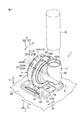
- FIG. 1 is a perspective view of a fixture according to an embodiment of the present invention.
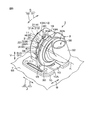
- FIG. 2 is an exploded perspective view of the fixture.
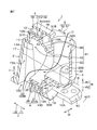
- FIG. 3 is a bottom view of the main body member constituting the fixture.
- FIG. 4 is a side view of the article support member constituting the fixture.
- FIG. 5 is a perspective view of the fixture during assembly.
- FIG. 6 is a perspective view of the fixture during assembly.
- FIG. 7 is a schematic perspective view showing a longitudinal section with a part of the fixture of FIG. 1 cut away.
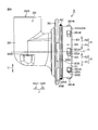
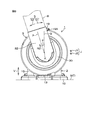
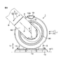
- FIG. 8 is a front view of the completed fixture.
- FIG. 9 is a front view of the completed fixture.
- FIG. 10 is a front view of the completed fixture.
- FIG. 1 is a perspective view of a fixture according to an embodiment of the present invention.
- the fixture 1 is for attaching the article B to the attachment target T.
- An example of the article B is a signal indicator lamp used at a factory manufacturing site or the like.
- An example of the attachment target T in this case is an apparatus such as a machine tool or a measuring machine installed at the manufacturing site.
- a flag, a fishing rod, an antenna, and the like can be given.
- the posture of the fixture 1 at the time of use can be set to an arbitrary posture such as a standing posture or a tilted posture according to use conditions.
- the fixture 1 in the standing posture in FIG. 1 will be described below as a reference. Therefore, in FIG. 1, the upper side of the paper surface is regarded as the upper side of the fixture 1, and the lower side of the paper surface is regarded as the lower side of the fixture 1.
- the fixture 1 includes a main body member 2, an article support member 3, and an engagement mechanism 4.
- Each of the main body member 2 and the article support member 3 is, for example, an integrally molded product made of resin.
- the material of the fixture 1 is not limited to resin.
- the main body member 2 integrally includes a mounting portion 10, a substantially disc-shaped first main wall 11, and a substantially annular first projecting wall 12 coaxial with the first main wall 11.
- the article support member 3 integrally includes a substantially disc-shaped second main wall 30, a substantially annular second projecting wall 31 coaxial with the second main wall 30, and a support portion 32.
- the central axis is referred to as a predetermined rotation axis K, and the direction along the rotation axis K is referred to as an axis direction J.
- the axial direction J is orthogonal to the up-down direction V in FIG.
- a direction orthogonal to both the axial direction J and the vertical direction V is referred to as a width direction W.
- FIG. 2 is an exploded perspective view of the fixture 1.
- the central axis of the first overhanging wall 12 and the second overhanging wall 31 coincides with the rotation axis K, and the main body member 2 and the article support member 3 face each other along the axial direction J.
- the state is shown.
- the axial direction J one side away from the body member 2 toward the article support member 3 in FIG. 2 is referred to as the near side J1, and the other side away from the article support member 3 and toward the body member 2 in FIG. It is called J2.
- the circumferential direction S around the rotation axis K one side is referred to as a first rotation direction S1, and the opposite side to the first rotation direction S1 is referred to as a second rotation direction S2.
- the first rotation direction S1 corresponds to a clockwise direction when the main body member 2 is viewed from the front side J1 in FIG. 2, and the second rotation direction S2 corresponds to a counterclockwise direction.
- a radial direction centered on the rotation axis K is referred to as a radial direction R.
- a direction approaching the rotation axis K is referred to as a radial inner side R1
- a direction away from the rotation axis K is referred to as a radial outer side R2.
- the attachment portion 10 is formed in a substantially rectangular plate shape along the axial direction J, and the thickness direction thereof coincides with the vertical direction V.
- a recess 10A that is recessed from the approximate center in the width direction W of the one side to the back side J2 is formed on one side J1.
- the concave portion 10A penetrates a part of the attachment portion 10 in the thickness direction.
- a lock member 13 formed in a small piece shape that is thinner in the vertical direction V than the mounting portion 10 is provided.
- a claw portion 13A that protrudes upward and that is formed on a ridge extending in the width direction W is integrally provided at the end of the back side J2 on the upper surface of the lock member 13.
- a through hole 13B that penetrates the lock member 13 in the vertical direction V and a convex portion 13C that protrudes upward are formed on the front side J1 of the upper surface of the lock member 13 from the claw portion 13A.
- a connecting portion 13 ⁇ / b> D extending integrally to the back side J ⁇ b> 2 while meandering in an S shape is integrally provided at the end of the back side J ⁇ b> 2 of the lock member 13.
- the connecting portion 13D is connected from the front side J1 to the section screen 10B that partitions the concave portion 10A from the back side J2 in the mounting portion 10 (see FIG. 3).
- the lock member 13 is supported by the mounting portion 10 and is elastically deformable in the vertical direction V around the connecting portion 13D.
- a plurality of insertion holes 10 ⁇ / b> C penetrating the attachment portion 10 in the vertical direction V are formed on both sides of the recess 10 ⁇ / b> A in the width direction W in the attachment portion 10.
- a pair of leg portions 15 are integrally provided at a position avoiding the insertion hole 10 ⁇ / b> C on the upper surface of the attachment portion 10.
- One leg portion 15 is disposed on each outer side of the concave portion 10 ⁇ / b> A in the width direction W, and protrudes upward from the upper surface of the attachment portion 10.
- a rib 16 extending in the axial direction J is integrally provided at the lower end of each leg portion 15 on the side opposite to the concave portion 10A side.
- the rib 16 has at least a role of reinforcing a connecting portion between the leg portion 15 and the attachment portion 10.
- a hollow extending portion 17 extending upward is integrally provided on the back surface J2 of the upper surface of the mounting portion 10 with respect to the concave portion 10A.
- An opening 10D that exposes the hollow portion 17A of the extending portion 17 to the lower side is formed on the lower surface of the mounting portion 10 (see FIG. 3).
- the first main wall 11 is formed in a substantially disc shape having a plate thickness direction coinciding with the axial direction J.
- the first main wall 11 is connected to the extending portion 17 from the front side J1.
- a substantially central portion of the first main wall 11 in the width direction W is recessed to the back side J2 along the vertical direction V, and the hollow portion 17A of the extending portion 17 is exposed to the front side J1 inside the recess.
- An exposed hole 11A is formed.
- the first projecting wall 12 is formed in a substantially annular shape projecting from the entire area in the circumferential direction S to the front side J1 at the outer peripheral edge of the first main wall 11, and is arranged coaxially with the first main wall 11.
- the main body member 2 is formed with a substantially cylindrical first internal space 18 surrounded by the first main wall 11 and the first overhanging wall 12 and opened to the front side J1.
- the end portion of the near side J1 in the lower region of the outer peripheral surface 12A of the first overhanging wall 12 is connected to the upper end portions of the pair of leg portions 15 of the attachment portion 10 from above.
- An arm portion 19 is integrally provided at the upper end portion of the outer peripheral surface 12A.
- the arm portion 19 extends from the upper end portion of the outer peripheral surface 12A along the axial direction J to the near side J1.
- the end portion of the front side J1 in the arm portion 19 is a restricting portion 19A bent downward, and this restricting portion 19A faces the first internal space 18 from the near side J1.
- a first fitting surface 20 having an arcuate surface shape (cylindrical surface shape in this embodiment) around the rotation axis K is provided in the entire region in the circumferential direction S. ing.
- a first engagement portion 21 is integrally provided on the first fitting surface 20.
- a plurality of the first engaging portions 21 are provided at substantially equal intervals in the circumferential direction S.
- Each first engagement portion 21 extends from the end of the first protrusion 21A in the first rotation direction S1 to the inner side J2 in the axial direction J.
- the first protrusion 21A extends along the circumferential direction S.
- the second protrusion 21B connected to the first main wall 11 in an integrated manner. Therefore, each first engaging portion 21 is formed in a substantially L shape when viewed from the radially inner side R1.
- the portion between the first engaging portions 21 adjacent in the circumferential direction S on the first fitting surface 20 constitutes one engaging groove 22.
- Each of the engagement grooves 22 includes a first groove 22A that linearly extends from the edge on the near side J1 to the back side J2 in the first fitting surface 20, and a first time from the end on the back side J2 in the first groove 22A.
- a second groove 22B linearly extending in the moving direction S1.
- a ride-over portion 23 is provided at a position deviated in the first rotation direction S ⁇ b> 1 in the second groove portion 22 ⁇ / b> B of the engagement groove 22 at the lower end (6 o'clock position away from the arm portion 19).
- the climbing part 23 is a protrusion that protrudes radially inward R1 and extends in the axial direction J and crosses the second groove part 22B.
- the second main wall 30 is formed in a substantially disc shape having a plate thickness direction coinciding with the axial direction J.
- a part of the outer peripheral edge of the article support member 3, specifically, the upper end portion of the outer peripheral edge of the second main wall 30 in FIG. 2, is recessed toward the radially inner side R 1, and the concave portion 30 A penetrates the upper end portion in the axial direction J. Is provided. Referring to FIG.
- a positioning groove 30 ⁇ / b> B that is recessed toward the front side J ⁇ b> 1 and extends in the circumferential direction S is formed on the outer peripheral edge of the side surface of the back side J ⁇ b> 2 in the second main wall 30.
- a plurality of positioning grooves 30 ⁇ / b> B are provided at intervals in the circumferential direction S.
- the dimension in the circumferential direction S of each positioning groove 30B is substantially equal to the circumferential dimension of the claw portion 13A of the lock member 13.
- Each positioning groove 30 ⁇ / b> B may be recessed partway along the second main wall 30 in the axial direction J, or may penetrate the second main wall 30 in the axial direction J.
- the plurality of positioning grooves 30B may be distributed and arranged in the entire circumferential direction S on the outer peripheral edge of the second main wall 30, but in this embodiment, the four positioning grooves 30B include the second main wall. 30 at the outer peripheral edge of the lower side (6 o'clock position side 180 degrees away from the recess 30A).
- the second projecting wall 31 is formed in a substantially annular shape projecting from the portion on the radially inner side R1 from the outer peripheral edge of the second main wall 30 to the back side J2, and is arranged coaxially with the second main wall 30.
- the article support member 3 is formed with a substantially cylindrical second internal space 33 that is surrounded by the second main wall 30 and the second overhanging wall 31 and opened to the back side J2.
- a second fitting surface 34 having an arc surface shape (cylindrical surface shape in this embodiment) around the rotation axis K is provided in the entire region in the circumferential direction S. Yes.
- a second engagement portion 35 is integrally provided on the second fitting surface 34.
- the second engaging portion 35 is a protrusion protruding from the second fitting surface 34 to the radially outer side R2, and a plurality of the second engaging portions 35 are provided at substantially equal intervals in the circumferential direction S.
- the same number of second engaging portions 35 are provided at positions corresponding to the first engaging portions 21 in the circumferential direction S.
- a notch 35 ⁇ / b> A that extends in the axial direction J and cuts the surface of the radially outer side R ⁇ b> 2 in the second engaging portion 35 is formed at a position deviated in the first rotation direction S ⁇ b> 1. Has been.
- notches 35A are formed only in the four second engaging portions 35 that are in the same position as the four positioning grooves 30B one by one in the circumferential direction S.
- a groove 31 ⁇ / b> B extending along the circumferential direction S is formed at the end portion J ⁇ b> 1 nearer the second fitting surface 34 on the outer peripheral surface 31 ⁇ / b> A of the second overhanging wall 31.
- the support portion 32 is formed in a circular tube shape that extends from the approximate center of the second main wall 30 to the near side J1 and then bends radially outward R2.
- a portion of the support portion 32 that extends toward the front side J ⁇ b> 1 is disposed coaxially with the second main wall 30.
- a third internal space 36 is formed in the support portion 32 as a hollow portion. The third internal space 36 communicates with the second internal space 33 from the front side J1.
- An opening 32A that exposes the third inner space 36 to the radially outer side R2 is formed at the end portion of the support portion 32 that extends to the radially outer side R2.
- the opening 32A is located at the same position as the recess 30A of the second main wall 30 in the circumferential direction S, and a part of the article B is inserted into the opening 32A from the radially outer side R2 (see FIG. 2).
- the support part 32 is fixed to the article B by assembling the fastening member (not shown) such as a bolt inserted through the insertion hole 32 ⁇ / b> B formed in the bent part of the support part 32 to the article B.
- a ring-shaped packing (not shown) may be fitted into the opening 32A.
- the gap between the support portion 32 and the article B in the opening 32A is closed by the packing, water in the gap can be prevented.
- the gap between the fastening member inserted into the insertion hole 32B and the support portion 32 may be closed by another packing (not shown).
- the engagement mechanism 4 includes a first engagement portion 21 of the main body member 2 and a second engagement portion 35 of the article support member 3.
- the assembly procedure of the fixture 1 is demonstrated and the role of the engagement mechanism 4 is also demonstrated in that case.
- the operator attaches the main body member 2 to the attachment surface M of the attachment target T.
- a rubber waterproof sheet (not shown) is interposed between the attachment part 10 and the attachment surface M of the main body member 2, for example.
- the waterproof sheet prevents water from entering the opening 10D (see FIG. 3) of the mounting portion 10 from the gap between the mounting portion 10 and the mounting surface M.
- one fastening member such as a bolt is inserted into each insertion hole 10 ⁇ / b> C of the attachment portion 10 and assembled to the attachment target T.
- the attachment part 10 is attached with respect to the attachment object T, and the whole main body member 2 is fixed to the attachment object T.
- the operator places the article support member 3 so as to face the main body member 2 from the front side J1.
- the second overhanging wall 31 is located on the back side J ⁇ b> 2 with respect to the support portion 32.
- the operator aligns the center axis of the second overhanging wall 31 with the center axis of the first overhanging wall 12 (that is, the rotation axis K), and the recess 30A of the second main wall 30 is in the circumferential direction S.
- the article support member 3 is aligned with the main body member 2 so as to be aligned with the restricting portion 19 ⁇ / b> A of the main body member 2.
- the operator moves the article support member 3 thus aligned to the back side J2 so as to approach the main body member 2.
- the restricting portion 19 ⁇ / b> A passes through the recess 30 ⁇ / b> A and is disposed on the front side J ⁇ b> 1 with respect to the second main wall 30.
- the portion of the back side J2 in the second overhanging wall 31 of the article support member 3 is inserted into the inside of the first overhanging wall 12 of the main body member 2, and the second fitting surface of the second overhanging wall 31 is inserted.
- At least a part of 34 faces the first fitting surface 20 of the first overhanging wall 12 from the radially inner side R1.
- each second engagement portion 35 of the article support member 3 is formed in each engagement groove 22 of the main body member 2.
- the vehicle enters the first groove 22A and proceeds to the back side J2.
- each second engagement portion 35 comes into contact with the first main wall 11 when it reaches the end of the back side J2 in the first groove portion 22A. I can't proceed.
- the operator rotates the article support member 3 relative to the main body member 2 in the first rotation direction S1 so that the article support member 3 is displaced from the main body member 2 in the first rotation direction S1.
- each 2nd engaging part 35 of the article support member 3 enters the 2nd groove part 22B from the 1st groove part 22A in each engaging groove 22 of the main body member 2, and the inside of the 2nd groove part 22B is 1st time. Proceed in the moving direction S1.
- item support member 3 is 1st of the 1st engaging part 21 of the main body member 2 in the edge part of the 1st rotation direction S1 in the 2nd groove part 22B.
- the protrusion 21A is engaged from the back side J2. Thereby, each 2nd engaging part 35 cannot move relatively with respect to the 1st engaging part 21 regarding the axial direction J.
- each second engagement portion 35 is engaged with the second protrusion 21B of the first engagement portion 21 from the second rotation direction S2, whereby the first engagement portion is related to the first rotation direction S1. The relative movement with respect to 21 is impossible.
- the engagement mechanism 4 having the first engagement portion 21 and the second engagement portion 35 is moved in the axial direction J and the first time by the relative rotation of the article support member 3 in the first rotation direction S1.
- the second engaging portion 35 is engaged with the first engaging portion 21 so as not to move relative to each other in the moving direction S1.
- the fixture 1 can be easily assembled with one touch without using a tool.
- a fastening member such as a bolt is not required for assembly, and the fixture 1 can be constituted by two main parts, ie, the main body member 2 and the article support member 3, so that the number of parts can be reduced.
- the second engaging portion 35 located at the lower end more specifically, the distal end portion 35B (see FIG. 4) closer to the first rotational direction S1 than the notch 35A is directed to the first rotational direction S1.
- the ride-over portion 23 in the second groove portion 22B of the engagement groove 22 located at the lower end gets over the first rotation direction S1 (see FIG. 2).
- the climbing part 23 is fitted into the notch 35 ⁇ / b> A of the second engagement part 35.
- the climbing part 23 maintains the second engagement part 35 in the engagement position with the first engagement part 21 with a predetermined force. Therefore, the engagement between the first engagement portion 21 and the second engagement portion 35 can be maintained so as not to be inadvertently released.
- the tip 35B of the second engagement portion 35 gets over the climbing portion 23 according to the relative rotation of the article support member 3, a click feeling is obtained. With this click feeling, it can be easily grasped that the engagement between the first protruding portion 21A and the second engaging portion 35 is achieved.
- the second engaging portion 35 in which the notch 35A is formed is deleted by removing the portion on the second rotation direction S2 side from the notch 35A, and the second engaging portion 35 is configured only by the tip portion 35B. Also good. In this case, during the relative rotation of the article support member 3, all of the second engaging portions 35 completely get over the climbing portion 23 in the first rotation direction S1.
- FIG. 7 is a schematic perspective view showing a longitudinal section in which the fixture 1 of FIG. 1 is cut along a cut surface extending in the vertical direction V through the rotation axis K and a part thereof is cut away.
- the claw portion 13A of the lock member 13 of the main body member 2 is the same in the circumferential direction S on the second main wall 30 of the article support member 3. It fits into the positioning groove 30B at the position from the radially outer side R2. Therefore, the relative rotation of the article support member 3 with respect to the main body member 2 is restricted. Also by this, the engagement between the first engagement portion 21 and the second engagement portion 35 can be maintained so as not to be inadvertently released.
- the main body member 2 and the article support member 3 are connected so as not to be relatively movable in both the circumferential direction S and the axial direction J.
- the second main wall 30 of the article support member 3 faces the first main wall 11 from the front side J ⁇ b> 1 across the first internal space 18 of the main body member 2, and the article support member 3.
- the second internal space 33 communicates with the first internal space 18.
- the first internal space 18, the second internal space 33, and the third internal space 36 of the support portion 32 of the article support member 3 constitute one wide accommodating space 41 inside the fixture 1.
- a cable C for supplying electric power or transmitting a control signal to the article B (see FIG.
- the support portion 32 supported by the support portion 32 is a hollow in the opening 10D of the attachment portion 10 of the main body member 2 and the extension portion 17. It is accommodated in the accommodation space 41 through the portion 17A and connected to the article B. Thus, even the thick cable C can be reliably accommodated using the accommodation space 41.
- the attachment of the article B to the support portion 32 and the connection of the cable C to the article B may be performed before the main body member 2 and the article support member 3 are coupled.
- a sealing member 42 made of an O-ring or the like is fitted in the groove 31B of the second overhanging wall 31 of the article support member 3.
- the sealing member 42 seals the gap in the radial direction R between the first projecting wall 12 and the second projecting wall 31 of the main body member 2. Therefore, it is possible to prevent water from entering the accommodation space 41 from the gap with a simple configuration using the sealing member 42.
- the acute crossing angle between the center axis P of the portion extending to the radially outer side R ⁇ b> 2 in the support portion 32 and the reference line Q extending in the vertical direction V through the rotation axis K is the main body This is the relative rotation angle ⁇ around the rotation axis K of the article support member 3 with respect to the member 2.
- the relative rotation angle ⁇ is also an inclination angle with respect to the reference line Q of the article B supported by the support portion 32.
- the article support member 3 can be attached to the main body member 2 at at least two attachment positions in the circumferential direction S by changing the relative rotation angle ⁇ . Therefore, the engagement mechanism 4 is configured such that the first engagement portion 21 and the second engagement portion 35 can be engaged at a plurality of mounting positions having different relative rotation angles ⁇ .
- the operator elastically deforms the lock member 13 downward, and the claw portion 13 ⁇ / b> A of the lock member 13 is positioned in the positioning groove of the article support member 3. It removes from 30B to radial direction outer side R2 (refer FIG. 7). Thereby, the restriction
- the engagement mechanism 4 the engagement between the second engagement portions 35 of the article support member 3 and the first engagement portions 21 of the main body member 2 is released. And the article support member 3 can be moved relative to each other for alignment.
- the portion of the back side J2 in the second overhanging wall 31 continues.
- the inner side of the first overhanging wall 12 is fitted from the front side J1, and the rear side J2 portion of the second fitting surface 34 continues to face the first fitting surface 20 from the radially inner side R1.
- the restricting portion 19 ⁇ / b> A of the main body member 2 contacts the outer peripheral edge of the second main wall 30 of the article support member 3 from the near side J ⁇ b> 1 in the axial direction J to temporarily hold the article support member 3. Therefore, the article supporting member 3 is restricted from being detached from the main body member 2 to the near side J1. For this reason, it is possible to prevent the article support member 3 from moving to the near side J1 during the change of the relative rotation angle ⁇ and inadvertently detaching and falling to the near side J1 together with the article B. Thereby, the operator can easily rotate the article support member 3 relative to the main body member 2 and change the relative rotation angle ⁇ .
- the restricting portion 19A can pass through the recessed portion 30A. Therefore, the article supporting member 3 is detached from the main body member 2 to the near side J1, and the fixture 1 is removed. By disassembling, the wiring of the cable C and the maintenance of the fixture 1 can be easily performed.
- the operator holds the article support member 3 in the circumferential direction S by a desired distance from the main body member 2.
- the article support member 3 is pushed into the back side J2 to be relatively rotated in the first rotation direction S1.
- the lock member 13 of the main body member 2 is elastically deformed, and the claw portion 13A of the lock member 13 is
- the second main wall 30 of the article support member 3 is automatically fitted into the positioning groove 30B at the same position in the circumferential direction S (see FIG. 7). Thereby, the assembly of the fixture 1 in which the relative rotation angle ⁇ is changed is completed.
- the relative rotation angle ⁇ is set to at least two or more as shown in FIGS. Can be changed to a value.
- the relative rotation angle ⁇ is the same number as the positioning grooves 30B formed in the article support member 3 (here, four), and has a plurality of steps (here, for example, ⁇ 45 degrees, 0 degrees, 45 degrees, and 90 degrees). 4 levels).
- the device to be attached T is carried into the manufacturing site, if the support part 32 and the article B are tilted so that the relative rotation angle ⁇ is close to 90 degrees, the article B is placed around the carry-in entrance. You can prevent it from hitting.
- the attachment surface M is provided on the side surface of the attachment target T, the relative rotation angle is fixed in a state in which the attachment portion 10 is fixed along the attachment surface M with the rotation axis K facing the horizontal direction.
- the support portion 32 and the article B may be arranged vertically along the attachment surface M so that ⁇ is close to 90 degrees.
- the article B is a signal indicator lamp
- the signal indicator lamp when the signal indicator lamp is attached to each of a plurality of devices arranged along the passage at the manufacturing site via the fixture 1, it is viewed from the end of the passage.
- the relative rotation angle ⁇ may be changed for each device so that all the signal indicators are in the field of view of the viewer.
- the second overhanging wall 31 of the article support member 3 is fitted from the front side J1 with respect to the first overhanging wall 12 of the main body member 2 (see FIG. 7).
- One outer wall 12 may be externally fitted from the front side J1.
- the first fitting surface 20 provided with the first engaging portion 21 is the outer peripheral surface 12 ⁇ / b> A of the first overhanging wall 12.
- the second fitting surface 34 provided with the second engaging portion 35 is formed on the inner peripheral surface 31C (see FIG. 7) of the second overhanging wall 31.
- the second overhanging wall 31 is fitted in or out of the first overhanging wall 12, and then the article support member 3 is rotated relative to the main body member 2 in the first rotation direction S1.
- the fixture 1 can be easily assembled by a simple operation of making it happen.
- first fitting surface 20 may not be provided in the entire area of the first overhanging wall 12 in the circumferential direction S, and similarly, the second fitting surface 34 is formed in the second overhanging wall in the circumferential direction S. It may not be provided in the whole area of 31.
- each of the first projecting wall 12 and the second projecting wall 31 may not be an annular shape having a perfect circular cross section, and may be an annular shape having a substantially circular or semicircular cross section. Good.
- first engaging portion 21 and the second engaging portion 35 are provided, but it is sufficient that at least one of them is provided. Therefore, for example, there may be a configuration in which only one first engagement portion 21 is provided and a plurality of second engagement portions 35 are provided, or a configuration opposite to this.
- the lock member 13 for restricting the relative rotation of the article support member 3 may be provided not only in the main body member 2 but also in both the main body member 2 and the article support member 3. It may be provided only on the member 3.
- these lock members 13 regulate relative rotation of the article support member 3 by engaging with each other.
- the lock member 13 restricts relative rotation of the article support member 3 by being caught by any part of the main body member 2.
- the restricting portion 19A described above may be provided not only on the arm portion 19 but also on the lock member 13, for example.
- the restricting portion 19A comes into contact with the second main wall 30 of the article support member 3 from above and below, it is possible to reliably restrict the article support member 3 from being detached from the main body member 2 to the front side J1.
- a chamfer 43 for preventing a catch between the main body member 2 and the article support member 3 when the fixture 1 is assembled is appropriately provided at a necessary position. (See FIGS. 2 and 4).
- the chamfer 43 is provided over the entire region in the circumferential direction S in the region on the near side J1 of the inner peripheral surface 12B of the first overhanging wall 12 relative to the first fitting surface 20 (see FIG. 2). .
- Sealing member B ... Article C ... Cable J ... Axial direction J1 ... Front side J2 ... Back side K ... Rotation axis S ... Circumferential direction S1 ... First rotation direction S2 ... Second rotation direction T ... Attachment object ⁇ ... Relative rotation angle
Landscapes
- Engineering & Computer Science (AREA)
- General Engineering & Computer Science (AREA)
- Architecture (AREA)
- Mechanical Engineering (AREA)
- Theoretical Computer Science (AREA)
- Physics & Mathematics (AREA)
- General Physics & Mathematics (AREA)
- Civil Engineering (AREA)
- Structural Engineering (AREA)
- Snaps, Bayonet Connections, Set Pins, And Snap Rings (AREA)
- Connection Of Plates (AREA)
- Mutual Connection Of Rods And Tubes (AREA)
- Gasket Seals (AREA)
Abstract
取付具(1)は、取付対象(T)に取り付けられる本体部材(2)と、物品(B)を支持する物品支持部材(3)と、係合機構(4)とを含む。本体部材(2)は、円弧面状の第1嵌め合い面(20)を有する。物品支持部材(3)は、第1嵌め合い面(20)に対向した円弧面状の第2嵌め合い面(34)を有する。係合機構(4)は、第1嵌め合い面(20)に設けられた第1係合部(21)と、第2嵌め合い面(34)に設けられた第2係合部(35)とを有する。係合機構(4)は、回動軸線(K)まわりの第1回動方向(S1)への本体部材(2)に対する物品支持部材(3)の相対回動によって、回動軸線(K)に沿う軸線方向(J)および第1回動方向(S1)のそれぞれに関して第2係合部(35)を第1係合部(21)に対して相対移動不能に係合させる。係合機構(4)は、第1回動方向(S1)とは反対の第2回動方向(S2)への本体部材(2)に対する物品支持部材(3)の相対回動によって第1係合部(21)と第2係合部(35)との係合を解除させる。
Description
この発明は、物品を取付対象に取り付けるための取付具に関する。
特許文献1は、信号表示灯を取付対象に角度調整可能に取り付ける角度固定装置を開示している。角度固定装置は、取付対象に固定された第1の部材と、信号表示灯に固定された第2の部材とを含む。第1の部材には、第1の環状歯列が形成されている。第2の部材には、第2の環状歯列と、第2の環状歯列に沿って湾曲して延びた複数の挿通孔とが形成されている。第1の環状歯列と第2の環状歯列とは、所定の軸線を中心とする複数の相対回転位置で噛合可能である。各挿通孔には、前記軸線に沿う方向からボルトが1つずつ挿通されて、第1の部材のねじ孔に組み付けられ、それによって、いずれかの相対回転位置で第1および第2の環状歯列が噛合した状態で、第1および第2の部材が互いに固定されている。
ボルトが緩められた状態において、第1の部材と第2の部材とを前記軸線に沿って互いに遠ざかるように相対移動させると、第1の環状歯列と第2の環状歯列との噛み合いが外れる。これにより、第1の部材と第2の部材とは、前記軸線まわりに互いに相対回転できるようになるので、信号表示灯の取付角度を調整することができる。取付角度の調整後に、第1の部材と第2の部材とを互いに接近させて第1の環状歯列と第2の環状歯列とを噛み合わせる。その後、第1の部材と第2の部材とをボルトによって互いに固定すると、調整された取付角度が固定される。
特許文献1の角度固定装置は、第1の部材と第2の部材との固定のために複数のボルトを必要とするので、部品点数が多い。また、角度固定装置を組み立てるために各ボルトを締める作業が必要であり、さらに、この作業のために工具が必要である。
そこで、この発明は、組立が容易であり、部品点数の削減を図れる取付具を提供する。
この発明は、所定の回動軸線(K)を中心とした円弧面状の第1嵌め合い面(20)と、取付対象(T)に対して取り付けられる取付部(10)とを有する本体部材(2)と、前記第1嵌め合い面に対向し、前記回動軸線を中心とした円弧面状の第2嵌め合い面(34)と、物品(B)を支持する支持部(32)とを有する物品支持部材(3)と、前記第1嵌め合い面に設けられた第1係合部(21)と、前記第2嵌め合い面に設けられた第2係合部(35)とを有し、前記回動軸線まわりの第1回動方向(S1)への前記本体部材に対する前記物品支持部材の相対回動によって、前記回動軸線に沿う軸線方向(J)および前記第1回動方向のそれぞれに関して前記第2係合部を前記第1係合部に対して相対移動不能に係合させ、前記回動軸線まわりにおける前記第1回動方向とは反対の第2回動方向(S2)への前記本体部材に対する前記物品支持部材の相対回動によって前記第1係合部と前記第2係合部との係合を解除させる係合機構(4)と、を含む取付具(1)を提供する。
なお、この項において、括弧内の英数字は、後述の実施形態における対応構成要素の参照符号を示すが、これらの参考符号により発明を限定する趣旨ではない。
この構成によれば、回動軸線まわりの第1回動方向への本体部材に対する物品支持部材の相対回動によって、軸線方向および第1回動方向のそれぞれに関して、物品支持部材の第2嵌め合い面における第2係合部が、本体部材の第1嵌め合い面における第1係合部に対して相対移動不能に係合する。これにより、工具を用いなくても、物品支持部材を第1回動方向へ相対回動させるという簡単な操作によって、取付具を容易に組み立てることができる。また、取付具では、組み立てのためにボルト等の締結部材が不要なので、部品点数の削減を図れる。
一方、回動軸線まわりにおける第1回動方向とは反対の第2回動方向への本体部材に対する物品支持部材の相対回動によって第1係合部と第2係合部との係合が解除される。これにより、第1係合部と第2係合部との係合が解除された状態では、本体部材と物品支持部材とを互いの位置合わせのために相対移動させることができる。
一方、回動軸線まわりにおける第1回動方向とは反対の第2回動方向への本体部材に対する物品支持部材の相対回動によって第1係合部と第2係合部との係合が解除される。これにより、第1係合部と第2係合部との係合が解除された状態では、本体部材と物品支持部材とを互いの位置合わせのために相対移動させることができる。
この発明の一実施形態では、前記第1係合部および前記第2係合部のうちの少なくとも一方が、前記回動軸線まわりの周方向(S)に間隔を開けて複数個設けられており、前記係合機構は、前記本体部材に対する前記物品支持部材の前記回動軸線まわりの相対回動角(θ)が異なる少なくとも2つの装着位置において、前記第1係合部と前記第2係合部とが係合可能となるように構成されている。
この構成によれば、互いに係合する第1係合部と前記第2係合部とを変更することによって、本体部材に対する物品支持部材の相対回動角を少なくとも2つ以上の値に変更できる。
この発明の一実施形態では、前記第1係合部は、前記周方向に沿って延びる第1突条部(21A)と、前記第1回動方向における前記第1突条部の端部から前記軸線方向に延びる第2突条部(21B)とを含み、前記第2係合部は、前記第2嵌め合い面から突出した突起を含む。
この構成によれば、第2係合部は、第1突条部に係合することによって、軸線方向に関して第1係合部に対して相対移動不能となり、第2突条部に係合することによって、第1回動方向に関して第1係合部に対して相対移動不能となる。これにより、第1係合部と第2係合部との係合が達成される。一方、第2係合部が第1突条部から第2回動方向へ外れると、第1係合部と第2係合部との係合の解除が達成される。
この発明の一実施形態では、取付具は、前記第1嵌め合い面に設けられ、前記第1回動方向への前記物品支持部材の相対回動の際に前記第2係合部の少なくとも一部(35B)によって乗り越えられ、所定の力によって前記第2係合部を前記第1係合部との係合位置に維持する乗り越え部(23)をさらに含む。
この構成によれば、第2係合部の少なくとも一部が第1嵌め合い面の乗り越え部を乗り越えたときに、クリック感が得られる。このクリック感によって、第1係合部と第2係合部との係合が達成されたことを容易に把握できる。そして、第2係合部の少なくとも一部が第1嵌め合い面の乗り越え部を乗り越えた状態では、乗り越え部が、第2係合部を動かないように維持する。そのため、第1係合部と第2係合部との係合を、不用意に解除されないように維持することができる。ただし、所定の力を上回る力で第2回動方向へ物品支持部材を相対回動させれば、第2係合部が乗り越え部から外れるので、第1係合部と第2係合部との係合を必要に応じて解除することができる。
この発明の一実施形態では、取付具は、前記本体部材および前記物品支持部材の少なくとも一方に設けられ、前記第1係合部と前記第2係合部とが係合した状態で、前記本体部材に対する前記回動軸線まわりの前記物品支持部材の相対回動を規制するロック部材(13)をさらに含む。
この構成によれば、ロック部材が本体部材に対する物品支持部材の相対回動を規制するので、第1係合部と第2係合部との係合を、不用意に解除されないように維持することができる。
この発明の一実施形態では、前記ロック部材は、前記物品支持部材の相対回動の規制を解除するために弾性変形可能である。
この構成によれば、必要に応じて、ロック部材を弾性変形させて物品支持部材の相対回動の規制を解除すれば、物品支持部材を相対回動させて第1係合部と第2係合部との係合を解除することができる。
この発明の一実施形態では、取付具は、前記本体部材に設けられ、前記第1係合部と前記第2係合部との係合が解除された状態の前記物品支持部材に対して前記軸線方向から当接して、前記物品支持部材が前記本体部材から離脱することを規制する規制部(19A)をさらに含み、前記物品支持部材の外周縁の一部に、前記規制部が通り抜け可能な凹部(30A)が設けられている。なお、ここでの「物品支持部材の離脱」とは、第2嵌め合い面が第1嵌め合い面に対向しなくなるまで物品支持部材が本体部材から軸線方向へ離れていて、物品支持部材を本体部材に接近させない限り、どの方向へ物品支持部材を動かしても物品支持部材が本体部材に接触しない自由な状態にあることをいう。
この構成によれば、第1係合部と第2係合部との係合が解除された状態では、本体部材の規制部が物品支持部材に対して軸線方向から当接するので、物品支持部材が軸線方向へ移動して本体部材から不用意に離脱することを防止できる。これにより、第1係合部と第2係合部との係合が解除された状態において、物品支持部材を本体部材に対して軸線方向に位置決めした状態で容易に相対回動させることができる。一方で、必要に応じて、規制部を物品支持部材の外周縁の凹部に位置合わせすれば、規制部が凹部を軸線方向へ通り抜けることによって、物品支持部材を本体部材から離脱させることができる。
この発明の一実施形態では、前記本体部材は、第1主壁(11)と、前記軸線方向における一方側(J1)へ前記第1主壁から張り出して前記第1嵌め合い面が設けられた第1張出壁(12)とを有し、前記本体部材には、前記第1主壁および前記第1張出壁によって囲まれて前記一方側へ開放された第1内部空間(18)が形成され、前記物品支持部材は、前記第1内部空間を挟んで前記一方側から前記第1主壁に対向した第2主壁(30)と、前記第2主壁から前記軸線方向における他方側(J2)へ張り出して前記第1張出壁に対して前記一方側から内嵌または外嵌されて前記第2嵌め合い面が設けられた第2張出壁(31)とを有し、前記物品支持部材には、前記第2主壁および前記第2張出壁によって囲まれて前記第1内部空間に連通した第2内部空間(33)が形成されている。
この構成によれば、物品支持部材において第2嵌め合い面が設けられた第2張出壁を、本体部材において第1嵌め合い面が設けられた第1張出壁に対して内嵌または外嵌し、その後、物品支持部材を本体部材に対して第1回動方向へ相対回動させるという簡単な操作によって、取付具を容易に組み立てることができる。
この発明の一実施形態では、前記支持部には、前記第2内部空間に連通した第3内部空間(36)が形成され、前記第1内部空間、前記第2内部空間および前記第3内部空間は、物品に接続されるケーブル(C)を収容するための収容空間(41)を構成している。
この構成によれば、収容空間を利用して、ケーブルを収容することができる。
この発明の一実施形態では、取付具は、前記第1張出壁と前記第2張出壁との隙間を封止している封止部材(42)をさらに含む。
この構成によれば、第1張出壁と第2張出壁との隙間から収容空間への浸水を、封止部材によって防止できる。
以下には、図面を参照して、この発明の一実施形態について具体的に説明する。図1は、この発明の一実施形態に係る取付具の斜視図である。取付具1は、物品Bを取付対象Tに取り付けるためのものである。物品Bの一例は、工場の製造現場等で使用される信号表示灯である。この場合の取付対象Tの例は、製造現場に設置された工作機械や測定機等の装置である。物品Bの別の例として、旗や釣竿やアンテナ等を挙げることができる。
使用時における取付具1の姿勢は、使用条件に応じて起立姿勢や傾倒姿勢等の任意の姿勢に設定できるが、以下では、便宜上、図1における起立姿勢の取付具1を基準として説明する。そのため、図1において、紙面の上側を取付具1の上側とみなし、紙面の下側を取付具1の下側とみなす。取付具1は、本体部材2と、物品支持部材3と、係合機構4とを含む。本体部材2および物品支持部材3のそれぞれは、たとえば樹脂製の一体成形品である。もちろん、取付具1の材料は樹脂に限定されない。
本体部材2は、取付部10と、略円板形状の第1主壁11と、第1主壁11と同軸状の略円環状の第1張出壁12とを一体的に有する。物品支持部材3は、略円板形状の第2主壁30と、第2主壁30と同軸状の略円環状の第2張出壁31と、支持部32とを一体的に有する。第1張出壁12と第2張出壁31とを、互いの中心軸線を一致させた状態で、対向させて嵌め合わせてから当該中心軸線まわりに相対回動させると、本体部材2に物品支持部材3が装着されて取付具1が完成する。以下では、当該中心軸線を所定の回動軸線Kといい、回動軸線Kに沿う方向を軸線方向Jという。軸線方向Jは、図1の上下方向Vと直交している。図1において軸線方向Jおよび上下方向Vの両方に直交する方向を幅方向Wという。
図2は、取付具1の分解斜視図である。図2では、第1張出壁12および第2張出壁31の互いの中心軸線が回動軸線Kに一致して本体部材2と物品支持部材3とが軸線方向Jに沿って対向している状態が示されている。軸線方向Jのうち、図2において本体部材2から離れて物品支持部材3へ向かう一方側を手前側J1といい、図2において物品支持部材3から離れて本体部材2へ向かう他方側を奥側J2という。回動軸線Kまわりの周方向Sのうち、一方側を第1回動方向S1といい、第1回動方向S1とは反対側を第2回動方向S2という。第1回動方向S1は、図2における手前側J1から本体部材2を見た場合における時計回りの方向に相当し、第2回動方向S2は、反時計回りの方向に相当する。また、回動軸線Kを中心とする径方向を径方向Rという。径方向Rのうち、回動軸線Kに近付く方向を径方向内側R1といい、回動軸線Kから離れる方向を径方向外側R2という。
まず、本体部材2の取付部10、第1主壁11および第1張出壁12について説明する。取付部10は、軸線方向Jに沿った略矩形の板状に形成されており、その板厚方向は、上下方向Vと一致している。取付部10において略矩形の輪郭を構成する四辺のうち、手前側J1の一辺には、当該一辺の幅方向Wの略中央から奥側J2へ窪む凹部10Aが形成されている。凹部10Aは、取付部10の一部を板厚方向において貫通している。凹部10A内には、取付部10よりも上下方向Vに薄い小片状に形成されたロック部材13が設けられている。
ロック部材13の上面において奥側J2の端部には、上側へ突出し、かつ幅方向Wに延びる突条に形成された爪部13Aが一体的に設けられている。ロック部材13の上面において爪部13Aよりも手前側J1には、ロック部材13を上下方向Vに貫通した貫通孔13Bと、上側へ突出した凸部13Cとが形成されている。図3に最もよく表われているように、ロック部材13の奥側J2の端部には、例えばS字に蛇行しながら奥側J2へ延びた連結部13Dが一体的に設けられている。連結部13Dは、取付部10において凹部10Aを奥側J2から区画する区画面10Bに対して手前側J1から連結されている(図3参照)。ロック部材13は、取付部10によって支持されており、連結部13Dを中心として上下方向Vに弾性変形可能である。
取付部10において幅方向Wにおける凹部10Aの両側には、取付部10を上下方向Vに貫通した複数の挿通孔10Cが形成されている。取付部10の上面において挿通孔10Cを避けた位置には、一対の脚部15が一体的に設けられている。脚部15は、幅方向Wにおける凹部10Aの両外側に1つずつ配置され、取付部10の上面から上側へ突出している。各脚部15の下端部において凹部10A側とは反対側には、軸線方向Jに延びるリブ16が一体的に設けられている。リブ16は、脚部15と取付部10との連結部分を補強する役割を少なくとも有する。
取付部10の上面において凹部10Aよりも奥側J2には、上側へ延びた中空の延設部17が一体的に設けられている。取付部10の下面には、延設部17の中空部分17Aを下側へ露出させる開口10Dが形成されている(図3参照)。
第1主壁11は、軸線方向Jに一致した板厚方向を有する略円板状に形成されている。第1主壁11は、手前側J1から延設部17に接続されている。幅方向Wにおける第1主壁11の略中央部は、上下方向Vに沿って奥側J2に窪んでおり、その窪みの内部には、延設部17の中空部分17Aを手前側J1へ露出させた露出穴11Aが形成されている。
第1張出壁12は、第1主壁11の外周縁において周方向Sにおける全域から手前側J1へ張り出した略円環状に形成され、第1主壁11と同軸状に配置されている。本体部材2には、第1主壁11および第1張出壁12によって囲まれて手前側J1へ開放された略円柱状の第1内部空間18が形成されている。第1張出壁12の外周面12Aの下側領域における手前側J1の端部は、取付部10の一対の脚部15の上端部に対して上側から接続されている。外周面12Aの上端部には、アーム部19が一体的に設けられている。アーム部19は、外周面12Aの上端部から軸線方向Jに沿って手前側J1へ延びている。アーム部19において手前側J1の端部は、下側へ折り曲げられた規制部19Aであり、この規制部19Aは、第1内部空間18に手前側J1から臨んでいる。
第1張出壁12の内周面12Bにおいて周方向Sにおける全域には、回動軸線Kを中心とした円弧面状(この実施形態では円筒面状)の第1嵌め合い面20が設けられている。第1嵌め合い面20には、第1係合部21が一体的に設けられている。第1係合部21は、周方向Sに略等しい間隔を開けて複数個設けられている。各第1係合部21は、周方向Sに沿って延びる第1突条部21Aと、第1回動方向S1における第1突条部21Aの端部から軸線方向Jの奥側J2に延びて第1主壁11に接続された第2突条部21Bとを一体的に含む。そのため、径方向内側R1から見て、各第1係合部21は、略L字形状に形成されている。
第1嵌め合い面20において周方向Sに隣り合う第1係合部21の間の部分は、1つの係合溝22を構成している。各係合溝22は、第1嵌め合い面20における手前側J1の端縁から奥側J2へ直線的に延びる第1溝部22Aと、第1溝部22Aにおける奥側J2の端部から第1回動方向S1へ直線的に延びる第2溝部22Bとを含む。図2において下端(アーム部19から180度離れた6時位置)にある係合溝22の第2溝部22Bにおいて第1回動方向S1へ偏った位置には、乗り越え部23が設けられている。乗り越え部23は、径方向内側R1へ突出し、かつ軸線方向Jに延びて第2溝部22Bを横切った突条である。
次に、物品支持部材3の第2主壁30、第2張出壁31および支持部32について説明する。第2主壁30は、軸線方向Jに一致した板厚方向を有する略円板状に形成されている。物品支持部材3の外周縁の一部、詳しくは図2における第2主壁30の外周縁の上端部には、径方向内側R1へ窪み、かつ当該上端部を軸線方向Jに貫通した凹部30Aが設けられている。図4を参照して、第2主壁30において奥側J2の側面の外周縁には、手前側J1へ窪み、かつ周方向Sに延びた位置決め溝30Bが形成されている。位置決め溝30Bは、周方向Sに間隔を開けて複数設けられている。各位置決め溝30Bの周方向Sの寸法は、ロック部材13の爪部13Aの周方向寸法とほぼ等しい。各位置決め溝30Bは、軸線方向Jにおける第2主壁30の途中まで窪んでいてもよいし、軸線方向Jにおいて第2主壁30を貫通していてもよい。また、複数の位置決め溝30Bは、第2主壁30の外周縁において周方向Sにおける全域に分散して配置されてもよいが、この実施形態では、4つの位置決め溝30Bが、第2主壁30の外周縁における下側(凹部30Aから180度離れた6時位置側)の領域に偏って配置されている。
第2張出壁31は、第2主壁30の外周縁よりも径方向内側R1の部分から奥側J2へ張り出した略円環状に形成され、第2主壁30と同軸状に配置されている。物品支持部材3には、第2主壁30および第2張出壁31によって囲まれて奥側J2へ開放された略円柱状の第2内部空間33が形成されている。第2張出壁31の外周面31Aにおいて周方向Sにおける全域には、回動軸線Kを中心とした円弧面状(この実施形態では円筒面状)の第2嵌め合い面34が設けられている。
第2嵌め合い面34には、第2係合部35が一体的に設けられている。第2係合部35は、第2嵌め合い面34から径方向外側R2へ突出した突起であり、周方向Sに略等しい間隔を開けて複数個設けられている。この実施形態では、第2係合部35は、周方向Sにおいて第1係合部21に対応する位置に同数設けられている。少なくとも1つの第2係合部35において第1回動方向S1へ偏った位置には、軸線方向Jに延びて第2係合部35における径方向外側R2の表面を切り取った切欠き35Aが形成されている。この実施形態では、周方向Sにおいて4つの位置決め溝30Bと1つずつ同じ位置にある4つの第2係合部35だけに切欠き35Aが形成されている。第2張出壁31の外周面31Aにおいて第2嵌め合い面34よりも手前側J1の端部には、周方向Sに沿って延びる溝31Bが形成されている。
支持部32は、第2主壁30の略中心から手前側J1へ延びた後に径方向外側R2へ屈曲した円管状に形成されている。支持部32において手前側J1へ延びている部分は、第2主壁30と同軸状に配置されている。支持部32には、その中空部分として第3内部空間36が形成されている。第3内部空間36は、第2内部空間33に手前側J1から連通している。支持部32において径方向外側R2へ延びた部分の径方向外側R2の端部には、第3内部空間36を径方向外側R2へ露出させる開口32Aが形成されている。開口32Aは、周方向Sにおいて第2主壁30の凹部30Aと同じ位置にあり、開口32Aには、物品Bの一部が径方向外側R2から挿入される(図2参照)。支持部32の屈曲部に形成された挿通孔32Bから挿通されたボルト等の締結部材(図示せず)が物品Bに組み付けられることによって、支持部32は、物品Bに固定される。なお、開口32Aにリング状のパッキン(図示せず)が嵌め込まれてもよい。開口32Aにおける支持部32と物品Bとの隙間が当該パッキンによって塞がれることによって、当該隙間における浸水を防止できる。同じ目的のために、挿通孔32Bに挿通された締結部材と支持部32との隙間を別のパッキン(図示せず)によって塞いでもよい。
係合機構4は、図2に示すように、本体部材2の第1係合部21と、物品支持部材3の第2係合部35とを有する。以下では、取付具1の組み立ての手順について説明し、その際に、係合機構4の役割についても説明する。
まず、作業者は、本体部材2を、取付対象Tの取付面Mに取り付ける。本体部材2の取付部10と取付面Mとの間には、例えばゴム製の防水シート(図示せず)が介装される。これにより、取付部10と取付面Mとの隙間から取付部10の開口10D(図3参照)への浸水が、防水シートによって防止される。次に、取付部10の各挿通孔10Cに対してボルト等の締結部材が1つずつ挿通され、取付対象Tに組み付けられる。これにより、取付部10が取付対象Tに対して取り付けられ、本体部材2の全体が取付対象Tに固定される。
次に、作業者は、物品支持部材3を、本体部材2に対して手前側J1から対向配置する。このとき、物品支持部材3では、第2張出壁31が支持部32よりも奥側J2に位置している。そして、作業者は、第2張出壁31の中心軸線が第1張出壁12の中心軸線(つまり回動軸線K)と一致し、かつ第2主壁30の凹部30Aが周方向Sにおいて本体部材2の規制部19Aと整合するように、物品支持部材3を本体部材2に対して位置合わせする。そして、作業者は、このように位置合わせした物品支持部材3を、本体部材2に接近するように奥側J2へ移動させる。物品支持部材3の移動に伴い、規制部19Aは、凹部30Aを通り抜けて、第2主壁30よりも手前側J1に配置される。このとき、物品支持部材3の第2張出壁31における奥側J2の部分が、本体部材2の第1張出壁12の内側に挿通され、第2張出壁31の第2嵌め合い面34の少なくとも一部が、径方向内側R1から第1張出壁12の第1嵌め合い面20に対向する。
次に、図5に示すように、作業者は、物品支持部材3を、本体部材2に対して回動軸線Kまわりに相対回動させる。そして、物品支持部材3の第2張出壁31の第2嵌め合い面34における各第2係合部35が、本体部材2の第1張出壁12の第1嵌め合い面20の係合溝22の第1溝部22Aに対して周方向Sで1つずつ整合すると、作業者は、物品支持部材3の相対回動を停止させる。なお、第1張出壁12の外周面12Aには、各係合溝22の第1溝部22Aの位置を示すマーク40が設けられてもよい。
次に、図6に示すように、作業者は、物品支持部材3を奥側J2へ移動させて、第2張出壁31の全体を第1張出壁12に対して手前側J1から内嵌する。すると、第2嵌め合い面34が径方向内側R1から第1嵌め合い面20に対向した状態で、物品支持部材3の各第2係合部35が、本体部材2の各係合溝22の第1溝部22A内に進入して、奥側J2へ進む。
物品支持部材3の移動に伴って、各第2係合部35は、第1溝部22Aにおける奥側J2の端部に到達すると、第1主壁11に当接するので、それ以上奥側J2へ進めない。この状態で、作業者は、物品支持部材3が本体部材2に対して第1回動方向S1へずれるように、物品支持部材3を本体部材2に対して第1回動方向S1へ相対回動させる。これにより、物品支持部材3の各第2係合部35が、本体部材2の各係合溝22において第1溝部22Aから第2溝部22Bに進入して、第2溝部22B内を第1回動方向S1へ進む。そして、各第2係合部35は、第2溝部22Bにおける第1回動方向S1の端部に到達すると、第2突条部21Bに当接するので、それ以上第1回動方向S1へ進めない。これにより、本体部材2に対する物品支持部材3の相対回動が停止される。これにより、図1に示すように、取付具1が完成する。
完成した取付具1では、物品支持部材3の各第2係合部35は、第2溝部22Bにおける第1回動方向S1の端部において、本体部材2の第1係合部21の第1突条部21Aに奥側J2から係合している。これにより、各第2係合部35は、軸線方向Jに関して第1係合部21に対して相対移動不能となっている。また、各第2係合部35は、第1係合部21の第2突条部21Bに第2回動方向S2から係合することによって、第1回動方向S1に関して第1係合部21に対して相対移動不能となっている。このように、第1係合部21および第2係合部35を有する係合機構4は、第1回動方向S1への物品支持部材3の相対回動によって、軸線方向Jおよび第1回動方向S1のそれぞれに関して第2係合部35を第1係合部21に対して相対移動不能に係合させる。この場合、工具を用いなくても、取付具1をワンタッチで容易に組み立てることができる。また、取付具1では、組立のためにボルト等の締結部材が不要であり、本体部材2および物品支持部材3という2つの主要部品によって取付具1を構成できるので、部品点数の削減を図れる。
また、下端に位置する第2係合部35の少なくとも一部、詳しくは切欠き35Aよりも第1回動方向S1側の先端部35B(図4参照)は、第1回動方向S1への物品支持部材3の相対回動の際に、下端に位置する係合溝22の第2溝部22B内の乗り越え部23を、第1回動方向S1へ乗り越える(図2参照)。これにより、乗り越え部23が、この第2係合部35の切欠き35Aに嵌まる。この状態で、乗り越え部23は、所定の力によって、この第2係合部35を第1係合部21との係合位置に維持している。そのため、第1係合部21と第2係合部35との係合を、不用意に解除されないように維持することができる。
また、物品支持部材3の相対回動に応じて第2係合部35の先端部35Bが乗り越え部23を乗り越えたときに、クリック感が得られる。このクリック感によって、第1突条部21Aと第2係合部35との係合が達成されたことを容易に把握できる。なお、切欠き35Aが形成された第2係合部35において切欠き35Aよりも第2回動方向S2側の部分を削除して、第2係合部35を先端部35Bだけで構成してもよい。この場合には、物品支持部材3の相対回動の際に、第2係合部35の全てが乗り越え部23を第1回動方向S1へ完全に乗り越える。
図7は、図1の取付具1を、回動軸線Kを通って上下方向Vに延びる切断面で切断して一部を切り欠いた縦断面を示す模式的な斜視図である。第1係合部21と第2係合部35とが係合した状態では、本体部材2のロック部材13の爪部13Aが、物品支持部材3の第2主壁30において周方向Sで同じ位置にある位置決め溝30Bに対して径方向外側R2から嵌まり込んでいる。よって、本体部材2に対する物品支持部材3の相対回動が規制されている。これによっても、第1係合部21と第2係合部35との係合を、不用意に解除されないように維持することができる。
以上により、完成した取付具1では、本体部材2と物品支持部材3とは、周方向Sおよび軸線方向Jの両方へ相対移動不能に連結されている。また、完成した取付具1では、物品支持部材3の第2主壁30が、本体部材2の第1内部空間18を挟んで手前側J1から第1主壁11に対向し、物品支持部材3の第2内部空間33が第1内部空間18に連通している。第1内部空間18と、第2内部空間33と、物品支持部材3の支持部32の第3内部空間36とは、取付具1の内部に1つの広い収容空間41を構成している。支持部32によって支持された物品B(図2参照)に電力を供給したり制御信号を送信したりするためのケーブルCが、本体部材2の取付部10の開口10Dと延設部17の中空部分17Aとを通って収容空間41に収容され、物品Bに接続される。このように、収容空間41を利用して、太いケーブルCであっても確実に収容することができる。なお、支持部32への物品Bの取り付け、および、物品BへのケーブルCの接続は、本体部材2と物品支持部材3とを連結する前に行われてもよい。
また、物品支持部材3の第2張出壁31の溝31Bには、Oリング等で構成された封止部材42が嵌め込まれている。封止部材42が、本体部材2の第1張出壁12と第2張出壁31との径方向Rの隙間を封止している。そのため、当該隙間から収容空間41への浸水を、封止部材42を用いた簡単な構成によって防止できる。
図8を参照して、支持部32において径方向外側R2へ延びている部分の中心軸線Pと、回動軸線Kを通って上下方向Vに延びる基準線Qとの鋭角の交差角度は、本体部材2に対する物品支持部材3の回動軸線Kまわりの相対回動角θである。相対回動角θは、支持部32によって支持された物品Bの基準線Qに対する傾斜角度でもある。相対回動角θが0度の場合に、物品Bは縦に延びた直立状態になる。取付具1では、相対回動角θを変更することによって、周方向Sにおける少なくとも2つの装着位置において本体部材2に対して物品支持部材3を装着することができる。そのため、係合機構4は、相対回動角θが異なる複数の装着位置において第1係合部21と第2係合部35とが係合可能となるように構成されている。
具体的には、図8の状態の取付具1を基準として、まず、作業者は、ロック部材13を下側へ弾性変形させて、ロック部材13の爪部13Aを物品支持部材3の位置決め溝30Bから径方向外側R2へ外す(図7参照)。これにより、ロック部材13による物品支持部材3の相対回動の規制が解除される。これにより、物品支持部材3を相対回動させて第1係合部21と第2係合部35との係合を解除することができる。
次に、図6に示すように、作業者は、前述した所定の力を上回る力で物品支持部材3を本体部材2に対して第2回動方向S2へ相対回動させる。すると、物品支持部材3の各第2係合部35は、第2係合部35が第1突条部21Aから第2回動方向S2へ外れる。このとき、下端の第2係合部35は、乗り越え部23を第2回動方向S2へ乗り越えて外れる。その後、図5に示すように、作業者が物品支持部材3を手前側J1へ引っ張ると、各第2係合部35は、係合溝22から抜ける。これにより、係合機構4では、物品支持部材3の各第2係合部35と本体部材2の各第1係合部21との係合が解除されるので、この状態では、本体部材2と物品支持部材3とを互いの位置合わせのために相対移動させることができる。なお、第2係合部35が係合溝22から抜けて第1係合部21との係合が解除された直後の状態では、第2張出壁31における奥側J2の部分は、引き続き第1張出壁12に対して手前側J1から内嵌され、第2嵌め合い面34における奥側J2の部分は、引き続き径方向内側R1から第1嵌め合い面20に対向した状態にある。
また、この状態では、本体部材2の規制部19Aが物品支持部材3の第2主壁30の外周縁に対して軸線方向Jの手前側J1から当接して物品支持部材3を仮保持しているので、物品支持部材3が本体部材2から手前側J1へ離脱することが規制されている。そのため、相対回動角θの変更中において物品支持部材3が手前側J1へ移動して不用意に離脱して物品Bと共に手前側J1へ倒れることを防止できる。これにより、作業者は、物品支持部材3を本体部材2に対して容易に相対回動させ、相対回動角θを変更することができる。必要に応じて、規制部19Aを凹部30Aに位置合わせすれば、規制部19Aが凹部30Aを通り抜けることができるので、物品支持部材3を本体部材2から手前側J1へ離脱させて取付具1を分解し、ケーブルCの配線や取付具1のメンテナンスを容易に実施できる。
このように第1係合部21と第2係合部35との係合が解除された状態において、作業者は、物品支持部材3を本体部材2に対して所望の距離だけ周方向Sに相対回動させてから、前述したように物品支持部材3を奥側J2へ押し込んで第1回動方向S1に相対回動させる。すると、第1係合部21および第2係合部35では、先ほどとは異なるもの同士が係合するとともに、本体部材2のロック部材13が弾性変形し、ロック部材13の爪部13Aが、物品支持部材3の第2主壁30において周方向Sで同じ位置にある位置決め溝30Bに対して自動的に嵌まり込む(図7参照)。これにより、相対回動角θが変更された取付具1の組み立てが完了する。
以上のように、互いに係合する第1係合部21と第2係合部35とを変更することによって、図8~図10に示すように、相対回動角θを少なくとも2つ以上の値に変更できる。なお、相対回動角θは、物品支持部材3に形成された位置決め溝30Bと同じ数(ここでは4つ)だけ、複数段階(ここでは例えば-45度、0度、45度、90度の4段階)に変更できる。
例えば、取付対象Tである装置を製造現場に搬入する際には、相対回動角θが90度近くなるように支持部32および物品Bを倒しておけば、物品Bが搬入口の周囲にぶつかることを防止できる。また、取付対象Tの側面に取付面Mが設けられている場合には、回動軸線Kを水平方向に向けて取付部10を取付面Mに沿わせて固定した状態で、相対回動角θが90度に近くなるように支持部32および物品Bを取付面Mに沿わせて縦に配置してもよい。また、物品Bが信号表示灯である場合において、製造現場において通路沿いに配列された複数の装置のそれぞれに信号表示灯が取付具1を介して取り付けられる場合には、通路の端から見たときに全ての信号表示灯が目視者の視界に入るように、装置毎に相対回動角θを変えてもよい。
この発明は、以上に説明した実施形態に限定されるものではなく、請求項に記載の範囲内において種々の変更が可能である。
たとえば、前述した実施形態では、物品支持部材3の第2張出壁31は、本体部材2の第1張出壁12に対して手前側J1から内嵌されるが(図7参照)、第1張出壁12に対して手前側J1から外嵌されてもよい。第2張出壁31が第1張出壁12に対して外嵌される場合、第1係合部21が設けられた第1嵌め合い面20は、第1張出壁12の外周面12Aに形成され、第2係合部35が設けられた第2嵌め合い面34は、第2張出壁31の内周面31C(図7参照)に形成される。いずれにせよ、第2張出壁31を第1張出壁12に対して内嵌または外嵌し、その後、物品支持部材3を本体部材2に対して第1回動方向S1へ相対回動させるという簡単な操作によって、取付具1を容易に組み立てることができる。
また、第1嵌め合い面20は、周方向Sにおける第1張出壁12の全域に設けられなくてもよく、同様に、第2嵌め合い面34は、周方向Sにおける第2張出壁31の全域に設けられなくてもよい。また、第1張出壁12および第2張出壁31のそれぞれは、真円形状の断面を有する円環状でなくてもよく、略円形状や半円形状の断面を有する環状であってもよい。
また、前述した実施形態では、第1係合部21および第2係合部35の両方が複数個設けられているが、これらの少なくとも一方が複数個設けられればよい。そのため、例えば第1係合部21が1個だけ設けられて第2係合部35が複数個設けられた構成や、これとは逆の構成もあり得る。
また、物品支持部材3の相対回動を規制するためのロック部材13は、本体部材2だけに設けられるのでなく、本体部材2および物品支持部材3の両方に設けられてもよいし、物品支持部材3だけに設けられてもよい。ロック部材13が本体部材2および物品支持部材3の両方に設けられる場合、これらのロック部材13は、互いに係合することによって物品支持部材3の相対回動を規制する。ロック部材13が物品支持部材3だけに設けられる場合、このロック部材13は、本体部材2におけるいずれかの部分に引っ掛かることによって、物品支持部材3の相対回動を規制する。
また、前述した規制部19Aは、アーム部19だけでなく、例えばロック部材13にも設けられてもよい。上下の両方から規制部19Aが物品支持部材3の第2主壁30に当接することによって、物品支持部材3が本体部材2から手前側J1へ離脱することを確実に規制できる。
また、本体部材2および物品支持部材3のそれぞれでは、取付具1を組み立てる際における本体部材2と物品支持部材3との間での引っ掛かりを防止するための面取り43が、必要な位置に適宜設けられてもよい(図2および図4を参照)。例えば、面取り43は、第1張出壁12の内周面12Bにおいて第1嵌め合い面20よりも手前側J1の領域において、周方向Sの全域に亘って設けられている(図2参照)。
また、以上における「相対移動」や「相対回動」という記載には、2つの部品の両方を移動させる場合と、2つの部品の一方を静止させて他方だけを移動させる場合とが含まれる。
1…取付具
2…本体部材
3…物品支持部材
4…係合機構
10…取付部
11…第1主壁
12…第1張出壁
13…ロック部材
18…第1内部空間
19A…規制部
20…第1嵌め合い面
21…第1係合部
21A…第1突条部
21B…第2突条部
23…乗り越え部
30…第2主壁
30A…凹部
31…第2張出壁
32…支持部
33…第2内部空間
34…第2嵌め合い面
35…第2係合部
35B…先端部
36…第3内部空間
41…収容空間
42…封止部材
B…物品
C…ケーブル
J…軸線方向
J1…手前側
J2…奥側
K…回動軸線
S…周方向
S1…第1回動方向
S2…第2回動方向
T…取付対象
θ…相対回動角
2…本体部材
3…物品支持部材
4…係合機構
10…取付部
11…第1主壁
12…第1張出壁
13…ロック部材
18…第1内部空間
19A…規制部
20…第1嵌め合い面
21…第1係合部
21A…第1突条部
21B…第2突条部
23…乗り越え部
30…第2主壁
30A…凹部
31…第2張出壁
32…支持部
33…第2内部空間
34…第2嵌め合い面
35…第2係合部
35B…先端部
36…第3内部空間
41…収容空間
42…封止部材
B…物品
C…ケーブル
J…軸線方向
J1…手前側
J2…奥側
K…回動軸線
S…周方向
S1…第1回動方向
S2…第2回動方向
T…取付対象
θ…相対回動角
Claims (10)
- 所定の回動軸線を中心とした円弧面状の第1嵌め合い面と、取付対象に対して取り付けられる取付部とを有する本体部材と、
前記第1嵌め合い面に対向し、前記回動軸線を中心とした円弧面状の第2嵌め合い面と、物品を支持する支持部とを有する物品支持部材と、
前記第1嵌め合い面に設けられた第1係合部と、前記第2嵌め合い面に設けられた第2係合部とを有し、前記回動軸線まわりの第1回動方向への前記本体部材に対する前記物品支持部材の相対回動によって、前記回動軸線に沿う軸線方向および前記第1回動方向のそれぞれに関して前記第2係合部を前記第1係合部に対して相対移動不能に係合させ、前記回動軸線まわりにおける前記第1回動方向とは反対の第2回動方向への前記本体部材に対する前記物品支持部材の相対回動によって前記第1係合部と前記第2係合部との係合を解除させる係合機構と、を含む取付具。 - 前記第1係合部および前記第2係合部のうちの少なくとも一方が、前記回動軸線まわりの周方向に間隔を開けて複数個設けられており、
前記係合機構は、前記本体部材に対する前記物品支持部材の前記回動軸線まわりの相対回動角が異なる少なくとも2つの装着位置において、前記第1係合部と前記第2係合部とが係合可能となるように構成されている、請求項1に記載の取付具。 - 前記第1係合部は、前記周方向に沿って延びる第1突条部と、前記第1回動方向における前記第1突条部の端部から前記軸線方向に延びる第2突条部とを含み、
前記第2係合部は、前記第2嵌め合い面から突出した突起を含む、請求項2に記載の取付具。 - 前記第1嵌め合い面に設けられ、前記第1回動方向への前記物品支持部材の相対回動の際に前記第2係合部の少なくとも一部によって乗り越えられ、所定の力によって前記第2係合部を前記第1係合部との係合位置に維持する乗り越え部をさらに含む、請求項1~3のいずれか一項に記載の取付具。
- 前記本体部材および前記物品支持部材の少なくとも一方に設けられ、前記第1係合部と前記第2係合部とが係合した状態で、前記本体部材に対する前記回動軸線まわりの前記物品支持部材の相対回動を規制するロック部材をさらに含む、請求項1~4のいずれか一項に記載の取付具。
- 前記ロック部材は、前記物品支持部材の相対回動の規制を解除するために弾性変形可能である、請求項5に記載の取付具。
- 前記本体部材に設けられ、前記第1係合部と前記第2係合部との係合が解除された状態の前記物品支持部材に対して前記軸線方向から当接して、前記物品支持部材が前記本体部材から離脱することを規制する規制部をさらに含み、
前記物品支持部材の外周縁の一部に、前記規制部が通り抜け可能な凹部が設けられている、請求項1~6のいずれか一項に記載の取付具。 - 前記本体部材は、第1主壁と、前記軸線方向における一方側へ前記第1主壁から張り出して前記第1嵌め合い面が設けられた第1張出壁とを有し、
前記本体部材には、前記第1主壁および前記第1張出壁によって囲まれて前記一方側へ開放された第1内部空間が形成され、
前記物品支持部材は、前記第1内部空間を挟んで前記一方側から前記第1主壁に対向した第2主壁と、前記第2主壁から前記軸線方向における他方側へ張り出して前記第1張出壁に対して前記一方側から内嵌または外嵌されて前記第2嵌め合い面が設けられた第2張出壁とを有し、
前記物品支持部材には、前記第2主壁および前記第2張出壁によって囲まれて前記第1内部空間に連通した第2内部空間が形成されている、請求項1~7のいずれか一項に記載の取付具。 - 前記支持部には、前記第2内部空間に連通した第3内部空間が形成され、
前記第1内部空間、前記第2内部空間および前記第3内部空間は、物品に接続されるケーブルを収容するための収容空間を構成している、請求項8に記載の取付具。 - 前記第1張出壁と前記第2張出壁との隙間を封止している封止部材をさらに含む、請求項8または9に記載の取付具。
Priority Applications (2)
| Application Number | Priority Date | Filing Date | Title |
|---|---|---|---|
| PCT/JP2016/051892 WO2017126113A1 (ja) | 2016-01-22 | 2016-01-22 | 取付具 |
| JP2017510928A JPWO2017126113A1 (ja) | 2016-01-22 | 2016-01-22 | 取付具 |
Applications Claiming Priority (1)
| Application Number | Priority Date | Filing Date | Title |
|---|---|---|---|
| PCT/JP2016/051892 WO2017126113A1 (ja) | 2016-01-22 | 2016-01-22 | 取付具 |
Publications (1)
| Publication Number | Publication Date |
|---|---|
| WO2017126113A1 true WO2017126113A1 (ja) | 2017-07-27 |
Family
ID=59362677
Family Applications (1)
| Application Number | Title | Priority Date | Filing Date |
|---|---|---|---|
| PCT/JP2016/051892 Ceased WO2017126113A1 (ja) | 2016-01-22 | 2016-01-22 | 取付具 |
Country Status (2)
| Country | Link |
|---|---|
| JP (1) | JPWO2017126113A1 (ja) |
| WO (1) | WO2017126113A1 (ja) |
Cited By (2)
| Publication number | Priority date | Publication date | Assignee | Title |
|---|---|---|---|---|
| CN111374104A (zh) * | 2018-12-25 | 2020-07-07 | 株式会社岛野马来西亚配件厂有限公司 | 双轴承渔线轮 |
| EP3744989A1 (en) * | 2019-05-28 | 2020-12-02 | Illinois Tool Works, Inc. | Modular routing bracket |
Citations (8)
| Publication number | Priority date | Publication date | Assignee | Title |
|---|---|---|---|---|
| JPS60174113U (ja) * | 1984-04-25 | 1985-11-18 | 松下電工株式会社 | 照明器具のセ−ド取付装置 |
| JPH01159624A (ja) * | 1987-12-16 | 1989-06-22 | Canon Inc | バヨネツトリングの締結機構 |
| JP2002152872A (ja) * | 2000-10-04 | 2002-05-24 | Sambu Communics Co Ltd | 信号変換装置の結合構造 |
| US20060171776A1 (en) * | 2005-01-12 | 2006-08-03 | Luft Peter A | Quick torque coupling |
| US20060189218A1 (en) * | 2005-01-21 | 2006-08-24 | Polar Electro Oy | Instant fastening system, instant socket and portable electronic device |
| JP2008106805A (ja) * | 2006-10-24 | 2008-05-08 | Shin Daiwa Kogyo Co Ltd | 作業機械の振動吸収機構 |
| WO2011099066A1 (ja) * | 2010-02-10 | 2011-08-18 | 株式会社パトライト | 角度固定装置、信号表示灯ユニットおよび照明装置ユニット |
| JP2014157737A (ja) * | 2013-02-15 | 2014-08-28 | Patoraito:Kk | 角度固定装置および信号表示灯ユニット |
Family Cites Families (3)
| Publication number | Priority date | Publication date | Assignee | Title |
|---|---|---|---|---|
| JPS6413610U (ja) * | 1987-07-15 | 1989-01-24 | ||
| JP6091066B2 (ja) * | 2012-02-29 | 2017-03-08 | 日本電産サンキョー株式会社 | ドレンポンプ |
| JP5849040B2 (ja) * | 2012-11-28 | 2016-01-27 | 富士重工業株式会社 | 車両の運転支援制御装置 |
-
2016
- 2016-01-22 WO PCT/JP2016/051892 patent/WO2017126113A1/ja not_active Ceased
- 2016-01-22 JP JP2017510928A patent/JPWO2017126113A1/ja active Pending
Patent Citations (8)
| Publication number | Priority date | Publication date | Assignee | Title |
|---|---|---|---|---|
| JPS60174113U (ja) * | 1984-04-25 | 1985-11-18 | 松下電工株式会社 | 照明器具のセ−ド取付装置 |
| JPH01159624A (ja) * | 1987-12-16 | 1989-06-22 | Canon Inc | バヨネツトリングの締結機構 |
| JP2002152872A (ja) * | 2000-10-04 | 2002-05-24 | Sambu Communics Co Ltd | 信号変換装置の結合構造 |
| US20060171776A1 (en) * | 2005-01-12 | 2006-08-03 | Luft Peter A | Quick torque coupling |
| US20060189218A1 (en) * | 2005-01-21 | 2006-08-24 | Polar Electro Oy | Instant fastening system, instant socket and portable electronic device |
| JP2008106805A (ja) * | 2006-10-24 | 2008-05-08 | Shin Daiwa Kogyo Co Ltd | 作業機械の振動吸収機構 |
| WO2011099066A1 (ja) * | 2010-02-10 | 2011-08-18 | 株式会社パトライト | 角度固定装置、信号表示灯ユニットおよび照明装置ユニット |
| JP2014157737A (ja) * | 2013-02-15 | 2014-08-28 | Patoraito:Kk | 角度固定装置および信号表示灯ユニット |
Cited By (4)
| Publication number | Priority date | Publication date | Assignee | Title |
|---|---|---|---|---|
| CN111374104A (zh) * | 2018-12-25 | 2020-07-07 | 株式会社岛野马来西亚配件厂有限公司 | 双轴承渔线轮 |
| CN111374104B (zh) * | 2018-12-25 | 2022-08-26 | 株式会社岛野马来西亚配件厂有限公司 | 双轴承渔线轮 |
| EP3744989A1 (en) * | 2019-05-28 | 2020-12-02 | Illinois Tool Works, Inc. | Modular routing bracket |
| WO2020242644A1 (en) * | 2019-05-28 | 2020-12-03 | Illinois Tool Works Inc. | A bracket assembly |
Also Published As
| Publication number | Publication date |
|---|---|
| JPWO2017126113A1 (ja) | 2018-11-15 |
Similar Documents
| Publication | Publication Date | Title |
|---|---|---|
| US10744637B2 (en) | Robot | |
| WO2012056646A1 (ja) | クリップ及び連結構造 | |
| US20110155457A1 (en) | Terminal Supporting Device | |
| EP2708683A1 (en) | Striker device for a motor vehicle door lock and a motor vehicle equipped with such striker device | |
| KR102481101B1 (ko) | 연결 부재, 유체 기기 접속 지그 및 유체 기기 접속 구조 | |
| JP2016507031A (ja) | 燃料ラインコネクタ組立体 | |
| JP2008253204A (ja) | 草刈り・稲刈り用の刃物台 | |
| JP5489438B2 (ja) | 管継手取付部材、管継手取付構造、及び管継手取付方法 | |
| JPWO2017126113A1 (ja) | 取付具 | |
| US20200196586A1 (en) | Dual-bearing reel | |
| CN107438386A (zh) | 马桶座 | |
| KR20110019923A (ko) | 버튼형 토잉 후크 캡 | |
| JP2006153257A (ja) | コントロールケーブルの長さ調整装置 | |
| JP6982425B2 (ja) | 感知器用防塵カバー | |
| JP2007291605A (ja) | 水栓取付具および水栓取付方法 | |
| JP6689054B2 (ja) | 2つの部材の組付構造と、該組付構造を備えた照明灯具 | |
| JP2006226382A (ja) | 燃料配管用クイックコネクタ | |
| JP2018179166A (ja) | 緩み止め具及び緩み止め構造 | |
| GB2607256A (en) | Plumbing fitting | |
| KR102085263B1 (ko) | 금형 날짜 표시구 | |
| JP5242127B2 (ja) | 物品の取付構造 | |
| JP7348740B2 (ja) | ケーブル保護管 | |
| JP6329844B2 (ja) | 回転コネクタ | |
| KR102179747B1 (ko) | 회전방지기능 강화형 금형 날짜 표시구 | |
| JP2022010404A (ja) | 着脱器 |
Legal Events
| Date | Code | Title | Description |
|---|---|---|---|
| ENP | Entry into the national phase |
Ref document number: 2017510928 Country of ref document: JP Kind code of ref document: A |
|
| 121 | Ep: the epo has been informed by wipo that ep was designated in this application |
Ref document number: 16886354 Country of ref document: EP Kind code of ref document: A1 |
|
| NENP | Non-entry into the national phase |
Ref country code: DE |
|
| 122 | Ep: pct application non-entry in european phase |
Ref document number: 16886354 Country of ref document: EP Kind code of ref document: A1 |