WO2017122555A1 - Émetteur, procédé d'émission, récepteur et procédé de réception - Google Patents
Émetteur, procédé d'émission, récepteur et procédé de réception Download PDFInfo
- Publication number
- WO2017122555A1 WO2017122555A1 PCT/JP2017/000013 JP2017000013W WO2017122555A1 WO 2017122555 A1 WO2017122555 A1 WO 2017122555A1 JP 2017000013 W JP2017000013 W JP 2017000013W WO 2017122555 A1 WO2017122555 A1 WO 2017122555A1
- Authority
- WO
- WIPO (PCT)
- Prior art keywords
- waveguide
- signal
- receiver
- mode
- communication device
- Prior art date
Links
Images


Classifications
-
- H—ELECTRICITY
- H01—ELECTRIC ELEMENTS
- H01P—WAVEGUIDES; RESONATORS, LINES, OR OTHER DEVICES OF THE WAVEGUIDE TYPE
- H01P3/00—Waveguides; Transmission lines of the waveguide type
- H01P3/16—Dielectric waveguides, i.e. without a longitudinal conductor
- H01P3/165—Non-radiating dielectric waveguides
-
- H—ELECTRICITY
- H04—ELECTRIC COMMUNICATION TECHNIQUE
- H04L—TRANSMISSION OF DIGITAL INFORMATION, e.g. TELEGRAPHIC COMMUNICATION
- H04L27/00—Modulated-carrier systems
- H04L27/0002—Modulated-carrier systems analog front ends; means for connecting modulators, demodulators or transceivers to a transmission line
-
- H—ELECTRICITY
- H04—ELECTRIC COMMUNICATION TECHNIQUE
- H04B—TRANSMISSION
- H04B1/00—Details of transmission systems, not covered by a single one of groups H04B3/00 - H04B13/00; Details of transmission systems not characterised by the medium used for transmission
- H04B1/38—Transceivers, i.e. devices in which transmitter and receiver form a structural unit and in which at least one part is used for functions of transmitting and receiving
- H04B1/40—Circuits
-
- H—ELECTRICITY
- H04—ELECTRIC COMMUNICATION TECHNIQUE
- H04B—TRANSMISSION
- H04B17/00—Monitoring; Testing
- H04B17/10—Monitoring; Testing of transmitters
- H04B17/15—Performance testing
- H04B17/17—Detection of non-compliance or faulty performance, e.g. response deviations
-
- H—ELECTRICITY
- H04—ELECTRIC COMMUNICATION TECHNIQUE
- H04B—TRANSMISSION
- H04B17/00—Monitoring; Testing
- H04B17/20—Monitoring; Testing of receivers
- H04B17/29—Performance testing
-
- H—ELECTRICITY
- H04—ELECTRIC COMMUNICATION TECHNIQUE
- H04B—TRANSMISSION
- H04B3/00—Line transmission systems
- H04B3/52—Systems for transmission between fixed stations via waveguides
-
- H—ELECTRICITY
- H04—ELECTRIC COMMUNICATION TECHNIQUE
- H04Q—SELECTING
- H04Q1/00—Details of selecting apparatus or arrangements
- H04Q1/18—Electrical details
- H04Q1/20—Testing circuits or apparatus; Circuits or apparatus for detecting, indicating, or signalling faults or troubles
- H04Q1/22—Automatic arrangements
- H04Q1/24—Automatic arrangements for connection devices
-
- H—ELECTRICITY
- H01—ELECTRIC ELEMENTS
- H01Q—ANTENNAS, i.e. RADIO AERIALS
- H01Q13/00—Waveguide horns or mouths; Slot antennas; Leaky-waveguide antennas; Equivalent structures causing radiation along the transmission path of a guided wave
- H01Q13/06—Waveguide mouths
Definitions
- the present technology relates to a transmitter, a transmission method, a receiver, and a reception method, and particularly, for example, a transmitter, a transmission method, a receiver, and a reception that can suppress an increase in size and cost. Regarding the method.
- the millimeter wave that modulates the data into a millimeter wave band signal (millimeter wave) is transmitted and received.
- a method using a communication device for communication has been attracting attention (see, for example, Patent Document 1).
- the modulation signal obtained by modulating large capacity (high rate) data into millimeter waves is a broadband signal.
- broadband modulated signals from the viewpoint of compliance with laws regulating radio waves, such as the Radio Law, between millimeter-wave communication communication devices, there is no (almost) leakage of modulated signal radio waves to the outside. Therefore, it is necessary to transmit and receive the modulation signal.
- a communication device for millimeter wave communication is provided with a waveguide, and a waveguide of one communication device and a waveguide of another communication device are There is a method of transmitting a modulation signal from one communication device or another communication device when they are in contact.
- the present technology has been made in view of such a situation, and is capable of suppressing an increase in size and cost.
- the transmitter of the present technology includes a detection mode for detecting contact between the first waveguide on the transmitter side and the second waveguide on the receiver side, and a modulation signal obtained by frequency-converting the baseband signal.
- the detection mode is changed to the communication mode, and in the communication mode, the modulation signal is transmitted via the first and second waveguides. Transmitting the transmitter.
- the transmission method of the present technology includes a detection mode for detecting contact between the first waveguide on the transmitter side and the second waveguide on the receiver side, and a modulation signal obtained by frequency-converting the baseband signal.
- the transmitter having a communication mode for transmitting through the first and second waveguides as an operation mode transmits a predetermined signal to the first waveguide in the detection mode,
- the detection mode is changed to the communication mode, and in the communication mode, the modulation signal is transmitted to the first and second waveguides.
- a predetermined signal is transmitted to the first waveguide, and is received by the receiver via the second waveguide.
- the operation mode changes from the detection mode to the communication mode.
- the modulated signal is transmitted through the first and second waveguides.
- the receiver of the present technology includes a detection mode for detecting contact between the first waveguide on the transmitter side and the second waveguide on the receiver side, and a modulation signal obtained by frequency-converting the baseband signal.
- the detection mode is changed to the communication mode in response to the predetermined signal received via the two waveguides, and the modulation signal is received via the first and second waveguides in the communication mode.
- the reception method of the present technology includes a detection mode for detecting contact between the first waveguide on the transmitter side and the second waveguide on the receiver side, and a modulation signal obtained by frequency-converting the baseband signal.
- the receiver having a communication mode received via the first and second waveguides as an operation mode receives a predetermined signal via the second waveguide in the detection mode.
- the detection mode is changed to the communication mode in response to the predetermined signal received via the second waveguide, and the modulation signal is transmitted to the first and second waveguides in the communication mode. It is a receiving method to receive via.
- the operation mode changes from the detection mode to the communication mode.
- the modulated signal is received via the first and second waveguides.
- transmitter and the receiver may be independent devices, or may be internal blocks constituting one device.
- FIG. 2 is a block diagram illustrating a first configuration example of communication apparatuses 100 and 200.
- FIG. 2 is a block diagram illustrating a second configuration example of communication apparatuses 100 and 200.
- FIG. It is a figure which shows the structural example of the millimeter wave communication apparatuses 111 and 211 and the waveguides 112 and 212.
- FIG. It is a figure which shows the other structural example of the millimeter wave communication apparatuses 111 and 211 and the waveguides 112 and 212.
- FIG. 2 is a diagram illustrating a configuration example of a transmitter 121 and a receiver 122 of a millimeter wave communication device 111 and a transmitter 221 and a receiver 222 of a millimeter wave communication device 211.
- FIG. It is a figure explaining the operation mode of the millimeter wave communication apparatuses 111 and 211.
- FIG. It is a figure explaining a detection mode.
- It is a figure explaining the 1st simulation which investigates the relationship between the gap of waveguides, and the transmission characteristic between waveguides.
- It which shows the simulation result of a 1st simulation.
- It is a figure explaining the 2nd simulation which investigates the relationship between the gap of waveguides, and the transmission characteristic between waveguides.
- FIG. 10 is a flowchart for explaining an example of operations of the communication device 100 as an initiator and the communication device 200 as a target. It is a figure explaining the switching of the operation mode in the case of employ
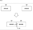
- FIG. 1 is a block diagram illustrating a configuration example of an embodiment of a communication system to which the present technology is applied.
- the communication system includes communication devices 100 and 200.
- the communication apparatuses 100 and 200 are communication apparatuses for millimeter wave communication that transmit and receive data by modulating the data into, for example, a millimeter wave band signal (millimeter wave). Data is exchanged by transmitting and receiving high-frequency signals.
- a millimeter wave is a signal having a frequency of about 30 to 300 GHz, that is, a wavelength of about 1 to 10 mm.
- the millimeter-wave signal has a high frequency, so data transmission at a high data rate (high rate) is possible.
- a millimeter-wave carrier of about 60 GHz has a rate of about 11 Gbps.
- communication can be performed using various types of transmission paths. That is, according to the millimeter waveband signal, for example, communication (wireless communication) using a space such as free space as a transmission path can be performed using a small antenna.
- communication using a metallic line as a transmission path and communication using a dielectric such as plastic as a transmission path can be performed.
- millimeter wave band modulation signals are transmitted and received between the communication device 100 and the communication device 200 in compliance with the law regulating radio waves without a radio license.
- a millimeter-wave band modulation signal is transmitted and received between the communication device 100 and the communication device 200.
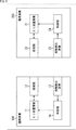
- FIG. 2 is a block diagram illustrating a first configuration example of the communication apparatuses 100 and 200 of FIG.
- the communication device 100 includes a millimeter wave communication device 11, a waveguide 12, a contact detection device 13, and a control unit 14.
- the millimeter wave communication device 11 frequency-converts (modulates) the baseband signal, which is data to be transmitted, into a millimeter wave band modulation signal, and transmits the modulation signal to the waveguide 12.
- the millimeter wave communication device 11 receives a modulation signal in the millimeter wave band transmitted from the communication device 200 via the waveguide 12, that is, a modulation signal propagating through the waveguide 12, and converts it into a baseband signal. Output after frequency conversion (demodulation).
- the waveguide 12 is made of a dielectric material such as plastic.
- the waveguide 12 has, for example, an elongated plate shape, one end face in the longitudinal direction is connected to the millimeter wave communication device 11, and the other end face is outside the communication device 100 (for example, the surface of the housing). ) Is exposed.
- the contact detection device 13 detects whether the communication device 100 is in contact with the communication device 200 (such as another communication device capable of millimeter wave communication).
- the contact detection device 13 performs contact detection as to whether or not a waveguide 12 of the communication device 100 and a waveguide 22 (to be described later) of the communication device 200 are in contact with each other, and a detection result of the contact detection. Is supplied to the control unit 14.
- the control unit 14 controls the millimeter wave communication device 11 according to the detection result of the contact detection from the contact detection device 13.
- the control unit 14 controls the millimeter wave communication device 11, and from the millimeter wave communication device 11, Millimeter wave signal (modulated signal or carrier) is transmitted.
- the control unit 14 controls the millimeter wave communication device 11 and the millimeter wave communication device 11. Limit (prohibit) the transmission of millimeter-wave band signals from.
- the communication device 200 includes a millimeter wave communication device 21, a waveguide 22, a contact detection device 23, and a control unit 24. Since the millimeter wave communication device 21 to the control unit 24 are configured in the same manner as the millimeter wave communication device 11 to the control unit 14, respectively, description thereof is omitted.
- a method of contact detection in the contact detection devices 13 and 23 for example, a method using pressure-sensitive conductive rubber, a method of detecting a change in capacitance, a method of detecting deformation by light blocking, an optical tactile image
- a method of detecting for example, a method using pressure-sensitive conductive rubber, a method of detecting a change in capacitance, a method of detecting deformation by light blocking, an optical tactile image
- a method of detecting a method of detecting conduction or non-conduction, a method using an acoustic resonance tactile element, a method of detecting a change in contact resistance, and the like.
- the control unit 14 is necessary. Accordingly, the millimeter wave communication device 11 transmits a millimeter wave band modulation signal.
- the millimeter-wave communication device 11 converts a baseband signal from a circuit (not shown) into a millimeter-wave band modulation signal and transmits it.
- the modulated signal transmitted by the millimeter wave communication device 11 propagates through the waveguide 12, further propagates through the waveguide 22 of the communication device 200 in contact with the waveguide 12, and is received by the millimeter wave communication device 21. .
- the millimeter wave communication device 21 converts the frequency of the modulation signal received via the waveguide 22 (the modulation signal propagated through the waveguide 22) into a baseband signal and supplies the baseband signal to a circuit (not shown).
- the control unit 24 detects the millimeter wave communication device 21 as necessary. Then, a millimeter-wave band modulation signal is transmitted.
- the millimeter wave communication device 21 frequency-converts a baseband signal from a circuit (not shown) into a modulation signal in the millimeter wave band and transmits it.
- the modulated signal transmitted by the millimeter wave communication device 21 propagates through the waveguide 22, further propagates through the waveguide 12 of the communication device 100 in contact with the waveguide 22, and is received by the millimeter wave communication device 11. .
- the millimeter wave communication device 11 converts the modulation signal received via the waveguide 22 into a baseband signal and supplies it to a circuit (not shown).
- the control unit 14 receives the millimeter wave from the millimeter wave communication device 11. Limit transmission of waveband signals.
- the control unit 24 receives the signal from the millimeter wave communication device 21. Limit transmission of millimeter-wave signals.
- the contact detection devices 13 and 23 are used for detecting contact between the communication device 100 (the waveguide 12) and the communication device 200 (the waveguide 22). Therefore, the communication devices 100 and 200 may be increased in size and cost.
- FIG. 3 is a block diagram illustrating a second configuration example of the communication apparatuses 100 and 200 of FIG.
- the communication device 100 includes a millimeter wave communication device 111, a waveguide 112, and a control unit 113.
- the millimeter wave communication device 111 frequency-converts (modulates) the baseband signal, which is data to be transmitted, into a millimeter wave band modulation signal, and transmits the modulation signal to the waveguide 112.
- the millimeter wave communication device 111 receives a modulation signal in the millimeter wave band transmitted through the waveguide 112, that is, a modulation signal propagated through the waveguide 112, and converts the frequency into a baseband signal (demodulation). ) And output.
- the waveguide 112 is configured, for example, by filling a hollow metal with a dielectric such as plastic.
- the waveguide 112 has, for example, an elongated plate shape, one end face in the longitudinal direction is connected to the millimeter wave communication device 111, and the other end face is outside the communication device 100 (for example, the surface of the housing). ) Is exposed.
- a millimeter wave band signal transmitted by the millimeter wave transmitter 111 propagates through the waveguide 112. Further, a millimeter wave band signal received by the millimeter wave transmitter 111 is propagated through the waveguide 112.
- the control unit 113 controls the millimeter wave communication device 111 according to a millimeter wave band signal received by the millimeter wave communication device 111 via the waveguide 112.
- the millimeter wave communication device 111 has a detection mode and a communication mode as operation modes.
- the detection mode contact between the waveguide 112 of the communication device 100 and the waveguide 212 of the communication device 200 is detected.
- a millimeter-wave band modulation signal obtained by frequency conversion of the baseband signal is transmitted / received (transmitted / received) through the waveguides 112 and 212 between the communication device 100 and the communication device 200.
- the control unit 113 sets the operation mode to the detection mode or the communication mode according to the millimeter wave band signal received by the millimeter wave communication device 111 via the waveguide 112.
- the communication device 200 includes a millimeter wave communication device 211, a waveguide 212, and a control unit 213. Since the millimeter wave communication device 211 to the control unit 213 are configured in the same manner as the millimeter wave communication device 111 to the control unit 113, description thereof will be omitted.
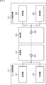
- FIG. 4 is a diagram illustrating a configuration example of the millimeter wave communication devices 111 and 211 and the waveguides 112 and 212 of FIG.
- the millimeter wave communication device 111 includes a transmitter 121 and a receiver 122.
- the transmitter 121 converts the frequency of the baseband signal into a modulated signal in the millimeter wave band and transmits it from the antenna 123 to the waveguide 112.
- the receiver 122 propagates through the waveguide 112, receives a millimeter-wave band modulation signal supplied via the antenna 123, and converts the frequency into a baseband signal.
- an antenna 123 is an antenna that is used for both transmission and reception, and is connected to a dielectric constituting the waveguide 112.
- the waveguide 112 is composed of one waveguide that is used for both transmission and reception.
- the waveguide 112 is also a waveguide (first waveguide) on the transmitter 121 side where a signal transmitted by the transmitter 121 is propagated, and a signal received by the receiver 122 is propagated. It is also the waveguide on the receiver 122 side.
- the millimeter wave communication device 211 includes a transmitter 221 and a receiver 222.
- the transmitter 221 and the receiver 222 are configured in the same manner as the transmitter 121 and the receiver 122, respectively.
- the transmitter 221 transmits a millimeter-wave band modulation signal from the antenna 223 to the waveguide 212 in the same manner as the transmitter 121.
- the receiver 222 propagates through the waveguide 212 and receives a millimeter wave band modulation signal supplied via the antenna 223.
- the antenna 223 is an antenna that is used for both transmission and reception, and is connected to a dielectric constituting the waveguide 212 in the same manner as the antenna 123.
- the waveguide 212 in response to the antenna 223 being an antenna that is used for both transmission and reception, is constituted by one waveguide that is used for both transmission and reception.
- the waveguide 212 is also a waveguide on the transmitter 221 side where the signal transmitted by the transmitter 221 propagates, and the signal received by the receiver 222 is propagated (coming) on the receiver 222 side. It is also a waveguide (second waveguide).
- the millimeter wave communication device 111 includes the transmitter 121 and the receiver 122 and the millimeter wave communication device 211 includes the transmitter 221 and the receiver 222, the millimeter wave communication device 111. And 211 can be bidirectionally communicated.
- the millimeter-wave communication device 111 transmits the modulation signal in the millimeter wave band transmitted by the transmitter 121 to the antenna 123. Then, it propagates through the waveguides 112 and 212 and is received by the receiver 222 via the antenna 223. Also, in the millimeter wave communication device 211, the millimeter wave band modulation signal transmitted from the transmitter 221 propagates from the antenna 223 through the waveguides 212 and 112 and is received by the receiver 122 via the antenna 123.
- the transmitters 121 and 221 use millimeter wave signals in the same frequency band as carriers.
- half-duplex communication can be performed between the millimeter wave communication devices 111 and 211.
- full-duplex communication can be performed between the millimeter wave communication devices 111 and 211.
- the millimeter wave communication device 111 when performing communication in one direction in the communication system, that is, for example, when transmitting data from the millimeter wave communication device 111 to only one direction of the millimeter wave communication device 211, the millimeter wave communication device 111 is a receiver.
- the millimeter wave communication device 211 can be configured without the transmitter 221.
- FIG. 5 is a diagram illustrating another configuration example of the millimeter wave communication devices 111 and 211 and the waveguides 112 and 212 in FIG.
- the communication system includes transmission antennas 123S and 223S, reception antennas 123R and 223R, transmission waveguides 112S and 212S, and reception waveguides 112R and 212R. This is different from the case of FIG. 4 having antennas 123 and 223 that are used for both transmission and reception, and waveguides 112 and 212.
- the waveguide 112 has a transmission waveguide 112S and a reception waveguide 112R.
- the waveguide 212 includes a transmission waveguide 212S and a reception waveguide 212R.
- the waveguides 112S, 112R, 212S, and 212R are each configured, for example, by filling a hollow metal with a predetermined dielectric.
- the waveguides 112 and 212 are such that when the millimeter wave communication devices 111 and 112 are brought into contact, the waveguides 112S and 212R are in contact with each other, and the waveguides 112R and 212S are in contact with each other. It is configured.
- the antenna 123S is an antenna for transmission, and is connected to a dielectric constituting the waveguide 112S for transmission.
- the millimeter-wave band modulation signal transmitted from the transmitter 121 propagates from the antenna 123S to the waveguide 112S.
- the antenna 123R is a receiving antenna and is connected to a dielectric constituting the receiving waveguide 112R.
- the millimeter-wave band modulation signal propagating through the waveguide 112R is received by the receiver 122 via the antenna 123R.
- the antenna 223S is a transmission antenna and is connected to a dielectric constituting the transmission waveguide 212S.
- the millimeter wave band modulation signal transmitted by the transmitter 221 propagates from the antenna 223S to the waveguide 212S.
- the antenna 223R is a receiving antenna and is connected to a dielectric constituting the receiving waveguide 212R.
- the millimeter-wave band modulation signal propagating through the waveguide 212R is received by the receiver 222 via the antenna 223R.
- the waveguide 112 ⁇ / b> S is a waveguide on the transmitter 121 side (the first waveguide) through which the signal transmitted by the transmitter 121 propagates, and the waveguide 212 ⁇ / b> R is received by the receiver 222.
- This is a waveguide (second waveguide) on the receiver 222 side through which a signal propagates.
- the waveguide 212S is a waveguide on the transmitter 221 side through which a signal transmitted by the transmitter 221 propagates.
- the waveguide 112R is a receiver 122 through which a signal received by the receiver 122 propagates. Side waveguide.
- the communication system includes transmission antennas 123S and 223S, reception antennas 123R and 223R, transmission waveguides 112S and 212S, and reception waveguides 112R and 212R.
- the modulation signal in the millimeter wave band transmitted by the transmitter 121 is The antenna 123S propagates through the waveguides 112S and 212R, and is received by the receiver 222 via the antenna 223R. Also, the millimeter-wave band modulation signal transmitted by the transmitter 221 propagates from the antenna 223S through the waveguides 212S and 112R, and is received by the receiver 122 via the antenna 123R.
- the present technology may be applied to the case where each of the waveguide 112 and the waveguide 212 is configured by one waveguide that is used for both transmission and reception.
- the waveguide 112 includes a transmission waveguide 112S and a reception waveguide 112R
- the waveguide 212 includes a transmission waveguide 212S and a reception waveguide.
- the present invention can also be applied to the case of having the waveguide 212R.
- each of the waveguide 112 and the waveguide 212 is configured by one waveguide that is used for both transmission and reception. I will do it.
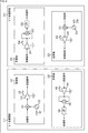
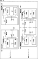
- FIG. 6 is a diagram illustrating a configuration example of the transmitter 121 and the receiver 122 of the millimeter wave communication device 111 and the transmitter 221 and the receiver 222 of the millimeter wave communication device 211.
- the transmitter 121 includes a mixer 131, an oscillator 132, an amplifier 133, and switches 134 and 135.
- the mixer 131 is supplied with a baseband signal (BB signal) from a circuit (not shown) and with a millimeter-wave band carrier from the oscillator 132.
- BB signal baseband signal
- a circuit not shown
- a millimeter-wave band carrier from the oscillator 132.
- the mixer 131 mixes (multiplies) the baseband signal and the carrier from the oscillator 132 to frequency-convert the baseband signal by the carrier from the oscillator 132 (modulates the carrier according to the baseband signal).
- a modulation signal of millimeter wave band for example, amplitude modulation (ASK (Amplitude Shift Keying)
- ASK Amplitude Shift Keying
- the mixer 133 supplies the carrier from the oscillator 132 to the amplifier 133 as it is.
- the oscillator 132 generates a millimeter wave band carrier of, for example, 56 GHz by oscillation and supplies the carrier to the mixer 131.
- the amplifier 133 amplifies the signal (modulated signal or carrier) from the mixer 131 with a predetermined gain as necessary, and outputs the amplified signal.
- the signal output from the amplifier 133 is transmitted to the waveguide 112 (from the antenna 123 (FIG. 4)).
- the gain of the amplifier 133 (the degree of amplification of the signal from the mixer 133) can be set according to the control of the control unit 113 (FIG. 3).
- the switches 134 and 135 are turned on or off according to the control of the control unit 113 (FIG. 3).
- the oscillator 132 is turned on or off.
- the amplifier 133 is turned on or off.
- the receiver 222 includes an amplifier 241, a mixer 242, an LPF (Low Pass Filter) 243, and a switch 244.
- LPF Low Pass Filter
- the amplifier 241 receives a millimeter-wave band signal (modulated signal or carrier) propagating through the waveguide 212, amplifies the signal with a predetermined gain as necessary, and supplies the amplified signal to the mixer 242.
- a millimeter-wave band signal modulated signal or carrier
- the band (reception band) of the millimeter-wave band signal amplified by the amplifier 241 can be set according to the control of the control unit 213 (FIG. 3).
- the mixer 242 performs square detection to mix the modulation signals in the millimeter wave band supplied from the amplifier 241 (square the modulation signal), thereby converting the modulation signal in the millimeter wave band from the amplifier 241 into a baseband signal.
- the frequency is converted (the demodulated signal is demodulated into a baseband signal) and supplied to the LPF 243.
- the LPF 243 performs filtering that passes the low frequency range of the signal from the mixer 243, and outputs a baseband signal obtained by the filtering.
- the pass band of the LPF 243 can be set according to the control of the control unit 213.
- the switch 244 is turned on or off according to the control of the control unit 213.
- the amplifier 241 is turned on or off.
- the receiver 222 frequency-converts the modulation signal in the millimeter wave band into a baseband signal by square detection, but the receiver 222 reproduces a carrier, for example,
- the modulation signal can be converted into a baseband signal by detection other than square detection, such as synchronous detection for mixing the carrier with the modulation signal.
- the transmitter 221 includes a mixer 231, an oscillator 232, an amplifier 233, and switches 234 and 235.
- mixer 231 to the switch 235 are configured in the same manner as the mixer 131 to the switch 135 of the transmitter 121, description thereof will be omitted.
- the receiver 122 includes an amplifier 141, a mixer 142, an LPF 143, and a switch 144.
- FIG. 7 is a diagram for explaining the operation mode of the millimeter wave communication devices 111 and 211 in FIG.
- the millimeter wave communication devices 111 and 211 have a detection mode and a communication mode as operation modes.
- the operation modes of the millimeter wave communication devices 111 and 211 are changed from the detection mode to the communication mode. It becomes.
- a millimeter-wave band modulation signal is transmitted and received between the communication device 100 and the communication device 200 via the waveguides 112 and 212.
- FIG. 8 is a diagram for explaining the detection mode.
- one communication device requests the start of communication, and the other communication device Communication is started in response to a request from the communication device.
- a communication device millimeter wave communication device that requests the start of communication
- a communication device that starts communication in response to a request from the initiator is also referred to as a target.
- the communication devices 100 and 200 (the millimeter wave communication devices 111 and 211), for example, the communication device 100 (the millimeter wave communication device 111) is used as an initiator, and the communication device 200 (the millimeter wave communication device). 211 will be described as a target.
- the transmitter 121 of the communication apparatus 100 as an initiator transmits a predetermined signal (from the antenna 123) to the waveguide 112.
- the predetermined signal transmitted by the transmitter 121 in the detection mode is, for example, a narrowband signal that is narrower than a millimeter-wave band modulation signal transmitted in the communication mode and is a low-level signal.
- a level signal can be employed.
- the narrow band low level signal is a millimeter wave band carrier signal output from the oscillator 132 (FIG. 6), and the gain of the amplifier 133 (FIG. 6) is transmitted in the communication mode. It is possible to employ a signal with a low level (hereinafter also referred to as a low level carrier) obtained by setting the gain lower than that when amplifying the signal.
- a low level carrier a signal with a low level (hereinafter also referred to as a low level carrier) obtained by setting the gain lower than that when amplifying the signal.
- the narrowband low level signal is a modulated signal obtained by modulating a millimeter wave band carrier with a baseband signal having a lower rate (narrowband) than the baseband signal transmitted in the communication mode.
- a low-level signal (hereinafter also referred to as a low-rate modulation signal) obtained by setting the gain to a lower gain than when a millimeter-wave band modulation signal transmitted in the communication mode is amplified can be employed.
- the narrow-band low-level signal transmitted from the transmitter 121 to the waveguide 112 propagates through the waveguide 112 and reaches the outer end face of the waveguide 112.
- the end face on the outer side of the waveguide 112 is in contact with a space (in the atmosphere or the like).
- the light is reflected by the end face on the outside of 112. Therefore, there is almost no radio wave leakage of the narrow-band low-level signal from the outer end face of the waveguide 112.
- the degree (intensity) of the radio wave leakage is slight, and the narrow band low level signal is a narrow band, low level signal. Radio waves of high-level signals and broadband signals that violate are not radiated.
- the narrow-band low-level signal does not reach the communication device 200 from the communication device 100 or does not reach the communication device 200.
- the narrowband low level signal that is propagated and received by the receiver 222 is a very low level signal.
- FIG. 8A shows an example of the level of a narrowband low-level signal received by the receiver 222 of the communication device 200 when the communication device 100 and the communication device 200 are separated in the detection mode.
- the receiver 222 has received a narrow-band low-level signal having a level less than a predetermined threshold value for the detection mode.
- the transmitter 121 has transmitted.
- the narrow band low level signal propagates through the waveguides 112 and 212 in contact with each other and reaches the receiver 222 to be received with a certain level maintained.
- the level of the narrowband low-level signal received by the receiver 222 via the waveguide 212 is the case where the waveguides 112 and 212 are not in contact ( When the communication device 100 and the communication device 200 are separated from each other), the signal level greatly increases from the level of the narrowband low-level signal received by the receiver 222 via the waveguide 212.
- FIG. 8B shows an example of the level of a narrowband low-level signal received by the receiver 222 of the communication device 200 when the waveguide 112 of the communication device 100 and the waveguide 212 of the communication device 200 are in contact with each other. Is shown.
- the receiver 222 receives a narrowband low-level signal having a level equal to or higher than the threshold value for the detection mode.
- control units 113 and 213 change the operation mode according to the narrowband low level signal received through the waveguide 212 by the receiver 222 of the communication device 200 that is the target. Set.
- the control units 113 and 213 control the waveguides 112 and 212.
- the operation mode is set from the detection mode to the communication mode.
- the operation mode of the transmitter 121 (including the communication device 100) and the operation mode of the receiver 222 (including the communication device 200) are changed from the detection mode to the communication mode.
- a predetermined high-rate baseband signal is frequency-converted by a carrier into a millimeter-wave band modulation signal. Further, in the transmitter 121, the modulated signal is amplified by the amplifier 133 with a predetermined high gain, and a modulated signal having a level and frequency band larger than that of the narrow band low level signal is transmitted.
- the modulated signal transmitted by the transmitter 121 propagates through the waveguides 112 and 212 that are in contact with each other, and reaches the receiver 222 and is received while maintaining a certain level.
- the modulated signal transmitted from the transmitter 121 and propagated through the waveguides 112 and 212 is a signal whose level and frequency band are larger than those of the narrow band low level signal. Since there is no contact, there is no leakage of modulated signals as radio waves.
- the level of the narrowband low-level signal transmitted by the transmitter 121 in the detection mode and the threshold value for the detection mode are regulated by radio wave leakage when the communication device 100 and the communication device 200 are separated from each other. While complying with the law, the level of the narrowband low level signal received by the receiver 222 when the communication device 100 and the communication device 200 are separated is less than the threshold for the detection mode, and the waveguides 112 and 212 Is adjusted in advance so that the level of the narrow-band low-level signal received by the receiver 222 is equal to or higher than the threshold value for the detection mode.
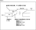
- FIG. 9 is a diagram for explaining a first simulation for investigating the relationship between the gaps between the waveguides and the transmission characteristics between the waveguides.
- elongated waveguides having a rectangular cross section were used as the waveguides 112 and 212.
- the four surfaces of the waveguides 112 and 212 perpendicular to the cross section are surrounded by metal, and the inside is filled with a dielectric.
- the width x length of the cross section of the waveguides 112 and 212 is 3 mm x 1 mm, and the thickness of the four metal surfaces orthogonal to the cross section is 0.1 mm.
- dielectric PA a dielectric having a dielectric constant of 2.1 and a dielectric loss tangent of 0.001 (Teflon (registered trademark)) is used.
- dielectric PB a dielectric having a dielectric constant of 10.2 and a dielectric loss tangent of 0.001 is used. It was.
- the end faces of the waveguides 112 and 212 are arranged so as to face each other, the gap between the end faces is set to various distances, and the transmission coefficient S21 of the S parameter from the waveguides 112 to 212 is set.
- the transmission coefficient S21 of the S parameter from the waveguides 112 to 212 was set.
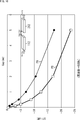
- FIG. 10 is a diagram showing a simulation result of the first simulation described in FIG.
- FIG. 10 shows the relationship between the gap between the waveguides 112 and 212 and the transfer coefficient S21 from the waveguides 112 to 212 obtained in the first simulation.
- the transfer coefficient S21 decreases more rapidly when the dielectric PB is used than when the dielectric PA is used.
- the degree of change (decrease) in the transmission coefficient S21 when the gap distance between the end faces of the waveguides 112 and 212 changes from 0 to a non-zero state depends on the dielectric (dielectric constant) filling the waveguides 112 and 212. ) And the shape of the cross section of the waveguides 112 and 212 can be adjusted.
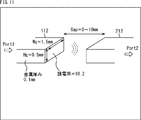
- FIG. 11 is a diagram for explaining a second simulation for investigating the relationship between the gaps between the waveguides and the transmission characteristics between the waveguides.
- the waveguides 112 and 212 are long and thin plate-like waveguides having a rectangular cross section, and four surfaces perpendicular to the cross section are surrounded by metal, and the inside is a dielectric.
- a waveguide filled with body was used.
- the width ⁇ length (Wg ⁇ Hg) of the cross sections of the waveguides 112 and 212 is 1.5 mm ⁇ 0.5 mm, and the thickness of the four metal surfaces orthogonal to the cross section is 0.1 mm. .
- the dielectric PB described with reference to FIG. 9 is used as the dielectric filling the waveguides 112 and 212.
- the dielectric PB is a dielectric having a dielectric constant of 10.2 and a dielectric loss tangent of 0.001.
- the end faces of the waveguides 112 and 212 are arranged to face each other, and the gap between the end faces is set to various distances, so that the waveguides 112 to 212 are moved.
- the S parameter transmission coefficient S21 was measured.
- FIG. 12 is a diagram showing a simulation result of the second simulation explained in FIG.
- FIG. 12 shows the relationship between the carrier frequency and the transfer coefficient S21 from the waveguides 112 to 212, for each of the plurality of gaps between the waveguides 112 and 212, obtained in the second simulation. Show.
- the gap distance between the end faces of the waveguides 112 and 212 changes from 0 to a non-zero state, that is, the waveguide 112. It can be confirmed that the transmission coefficient S21 decreases rapidly when the distance between the contact point 212 and the contact point 212 slightly differs.
- FIG. 13 is a diagram for explaining the detection mode and the communication mode.
- FIG. 13A is a diagram for explaining the detection mode.
- the transmitter 121 of the communication device 100 as the initiator transmits a narrowband low-level signal to the waveguide 112.
- the narrow band low level signal may be, for example, a level obtained by modulating a carrier with a low level carrier (a carrier with a low level) or a low rate modulation signal (a low rate (narrow band) baseband signal).
- a low modulation signal may be, for example, a level obtained by modulating a carrier with a low level carrier (a carrier with a low level) or a low rate modulation signal (a low rate (narrow band) baseband signal).
- a low modulation signal may be, for example, a level obtained by modulating a carrier with a low level carrier (a carrier with a low level) or a low rate modulation signal (a low rate (narrow band) baseband signal).
- the narrow-band low-level signal transmitted from the transmitter 121 to the waveguide 112 propagates through the waveguide 112 and reaches the outer end face of the waveguide 112.
- the level of the radio wave leak is slight, and furthermore, the narrow band low level signal is a narrow band, low level signal. Radio waves of high level signals and broadband signals are not radiated.
- the narrowband low-level signal does not reach the communication device 200 from the communication device 100 or does not reach the communication device 200.
- a narrow-band low-level signal that propagates through the waveguide 212 and is received by the receiver 222 is a signal with a very low level.
- the level of the narrowband low-level signal received by the receiver 222 is lower than a predetermined threshold value for the detection mode.
- the communication devices 100 and 200 When the level of the narrowband low-level signal received by the target communication device 200 (the receiver 222) is a level lower than the threshold for the detection mode, the communication devices 100 and 200 (respective transmitter 121 and reception). The detection mode is maintained as the operation mode of the machine 222).
- the reception sensitivity can be improved by reducing the thermal noise by narrowing the reception band in the detection mode.
- the receiver 222 can narrow the reception band by, for example, narrowing the band of the signal to be amplified by the amplifier 241 in FIG. 6 or narrowing the passband of the LPF 243.
- the narrow-band low-level signal transmitted by the transmitter 121 propagates through the contacted waveguides 112 and 212.
- the signal reaches the receiver 222 and is received while maintaining a certain level.
- the level of the narrowband low level signal received by the receiver 222 via the waveguide 212 is the same as when the waveguides 112 and 212 are not in contact.
- the receiver 222 greatly increases from the level of the narrow-band low-level signal received via the waveguide 212, and becomes a level equal to or higher than the threshold for the detection mode.
- the operation mode of the communication devices 100 and 200 (respective transmitter 121 and receiver 222) is set to the detection mode. To the communication mode.
- FIG. 13B is a diagram illustrating the communication mode.
- a predetermined high-rate baseband signal is frequency-converted into a millimeter-wave band modulation signal by a carrier. Furthermore, in the transmitter 121, the modulated signal is amplified with a predetermined high gain by the amplifier 133 (FIG. 6), and a modulated signal having a level and frequency band larger than that of the narrow band low level signal is transmitted.
- the modulated signal transmitted by the transmitter 121 propagates through the waveguides 112 and 212 that are in contact with each other, and reaches the receiver 222 and is received while maintaining a certain level.
- the modulated signal transmitted from the transmitter 121 and propagated through the waveguides 112 and 212 is a signal whose level and frequency band are larger than those of the narrow band low level signal. Since there is no contact, there is no leakage of modulated signals as radio waves.
- the operation mode is changed from the detection mode to the communication mode. Then, by expanding (returning to) the reception band, a modulated signal having a large frequency band, that is, a high-rate baseband signal is received.
- FIG. 14 is a flowchart for explaining an example of the operation of the communication device 100 as an initiator and the communication device 200 as a target.
- step S11 the control unit 113 (FIG. 3) sets the operation mode to the detection mode, and the process proceeds to step S12.
- step S12 in response to the fact that the operation mode is the detection mode, the transmitter 121 of the communication device 100 transmits a narrowband low level signal, and the process proceeds to step S13.
- step S13 the control unit 113 of the communication device 100 determines whether or not a signal having a level equal to or higher than the threshold value is received by the receiver 122 (FIG. 6).
- the target communication device 200 when a narrowband low level signal having a level equal to or higher than the detection mode threshold is received by the receiver 222, the target communication device 200 indicates that the narrowband low level signal has been received.
- the transmitter 221 transmits a reception confirmation signal (for example, a narrow band (low rate) modulated signal obtained by modulating the carrier with a carrier itself or a baseband signal indicating reception of a narrow band low level signal).
- a reception confirmation signal for example, a narrow band (low rate) modulated signal obtained by modulating the carrier with a carrier itself or a baseband signal indicating reception of a narrow band low level signal.
- the reception confirmation signal transmitted by the communication device 200 propagates through the waveguide 212 (receive Most of the confirmation signals are reflected on the end face exposed on the surface of the casing of the communication device 100.
- the reception confirmation signal transmitted by the communication device 200 does not reach or reaches the receiver 122 of the communication device 100, the reception confirmation signal received by the receiver 122 of the communication device 100 has an extremely low level. Signal.
- the reception confirmation signal transmitted by the communication device 200 is transmitted through the waveguides 212 and 112. Propagated and received at a certain level at the receiver 122 of the communication device 100.
- the receiver 122 receives a reception confirmation signal having a level equal to or higher than the threshold value.
- step S13 the control unit 113 of the communication device 100 receives, in the receiver 122, whether or not the reception belief signal from the communication device 200 is received at a threshold level or higher, that is, a reception confirmation signal at a level higher than the threshold is received. Determine whether or not.
- step S13 If it is determined in step S13 that a reception confirmation signal having a level equal to or higher than the threshold has not been received, that is, the waveguide 112 of the communication device 100 and the waveguide 212 of the communication device 200 are not in contact with each other.
- the reception confirmation signal of the level more than a threshold value cannot be received from the communication apparatus 200, a process returns to step S12 and the same process is repeated hereafter.
- step S13 if it is determined in step S13 that a reception confirmation signal having a level equal to or higher than the threshold value has been received, that is, the waveguide 112 of the communication device 100 and the waveguide 212 of the communication device 200 are in contact with each other.
- the reception confirmation signal having a level equal to or higher than the threshold value is received from the communication apparatus 200, the process proceeds to step S14.
- step S14 the control unit 113 of the communication device 100 uses a mode switching signal that requests the operation mode to be switched from the detection mode to the communication mode (for example, a carrier itself or a baseband signal that requests switching to the communication mode).
- the narrowband modulated signal obtained by modulating the carrier is transmitted to the transmitter 121, and the process proceeds to step S15.
- the mode switching signal transmitted by the transmitter 121 of the communication device 100 propagates through the waveguides 112 and 212 that are in contact with each other, and is received by the receiver 222 of the communication device 200.
- the communication apparatus 200 When the communication apparatus 200 receives the mode switching signal by the receiver 222, the communication apparatus 200 transmits a switching confirmation signal indicating that the mode switching signal has been received from the transmitter 221 as described later.
- the switching confirmation signal transmitted by the transmitter 221 propagates through the waveguides 212 and 112 that are in contact with each other, and is received by the receiver 122 of the communication device 100.
- step S15 the communication apparatus 100 enters a standby state in which it waits for a switching confirmation signal transmitted from the transmitter 221 of the communication apparatus 200, and the process proceeds to step S16.
- step S ⁇ b> 16 the control unit 113 of the communication device 100 receives, in the receiver 122, whether or not the switching belief signal from the communication device 200 has been received at a threshold level or higher, that is, a switching confirmation signal at a level higher than the threshold. Determine whether or not.
- step S16 If it is determined in step S16 that the receiver 122 has not received a switching confirmation signal having a level equal to or higher than the threshold value, the process returns to step S12, and the same process is repeated thereafter.
- step S16 when the waveguide 122 and the waveguide 212 are brought into contact with each other and the contact is released, the receiver 122 cannot receive a switching confirmation signal having a level equal to or higher than the threshold value. Returns from step S16 to step S12, and the transmission of the narrowband low-level signal is repeated.
- step S16 if it is determined in step S16 that the receiver 122 has received a switching confirmation signal having a level equal to or higher than the threshold value, the process proceeds to step S17.
- the communication device 100 has a level equal to or higher than the threshold from the communication device 200.
- step S ⁇ b> 17 the control unit 113 of the communication apparatus 100 detects the reception confirmation signal and the switching confirmation signal at a level equal to or higher than the threshold value from the communication apparatus 200, that is, detected by the receiver 222 of the communication apparatus 200.
- the operation mode of the communication apparatus 100 is set (switched) from the detection mode to the communication mode, and the process proceeds to step S18.
- step S18 the control unit 113 of the communication apparatus 100 controls the transmitter 121 and the receiver 122 to obtain a signal obtained by amplifying a modulated signal obtained by modulating a carrier with a high-rate baseband signal with a high gain.
- Transmission / reception of the contacted waveguides 112 and 212 (hereinafter also referred to as a broadband high level signal) is started, and the process proceeds to step S19.
- step S19 the control unit 113 of the communication apparatus 100 determines whether or not the receiver 122 (FIG. 6) can no longer receive a signal having a level equal to or higher than the threshold value.
- the communication devices 100 and 200 change from the detection mode to the communication mode and start transmission / reception of a broadband high-level signal.
- a broadband high level signal transmitted by transmitter 221 of communication device 200 is equal to or greater than a predetermined broadband high level signal threshold (hereinafter also referred to as a communication mode threshold). Can be received at any level.
- the receiver 222 of the communication device 200 can receive the broadband high-level signal transmitted by the transmitter 121 of the communication device 100 at a level equal to or higher than the threshold for the communication mode.
- the level of the broadband high-level signal from the communication device 200 that propagates through the waveguide 112 and is received by the receiver 122 of the communication device 100 is ,descend.
- the level of the broadband high-level signal from the communication device 100 that propagates through the waveguide 212 and is received by the receiver 222 of the communication device 200 also decreases.
- the broadband at a level equal to or higher than the threshold for the communication mode in both the receiver 112 of the communication device 100 and the receiver 212 of the communication device 200.
- the high level signal cannot be received.
- step S19 as described above, the control unit 113 of the communication device 100 releases the contact between the waveguide 112 and the waveguide 212, and the receiver 112 of the communication device 100 has a wide band at a level equal to or higher than the threshold for the communication mode. It is determined whether a high level signal can no longer be received.
- step S19 If it is determined in step S19 that the receiver 112 of the communication apparatus 100 has received a broadband high level signal having a level equal to or higher than the threshold for the communication mode, the process returns to step S19, and the same process is performed thereafter. Repeated.
- the contact between the waveguide 112 and the waveguide 212 is maintained, and the receiver 112 of the communication device 100 receives a broadband high-level signal having a level equal to or higher than the threshold for the communication mode from the communication device 200. If it is possible, the communication mode is maintained and transmission / reception of the broadband high level signal is continued.
- step S19 if it is determined in step S19 that the receiver 112 of the communication apparatus 100 can no longer receive a broadband high level signal having a level equal to or higher than the threshold for the communication mode, the process returns to step S11.
- step S11 as described above, the control unit 113 of the communication device 100 sets the operation mode to the detection mode, and thereafter, the same processing is repeated.
- the operation mode is switched from the communication mode to the detection mode.
- step S31 the control unit 213 (FIG. 3) sets the operation mode to the detection mode, and the process proceeds to step S32.
- step S32 the receiver 222 of the communication apparatus 200 starts receiving the narrowband low level signal, and the process proceeds to step S33.
- the communication device 100 that is an initiator transmits a narrowband low-level signal in step S12, so that the receiver 222 of the communication device 200 that is a target communicates in step S32.
- the reception of the narrow band low level signal from the apparatus 100 is started.
- step S33 the control unit 213 of the communication device 200 determines whether or not the receiver 222 (FIG. 6) has received a narrowband low-level signal having a level equal to or higher than the detection mode threshold.
- step S33 If it is determined in step S33 that the receiver 222 has not received a narrowband low level signal having a level equal to or higher than the threshold value for the detection mode, the process returns to step S33, and the same process is repeated thereafter.
- the level of the narrowband low-level signal from the communication device 100 received by the receiver 222 of the communication device 200 is less than the threshold for the detection mode. , Reception of the narrowband low level signal at the receiver 222 is continued.
- step S33 if it is determined in step S33 that the receiver 222 has received a narrowband low-level signal having a level equal to or higher than the detection mode threshold, the process proceeds to step S34.
- the waveguide 112 and the waveguide 212 are in contact with each other, and therefore the level of the narrow-band low-level signal received from the communication device 100 and received by the receiver 222 of the communication device 200 is equal to or higher than the detection mode threshold. If so, the process proceeds to step S34.
- step S34 the control unit 213 of the communication apparatus 200 controls the transmitter 221 to transmit a reception confirmation signal in response to receiving the narrowband low level signal having a level equal to or higher than the detection mode threshold.
- the process proceeds to step S35.
- step S35 the communication apparatus 200 waits for the mode switching signal transmitted from the communication apparatus 100 in step S14, and the process proceeds to step S36.
- step S36 the control unit 213 of the control unit 200 determines whether the mode switching signal from the communication device 100 is received by the receiver 222.
- the reception confirmation signal transmitted by the transmitter 221 in step S34 propagates through the waveguides 212 and 112 that are in contact with each other, and is received at the receiver 122 of the communication device 100 at a level equal to or higher than the threshold value.
- the communication device 100 that has received the reception confirmation signal at the level equal to or higher than the threshold by the receiver 122 transmits the mode switching signal in step S14 as described above. Therefore, the communication device 200 waits for a mode switching signal from the communication device 100 in step S35, and determines whether a mode switching signal from the communication device 100 has been received in step S36.
- step S36 If it is determined in step S36 that the mode switching signal from the communication device 100 has not been received, the process returns to step S32, and the same process is repeated thereafter.
- step S36 the processing is performed. Then, the process returns from step S36 to step S32, and reception of a narrow band low level signal is started.
- step S36 determines in step S36 that the mode switching signal has been received.
- step S37 the control unit 213 of the communication device 200 controls the transmitter 221 in response to the reception of the mode switching signal to transmit a switching confirmation signal, and the process proceeds to step S38.
- the switching confirmation signal propagates through the contacted waveguides 212 and 112 and is received by the receiver 122 of the communication device 100.
- step S38 the control unit 213 of the communication apparatus 200 responds to the reception of the mode switching signal from the communication apparatus 100, that is, the receiver 222 has a narrow band low level that is equal to or higher than the detection mode threshold.
- the operation mode of the communication apparatus 200 is set from the detection mode to the communication mode, and the process proceeds to step S39.
- step S39 the control unit 213 of the communication apparatus 200 controls the transmitter 221 and the receiver 222 to amplify a broadband high-level signal (a modulated signal obtained by modulating a carrier with a high-rate baseband signal with a high gain). Signal) is transmitted / received via the contacting waveguides 212 and 112, and the process proceeds to step S40.
- a broadband high-level signal a modulated signal obtained by modulating a carrier with a high-rate baseband signal with a high gain.
- Signal is transmitted / received via the contacting waveguides 212 and 112, and the process proceeds to step S40.
- step S40 the control unit 213 of the communication device 2100 determines whether or not the receiver 222 cannot receive a signal having a level equal to or higher than the threshold value.
- the communication devices 100 and 200 change from the detection mode to the communication mode and start transmission / reception of a broadband high-level signal. To do.
- the transmitter 121 of the communication device 100 is connected to the receiver 222 of the communication device 200 without causing radio wave leakage of a broadband high-level signal as a radio wave.
- a broadband high-level signal to be transmitted can be received at a level equal to or higher than a threshold for the communication mode.
- the level of the broadband high-level signal received by the receiver 222 of the communication device 200 decreases.
- the receiver 212 of the communication device 200 cannot receive a broadband high-level signal having a level equal to or higher than the threshold for the communication mode.
- step S40 the control unit 213 of the communication device 200 cancels the contact between the waveguide 112 and the waveguide 212 as described above, and the receiver 212 of the communication device 200 has a broadband level equal to or higher than the threshold for the communication mode. It is determined whether a high level signal can no longer be received.
- step S40 If it is determined in step S40 that the receiver 212 of the communication apparatus 200 has received a broadband high level signal having a level equal to or higher than the threshold for the communication mode, the process returns to step S40, and the same process is performed thereafter. Repeated.
- the waveguide 112 and the waveguide 212 are in contact with each other, and the receiver 212 of the communication device 200 can receive a broadband high-level signal having a level equal to or higher than the threshold for the communication mode from the communication device 100. In this case, the communication mode is maintained, and transmission / reception of the broadband high level signal is continued.
- step S40 if it is determined in step S40 that the receiver 212 of the communication apparatus 200 is unable to receive a broadband high level signal having a level equal to or higher than the threshold for the communication mode, the process returns to step S31.
- step S31 as described above, the control unit 213 of the communication device 200 sets the operation mode to the detection mode, and thereafter, the same processing is repeated.
- the operation mode is switched from the communication mode to the detection mode.
- the transmitter 121 transmits a predetermined signal such as a narrow-band low-level signal to the waveguide 112 and is received by the receiver 222 via the waveguide 212.
- the detection mode is changed to the communication mode in response to a low-level narrow-band signal that is equal to or higher than the threshold value. Then, the transmitter 121 transmits the modulation signal via the waveguides 112 and 212 in the communication mode.
- the receiver 222 receives the narrowband low-level signal via the waveguide 212, and is received via the waveguide 212.
- the level of the narrowband low-level signal equal to or higher than the threshold for the detection mode is received. Accordingly, the communication mode is changed from the detection mode.
- the receiver 222 receives the modulated signal via the waveguides 112 and 212 in the communication mode.
- the receiver 222 when the receiver 222 receives a signal with a narrow band low level that is equal to or higher than the detection mode threshold, the contact between the waveguide 112 and the waveguide 212 is detected. If there is, the operation mode is switched from the detection mode to the communication mode, and the modulated signal is transmitted and received.
- the waveguide 112 on the transmitter 121 side and the waveguide 212 on the receiver 222 side are in the detection mode without using the contact detection devices 13 and 23 dedicated for contact detection.
- the contact can be detected, and the modulated signal can be transmitted and received while the waveguide 112 and the waveguide 212 are in contact with each other.
- the transmitter 121 and the receiver are in the detection mode and transmit and receive a narrow band low level signal. Therefore, it is possible to comply with the law that regulates radio waves.
- the transmitter 121 and the receiver 222 are in a communication mode, and a broadband high-level signal is transmitted / received. Since it is in contact with 212, it is possible to prevent radio wave leakage of a broadband high-level signal and to comply with laws regulating radio waves.
- the narrow band low level signal for example, a low level carrier or a low rate modulated signal can be adopted as described with reference to FIG.
- a low-rate modulation signal for example, a predetermined pattern that requests switching of the operation mode is adopted as the baseband signal used to generate the low-rate modulation signal Can do.
- the communication apparatus 200 can demodulate a predetermined pattern for requesting switching of the operation mode from the low-rate modulation signal as the narrow-band low-level signal received by the receiver 22, the waveguide It can be assumed that there has been contact between 112 and the waveguide 212.
- the level of the low-rate modulated signal received by the receiver 22 is equal to or higher than the threshold for the detection mode, and a predetermined pattern for requesting switching of the operation mode is generated from the low-rate modulated signal.
- demodulation it can be assumed that the waveguide 112 and the waveguide 212 are in contact with each other.
- the receiver 222 of the communication device 200 receives a narrowband low-level signal having a level equal to or higher than the threshold for the detection mode and a mode switching signal, and the receiver 122 of the communication device 100.
- the operation mode is switched from the detection mode to the communication mode.
- the operation mode is switched at least by the receiver 222 of the communication apparatus 200. This can be done in any way using the received narrowband low level signal.
- the communication apparatus 100 uses the detection mode for the detection mode in the receiver 222.
- the reception confirmation signal is received by the receiver 122 in response to the reception of the narrow band low level signal having a level equal to or higher than the threshold, the operation mode can be switched from the detection mode to the communication mode. .
- the operation mode is switched from the detection mode to the communication mode.
- the operation mode can be switched from the communication mode to the detection mode.
- the operation mode when the operation mode is switched according to the level (reception level) of the narrowband low-level signal received by the receiver 222 of the communication apparatus 200, the operation mode is switched for the detection mode. It can also be performed in accordance with the absolute level of the narrowband low level signal compared to the threshold value, or in accordance with the amount of change in the level of the narrowband low level signal.
- the operation mode is changed from the detection mode to the communication mode.
- the (absolute) level of the broadband high-level signal which is the modulated signal received by the switching or receiver 122 or 222
- the threshold for the communication mode when it is not above the threshold for the communication mode)
- the operation mode is switched from the communication mode to the detection mode, but the same value can be adopted as the threshold for the detection mode and the threshold for the communication mode used for switching the operation mode. However, different values can be adopted.
- FIG. 15 is a diagram for explaining operation mode switching when different values are used as the threshold value for the detection mode and the threshold value for the communication mode.
- FIG. 15A is a diagram for explaining switching of the operation mode when a value smaller than the detection mode threshold (first threshold) THon is adopted as the communication mode threshold (second threshold) THoff. It is.
- the operation mode becomes the detection mode.
- the receiver 222 when a value smaller than the threshold value THon for the detection mode is adopted as the threshold value THoff for the communication mode, the receiver 222 operates by receiving a signal having a small level such as noise. It is possible to prevent the mode from being erroneously switched from the detection mode to the communication mode.
- the operation mode is prevented from being erroneously switched from the communication mode to the detection mode. be able to.
- FIG. 15B is a diagram for explaining switching of the operation mode when a value larger than the detection mode threshold (first threshold) THon is adopted as the communication mode threshold THoff.
- the operation mode is set to the communication mode. become.
- the operation mode becomes the detection mode.
- the level of the narrowband low-level signal transmitted from the transmitter 121 is suppressed to reduce the consumption. Electricity can be achieved, and the response of switching from the detection mode to the communication mode can be made sensitive.
- the contact between the waveguide 112 and the waveguide 212 is shifted, and the modulation signal is radiated to the space.
- the operation mode is immediately switched from the communication mode to the detection mode, radio wave leakage of the modulation signal can be suppressed more firmly.
- FIG. 16 is a diagram for explaining another example of switching of operation modes.
- the operation mode is switched from the detection mode to the communication mode according to the narrowband low level signal received by the receiver 222 of the target communication device 200.
- the communication from the detection mode is performed.
- the operation mode switching to the mode is performed by the narrowband low level signal received by the receiver 222 of the communication device 200 that is the target, and the narrowband low level signal received by the receiver 122 of the communication device 100 that is the initiator. Can be done according to.
- FIG. 16 is a diagram for explaining switching of operation modes performed in accordance with a narrowband low level signal received by the receiver 222 and a narrowband low level signal received by the receiver 122.
- the waveguide 112 is composed of one waveguide that is used for both transmission and reception.
- the narrowband low-level signal transmitted from the antenna 123 to the waveguide 112 by the transmitter 121 propagates through the waveguide 112 and reaches the end face on the outside of the waveguide 112. To do.
- the end face on the outer side of the waveguide 112 is in contact with the space, so that the difference in permittivity Therefore, most of the narrow-band low-level signal is reflected by the end face on the outside of the waveguide 112.
- the narrow-band low-level signal reflected by the end face on the outside of the waveguide 112 propagates back through the waveguide 112 toward the antenna 123 and is received by the antenna 123 and thus the receiver 122.
- the narrow-band low-level signal transmitted by the transmitter 121 propagates through the waveguides 112 and 212 in contact with each other and maintains a certain level.
- the signal reaches the receiver 222 and is received.
- the narrow-band low-level signal is hardly reflected on the outer end face of the waveguide 112.
- the receiver 222 receives a narrow-band low-level signal with a large level, but the receiver 122 receives a narrow-band low-level signal with a very low level. Are received (or no narrowband low level signal is received).
- the receiver 222 receives a narrow-band low-level signal with a small level (or no narrow-band low-level signal is received).
- the receiver 122 receives a narrow band low level signal having a large level.
- the receiver 222 receives a narrow-band low-level signal with a large level, but the receiver 122 receives a narrow-band low-level with a small level. A signal is received (or no narrowband low level signal is received).
- the operation mode can be switched to the detection mode.
- the waveguide 112 and the waveguide 212 are brought into contact with each other.
- the operation mode can be switched to the communication mode.
- the level can be determined by comparison with a predetermined threshold value.
- the narrow-band low-level signal received at the receiver 122 is rapidly reduced. It can be used that there was (a decrease above a predetermined threshold).
- the operation mode is switched by detecting contact between the waveguide 112 and the waveguide 212 or release of the contact in accordance with the low-bandwidth signal reflected and returned from the end face on the outside side, It is possible to improve the accuracy of detection of contact between the waveguide 112 and the waveguide 212 and contact release.
- a millimeter-wave band signal is used as the modulation signal (and carrier), but the modulation signal is a signal having a frequency band lower or higher than that of the millimeter wave (for example, light). Can be adopted.
- the system means a set of a plurality of components (devices, modules (parts), etc.), and it does not matter whether all the components are in the same housing. Accordingly, a plurality of devices housed in separate housings and connected via a network and a single device housing a plurality of modules in one housing are all systems. .
- this technique can take the following structures.
- the predetermined signal is a narrowband signal that is narrower than the modulated signal and is a low level signal.
- ⁇ 3> The transmitter according to ⁇ 1> or ⁇ 2>, in which the communication mode is set when a level of the predetermined signal received by the receiver via the second waveguide is equal to or higher than a threshold value.
- the communication mode In the detection mode, when the level of the predetermined signal received by the receiver via the second waveguide is equal to or higher than a first threshold, the communication mode is entered.
- Machine is
- ⁇ 5> The transmitter according to any one of ⁇ 1> to ⁇ 4>, wherein the detection mode is changed to the communication mode in response to the predetermined signal reflected and returned from the end face of the first waveguide.
- ⁇ 6> The transmitter according to any one of ⁇ 1> to ⁇ 5>, wherein the first and second waveguides are configured by filling a predetermined metal with a hollow metal.
- the predetermined signal and the modulation signal are millimeter-wave band signals.
- a detection mode for detecting contact between the first waveguide on the transmitter side and the second waveguide on the receiver side The transmitter having, as an operation mode, a communication mode for transmitting a modulated signal obtained by frequency-converting a baseband signal via the first and second waveguides, In the detection mode, a predetermined signal is transmitted to the first waveguide, In response to the predetermined signal received through the second waveguide at the receiver, the detection mode is changed to the communication mode, In the communication mode, the modulation signal is transmitted via the first and second waveguides.
- the predetermined signal is a narrowband signal that is narrower than the modulated signal and is a low-level signal.
- ⁇ 11> The receiver according to ⁇ 9> or ⁇ 10>, wherein the communication mode is set when a level of the predetermined signal received via the second waveguide is equal to or higher than a threshold value.
- the communication mode In the detection mode, when the level of the predetermined signal received through the second waveguide is equal to or higher than a first threshold value, the communication mode is set. In the communication mode, the second guide is set.
- the detection mode is set when a level of a modulated signal received via the waveguide is equal to or smaller than a second threshold value that is greater than or less than the first threshold value.
- ⁇ 13> The receiver according to any one of ⁇ 9> to ⁇ 12>, wherein the first and second waveguides are configured by filling a predetermined metal with a hollow metal.
- the predetermined signal and the modulation signal are millimeter wave band signals.
- the receiver having, as an operation mode, a communication mode for receiving a modulated signal obtained by frequency-converting a baseband signal via the first and second waveguides, In the detection mode, a predetermined signal is received through the second waveguide; In response to the predetermined signal received via the second waveguide, the detection mode is changed to the communication mode, A receiving method for receiving the modulated signal through the first and second waveguides in the communication mode.
Landscapes
- Engineering & Computer Science (AREA)
- Computer Networks & Wireless Communication (AREA)
- Signal Processing (AREA)
- Physics & Mathematics (AREA)
- Electromagnetism (AREA)
- Transceivers (AREA)
Abstract
La présente invention concerne un émetteur, un procédé d'émission, un récepteur et un procédé de réception au moyen desquels il est possible de supprimer des augmentations de taille et de coût. L'émetteur et le récepteur ont, comme modes de fonctionnement, un mode de détection pour détecter un contact d'un premier guide d'ondes sur le côté émetteur et d'un second guide d'ondes sur le côté récepteur, et un mode de communication au moyen duquel un signal modulé obtenu par conversion de la fréquence d'un signal de bande de base est émis ou reçu par l'intermédiaire des premier et second guides d'ondes. L'émetteur émet un signal prescrit à destination du premier guide d'ondes dans le mode de détection. L'émetteur et le récepteur entrent dans le mode de communication à partir du mode de détection conformément au signal prescrit reçu par l'intermédiaire du second guide d'ondes par le récepteur, et émettent/reçoivent le signal modulé par l'intermédiaire des premier et second guides d'ondes dans le mode de communication. La présente invention peut s'appliquer, par exemple, à une communication réalisée par l'intermédiaire d'un guide d'ondes.
Priority Applications (3)
| Application Number | Priority Date | Filing Date | Title |
|---|---|---|---|
| EP17738310.6A EP3404840A4 (fr) | 2016-01-15 | 2017-01-04 | Émetteur, procédé d'émission, récepteur et procédé de réception |
| US16/065,997 US10511465B2 (en) | 2016-01-15 | 2017-01-04 | Transmitter, transmission method, receiver, and reception method |
| CN201780005832.4A CN108476034A (zh) | 2016-01-15 | 2017-01-04 | 发送器、发送方法、接收器和接收方法 |
Applications Claiming Priority (2)
| Application Number | Priority Date | Filing Date | Title |
|---|---|---|---|
| JP2016-006004 | 2016-01-15 | ||
| JP2016006004 | 2016-01-15 |
Publications (1)
| Publication Number | Publication Date |
|---|---|
| WO2017122555A1 true WO2017122555A1 (fr) | 2017-07-20 |
Family
ID=59310996
Family Applications (1)
| Application Number | Title | Priority Date | Filing Date |
|---|---|---|---|
| PCT/JP2017/000013 WO2017122555A1 (fr) | 2016-01-15 | 2017-01-04 | Émetteur, procédé d'émission, récepteur et procédé de réception |
Country Status (4)
| Country | Link |
|---|---|
| US (1) | US10511465B2 (fr) |
| EP (1) | EP3404840A4 (fr) |
| CN (1) | CN108476034A (fr) |
| WO (1) | WO2017122555A1 (fr) |
Families Citing this family (1)
| Publication number | Priority date | Publication date | Assignee | Title |
|---|---|---|---|---|
| CN108476034A (zh) * | 2016-01-15 | 2018-08-31 | 索尼公司 | 发送器、发送方法、接收器和接收方法 |
Citations (4)
| Publication number | Priority date | Publication date | Assignee | Title |
|---|---|---|---|---|
| JP2011244179A (ja) * | 2010-05-18 | 2011-12-01 | Sony Corp | 信号伝送システム、コネクタ装置、電子機器、信号伝送方法 |
| JP2012109700A (ja) | 2010-11-16 | 2012-06-07 | Sony Corp | 受信装置、受信方法、及び、電子機器 |
| JP2014050271A (ja) * | 2012-09-03 | 2014-03-17 | Toshiba Corp | 送電装置、受電装置および無線電力伝送システム |
| JP2015186068A (ja) * | 2014-03-25 | 2015-10-22 | ソニー株式会社 | 通信装置、及び、制御方法 |
Family Cites Families (26)
| Publication number | Priority date | Publication date | Assignee | Title |
|---|---|---|---|---|
| US6912651B1 (en) * | 1998-03-31 | 2005-06-28 | Hewlett-Packard Development Company, L.P. | Wireless universal serial bus link for a computer system |
| US7003058B2 (en) * | 2002-02-27 | 2006-02-21 | The Boeing Company | Polarization division duplexing with cross polarization interference canceller |
| US7175249B2 (en) * | 2003-06-06 | 2007-02-13 | Canon Kabushiki Kaisha | Recording apparatus and electronic apparatus |
| US8954719B2 (en) * | 2006-10-24 | 2015-02-10 | Kent E. Dicks | Method for remote provisioning of electronic devices by overlaying an initial image with an updated image |
| US8564477B2 (en) * | 2008-03-31 | 2013-10-22 | Kyocera Corporation | High-frequency module and method of manufacturing the same, and transmitter, receiver, transceiver, and radar apparatus comprising the high-frequency module |
| US20100296819A1 (en) * | 2008-04-24 | 2010-11-25 | Kahn Joseph M | Optical Receivers and Communication Systems |
| US9191263B2 (en) * | 2008-12-23 | 2015-11-17 | Keyssa, Inc. | Contactless replacement for cabled standards-based interfaces |
| US8831073B2 (en) * | 2009-08-31 | 2014-09-09 | Sony Corporation | Wireless transmission system, wireless communication device, and wireless communication method |
| WO2011025027A1 (fr) * | 2009-08-31 | 2011-03-03 | ソニー株式会社 | Dispositif de transmission de signal, dispositif électronique, et procédé de transmission de signal |
| JP5671933B2 (ja) * | 2010-10-18 | 2015-02-18 | ソニー株式会社 | 信号伝送装置 |
| WO2012077270A1 (fr) * | 2010-12-07 | 2012-06-14 | パナソニック株式会社 | Dispositif électronique |
| WO2012119396A1 (fr) * | 2011-08-18 | 2012-09-13 | 华为技术有限公司 | Sous-bloc optique bidirectionnel et émetteur-récepteur optique |
| JP2013162149A (ja) * | 2012-02-01 | 2013-08-19 | Sony Corp | 伝送方法、及び、伝送システム |
| US9054078B2 (en) * | 2012-02-08 | 2015-06-09 | Sony Corporation | Signal processing device |
| US20150061398A1 (en) * | 2012-09-03 | 2015-03-05 | Kabushiki Kaisha Toshiba | Power Transmitting Apparatus, Power Receiving Apparatus, and Wireless Power Transmission System |
| CN103891041B (zh) * | 2013-07-04 | 2015-09-30 | 华为技术有限公司 | 滤波器、通信装置及通信系统 |
| HUE039331T2 (hu) * | 2013-12-16 | 2018-12-28 | Grieshaber Vega Kg | Súlyeszköz hullámvezetõhöz, egy szondaeszköz és eljárás súlyeszköz gyártására |
| TWI700873B (zh) * | 2014-02-11 | 2020-08-01 | 美商菲爾卻德半導體公司 | 標準連接器配接器保護電路及方法 |
| JP6138076B2 (ja) | 2014-03-17 | 2017-05-31 | ソニーセミコンダクタソリューションズ株式会社 | 通信装置、通信システム、及び、通信方法 |
| CN103916179B (zh) * | 2014-03-28 | 2016-09-07 | 武汉光迅科技股份有限公司 | 通过局端光线路终端监控用户端可调激光器波长的方法 |
| US9749043B2 (en) * | 2014-12-09 | 2017-08-29 | Exfo Inc. | Method for referencing an optical power loss measurement system, and associated computer readable memory and OPLM system |
| JP2017004404A (ja) * | 2015-06-15 | 2017-01-05 | ソニー株式会社 | 通信装置、及び、制御方法 |
| CN108476034A (zh) * | 2016-01-15 | 2018-08-31 | 索尼公司 | 发送器、发送方法、接收器和接收方法 |
| US9977206B2 (en) * | 2016-05-23 | 2018-05-22 | Board Of Supervisors Of Louisiana State University And Agricultural And Mechanical College | Asynchronous distributed optical mutual exclusion interconnect and method |
| US20180279601A1 (en) * | 2017-04-03 | 2018-10-04 | At&T Intellectual Property I, L.P. | Methods, systems and devices to provide physical security to waveguides |
| US10579119B2 (en) * | 2017-05-23 | 2020-03-03 | Cirrus Logic, Inc. | Active charge through of a peripheral device |
-
2017
- 2017-01-04 CN CN201780005832.4A patent/CN108476034A/zh active Pending
- 2017-01-04 WO PCT/JP2017/000013 patent/WO2017122555A1/fr active Application Filing
- 2017-01-04 US US16/065,997 patent/US10511465B2/en not_active Expired - Fee Related
- 2017-01-04 EP EP17738310.6A patent/EP3404840A4/fr not_active Withdrawn
Patent Citations (4)
| Publication number | Priority date | Publication date | Assignee | Title |
|---|---|---|---|---|
| JP2011244179A (ja) * | 2010-05-18 | 2011-12-01 | Sony Corp | 信号伝送システム、コネクタ装置、電子機器、信号伝送方法 |
| JP2012109700A (ja) | 2010-11-16 | 2012-06-07 | Sony Corp | 受信装置、受信方法、及び、電子機器 |
| JP2014050271A (ja) * | 2012-09-03 | 2014-03-17 | Toshiba Corp | 送電装置、受電装置および無線電力伝送システム |
| JP2015186068A (ja) * | 2014-03-25 | 2015-10-22 | ソニー株式会社 | 通信装置、及び、制御方法 |
Non-Patent Citations (1)
| Title |
|---|
| See also references of EP3404840A4 |
Also Published As
| Publication number | Publication date |
|---|---|
| EP3404840A4 (fr) | 2018-12-26 |
| EP3404840A1 (fr) | 2018-11-21 |
| US10511465B2 (en) | 2019-12-17 |
| US20190013975A1 (en) | 2019-01-10 |
| CN108476034A (zh) | 2018-08-31 |
Similar Documents
| Publication | Publication Date | Title |
|---|---|---|
| US10673479B2 (en) | Range-based transmission parameter adjustment | |
| JP4387323B2 (ja) | Rfid用送受信装置 | |
| US7696835B2 (en) | Communication system, transmitting device, transmitting method, receiving device, and receiving method | |
| JP6140092B2 (ja) | コネクタ装置、通信装置、及び、通信システム | |
| US20160197630A1 (en) | Millimeter wave transmission device, millimeter wave transmission method, and millimeter wave transmission system | |
| JP2011055457A (ja) | 送受信信号を分離するための結合装置及び制御方法 | |
| KR20070050466A (ko) | 무선 데이터 통신 장치 | |
| KR20030010586A (ko) | 광대역 2중 방향성 커플러를 이용하여 실제 전송된 전력을측정하는 방법 및 장치 | |
| JP6138076B2 (ja) | 通信装置、通信システム、及び、通信方法 | |
| CN112118055B (zh) | 一种驻波检测装置及通信设备 | |
| WO2017122555A1 (fr) | Émetteur, procédé d'émission, récepteur et procédé de réception | |
| US7236745B2 (en) | Transceiver power detection architecture | |
| JP5724538B2 (ja) | 信号伝送装置、通信装置、電子機器、及び、信号伝送方法 | |
| US20080008271A1 (en) | Dual-system transmitting and receiving device | |
| JP2010245905A5 (fr) | ||
| US10291383B2 (en) | Communication device and method for wireless signal transmission | |
| WO2018066349A1 (fr) | Dispositif de communication, procédé de communication, et appareil électronique | |
| WO2018061794A1 (fr) | Dispositif de communication, procédé de communication, et dispositif électronique | |
| CN111555813A (zh) | 基于微波光子变频的发射频率分集阵列实现装置及方法 | |
| EP3761053B1 (fr) | Capteur radar, procédé de fonctionnement de capteur radar et code de programme | |
| KR102441648B1 (ko) | 웨이브가이드 포함하는 칩-대-칩 인터페이스 장치 | |
| JP3778813B2 (ja) | 電磁波送信機 | |
| TWM644069U (zh) | 時域交錯式參數量測系統 | |
| JP2007028322A (ja) | 無線通信装置 | |
| Masuda et al. | Physical Layer Design of Energy-Efficient Data Transmission in 2D Communication Environments |
Legal Events
| Date | Code | Title | Description |
|---|---|---|---|
| 121 | Ep: the epo has been informed by wipo that ep was designated in this application |
Ref document number: 17738310 Country of ref document: EP Kind code of ref document: A1 |
|
| NENP | Non-entry into the national phase |
Ref country code: DE |
|
| WWE | Wipo information: entry into national phase |
Ref document number: 2017738310 Country of ref document: EP |
|
| ENP | Entry into the national phase |
Ref document number: 2017738310 Country of ref document: EP Effective date: 20180816 |
|
| NENP | Non-entry into the national phase |
Ref country code: JP |