WO2017115617A1 - 粒子状物質の測定装置用部品 - Google Patents
粒子状物質の測定装置用部品 Download PDFInfo
- Publication number
- WO2017115617A1 WO2017115617A1 PCT/JP2016/086128 JP2016086128W WO2017115617A1 WO 2017115617 A1 WO2017115617 A1 WO 2017115617A1 JP 2016086128 W JP2016086128 W JP 2016086128W WO 2017115617 A1 WO2017115617 A1 WO 2017115617A1
- Authority
- WO
- WIPO (PCT)
- Prior art keywords
- particulate matter
- filter
- flow path
- base
- measuring device
- Prior art date
Links
Images


Classifications
-
- G—PHYSICS
- G01—MEASURING; TESTING
- G01N—INVESTIGATING OR ANALYSING MATERIALS BY DETERMINING THEIR CHEMICAL OR PHYSICAL PROPERTIES
- G01N27/00—Investigating or analysing materials by the use of electric, electrochemical, or magnetic means
- G01N27/02—Investigating or analysing materials by the use of electric, electrochemical, or magnetic means by investigating impedance
- G01N27/22—Investigating or analysing materials by the use of electric, electrochemical, or magnetic means by investigating impedance by investigating capacitance
Definitions
- the present disclosure relates to a part for a particulate matter measuring device.
- Patent Document 1 As a part for a particulate matter measuring device used for measuring the amount of particulate matter in exhaust gas discharged from a diesel engine, for example, Japanese Patent Laid-Open No. 2014-159783 (hereinafter also referred to as Patent Document 1). Those described in (1) are known.
- the particulate matter measuring device component described in Patent Document 1 sandwiches a cell when a filter partitioned into a plurality of cells by a porous partition and at least one cell is a measuring cell. And a pair of electrodes.
- the amount of particulate matter deposited in the exhaust gas collected by the filter is calculated based on the capacitance between the pair of electrodes.
- the flow path and the filter are arranged in parallel, a part of the opening on the gas outflow side of the flow path is closed, and another flow path has a structure in which the gas inflow side is closed.
- the particulate matter measuring device component is configured to form a base portion made of ceramics having a flow passage space opened on the surface at both ends and a flow passage through which gas flows by dividing the flow passage space into a plurality of portions.
- Another particulate matter measuring device component is a plate-like member made of ceramics and includes a pair of bases juxtaposed so that their main surfaces face each other, and a channel space between the pair of bases.
- a filter portion made of porous ceramics provided so as to divide and form a flow path, and a pair of capacitance forming electrodes provided on each of the pair of base portions and sandwiching the filter portion
- the filter part includes one that is inclined with respect to the length direction of the flow path space.
- FIG. 1 It is a perspective view of the part for measuring devices of particulate matter. It is sectional drawing which shows the cross section of the component for measuring apparatuses of the particulate matter shown in FIG. It is sectional drawing which shows the longitudinal cross-section of the component for measuring apparatuses of the particulate matter shown in FIG. It is sectional drawing which shows the cross section of the other example of the components for measuring devices of a particulate matter. It is sectional drawing which shows the cross section of the other example of the components for measuring devices of a particulate matter. It is sectional drawing which shows the cross section of the other example of the components for measuring devices of a particulate matter. It is sectional drawing which shows the cross section of the other example of the components for measuring devices of a particulate matter. It is sectional drawing which shows the cross section of the other example of the components for measuring devices of a particulate matter. It is sectional drawing which shows the cross section of the other example of the components for measuring devices of a particulate matter.
- FIG. It is a schematic diagram which shows the wiring pattern of the electrode in the components for measuring devices of the particulate matter shown in FIG. It is a schematic diagram which shows the wiring pattern of the electrode in the other example of the components for measuring devices of particulate matter. It is a schematic diagram which shows the wiring pattern of the electrode in the other example of the components for measuring devices of particulate matter. It is a schematic diagram which shows the wiring pattern of the electrode in the other example of the components for measuring devices of particulate matter. It is a schematic diagram which shows the wiring pattern of the electrode in the other example of the components for measuring devices of particulate matter. It is sectional drawing which shows the longitudinal cross-section of the other example of the components for measuring devices of a particulate matter. It is sectional drawing which shows the longitudinal cross-section of the other example of the components for measuring devices of a particulate matter.
- any direction may be a vertical direction or a horizontal direction.
- the z-axis direction may be referred to as the vertical direction, the height direction, or the thickness direction.
- the particulate matter measuring device component 100 is simply referred to as a plan view, it means that the particulate matter measurement device component 100 is viewed from the z-axis direction.
- the particulate matter measuring device component 100 includes a base 1 having a flow passage space 10 therein and a filter portion 2 provided inside the flow passage space 10. .
- a plurality of flow paths 11 are formed by dividing the flow path space 10 into a plurality by the filter unit 2.
- the particulate matter measuring device component 100 further includes a pair of electrodes 3 for forming a capacitance on the base 1.
- the particulate matter measuring device component 100 is used, for example, to measure the amount of particulate matter in exhaust gas discharged from a diesel engine.
- the base 1 is a member for forming a gas flow path 11 (flow path space 10).
- the base 1 is made of, for example, an insulating ceramic such as alumina.
- the base 1 has, for example, one or a plurality of flow path spaces 10 inside.
- the base 1 has a rectangular parallelepiped shape and has two flow passage spaces 10 inside.
- the channel space 10 extends along the longitudinal direction of the main surface of the base 1.
- Each flow path space 10 is divided into a plurality by the filter unit 2, and each of the divided spaces is a flow path 11.
- the two flow path spaces 10 are arranged in the thickness (height) direction of the base 1.
- the base 1 has, for example, a length in the longitudinal direction of the main surface and a length between side surfaces having openings (depth, length in the y-axis direction) of 40 mm, a length in the short direction, and a side surface having no openings.
- the length (width, length in the x-axis direction) can be set to 10 mm, and the height (thickness, length in the z-axis direction) can be set to 5 mm.
- the flow path space 10 extends from one side surface of the base portion 1 to a side surface at a position facing it.
- the flow path space 10 is open to one side surface of the base portion 1 and a side surface at a position opposite to the one side surface.
- the flow path 11 is also open to one side surface of the base 1 and a side surface at a position facing the one side surface.
- One of the two openings is the inlet 4 through which the gas flows in, and the other is the outlet 5 through which the gas flows out of the flow path 11.
- the flow of gas is shown by the white arrow.
- the channel space 10 can be set to have a width (length in the x-axis direction) of 8 mm and a height (a distance between the bottom surface and the ceiling surface, a length in the z-axis direction) of 1.2 mm.
- the length of the channel space 10 (the length in the y-axis direction) is equal to the length of the base 1 and can be set to 40 mm.
- the filter unit 2 is a member for collecting particulate matter in the gas. As shown in FIGS. 2 and 3, the filter unit 2 is provided in the flow path space 10. As shown in FIG. 2, in the particulate matter measuring device component 100 according to the present disclosure, the filter unit 2 is plate-shaped, and a plurality of channel spaces 10 in the base 1 are arranged in the width direction of the channel space 10. A plurality are provided so as to be divided into areas. And the filter part 2 contains what is inclined and arrange
- the length direction of the channel space 10 is a direction from the inlet 4 toward the outlet 5.
- five filter portions 2 are provided in one flow path space 10. Each of the five filter units 2 is arranged in parallel.
- the filter part 2 consists of porous ceramics. Examples of porous ceramics include porous alumina. Since the filter part 2 is made of porous alumina, the gas flowing through the flow path 11 can pass through the filter part 2. At this time, the filter unit 2 can collect (deposit) a part of the particulate matter contained in the gas.
- the filter part 2 is arrange
- the length direction of the flow-path space 10 is with respect to the flow direction of the exhaust gas which has flowed in the exhaust pipe.
- the filter unit 2 is inclined with respect to the gas flow. For this reason, the gas easily flows into the filter unit 2 and the particulate matter contained in the gas is easily collected, so that the detection sensitivity of the particulate matter becomes high.
- the flow path 11 provided by being separated by the filter section 2 has a width (length between the filter sections 2) of 1.2 mm and a height (interval between the bottom surface and the ceiling surface) of 1.
- the dimensions of the filter portion 2 are, for example, a length along the width direction of the base portion 1 of 0.3 mm, and a length along the thickness direction of the base portion 1 equal to the distance between the bottom surface of the flow path 11 and the ceiling surface.
- the length along the length direction of the base 1 can be set to 40 mm.
- the inclination angle ⁇ with respect to the length direction (y-axis direction) of the flow path space 10 of the filter unit 2 may be set to 3 ° to 10 °, for example.
- one end portion is connected to the end portion on the inlet 4 side of one filter portion 2 between the pair of adjacent filter portions 2 in the example shown in FIG.
- a filter unit 2 having an end connected to an end of the other filter unit 2 on the outlet 5 side is provided.
- the filter portion 2 has a zigzag shape, and the bent portions are alternately positioned at the inlet 4 and the outlet 5.
- the flow path 11 is divided into the 1st flow path 11a connected to the inflow port 4 into which gas flows in by the filter part 2, and the 2nd flow path 11b connected to the outflow port 5 from which gas flows out. Yes.
- the width of the first flow path 11a decreases from the inflow port 4 in the length direction, and the width of the second flow path 11b increases in the length direction to the outflow port 5.
- the inflow port 4 and the outflow port 5 are not blocked, the ratio of the area of the inflow port 4 and the outflow port 5 to the opening area of the flow path space 10 is large. Therefore, the inflow amount of exhaust gas containing particulate matter becomes large, and the particulate matter collection efficiency is high. And it can be set as the component 100 for measuring apparatuses of a smaller particulate matter.
- the filter unit 2 is disposed to be inclined with respect to the length direction of the flow path space 10, and is disposed along (in parallel with) the length direction of the flow path space 10.
- the filter part 2 is provided, and these are arranged alternately.
- Adjacent filter sections 2 are inclined in different directions. Since all the filter portions 2 are inclined with respect to the length direction of the flow path space 10, the length of the filter portion 2 can be increased, the particulate matter collection efficiency is further improved, and the particulate matter is detected. Sensitivity is further improved. In the example shown in FIGS.
- the filter unit 2 is also arranged at the outermost part in the width direction of the flow path space 10 and covers the inner surface of the base 1 facing the flow path space 10. With such a configuration, more particulate matter can be collected.
- all the filter units 2 are arranged to be inclined with respect to the length direction of the flow path space 10. All the filter parts 2 point out all the filter parts other than the filter part which covers the inner surface of the base 1.
- the shape of the first channel 11a and the second channel 11b in plan view, and the shape of the bottom surface and the ceiling surface of the first channel 11a and the second channel 11b are as follows. It is a triangle.
- the shape of the first flow path 11a is a trapezoid.
- the shape is such that the corner on the outlet 5 side is cut off. It can be said that the bent portion on the outlet 5 side is bent in two stages, and the bent portion has a portion extending in the width direction of the flow path space 10.
- the area of the portion facing the first flow path 11a on the inflow side of the filter unit 2 can be increased, so that more particulate matter can be collected.
- the collection efficiency of the particulate matter is further improved, and the detection sensitivity of the particulate matter is further improved.
- angular part becomes an obtuse angle, it becomes difficult to generate
- the second flow channel 11b may have a trapezoidal shape in which the corner on the inlet 4 side of the triangular second flow channel 11b is cut off.
- the width of the first channel 11a is set to the second channel 11b in the same manner as the part 100 for the particulate matter measuring device shown in FIG. It should be larger than the width.
- the particulate matter measuring device component 100 in the example shown in FIG. 7 has a shape in which the corner on the outlet 5 side in the triangular first flow path 11a in the example shown in FIG. 5 is rounded. In other words, the corner of the bent portion of the zigzag filter portion 2 on the channel 11 (first channel 11a) side is rounded. It can also be said that the shape of the part 100 for the particulate matter measuring apparatus shown in FIG. 6 is obtained by rounding the corner on the outlet 5 side of the first flow path 11a. Therefore, since the area of the portion facing the first flow path 11a on the inflow side of the filter unit 2 can be increased in the same manner, more particulate matter can be collected, and particulate matter can be collected. Efficiency is further improved.
- the second channel 11b may have a rounded corner on the inlet 4 side of the triangular second channel 11b.
- the width of the first flow path 11a is preferably made larger than the width of the second flow path 11b from the viewpoint of the collection efficiency of the particulate matter.
- the part located on the outermost side in the width direction of the flow path space 10 of the filter unit 2 faces the flow path space 10 of the base 1.
- the inner surface is covered, and the surface on the channel 11 (first channel 11a) side is inclined with respect to the length direction of the channel space 10. This portion is also arranged to be inclined with respect to the length direction of the flow path space 10.
- the wall surface of the flow path 11 of the base portion 1 is denser than the surface of the filter portion 2.
- the particulate matter deposition can be easily concentrated on the filter unit 2, and the linearity between the particulate matter deposition amount and the measured value can be increased.
- the measurement accuracy of the particulate matter measuring device component 100 can be improved.
- the wall surface of the channel 11 of the base portion 1 is denser than the surface of the filter portion 2.
- the wall surface of the channel 11 of the base 1 and the surface of the filter unit 2 are observed using a scanning electron microscope (SEM).
- SEM scanning electron microscope
- image processing is performed on the obtained SEM image to determine the surface porosity.
- the porosity of the wall surface of the flow path 11 of the base 1 can be set to 3% or less, for example.
- the porosity of the surface of the filter unit 2 can be set to 40 to 70%, for example.
- the wall surface of the flow path 11 here means the whole inner surface of the base 1 facing the gas in the flow path 11. That is, the ceiling surface and the bottom surface are included in the wall surface here.
- the porosity of the wall surface of the flow path 11 of the base 1 By setting the porosity of the wall surface of the flow path 11 of the base 1 to 3% or less, it is possible to make it difficult for particulate matter to enter the base 1. As a result, the possibility that the particulate matter adheres to the electrode 3 can be reduced, so that the electrostatic capacitance between the electrodes 3 may not be correctly measured when the particulate matter adheres to the electrode 3. Can be reduced. As a result, the measurement accuracy of the particulate matter measurement device component 100 can be further improved.
- the base part 1 and the filter part 2 are integrally formed. Since the base portion 1 and the filter portion 2 are integrally formed, the long-term reliability of the particulate matter measuring device component 100 can be improved. Specifically, in the case where the base 1 and the filter unit 2 are joined after being formed separately, for example, there is a possibility that peeling occurs from the interface between the base 1 and the filter unit 2. In particular, when a bonding material or the like is used for bonding, the filter material 2 may not be correctly fixed to the base 1 due to deterioration of the bonding material. On the other hand, by integrally forming (firing) the base 1 and the filter part 2, it is possible to reduce the possibility of deterioration from the interface between the base 1 and the filter part 2.
- the base 1 and the filter 2 are made of the same ceramic, the thermal expansion coefficients of the base 1 and the filter 2 can be made closer. Thereby, the long-term reliability of the particulate matter measuring device component 100 under a heat cycle can be improved.
- “consisting of the same ceramics” means that the main components (components occupying 80% by mass or more) of the ceramics constituting the base portion 1 and the filter portion 2 are the same.
- the base 1 and the filter 2 are made of alumina.
- alumina is easy to adjust the surface porosity as shown below.
- the base portion 1 having a surface with a porosity of 3% or less and the filter portion 2 having a surface with a porosity of about 40 to 70% can be integrally formed by the following method, for example.
- a ceramic paste containing 93% by mass of alumina powder and 7% by mass of a resin binder is used for the part to be the base 1.
- a ceramic paste containing 55% by mass of alumina powder, 38% by mass of a pore former and 7% by mass of a resin binder is used.
- These ceramic pastes are processed into green sheets of a predetermined shape using a doctor blade method.
- the capacitance forming electrode 3 can be formed by printing a conductive paste on the green sheet. And these green sheets are pressure-laminated using a uniaxial press.
- the filter portion 2 and the base portion 1 having the above porosity can be formed by firing at 1500 ° C.
- the dimensions of the filter portion 2 are, for example, a length along the width direction of the base portion 1 of 0.3 mm, and a length along the thickness direction of the base portion 1 equal to the distance between the bottom surface of the flow path 11 and the ceiling surface.
- the length along the length direction of the base 1 can be set to 40 mm.
- the electrode 3 is a member for forming a capacitance. As shown in FIG. 3, the electrodes 3 are provided in pairs so that the filter portion 2 is sandwiched between the base portion 1. More specifically, when a plurality of flow paths 11 are provided as in the particulate matter measuring device component 100 of the present disclosure, the filter portions 2 positioned in the respective flow paths 11 are sandwiched. An electrode 3 is provided.
- the electrode 3 may be provided so as to cover the plurality of filter units 2, or may be provided so as to correspond to each of the filter units 2. As shown in FIG. 3, when two flow paths 11 are provided in the vertical direction as in the particulate matter measuring device component 100 of the present disclosure, the electrode 3 is connected to the upper flow path 11.
- the electrode 3 positioned between the upper flow path 11 and the lower flow path 11 can form a capacitance with the electrode 3 above the upper flow path 11, and Capacitance can be formed between the lower flow path 11 and the lower electrode 3.
- a capacitance is formed between the pair of electrodes 3 sandwiching the filter unit 2.
- the capacitance between the pair of electrodes 3 changes.
- an external detection device it is possible to measure the amount of particulate matter accumulated in the filter unit 2.
- the electrode 3 is embedded in the base 1. Thereby, the possibility that the electrode 3 may be affected by gas corrosion or the like can be reduced. Moreover, since the possibility that particulate matter or the like adheres to the surface of the electrode 3 can be reduced, the measurement accuracy of the particulate matter measuring device component 100 can be improved.
- the electrode 3 is provided (embedded) inside the base 1, but is not limited thereto. Specifically, the position where the electrode 3 is provided may be, for example, the outer surface of the base 1 (a surface other than the wall surface of the flow path 11).
- the electrode 3 has, for example, a linear wiring pattern and is provided along the filter unit 2.
- the linearity between the amount of the particulate matter collected in the filter part 2 and the change in the capacitance between the electrodes 3 is improved. be able to.
- the shape of the electrode 3 when viewed in plan is not limited to a linear shape, and may be, for example, a circular shape or a rectangular shape.
- the electrode 3 by making the electrode 3 into a linear wiring pattern, the resistance value can be increased as compared with the case where the electrode 3 is made circular or rectangular. Therefore, it is possible to function as a heater by applying a high voltage to the electrode 3. Thereby, the particulate matter collected by the filter part 2 can be removed by heating.
- the electrode 3 has a linear wiring pattern, and is provided in a region of the base portion 1 that sandwiches the filter portion 2 and a region that does not sandwich the filter portion 2.
- a portion of the electrode 3 located in a region where the filter unit 2 is not sandwiched may be narrower than a portion located in a region where the filter unit 2 is sandwiched.
- the width of the portion of the electrode 3 located in the region sandwiching the filter unit 2 is secured to form a good capacitance between the electrodes 3, while the electrode 3 is positioned in the region not sandwiching the filter unit 2
- the resistance value can be increased by narrowing the width of the portion.
- the end portion of the electrode 3 has a lead portion 3 a that is drawn to the base portion 1 located outside the flow path 11 in the width direction (x-axis direction) of the base portion 1. Yes.
- the lead portion 3a is further drawn to the outer surface of the base portion 1, and is electrically connected to an external device.
- a through-conductor (not shown) that is electrically connected by the lead-out part 3 a and passes through the base part 1 and is drawn out to the upper surface of the base part 1 is provided.
- a terminal electrode (not shown) is provided on the upper surface of the base 1 and a through conductor is electrically connected thereto. This terminal electrode can be electrically connected to an external detection device.
- each of the pair of electrodes 3 sandwiching the filter unit 2 is meandered by meandering the end portions of the portions provided along each of the plurality of filter units 2. This is a single linear wiring pattern. And the edge part of the one electrode is pulled out by the outer surface of the base 1, and each of one pair of electrodes 3 becomes one line of wiring.
- each of the pair of electrodes 3 is configured by two meander-shaped linear wiring patterns and has two lines of wiring. In the example shown in FIG. 10, the two wiring patterns are arranged side by side in the width direction (x-axis direction) of the flow path 11, and in the example shown in FIG. 11, the two wiring patterns are in the length direction of the flow path 11. They are arranged side by side (in the y-axis direction).
- each of the pair of electrodes 3 arranged with the filter unit 2 interposed therebetween has two lines of wiring, while detecting the particulate matter with the electrode 3 of one line, Particulate matter collected by the electrode 3 can be removed. Therefore, the particulate matter can be continuously detected without stopping the particulate matter detection for removing the particulate matter.
- each of the pair of electrodes 3 arranged with the filter unit 2 interposed therebetween has two lines of wiring. Wiring may be used.
- the electrode 3 for example, a metal material such as platinum or tungsten can be used. Further, when the electrode 3 has a linear wiring pattern, for example, the width can be set to 2 mm, the length can be set to 38 mm, and the thickness can be set to 30 ⁇ m.
- the base 1 has a shape having the flow path 11 inside, but the present invention is not limited thereto.
- a pair of electrodes 3 may be provided.
- the filter unit 2 may include those arranged to be inclined with respect to the length direction of the flow path space 10.
- the flow path 11 is formed by dividing the flow path space 10 between the base 1 and the base 1 by the filter part 2.
- the amount of the particulate matter can be measured by collecting the particulate matter in the flow path 11 and collecting the particulate matter by the filter unit 2 and detecting the change in the capacitance between the electrodes 3.
- the measurement accuracy can be improved in the same manner as the particulate matter measuring device part 100 described above.
- three bases 1 are provided side by side with two flow path spaces 10 therebetween.
- Seven filter sections 2 are provided for each.
- the number of the base portions 1 may be two or three or more, and the number of the filter portions 2 can be appropriately changed.
- the filter unit 2 also serves as a side wall, but the base 1 that contacts the filter unit 2 may be provided as a side wall outside the outer filter unit 2. This is the same as that in the particulate matter measuring device component 100 shown in FIG. 3, in which the outer filter portion 2 is disposed so as to contact the side wall of the base portion 1.
- the rigidity of the particulate matter measuring device component 100 is improved, and the area where the relatively weak filter part 2 is exposed can be reduced, so that deformation due to thermal stress or external force can be reduced. Damage can be suppressed and the device becomes highly reliable.
- the wall surface which faces the flow path 11 becomes the filter part 2, and the collection efficiency is higher and the sensitivity is better.
- the particulate matter measuring device component 100 shown in FIGS. 13 to 15 includes a plurality of filters 2 having different degrees of porosity. Particulate material measuring device part 100 that can know the particle size distribution of particulate matter, and particulate material measuring device part 100 that can collect particulate matter continuously for a long time and have a long life. , It can be more value-added.
- the filter portion 2 made of porous ceramics has three types of filter portions 2a, 2b, and 2c having different pore sizes and pore diameters.
- it has the 1st filter part 2a with a relatively large pore diameter, the 3rd filter part 2c with a small pore diameter, and the 2nd filter part 2b of these intermediate pore diameters. ing.
- the particulate substances collected by the filter portions 2a, 2b, and 2c have different average particle sizes. . Therefore, the particle size distribution of the particulate matter collected from the capacitance detected by the electrodes 3 sandwiching each of the plurality of filter portions 2a, 2b, and 2c having different pore diameters is known.
- the exhaust gas containing particulate matter It is possible to infer the combustion state in the engine that discharges gas and the state of the PM filter located upstream of the particulate matter measuring device component 100.
- a plurality of filter portions 2a, 2b, 2c having different pore diameters are arranged in the order of the pore diameter.
- the three-stage flow path spaces 10 flow paths 11
- the first filter portion 2 a is arranged in the upper stage.
- the second filter unit 2b is arranged in the middle stage
- the third filter unit 2c is arranged in the lower stage. That is, the filter portions 2 having the same pore diameter at each stage are arranged in a line in the left-right direction of the drawing (the width direction of the channel space 10 and the base portion 1, the x-axis direction).
- the electrodes 3 sandwiching the filter portions 2 having the same pore diameter can be arranged side by side, and these can be combined into one as in the example shown in FIG.
- the type of pore size of the filter unit 2 is not limited to three, and may be two or four or more.
- the filter portions 2 having the same pore diameter are arranged in a line in the width direction (x-axis direction) of the base portion 1, but in the arrangement direction (z-axis direction) of the plurality of base portions 1. You may arrange in a line. Alternatively, they may be arranged at random, but may be arranged in a line as described above.
- the pore diameter here is an average pore diameter.
- the pore diameter may be calculated by taking an SEM image of the surface or cross section of the filter portion 2 and calculating an average pore diameter for pores within the range of the SEM image by image analysis.
- the SEM magnification is 100 times and may be performed using an SEM image having a field of view of 1.0 mm ⁇ 1.3 mm.
- the filter portion 2 has a pore diameter of 1 ⁇ m to 60 ⁇ m and the filter portion 2 has three types of filter portions 2a, 2b, and 2c having different pore diameters as in the above example, for example, the first filter
- the pore diameter of the part 2a may be 10 ⁇ m to 60 ⁇ m
- the pore diameter of the second filter part 2b may be 5 ⁇ m to 30 ⁇ m
- the pore diameter of the third filter part 2c may be 1 ⁇ m to 15 ⁇ m.
- the filter portion 2 made of porous ceramics has two types of filter portions 2d and 2e having different porosities.
- the example shown in FIGS. 14 and 15 includes a fourth filter portion 2d having a relatively high porosity and a fifth filter portion 2e having a low porosity.
- the porosity of the filter part 2 located outside is larger than the porosity of the filter part 2 located inside.
- “located outside” may be the outside in the vertical direction as shown in FIG.
- located outside may be the outside in the width direction of the flow path space 10 as shown in FIG. 15.
- located outside may be the outside in the entire vertical direction and width direction.
- the fourth filter part 2d is arranged on the outer side, and the fifth filter part 2e is arranged on the inner side.
- the fourth filter portion 2 d is disposed outside the vertical direction (arrangement direction of the plurality of base portions 1, z-axis direction) in the drawing, and the fifth filter portion 2 e is disposed inside.
- Three stages of flow path spaces 10 are arranged in the vertical direction of the drawing (arrangement direction of the plurality of bases 1, z-axis direction), and the fourth filter part 2d is arranged in the upper and lower flow path spaces 10, A fifth filter portion 2e is disposed in the middle passage space 10.
- the fourth filter portion 2 d is arranged outside in the left-right direction of the drawing (the width direction of the channel space 10 and the base portion 1, the x-axis direction), and the fifth filter portion 2 e is inside.
- Three stages of flow path spaces 10 are arranged in the up and down direction (arrangement direction of the plurality of base portions 1, z-axis direction), and in each flow path space 10 in the left and right direction (width direction of the flow path space 10 and the base 1,
- Six filter portions 2 are arranged in the x-axis direction).
- the two on the left and the right are the fourth filter units 2d, and the two located between these are the fifth filter units 2e.
- the central portion of the flow path space 10 (in the length direction of the flow path space 10).
- the flow rate of the gas flowing in the inner region in the vertical sectional view) is larger than the flow rate of the gas flowing in the outer peripheral portion of the channel space 10 (the outer region in the sectional view perpendicular to the length direction of the channel space 10).
- the inner filter portion 2 collects more particulate matter than the outer filter portion 2, and the clogging of the particulate matter is also accelerated.
- the frequency of performing the regeneration for removing the particulate matter by heating with the heater is increased, so that the deterioration of the particulate matter measuring device component 100 is also accelerated.
- the porosity of the filter part 2 (the fourth filter part 2d) located outside is the filter part 2 located inside.
- the porosity of the (fifth filter portion 2e) is larger, the gas tends to flow toward the filter portion 2 (fourth filter portion 2d) having a larger porosity, and in a cross section perpendicular to the length direction of the flow path.
- the gas flow rate difference depending on the position becomes small. Therefore, since only the inner filter part 2 is not quickly clogged with particulate matter, it is possible to collect particulate matter continuously for a long time, and the long-life particulate matter measuring device component 100 and become.
- the porosity of the filter unit 2 located on the outer side in the up-down direction and the outer side in the left-right direction is respectively the filter unit 2 (fifth filter unit) located on the inner side. 2e)
- the porosity of the filter part 2 located on the outer side in the vertical and horizontal directions and the outer periphery in the cross-section is combined in the center in the vertical and horizontal directions and in the center in the cross-section. It may be larger than the porosity of the filter part 2 located.
- the base 1 and the filter unit 2 are alternately arranged in the vertical direction, as in the example shown in FIG. 14, the fourth filter unit 2 d is arranged on the outer side in the vertical direction, and the fifth on the inner side.
- the structure in which the filter portion 2e is disposed can be easily manufactured by a manufacturing method as described later.
- Examples of the porosity measurement method for comparing the porosity of the filter unit 2 include a mercury intrusion method (JIS standard R1655: 2003), image analysis of SEM images, and the like.
- the image analysis of the SEM image can be performed by taking a SEM image of a cross section of the filter unit 2 and calculating the area ratio of the pores within the range of the SEM image by image analysis.
- the SEM magnification is 100 times, and an SEM image having a field of view of 1.0 mm ⁇ 1.3 mm may be used.
- the porosity of the filter unit 2 is 40 to 70%
- the porosity of the filter unit 2d having a relatively high porosity and the filter unit 2e having a relatively low porosity are 50 to 70% and 40 to 60, respectively. %And it is sufficient.
- the flow path 11 has been described as an example extending from one side surface of the base 1 to the side surface at a position opposite thereto, but is not limited thereto.
- the flow path space 10 has one end opened on one side surface of the base 1 and the other end opened on a surface (lower surface) positioned at one end of the base 1. Also good.
- the inlet 4 is provided on the upper surface of the base 1, and the flow path 11 is divided into two stages of flow paths 11 inside the base 1, and the side surface of the base 1 (the lower side surface in the drawing). ) Is extended to the outlet 5 provided.
- the filter part 2 is provided in each flow path 11, and is divided into a first flow path 11a and a second flow path 11b.
- the flow of gas is indicated by white arrows, and the gas flows in from the inlet 4 provided on the upper surface of the base 1 and flows out from the outlet 5 provided on the side surface of the base 1. Or you may open to the surface (lower surface) located in the two side surfaces which the base 1 opposes, and the one end part of the base 1.
- the method for manufacturing the particulate matter measuring device component 100 in which the dense base portion 1 made of ceramics and the filter portion 2 made of porous ceramics are integrally formed as described above is, for example, a plurality of first methods.
- a step of firing the laminate 102 is, for example, a plurality of first methods.
- the particulate material measuring device part 100 as described above, in which the dense base portion 1 made of ceramics and the filter portion 2 made of porous ceramics are integrally formed, is manufactured. can do.
- FIG. 17 is a schematic diagram showing a method for manufacturing a particulate matter measuring device part for each step.
- FIG. 17 shows a process of manufacturing a part 100 for a particulate matter measuring apparatus such as the example shown in FIG. 12 in which the number of filter parts 2 arranged between a pair of base parts 1 is changed from seven to six. It is shown.
- a plurality of first ceramic green sheets 12 and a plurality of second ceramic green sheets 22 are prepared.
- the first ceramic green sheet 12 is a part that becomes a base 1 by sintering in a subsequent firing step
- the second ceramic green sheet 22 is a part that also becomes a filter part 2.
- the filter part 2 is made of porous ceramics. Therefore, the second ceramic green sheet 22 has a larger number of pores (the porosity becomes larger) when sintered in the subsequent firing step with respect to the first ceramic green sheet 12. Specifically, the second ceramic green sheet 22 contains more components that become pores when sintered in the firing step than the first ceramic green sheet 12. Specifically, those having a large organic binder component, those containing a pore former, and the like. Alternatively, in order to decrease the sinterability and increase the pores, there are few sintering aid components.
- the pore former is in the form of particles that are burned off in the subsequent firing step.
- the pore former include acrylic resin beads (methacrylic ester copolymer), carbon powder, and crystalline cellulose.
- the pore former may have a particle diameter of 1 to 1.2 times the pore diameter of the filter portion 2.
- a pore former having an average particle diameter of 1 ⁇ m to 72 ⁇ m may be used. The porosity can be adjusted by adjusting the particle size and amount of the pore former.
- the first ceramic green sheet 12 is made of an alumina ceramic
- an organic binder such as an acrylic resin and an alumina powder and a sintering aid (a powder of SiO 2 , MgO, CaO, etc.) are used.
- an organic solvent such as toluene or acetone and a solvent such as water are mixed to prepare a slurry.
- the slurry may be used to form a sheet by a film forming method such as a doctor blade method.
- the second ceramic green sheet 22 may be a slurry obtained by adding a pore former to the slurry for the first ceramic green sheet 12.
- the second ceramic green sheet 22 includes a pore former with respect to the first ceramic green sheet 12.
- the filter part 2 has different pore diameters, for example, as the pore former added to the slurry for the second ceramic green sheet 22, those having different average particle diameters are used. What is necessary is just to produce several types of 2nd ceramic green sheets 22 from which an average particle diameter differs.
- the filter unit 2 has different porosity, for example, the amount of pore forming material added to the slurry for the second ceramic green sheet 22 is different from each other, the average particle size of the included pore forming material is different, A plurality of types of second ceramic green sheets 22 may be produced.
- an electrode layer 32 is formed on the first ceramic green sheet 12 as in the example shown in FIG.
- the electrode layer 32 is sintered in the subsequent firing step to become the electrode 3.
- the electrode layer 32 may be formed by applying a metal paste mainly composed of a metal material such as platinum or tungsten which is the main component of the electrode 3 on the first ceramic green sheet 12.
- the metal paste can be prepared by adding a resin binder and a solvent to a metal material powder and kneading. What is necessary is just to apply
- the through hole 112 is formed in the second ceramic green sheet 22.
- the through hole 112 is a portion that becomes the flow path 11.
- the through holes 112 may be formed in the second ceramic green sheet 22 by punching using a mold or laser processing.
- the first ceramic green sheet 12 in which the electrode layer 32 is formed and the second ceramic green sheet 22 in which the through hole 112 is formed are laminated to form a laminate. 102 is formed.
- the portions to be the three substrates 1 are each formed by laminating two layers of the first ceramic green sheets 12, and the portion to be the filter portion 2 is the two layers of the second ceramic.
- the green sheet 22 is formed by being laminated. In either case, a ceramic green sheet having one layer or three or more layers may be used.
- the example shown in FIG. 17D is a laminated body 102 in the case of producing the particulate matter measuring device component 100 in which the electrode 3 is embedded in the base 1 as in the example shown in FIG. 32 is located between the two layers of the first ceramic green sheet 12. On the first ceramic green sheet 12 on which the electrode layer 32 is formed, the first ceramic green sheet 12 on which the electrode layer 32 is not formed is laminated.
- the first electrode layer 32 is not formed on the first ceramic green sheet 12 on which the electrode layer 32 is formed.
- the ceramic green sheets 12 are stacked, only the portion of the second ceramic green sheet 22 that becomes the filter portion 2 is stacked, and further the frame-shaped first ceramic green sheet 12 is stacked so as to surround the periphery. Good.
- the first ceramic green sheet 12 on which the electrode layer 32 is formed and the second ceramic green sheet 22 on which the through hole 112 is formed are overlapped and applied by a uniaxial pressure press or the like. What is necessary is just to integrate by pressing and pressing.
- the through holes 112 are filled with a resin or the like that will be burned off in the subsequent firing step, deformation of the portions of the first ceramic green sheet 12 located above and below the through holes can be suppressed.
- the firing temperature may be 1500 ° C. to 1600 ° C. when the base portion 1 and the filter portion 2 are made of alumina ceramics.
- a through hole is formed in a necessary ceramic green sheet by punching or laser processing using a mold before the step of manufacturing the multilayer body 102, and the electrode layer 32 is formed in the through hole. What is necessary is just to fill with the conductor paste similar to forming.
- Base 10 Channel space 11: Channel 11a: First channel 11b: Second channel 2: Filter unit 3: Electrode 4: Inlet 5: Outlet 100: For particulate matter measuring apparatus parts
Landscapes
- Chemical & Material Sciences (AREA)
- Chemical Kinetics & Catalysis (AREA)
- Electrochemistry (AREA)
- Physics & Mathematics (AREA)
- Health & Medical Sciences (AREA)
- Life Sciences & Earth Sciences (AREA)
- Analytical Chemistry (AREA)
- Biochemistry (AREA)
- General Health & Medical Sciences (AREA)
- General Physics & Mathematics (AREA)
- Immunology (AREA)
- Pathology (AREA)
- Processes For Solid Components From Exhaust (AREA)
- Investigating Or Analyzing Materials By The Use Of Electric Means (AREA)
- Exhaust Gas After Treatment (AREA)
Abstract
粒子状物質の測定装置用部品は、セラミックスから成り内部にガスの流れる流路空間を有する基部と、前記流路空間を複数に区切って流路を形成するように前記流路空間に設けられた多孔質セラミックスから成るフィルタ部と、前記基部に前記フィルタ部を挟むように設けられた静電容量形成用の一対の電極とを備えており、前記フィルタ部は、前記流路空間の長さ方向に対して傾斜して配置されているものを含んでいる。
Description
本開示は、粒子状物質の測定装置用部品に関するものである。
ディーゼルエンジンから排出される排気ガス中の粒子状物質の量を測定するために用いられる粒子状物質の測定装置用部品として、例えば、特開2014-159783号公報(以下、特許文献1ともいう)に記載のものが知られている。特許文献1に記載の粒子状物質の測定装置用部品は、多孔質性の隔壁で複数のセルに区画されたフィルタと、少なくとも1つのセルを測定用セルとしたときに、このセルを挟むように設けられた一対の電極とを備えている。そして、特許文献1に記載の粒子状物質の測定装置用部品においては、一対の電極間の静電容量に基づいて、フィルタに捕集される排気中の粒子状物質の堆積量を算出する。また、流路とフィルタとは平行に配置され、流路のガスの流出側の開口の一部が閉塞され、これとは別の流路はガスの流入側が閉塞された構造となっている。
粒子状物質の測定装置用部品は、両端部において表面に開口している流路空間を内部に有するセラミックスから成る基部と、前記流路空間を複数に区切ってガスが流れる流路を形成するように前記空間に設けられた多孔質セラミックスから成るフィルタ部と、前記基部に前記フィルタ部を挟むように設けられた静電容量形成用の一対の電極とを備えており、前記フィルタ部は、前記流路空間の長さ方向に対して傾斜して配置されているものを含んでいる。
また、別の粒子状物質の測定装置用部品は、セラミックスから成る板状の部材であって主面が対向するように並置された一対の基部と、該一対の基部の間の流路空間を区切って流路を形成するように設けられた多孔質セラミックスから成るフィルタ部と、前記一対の基部にそれぞれ設けられており前記フィルタ部を挟むように設けられた静電容量形成用の一対の電極とを備えており、前記フィルタ部は、前記流路空間の長さ方向に対して傾斜して配置されているものを含んでいる。
以下、粒子状物質の測定装置用部品100について、図面を参照しながら説明する。図1等においては、粒子状物質の測定装置用部品100に対して固定して定義した直交座標系xyzを付している。以下の説明では、この座標系を参照して方向を説明することがある。粒子状物質の測定装置用部品100は、いずれの方向が鉛直方向乃至は水平方向とされてもよい。また、z軸方向を上下方向、高さ方向または厚み方向ということがある。また、粒子状物質の測定装置用部品100について単に平面視という場合には、z軸方向から見ることを意味する。
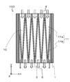
図1、2に示すように、粒子状物質の測定装置用部品100は、内部に流路空間10を有する基部1と、流路空間10の内部に設けられたフィルタ部2とを備えている。流路空間10がフィルタ部2で複数に区切られて、複数の流路11が形成されている。図3に示すように、粒子状物質の測定装置用部品100は、さらに、基部1に静電容量形成用の一対の電極3を備えている。粒子状物質の測定装置用部品100は、例えば、ディーゼルエンジンから排出される排気ガス中の粒子状物質の量を測定するために用いられる。
基部1は、ガスの流れる流路11(流路空間10)を形成するための部材である。基部1は、例えば、アルミナ等の絶縁性のセラミックスから成る。基部1は、例えば、内部に1つまたは複数の流路空間10を有している。図1に示す粒子状物質の測定装置用部品100においては、基部1は、外形が直方体形状であって、内部に2つの流路空間10を有している。流路空間10は、基部1の主面の長手方向に沿って伸びている。それぞれの流路空間10はフィルタ部2で複数に区切られており、区切られた空間の1つ1つが流路11である。2つの流路空間10は基部1の厚み(高さ)方向に配列されている。基部1は、例えば、主面の長手方向の長さ、開口を有する側面間の長さ(奥行き、y軸方向の長さ)を40mmに、短手方向の長さ、開口を有さない側面間の長さ(幅、x軸方向の長さ)を10mmに、高さ(厚み、z軸方向の長さ)を5mmに、設定できる。
流路空間10は、基部1の1つの側面からこれに対向する位置にある側面にかけて延びている。流路空間10は、基部1の1つの側面と、これに対向する位置にある側面とに開口している。そして、流路11もまた、基部1の1つの側面と、これに対向する位置にある側面とに開口している。この2つの開口のうちの一方がガスの流入する流入口4であり、他方はガスが流路11から流出する流出口5である。なお、図2においては、白抜き矢印でガスの流れを示している。また、流路空間10は、幅(x軸方向の長さ)を8mmに、高さ(底面と天井面との間隔、z軸方向の長さ)を1.2mmに設定できる。流路空間10の長さ(y軸方向の長さ)は、基部1の長さと等しく、40mmに設定できる。
フィルタ部2は、ガス中の粒子状物質を捕集するための部材である。図2および図3に示すように、フィルタ部2は、流路空間10の内部に設けられている。図2に示すように、本開示の粒子状物質の測定装置用部品100においては、フィルタ部2は板状であって、基部1の流路空間10を、流路空間10の幅方向に複数の領域に区切るように複数設けられている。そして、フィルタ部2は、流路空間10の長さ方向(y軸方向)に対して傾斜して配置されているものを含んでいる。図2に示す例においては、すべてのフィルタ部2が流路空間10の長さ方向(y軸方向)に対して傾斜して配置されている。流路空間10の長さ方向は流入口4から流出口5へ向かう方向である。本開示の粒子状物質の測定装置用部品100は、1つの流路空間10につき5つのフィルタ部2が設けられている。5つのフィルタ部2は、それぞれが並行に配列されている。フィルタ部2は、多孔質セラミックスから成る。多孔質セラミックスとしては、例えば、多孔質アルミナが挙げられる。フィルタ部2が多孔質アルミナから成ることによって、流路11を流れるガスがフィルタ部2を通過できるようになっている。このとき、フィルタ部2は、ガス中に含まれる粒子状物質の一部を捕集する(堆積させる)ことができる。そして、フィルタ部2が流路空間10の長さ方向に対して傾斜して配置されていることから、排気管内を流れてきた排気ガスの流れ方向に対して流路空間10の長さ方向が平行になるように粒子状物質の測定装置用部品100を配置すると、フィルタ部2はガスの流れに対して斜めになる。そのため、ガスがフィルタ部2内に流入しやすくなり、ガスに含まれる粒子状物質を捕集しやすくなって、粒子状物質の検知感度の高いものとなる。
フィルタ部2で区切られて設けられる流路11は、幅(フィルタ部2間の長さ)を1.2mmに、高さ(底面と天井面との間隔)を流路空間10と同じく1.2mmに設定できる。フィルタ部2の寸法は、例えば、基部1の幅方向に沿った長さを0.3mmに、基部1の厚み方向に沿った長さを流路11の底面と天井面との間隔と等しく1.2mmに、基部1の長さ方向に沿った長さを40mmに設定できる。フィルタ部2の流路空間10の長さ方向(y軸方向)に対する傾斜角度θは、例えば、3°~10°に設定すればよい。
図4および図5に示す例においては、図2に示す例に対して、隣り合う一対のフィルタ部2間に、一端部が一方のフィルタ部2の流入口4側の端部に繋がり、他端部が他方のフィルタ部2の流出口5側の端部に繋がっているフィルタ部2が設けられている。言い換えれば、フィルタ部2がジグザグ形状であり、折れ曲がり部が流入口4と流出口5とに交互に位置している。これにより、流路11は、フィルタ部2によって、ガスが流入する流入口4に繋がる第1の流路11aと、ガスが流出する流出口5に繋がる第2の流路11bとに分断されている。そして、第1の流路11aは流入口4から長さ方向に向かうにつれて幅が小さくなっており、第2の流路11bは流出口5へ長さ方向に向かうにつれて幅が大きくなっている。
このような構成により、流入口4から第1の流路11aに流入したガスの全てがフィルタ部2を通過し、第2の流路11b内を流れて流出口5から流出することになる。よって、粒子状物質の捕集効率がより向上し、粒子状物質の検知感度がより向上する。従来の粒子状物質の測定用部品は、開口の一部を閉塞部材で閉塞していたのに対して、流入口4および流出口5を閉塞していない。フィルタ部2の流入口4および流出口5において繋がっている部分(ジグザグ形状のフィルタ部2の折れ曲がり部)が閉塞部材を兼ねている。流入口4および流出口5が閉塞されていないため、流路空間10の開口面積に対する流入口4および流出口5の面積の比率が大きいものとなる。そのため、粒子状物質を含む排気ガスの流入量が大きいものとなり、粒子状物質の捕集効率の高いものとなる。そして、より小型の粒子状物質の測定装置用部品100とすることができる。
図4に示す例は、流路空間10の長さ方向に対して傾斜して配置されているフィルタ部2と、流路空間10の長さ方向に対して沿って(平行に)配置されているフィルタ部2とを有しており、これらが交互に配置されている。これに対して、図5に示す例の粒子状物質の測定装置用部品においては、すべてのフィルタ部2が流路空間10の長さ方向に対して傾斜して配置されている。隣り合うフィルタ部2は、互いに異なる方向に傾斜している。すべてのフィルタ部2が流路空間10の長さ方向に対して傾斜しているので、フィルタ部2の長さを長くでき、粒子状物質の捕集効率がさらに向上し、粒子状物質の検知感度がより向上する。なお、図4および図5に示す例においては、流路空間10の幅方向の最外部にもフィルタ部2が配置されており、基部1の流路空間10に面する内面を覆っている。このような構成によって、粒子状物質をより多く捕集することができる。図5に示す例の粒子状物質の測定装置用部品においては、すべてのフィルタ部2が流路空間10の長さ方向に対して傾斜して配置されている、と上記したが、この場合のすべてのフィルタ部2は、基部1の内面を覆うフィルタ部以外のすべてのフィルタ部を指している。
図4および図5に示す例では、第1の流路11aおよび第2の流路11bの平面視の形状、第1の流路11aおよび第2の流路11bの底面と天井面の形状は三角形である。これに対して、図6に示す例の粒子状物質の測定装置用部品100においては、第1の流路11aの形状は台形である。図5に示す例の三角形状の第1の流路11aにおける、流出口5側の角部を隅切りしたような形状である。流出口5側の折れ曲がり部が2段階に折れ曲がっていて、折れ曲がり部に流路空間10の幅方向に延びる部分を有しているともいえる。このような構成であると、フィルタ部2の流入側の第1の流路11aに面する部分の面積を増やすことができるので、より多くの粒子状物質を捕集することができる。粒子状物質の捕集効率がさらに向上し、粒子状物質の検知感度がより向上する。また、この角部が鈍角になるので、角部を起点としたフィルタ部2の割れが発生し難くなる。この点では、第2の流路11bにおいても同様に、三角形の第2の流路11bの流入口4側の角部を隅切りした形状、台形とするとよい。この場合には、粒子状物質の捕集効率の観点から、図6に示す例の粒子状物質の測定装置用部品100と同様に、第1の流路11aの幅を第2の流路11bの幅より大きくするのがよい。
図7に示す例の粒子状物質の測定装置用部品100は、図5に示す例の三角形状の第1の流路11aにおける、流出口5側の角部を丸めたような形状である。言い換えれば、ジグザグ形状のフィルタ部2の折れ曲がり部の、流路11(第1の流路11a)側の角部を丸めたものである。図6に示す例の粒子状物質の測定装置用部品100における、第1の流路11aの流出口5側の角部を丸めた形状ともいえる。そのため、同様にフィルタ部2の流入側の第1の流路11aに面する部分の面積を増やすことができるので、より多くの粒子状物質を捕集することができ、粒子状物質の捕集効率がさらに向上する。粒子状物質の検知感度がより向上する。そして、角部を有していないので、角部を起点としたフィルタ部2の割れがより発生し難くなる。この点では、第2の流路11bにおいても同様に、三角形の第2の流路11bの流入口4側の角部を丸めた形状とするとよい。この場合にも同様に、粒子状物質の捕集効率の観点から、第1の流路11aの幅を第2の流路11bの幅より大きくするのがよい。なお、図7に示す例の粒子状物質の測定装置用部品100においては、フィルタ部2の流路空間10の幅方向の最も外側に位置する部分は、基部1の流路空間10に面する内面を覆っており、流路11(第1の流路11a)側の面が流路空間10の長さ方向に対して傾斜している。この部分も、流路空間10の長さ方向に対して傾斜して配置されているという。
ここで、本開示の粒子状物質の測定装置用部品100においては、基部1の流路11の壁面がフィルタ部2の表面よりも緻密である。これにより、基部1の流路11の壁面に粒子状物質を堆積させにくくするとともに、フィルタ部2の表面に粒子状物質を堆積させやすくすることができる。これらの結果、粒子状物質の堆積をフィルタ部2に集中させやすくできるので、粒子状物質の堆積量と測定値との間のリニアリティを高めることができる。その結果、粒子状物質の測定装置用部品100の測定精度を向上させることができる。
基部1の流路11の壁面がフィルタ部2の表面より緻密であることは、例えば、以下の方法で確認できる。具体的には、基部1の流路11の壁面およびフィルタ部2の表面を走査型電子顕微鏡(SEM)を用いて観察する。そして、得られたSEM画像に画像処理を施し、表面の気孔率を求める。結果、気孔率が小さい方をより緻密であると見なすことができる。基部1の流路11の壁面の気孔率は、例えば、3%以下に設定できる。フィルタ部2の表面の気孔率は、例えば、40~70%に設定できる。なお、ここでいう流路11の壁面とは、流路11のうちガスに面する基部1の内表面の全体を意味している。すなわち、天井面および底面がここでいう壁面に含まれる。
基部1の流路11の壁面の気孔率を、3%以下にすることによって、基部1の内部に粒子状物質が入りにくくすることができる。その結果、粒子状物質が電極3に付着してしまうおそれを低減できるので、粒子状物質が電極3に付着することによって電極3間の静電容量を正しく測定することができなくなってしまうおそれを低減できる。その結果、粒子状物質の測定装置用部品100の測定精度をさらに向上できる。
基部1およびフィルタ部2は一体的に形成されている。基部1およびフィルタ部2が一体的に形成されていることによって、粒子状物質の測定装置用部品100の長期信頼性を向上できる。具体的には、基部1およびフィルタ部2が別々に形成された後に接合されているような場合には、例えば、基部1およびフィルタ部2の界面から剥がれが生じるようなおそれがある。特に、接合に接合材等を用いている場合には、接合材が劣化することによって、フィルタ部2を基部1に正しく固定することができなくなるおそれがある。これに対して、基部1およびフィルタ部2を一体的に形成(焼成)することによって、基部1およびフィルタ部2の界面から劣化が生じるおそれを低減できる。
特に、基部1およびフィルタ部2が同じセラミックスから成ることによって、基部1およびフィルタ部2の熱膨張率を近づけることができる。これにより、ヒートサイクル下における粒子状物質の測定装置用部品100の長期信頼性を向上できる。ここでいう、「同じセラミックスから成る」とは、基部1およびフィルタ部2を構成するセラミックスの主成分(80質量%以上を占める成分)が同じであることを意味している。
本開示の粒子状物質の測定装置用部品100においては、基部1およびフィルタ部2がアルミナから成る。アルミナは、安価に製造できることに加えて、下記に示すように表面の気孔率の調整が容易である。
気孔率が3%以下の表面を有する基部1、および、気孔率が40~70%程度の表面を有するフィルタ部2は、例えば、以下の方法で一体的に形成できる。具体的には、基部1となる部分については、アルミナ粉末を93質量%および樹脂バインダを7質量%含むセラミックペーストを用いる。また、フィルタ部2となる部分については、アルミナ粉末を55質量%、造孔材を38質量%および樹脂バインダを7質量%含むセラミックペーストを用いる。これらのセラミックペーストをドクターブレード法を用いて所定の形状のグリーンシートに加工する。このとき、グリーンシート上に導電性ペーストを印刷することによって、静電容量形成用の電極3を形成することができる。そして、これらのグリーンシートを一軸プレス機を用いて加圧積層する。必要に応じて表面の加工を行なった後に、1500℃で焼成することによって、上記の気孔率のフィルタ部2および基部1を形成することができる。
フィルタ部2の寸法は、例えば、基部1の幅方向に沿った長さを0.3mmに、基部1の厚み方向に沿った長さを流路11の底面と天井面との間隔と等しく1.2mmに、基部1の長さ方向に沿った長さを40mmに設定できる。
電極3は、静電容量を形成するための部材である。図3に示すように、電極3は、基部1にフィルタ部2を挟むように対になって設けられている。より具体的には、本開示の粒子状物質の測定装置用部品100のように、流路11が複数設けられている場合には、それぞれの流路11に位置するフィルタ部2を挟むように電極3が設けられている。電極3は、例えば、複数のフィルタ部2を跨って覆うように設けられていてもよいし、フィルタ部2の1つ1つに対応するように設けられていてもよい。そして、図3に示すように、本開示の粒子状物質の測定装置用部品100のように流路11が上下方向に2つ設けられている場合には、電極3は、上側の流路11の上方、上側の流路11と下側の流路11との間および下側の流路11の下方に位置していてもよい。上側の流路11と下側の流路11との間に位置している電極3は、上側の流路11の上方の電極3との間で静電容量を形成することができ、また、下側の流路11の下方の電極3との間でも静電容量を形成することができる。
フィルタ部2を挟む一対の電極3の間には静電容量が形成される。フィルタ部2に粒子状物質が捕集されると、一対の電極3の間の静電容量が変化する。この静電容量の変化を外部の検出装置で検知することによって、フィルタ部2に捕集された粒子状物質の堆積量を測定することができる。
本開示の粒子状物質の測定装置用部品100においては、電極3が基部1に埋設されている。これにより、電極3がガスによる腐食等の影響を受けるおそれを低減できる。また、電極3の表面に粒子状物質等が付着するおそれを低減できるので、粒子状物質の測定装置用部品100の測定精度を向上させることができる。なお、本開示の粒子状物質の測定装置用部品100においては、電極3が基部1の内部に設けられている(埋設されている)が、これに限られない。具体的には、電極3の設けられる位置は、例えば、基部1の外表面(流路11の壁面以外の面)であってもよい。
図8に示すように、本開示の粒子状物質の測定装置用部品100においては、電極3は、例えば、線状の配線パターンを有するとともに、フィルタ部2に沿って設けられている。このように、電極3がフィルタ部2に沿って設けられていることによって、フィルタ部2に捕集された粒子状物質の量と電極3間の静電容量の変化と間のリニアリティを向上させることができる。これは、電極3がフィルタ部2に沿って設けられていることによって、フィルタ部2以外(例えば、流路11の壁面)に付着した粒子状物質によって静電容量が変化することを低減できるためである。なお、電極3の平面視したときの形状は、線状に限られず、例えば、円形状であってもよいし、矩形状であってもよい。
また、電極3を線状の配線パターンにすることによって、電極3を円形状または矩形状にする場合と比較して抵抗値を大きくすることができる。そのため、この電極3に高い電圧を加えることによってヒータとして機能させることもできる。これにより、フィルタ部2に捕集された粒子状物質を加熱により除去することができる。
特に、図9に示す例のように、電極3が線状の配線パターンを有するとともに、基部1のうちフィルタ部2を挟む領域およびフィルタ部2を挟まない領域に設けられており、平面視したときに、電極3のうちフィルタ部2を挟まない領域に位置する部分が、フィルタ部2を挟む領域に位置する部分よりも幅が狭くなっていてもよい。これにより、電極3のうちフィルタ部2を挟む領域に位置する部分の幅を確保して電極3間の静電容量を良好に形成しつつ、電極3のうちフィルタ部2を挟まない領域に位置する部分の幅を狭くすることによって、抵抗値を大きくできる。これにより、静電容量形成用の電極3として有効に機能させつつも、ヒータとしても有効に機能させることができる。
図8および図9に示す例においては、電極3の端部は、基部1の幅方向(x軸方向)において流路11の外側に位置する基部1へ引き出された引き出し部3aを有している。この引き出し部3aからさらに基部1の外表面へ引き出され、外部の装置と電気的に接続される。例えば、引き出し部3aで電気的に接続され、基部1を貫通して基部1の上面に引き出される貫通導体(不図示)を備えている。基部1の上面には端子電極(不図示)が設けられており、貫通導体が電気的に接続されている。この端子電極と外部の検出装置とを電気的に接続することができる。
図8および図9に示す例においては、フィルタ部2を挟む一対の電極3のそれぞれは、複数のフィルタ部2のそれぞれに沿って設けられた部分の端部同士を接続して蛇行したミアンダ形状の1本の線状の配線パターンとなっている。そして、その1つ電極の端部が基部1の外表面に引き出されており、1対の電極3のそれぞれは、一系統の配線となっている。これに対して、図10および図11に示す例では、1対の電極3のそれぞれは、2つのミアンダ形状の線状の配線パターンで構成され、2系統の配線となっている。図10に示す例では、2つの配線パターンは流路11の幅方向(x軸方向)に並んで配置されており、図11に示す例では、2つの配線パターンは流路11の長さ方向(y軸方向)に並んで配置されている。
このように、フィルタ部2を挟んで配置されている一対の電極3のそれぞれが2系統の配線となっていると、一方の系統の電極3で粒子状物質を検知しながら、他方の系統の電極3で捕集された粒子状物質を除去することができる。そのため、粒子状物質の除去のために粒子状物質の検知を停止することなく、連続して粒子状物質の検知を行なうことができる。図10および図11に示す例においては、フィルタ部2を挟んで配置されている一対の電極3のそれぞれが2系統の配線となっているが、複数系統であればよいので、3系統以上の配線であってもよい。
電極3としては、例えば、白金またはタングステン等の金属材料を用いることができる。また、電極3を線状の配線パターンにした場合には、例えば、幅を2mm、長さを38mm、厚みを30μmに設定できる。
上述の開示の粒子状物質の測定装置用部品100においては、基部1が内部に流路11を有するような形状であったが、これに限られない。具体的には、例えば、図12に示すように、セラミックスから成る板状の部材であって主面が対向するように並置された一対の基部1と、一対の基部1の間の流路空間10を区切って流路11を形成するように設けられた多孔質セラミックスから成るフィルタ部2と、一対の基部1にそれぞれ設けられておりフィルタ部2を挟むように設けられた静電容量形成用の一対の電極3とを備えていてもよい。そして、図2、4~7に示したように、フィルタ部2が、流路空間10の長さ方向に対して傾斜して配置されているものを含むものであってもよい。
別の粒子状物質の測定装置用部品100においては、基部1と基部1との間の流路空間10をフィルタ部2で区切ることによって流路11が形成されている。この流路11にガスを流すことによって粒子状物質をフィルタ部2で捕集するとともに、電極3間の静電容量の変化を検知することによって粒子状物質の量を測定することができる。このような粒子状物質の測定装置用部品100においても、上述の粒子状物質の測定装置用部品100と同様に、測定精度を向上できる。
より具体的には、図12に示す粒子状物質の測定装置用部品100においては、3つの基部1が2つの流路空間10を空けて並んで設けられており、この2つの流路空間10にそれぞれ7つずつのフィルタ部2が設けられている。基部1の数は2つでも3つ以上であってもよく、また、フィルタ部2の数も適宜変更することができる。
図12に示す粒子状物質の測定装置用部品100では、フィルタ部2が側壁を兼ねているが、外側のフィルタ部2の外にフィルタ部2に接する基部1を側壁として設けてもよい。これは、図3に示す粒子状物質の測定装置用部品100において、外側のフィルタ部2が基部1の側壁に接するように配置されたものと同様になる。このようにすることで、粒子状物質の測定装置用部品100の剛性が向上し、比較的強度の小さいフィルタ部2が露出する面積を小さくすることができるので、熱応力による変形や、外力による損傷を抑えることができ、信頼性の高いものとなる。また、流路11に面する壁面は全てフィルタ部2となり、捕集効率がより高く感度のよいものとなる。
図13~図15に示す粒子状物質の測定装置用部品100においては、互いにポーラス度が異なる複数のフィルタ2を有している。粒子状物質の粒度分布を知ることのできる粒子状物質の測定装置用部品100や長時間連続して粒子状物質の捕集が可能で長寿命な粒子状物質の測定装置用部品100のような、より付加価値の高いものとすることができる。
具体的には、図13に示す例では、多孔質セラミックスから成るフィルタ部2は、気孔の大きさ、気孔径が異なる3種類のフィルタ部2a,2b,2cを有している。図13に示す例においては、相対的に気孔径の大きい第1のフィルタ部2aと気孔径の小さい第3のフィルタ部2cとこれらの中間の気孔径の第2のフィルタ部2bとを有している。
気孔径が異なる複数のフィルタ部2a,2b,2cを有していることから、それぞれのフィルタ部2a,2b,2cで捕集される粒子状物質は、それぞれ互いに平均粒径が異なるものとなる。そのため、気孔径が異なる複数のフィルタ部2a,2b,2cのそれぞれを挟む電極3で検出される静電容量から捕集された粒子状物質の粒度分布が分かり、例えば、粒子状物質を含む排気ガスを排出するエンジンにおける燃焼状態や、粒子状物質の測定装置用部品100の上流に位置するPMフィルタの状態を推測することができる。
また、図13に示す例においては、気孔径が異なる複数のフィルタ部2a,2b,2cは気孔径の大きさの順に配列されている。具体的には、図13に示す例では、図面の上下方向(z軸方向)で3段の流路空間10(流路11)が配列されており、上段には第1のフィルタ部2aが配置され、中段には第2のフィルタ部2bが配置され、下段には第3のフィルタ部2cが配置されている。すなわち、各段で同じ気孔径のフィルタ部2が図面の左右方向(流路空間10および基部1の幅方向、x軸方向)に一列に配置されている。このように配列すると、同じ気孔径のフィルタ部2を挟む電極3を並べて配置することができ、これらを図13に示す例のように1つにまとめることができる。
フィルタ部2の気孔径の大きさの種類は3つに限られず、2つでもよいし4つ以上であってもよい。また、図13に示す例においては、同じ気孔径のフィルタ部2は基部1の幅方向(x軸方向)に一列に配列されているが、複数の基部1の配置方向(z軸方向)に一列に配列してもよい。あるいは、ランダムに配列してもよいが、上記のように一列に配列してもよい。
なお、ここでいう気孔径は平均気孔径である。気孔径は、フィルタ部2の表面または断面のSEM画像を撮影し、画像解析によってこのSEM画像の範囲内の気孔について平均気孔径を算出すればよい。SEMの倍率は100倍で、1.0mm×1.3mmの視野のSEM画像を用いて行なえばよい。
フィルタ部2の気孔径は1μm~60μmであり、フィルタ部2が上記の例のように気孔径の異なる3種類のフィルタ部2a,2b,2cを有する場合であれば、例えば、第1のフィルタ部2aの気孔径は10μm~60μm、第2のフィルタ部2bの気孔径は5μm~30μm、第3のフィルタ部2cの気孔径1μm~15μmとすればよい。
また、図14および図15に示す例では、多孔質セラミックスから成るフィルタ部2は、気孔率が異なる2種類のフィルタ部2d,2eを有している。図14および図15に示す例においては、相対的に気孔率の大きい第4のフィルタ部2dと気孔率の小さい第5のフィルタ部2eとを有している。そして、流路空間10の長さ方向に垂直な断面視において、外側に位置するフィルタ部2の気孔率が、内側に位置するフィルタ部2の気孔率より大きい。なお、ここでいう「外側に位置する」とは、図14に示すように上下方向における外側であってもよい。また、「外側に位置する」とは、図15に示すように、流路空間10の幅方向における外側であってもよい。また、「外側に位置する」とは、上下方向および幅方向の全体における外側であってもよい。
流路空間10の長さ方向に垂直な断面視において、外側に第4のフィルタ部2dが配置され、内側に第5のフィルタ部2eが配置されている。図14に示す例においては、図面の上下方向(複数の基部1の配置方向、z軸方向)の外側に第4のフィルタ部2dが配置され、内側に第5のフィルタ部2eが配置されている。図面の上下方向(複数の基部1の配置方向、z軸方向)に3段の流路空間10が配列されており、上段および下段の流路空間10に第4のフィルタ部2dが配置され、中段の流路空間10に第5のフィルタ部2eが配置されている。図15に示す例においては、図面の左右方向(流路空間10および基部1の幅方向、x軸方向)の外側に第4のフィルタ部2dが配置され、内側に第5のフィルタ部2eが配置されている。上下方向(複数の基部1の配置方向、z軸方向)で3段の流路空間10が配列されており、それぞれの流路空間10に左右方向(流路空間10および基部1の幅方向、x軸方向)に6つのフィルタ部2が配置されている。この6つのフィルタ部2のうち、左右それぞれの2つが第4のフィルタ部2dであり、これらの間に位置する2つが第5のフィルタ部2eである。
粒子状物質を含むガスが粒子状物質の測定装置用部品100内の流路空間10(流路11)を流れる際には、流路空間10の中心部(流路空間10の長さ方向に垂直な断面視における内側の領域)を流れるガスの流量が、流路空間10の外周部(流路空間10の長さ方向に垂直な断面視における外側の領域)を流れるガスの流量より大きくなる傾向がある。そのため、内側のフィルタ部2の方が外側のフィルタ部2より多くの粒子状物質を捕集することになり、粒子状物質の詰まりも早くなってしまう。粒子状物質の詰まりが早いと、ヒータ加熱で粒子状物質を除去する再生を行なう頻度が高くなるので、粒子状物質の測定装置用部品100の劣化も早くなってしまう。これに対して、上記のように、流路の長さ方向に垂直な断面視において、外側に位置するフィルタ部2(第4のフィルタ部2d)の気孔率が、内側に位置するフィルタ部2(第5のフィルタ部2e)の気孔率より大きいと、気孔率の大きいフィルタ部2(第4のフィルタ部2d)の方にガスが流れやすくなり、流路の長さ方向に垂直な断面における、位置によるガス流量差が小さくなる。そのため、内側のフィルタ部2だけが早く粒子状物質により詰まってしまうことがないので、長時間の連続した粒子状物質の捕集が可能で、長寿命な粒子状物質の測定装置用部品100となる。
図14および図15においては、それぞれ上下方向の外側、左右方向の外側に位置するフィルタ部2(第4のフィルタ部2d)の気孔率が、内側に位置するフィルタ部2(第5のフィルタ部2e)の気孔率より大きいものであるが、これらを組みわせた、上下左右方向の外側、断面における外周部に位置するフィルタ部2の気孔率が、上下左右方向の内側、断面における中心部に位置するフィルタ部2の気孔率より大きいものであってもよい。基部1とフィルタ部2とが上下方向に交互に配置されている場合であれば、図14に示す例のように、上下方向の外側に第4のフィルタ部2dが配置され、内側に第5のフィルタ部2eが配置されている構造が、後述するような製造方法で容易に製造することができるのでよい。
フィルタ部2の気孔率を比較するための、気孔率の測定方法としては、例えば、水銀圧入法(JIS規格R1655:2003)、SEM画像の画像解析などが挙げられる。SEM画像の画像解析は、フィルタ部2の断面のSEM画像を撮影し、画像解析によってこのSEM画像の範囲内における気孔の面積率を算出することで行なうことができる。例えば、SEMの倍率は100倍で、1.0mm×1.3mmの視野のSEM画像を用いて行なえばよい。
フィルタ部2の気孔率が40~70%である場合には、相対的に気孔率の大きいフィルタ部2dおよび気孔率の小さいフィルタ部2eのそれぞれの気孔率は、50~70%および40~60%とすればよい。
以上の粒子状物質の測定装置用部品100は、流路11は、基部1の1つの側面からこれに対向する位置にある側面にかけて延びている例で説明したが、これに限られるものではない。例えば、図16に示す例のように、流路空間10は、その一端が基部1の1つの側面に開口するとともに、他端が基部1の一端に位置する面(下面)に開口していてもよい。図16に示す例においては、流入口4が基部1の上面に設けられ、流路11は基部1の内部において、2段の流路11に別れて基部1の側面(図面の下側の側面)に設けられた流出口5まで延びている。それぞれの流路11内にフィルタ部2が設けられ、第1の流路11aと第2の流路11bとに区切られている。ガスの流れは白抜き矢印で示しており、ガスは基部1の上面に設けられた流入口4から流入し、基部1の側面に設けられた流出口5から流出する。あるいは、基部1の対向する2つの側面と基部1の一端部に位置する面(下面)とに開口していてもよい。
以上のような、セラミックスから成る緻密な基部1と多孔質セラミックスから成るフィルタ部2とが一体的に形成されている粒子状物質の測定装置用部品100の製造方法は、例えば、複数の第1のセラミックグリーンシート12を準備する工程と、複数の第2のセラミックグリーンシート22を準備する工程と、第1のセラミックグリーンシート12に電極層32を形成する工程と、第2のセラミックグリーンシート22に貫通孔112を形成する工程と、電極層32が形成された第1のセラミックグリーンシート12と貫通孔112が形成された第2のセラミックグリーンシート22を積層して積層体102を形成する工程と、積層体102を焼成する工程とを備える。
このような製造方法によれば、セラミックスから成る緻密な基部1と多孔質セラミックスから成るフィルタ部2とが一体的に形成されている、上記のような粒子状物質の測定装置用部品100を製造することができる。
図17は、粒子状物質の測定装置用部品の製造方法を工程毎に示す模式図である。図17は、図12に示す例のような粒子状物質の測定装置用部品100において、一対の基部1の間に配置されたフィルタ部2を7つから6つにしたものを製造する工程を示すものである。まず、図17(a)に示す例のように、複数の第1のセラミックグリーンシート12および複数の第2のセラミックグリーンシート22を準備する。第1のセラミックグリーンシート12は、後の焼成工程において焼結して基部1となる部分であり、第2のセラミックグリーンシート22は、同様にフィルタ部2となる部分である。緻密なセラミックスから成る基部1に対して、フィルタ部2は多孔質セラミックスから成るものである。そのため第2のセラミックグリーンシート22は、第1のセラミックグリーンシート12に対して、後の焼成工程において焼結した際に気孔が多くなる(気孔率が大きくなる)ものである。具体的には、第2のセラミックグリーンシート22は、第1のセラミックグリーンシート12と比較して、焼成工程において焼結する際に、気孔となる成分を多く含むものである。具体的には、有機バインダ成分が多いもの、造孔材を含んでいるものなどである。あるいは、焼結性を低下させて気孔を増やすために、焼結助剤成分が少ないものである。
気孔径や気孔率の調整が容易である点で、造孔材を用いるのがよい。造孔材は、後の焼成工程において焼失する粒子状のものである。造孔材としては、例えば、アクリル樹脂ビーズ(メタクリル酸エステル系共重合物)、カーボン粉末、結晶セルロースが挙げられる。造孔材の粒径は、フィルタ部2の気孔径の1倍~1.2倍のものを用いればよい。上記したような、気孔径が1μm~60μmのフィルタ部2を作製する場合であれば、平均粒径が1μm~72μmの造孔材を用いればよい。気孔率の調整は、造孔材の粒径と量によって調整することができる。
第1のセラミックグリーンシート12は、基部1がアルミナ質セラミックスから成る場合であれば、まず、アルミナ粉末および焼結助剤(SiO2,MgO,CaO等の粉末)にアクリル系樹脂などの有機バインダ,トルエンやアセトン等の有機溶剤や水などの溶媒を混合してスラリーを作製する。このスラリーを用いてドクターブレード法等の成膜方法によってシート状にすればよい。第2のセラミックグリーンシート22は、第1のセラミックグリーンシート12用のスラリーに造孔材を加えたスラリーを作製すればよい。第2のセラミックグリーンシート22は、第1のセラミックグリーンシート12に対して造孔材を含むものとなる。
フィルタ部2が気孔径の異なるものを有する場合は、例えば、第2のセラミックグリーンシート22用のスラリーに加える造孔材として、平均粒径が互いに異なるものを用いて、含まれる造孔材の平均粒径が異なる、複数種の第2のセラミックグリーンシート22を作製すればよい。フィルタ部2が気孔率の異なるものを有する場合は、例えば、第2のセラミックグリーンシート22用のスラリーに加える造孔材量を互いに異ならせて、含まれる造孔材の平均粒径が異なる、複数種の第2のセラミックグリーンシート22を作製すればよい。
次に、図17(b)に示す例のように、第1のセラミックグリーンシート12に電極層32を形成する。電極層32は後の焼成工程において焼結して電極3となるものである。電極層32の形成は、電極3の主成分となる白金またはタングステン等の金属材料を主成分とする金属ペーストを第1のセラミックグリーンシート12上に塗布することで行なえばよい。金属ペーストは、金属材料の粉末に樹脂バインダおよび溶媒を加えて混練して作製することができる。金属ペーストをスクリーン印刷法等により、電極3の配線パターン形状に塗布すればよい。このとき、第1のセラミックグリーンシート12の面のうち片側だけに電極層32を形成する。
また、図17(c)に示す例のように、第2のセラミックグリーンシート22に貫通孔112を形成する。貫通孔112は流路11となる部分である。第2のセラミックグリーンシート22に、金型を用いた打ち抜き加工やレーザー加工によって貫通孔112を形成すればよい。
次に、図17(d)に示す例のように、電極層32が形成された第1のセラミックグリーンシート12と貫通孔112が形成された第2のセラミックグリーンシート22を積層して積層体102を形成する。図17(d)に示す例では、3つの基体1となる部分はそれぞれ2層の第1のセラミックグリーンシート12が積層されて形成され、フィルタ部2となる部分は2層の第2のセラミックグリーンシート22が積層されて形成されている。いずれも、1層や3層以上のセラミックグリーンシートを用いても構わない。
図17(d)に示す例は、図12に示す例のような電極3が基部1に埋設された粒子状物質の測定装置用部品100を作製する場合の積層体102であるので、電極層32は2層の第1のセラミックグリーンシート12の層間に位置している。電極層32を形成した第1のセラミックグリーンシート12の上に電極層32を形成していない第1のセラミックグリーンシート12を積層している。
図3に示す例のような粒子状物質の測定装置用部品100を作製する場合には、電極層32を形成した第1のセラミックグリーンシート12の上に電極層32を形成していない第1のセラミックグリーンシート12を重ねた上に、第2のセラミックグリーンシート22のフィルタ部2となる部分のみを重ね、さらにその周りを囲むように枠状の第1のセラミックグリーンシート12を重ねればよい。
積層体102を形成するには、電極層32が形成された第1のセラミックグリーンシート12と貫通孔112が形成された第2のセラミックグリーンシート22とを重ねて、一軸加圧プレス等で加圧して圧着することで一体化させればよい。
貫通孔112に後の焼成工程で焼失する樹脂等を充填しておくと、第1のセラミックグリーンシート12における貫通孔の上下に位置する部分の変形を抑えることができる。
そして、積層体102を焼成することで、上記のような、セラミックスから成る緻密な基部1と多孔質セラミックスから成るフィルタ部2とが一体的に形成されている粒子状物質の測定装置用部品100となる。焼成温度は、基部1およびフィルタ部2がアルミナ質セラミックスから成る場合であれば、1500℃~1600℃とすればよい。
貫通導体を形成するには、積層体102を作製する工程の前に、必要なセラミックグリーンシートに金型を用いた打ち抜き加工やレーザー加工によって貫通孔を形成し、この貫通孔に電極層32を形成するのと同様の導体ペーストを充填しておけばよい。
1:基部
10:流路空間
11:流路
11a:第1の流路
11b:第2の流路
2:フィルタ部
3:電極
4:流入口
5:流出口
100:粒子状物質の測定装置用部品
10:流路空間
11:流路
11a:第1の流路
11b:第2の流路
2:フィルタ部
3:電極
4:流入口
5:流出口
100:粒子状物質の測定装置用部品
Claims (10)
- セラミックスから成り内部にガスの流れる流路空間を有する基部と、前記流路空間を複数に区切って流路を形成するように前記流路空間に設けられた多孔質セラミックスから成るフィルタ部と、前記基部に前記フィルタ部を挟むように設けられた静電容量形成用の一対の電極とを備えており、
前記フィルタ部は、前記流路空間の長さ方向に対して傾斜して配置されているものを含んでいる粒子状物質の測定装置用部品。 - セラミックスから成る板状の部材であって主面が対向するように並置された一対の基部と、該一対の基部の間のガスの流れる流路空間を区切って流路を形成するように設けられた多孔質セラミックスから成るフィルタ部と、前記一対の基部にそれぞれ設けられており前記フィルタ部を挟むように設けられた静電容量形成用の一対の電極とを備えており、
前記フィルタ部は、前記流路空間の長さ方向に対して傾斜して配置されているものを含んでいる粒子状物質の測定装置用部品。 - 前記流路は、前記ガスが流入する流入口に繋がる第1の流路と、前記ガスが流出する流出口に繋がる第2の流路とを有しており、前記第1の流路は前記流入口から長さ方向に向かうにつれて幅が小さくなっており、前記第2の流路は前記流出口へ長さ方向に向かうにつれて幅が大きくなっている請求項1または請求項2に記載の粒子状物質の測定装置用部品。
- 前記電極が前記基部に埋設されている請求項1乃至請求項3のいずれかに記載の粒子状物質の測定装置用部品。
- 前記基部および前記フィルタ部が一体的に形成されている請求項1乃至請求項4のいずれかに記載の粒子状物質の測定装置用部品。
- 前記基部および前記フィルタ部が同じセラミックスから成る請求項1乃至請求項5のいずれかに記載の粒子状物質の測定装置用部品。
- 前記基部および前記フィルタ部がアルミナから成る請求項6に記載の粒子状物質の測定装置用部品。
- 前記電極が、線状の配線パターンを有するとともに、前記フィルタ部に沿って設けられている請求項1乃至請求項7のいずれかに記載の粒子状物質の測定装置用部品。
- 互いに気孔径が異なる複数の前記フィルタ部を有している請求項1乃至8のいずれかに記載の粒子状物質の測定装置用部品。
- 前記流路空間の長さ方向に垂直な断面視において、外側に位置する前記フィルタ部の気孔率が、内側に位置する前記フィルタ部の気孔率より大きい請求項1乃至9のいずれかに粒子状物質の測定装置用部品。
Priority Applications (1)
| Application Number | Priority Date | Filing Date | Title |
|---|---|---|---|
| JP2017558909A JP6711846B2 (ja) | 2015-12-28 | 2016-12-06 | 粒子状物質の測定装置用部品 |
Applications Claiming Priority (2)
| Application Number | Priority Date | Filing Date | Title |
|---|---|---|---|
| JP2015-256081 | 2015-12-28 | ||
| JP2015256081 | 2015-12-28 |
Publications (1)
| Publication Number | Publication Date |
|---|---|
| WO2017115617A1 true WO2017115617A1 (ja) | 2017-07-06 |
Family
ID=59225470
Family Applications (1)
| Application Number | Title | Priority Date | Filing Date |
|---|---|---|---|
| PCT/JP2016/086128 WO2017115617A1 (ja) | 2015-12-28 | 2016-12-06 | 粒子状物質の測定装置用部品 |
Country Status (2)
| Country | Link |
|---|---|
| JP (1) | JP6711846B2 (ja) |
| WO (1) | WO2017115617A1 (ja) |
Families Citing this family (1)
| Publication number | Priority date | Publication date | Assignee | Title |
|---|---|---|---|---|
| KR102550708B1 (ko) * | 2021-07-05 | 2023-07-03 | 국방과학연구소 | 공기 흡입식 폭발물 탐지 장치 |
Citations (6)
| Publication number | Priority date | Publication date | Assignee | Title |
|---|---|---|---|---|
| EP0225402A1 (en) * | 1985-11-05 | 1987-06-16 | Nippondenso Co., Ltd. | Porous ceramic structure |
| JP2007524786A (ja) * | 2004-02-12 | 2007-08-30 | ダイムラークライスラー・アクチェンゲゼルシャフト | パティキュレートフィルタの状態判定装置 |
| JP2009006326A (ja) * | 2002-03-29 | 2009-01-15 | Ibiden Co Ltd | セラミックフィルタおよび排ガス浄化装置 |
| US20100202934A1 (en) * | 2007-04-27 | 2010-08-12 | Wolfgang Hahnl | Exhaust gas purification device for an exhaust system |
| JP2014184387A (ja) * | 2013-03-22 | 2014-10-02 | Ngk Insulators Ltd | ハニカム構造体 |
| JP2015066517A (ja) * | 2013-09-30 | 2015-04-13 | 京セラ株式会社 | ハニカム構造体およびこれを用いたガス処理装置 |
-
2016
- 2016-12-06 WO PCT/JP2016/086128 patent/WO2017115617A1/ja active Application Filing
- 2016-12-06 JP JP2017558909A patent/JP6711846B2/ja not_active Expired - Fee Related
Patent Citations (6)
| Publication number | Priority date | Publication date | Assignee | Title |
|---|---|---|---|---|
| EP0225402A1 (en) * | 1985-11-05 | 1987-06-16 | Nippondenso Co., Ltd. | Porous ceramic structure |
| JP2009006326A (ja) * | 2002-03-29 | 2009-01-15 | Ibiden Co Ltd | セラミックフィルタおよび排ガス浄化装置 |
| JP2007524786A (ja) * | 2004-02-12 | 2007-08-30 | ダイムラークライスラー・アクチェンゲゼルシャフト | パティキュレートフィルタの状態判定装置 |
| US20100202934A1 (en) * | 2007-04-27 | 2010-08-12 | Wolfgang Hahnl | Exhaust gas purification device for an exhaust system |
| JP2014184387A (ja) * | 2013-03-22 | 2014-10-02 | Ngk Insulators Ltd | ハニカム構造体 |
| JP2015066517A (ja) * | 2013-09-30 | 2015-04-13 | 京セラ株式会社 | ハニカム構造体およびこれを用いたガス処理装置 |
Also Published As
| Publication number | Publication date |
|---|---|
| JPWO2017115617A1 (ja) | 2018-11-22 |
| JP6711846B2 (ja) | 2020-06-17 |
Similar Documents
| Publication | Publication Date | Title |
|---|---|---|
| JP6626901B2 (ja) | 粒子状物質の測定装置用部品およびその製造方法 | |
| CN107407624B (zh) | 用于检测导电和/或可极化粒子的传感器、传感器系统、用于操作传感器的方法、此类型传感器的制造方法以及此类型传感器用途 | |
| US20130283886A1 (en) | Particulate matter detection element and method of manufacturing same | |
| JP5542007B2 (ja) | 粒子状物質検出装置 | |
| JP6228018B2 (ja) | 粒子状物質検出素子、粒子状物質検出センサ並びに粒子状物質検出素子の製造方法 | |
| JP5542006B2 (ja) | 粒子状物質検出装置 | |
| JP6536507B2 (ja) | 粒子状物質検出センサ | |
| JP2012058015A (ja) | 粒子状物質検出装置 | |
| JP2012117383A (ja) | Pmセンサ及びpmセンサ製造方法 | |
| CN108369203B (zh) | 传感器元件 | |
| WO2017115617A1 (ja) | 粒子状物質の測定装置用部品 | |
| JP6920451B2 (ja) | 測定装置用部品 | |
| JP5864368B2 (ja) | 粒子状物質検出素子並びにその製造方法 | |
| JP6542913B2 (ja) | 粒子状物質の測定装置用部品 | |
| KR101652981B1 (ko) | 입자상 물질 센서 | |
| WO2016185841A1 (ja) | 粒子状物質検出センサ | |
| JPWO2019049567A1 (ja) | 微粒子検出素子及び微粒子検出器 | |
| JP6435198B2 (ja) | 粒子状物質検出センサ | |
| WO2019049568A1 (ja) | 微粒子検出素子及び微粒子検出器 | |
| WO2017047606A1 (ja) | 粒子状物質検出センサ | |
| JP2017191051A (ja) | センサ |
Legal Events
| Date | Code | Title | Description |
|---|---|---|---|
| 121 | Ep: the epo has been informed by wipo that ep was designated in this application |
Ref document number: 16881597 Country of ref document: EP Kind code of ref document: A1 |
|
| ENP | Entry into the national phase |
Ref document number: 2017558909 Country of ref document: JP Kind code of ref document: A |
|
| NENP | Non-entry into the national phase |
Ref country code: DE |
|
| 122 | Ep: pct application non-entry in european phase |
Ref document number: 16881597 Country of ref document: EP Kind code of ref document: A1 |