WO2017115506A1 - 付着物除去装置 - Google Patents
付着物除去装置 Download PDFInfo
- Publication number
- WO2017115506A1 WO2017115506A1 PCT/JP2016/078018 JP2016078018W WO2017115506A1 WO 2017115506 A1 WO2017115506 A1 WO 2017115506A1 JP 2016078018 W JP2016078018 W JP 2016078018W WO 2017115506 A1 WO2017115506 A1 WO 2017115506A1
- Authority
- WO
- WIPO (PCT)
- Prior art keywords
- gear
- cylinder
- rotating body
- cleaning liquid
- compressed air
- Prior art date
- Legal status (The legal status is an assumption and is not a legal conclusion. Google has not performed a legal analysis and makes no representation as to the accuracy of the status listed.)
- Ceased
Links
Images










Classifications
-
- G—PHYSICS
- G02—OPTICS
- G02B—OPTICAL ELEMENTS, SYSTEMS OR APPARATUS
- G02B27/00—Optical systems or apparatus not provided for by any of the groups G02B1/00 - G02B26/00, G02B30/00
- G02B27/0006—Optical systems or apparatus not provided for by any of the groups G02B1/00 - G02B26/00, G02B30/00 with means to keep optical surfaces clean, e.g. by preventing or removing dirt, stains, contamination, condensation
-
- B—PERFORMING OPERATIONS; TRANSPORTING
- B60—VEHICLES IN GENERAL
- B60S—SERVICING, CLEANING, REPAIRING, SUPPORTING, LIFTING, OR MANOEUVRING OF VEHICLES, NOT OTHERWISE PROVIDED FOR
- B60S1/00—Cleaning of vehicles
- B60S1/02—Cleaning windscreens, windows or optical devices
- B60S1/46—Cleaning windscreens, windows or optical devices using liquid; Windscreen washers
- B60S1/48—Liquid supply therefor
- B60S1/481—Liquid supply therefor the operation of at least part of the liquid supply being controlled by electric means
- B60S1/485—Liquid supply therefor the operation of at least part of the liquid supply being controlled by electric means including control systems responsive to external conditions, e.g. by detection of moisture, dirt or the like
-
- B—PERFORMING OPERATIONS; TRANSPORTING
- B60—VEHICLES IN GENERAL
- B60S—SERVICING, CLEANING, REPAIRING, SUPPORTING, LIFTING, OR MANOEUVRING OF VEHICLES, NOT OTHERWISE PROVIDED FOR
- B60S1/00—Cleaning of vehicles
- B60S1/02—Cleaning windscreens, windows or optical devices
- B60S1/54—Cleaning windscreens, windows or optical devices using gas, e.g. hot air
-
- B—PERFORMING OPERATIONS; TRANSPORTING
- B60—VEHICLES IN GENERAL
- B60S—SERVICING, CLEANING, REPAIRING, SUPPORTING, LIFTING, OR MANOEUVRING OF VEHICLES, NOT OTHERWISE PROVIDED FOR
- B60S1/00—Cleaning of vehicles
- B60S1/02—Cleaning windscreens, windows or optical devices
- B60S1/56—Cleaning windscreens, windows or optical devices specially adapted for cleaning other parts or devices than front windows or windscreens
-
- H—ELECTRICITY
- H04—ELECTRIC COMMUNICATION TECHNIQUE
- H04N—PICTORIAL COMMUNICATION, e.g. TELEVISION
- H04N23/00—Cameras or camera modules comprising electronic image sensors; Control thereof
- H04N23/80—Camera processing pipelines; Components thereof
- H04N23/81—Camera processing pipelines; Components thereof for suppressing or minimising disturbance in the image signal generation
- H04N23/811—Camera processing pipelines; Components thereof for suppressing or minimising disturbance in the image signal generation by dust removal, e.g. from surfaces of the image sensor or processing of the image signal output by the electronic image sensor
-
- H—ELECTRICITY
- H04—ELECTRIC COMMUNICATION TECHNIQUE
- H04N—PICTORIAL COMMUNICATION, e.g. TELEVISION
- H04N7/00—Television systems
- H04N7/18—Closed-circuit television [CCTV] systems, i.e. systems in which the video signal is not broadcast
Definitions
- the disclosed embodiment relates to a deposit removing device.
- a camera that is mounted on a vehicle and captures an image around the vehicle is known, and the image captured by the camera is provided to a driver, for example.
- the above-mentioned lens of the camera may be attached with deposits such as water droplets, snow and dirt due to the influence of the weather such as rain and snow.
- deposits such as water droplets, snow and dirt due to the influence of the weather such as rain and snow.
- an adhering matter removing device that ejects compressed air or the like to the lens of the camera has been proposed (for example, see Patent Document 1).
- the space occupied by the device may be increased.
- One aspect of the embodiment has been made in view of the above, and an object thereof is to provide a deposit removing device capable of saving space.
- One aspect of the embodiment is a deposit removing device that removes deposits attached to an optical sensor, and includes an air compression unit.
- the air compression unit includes a cylinder and a rotating body provided in the cylinder so as to be rotatable around a rotation shaft, and jets compressed air generated by the rotation of the rotating body to the optical sensor.
- space saving can be achieved in the deposit removal device.
- FIG. 1A is a partially transparent perspective view showing an outline of the configuration of the deposit removing apparatus.
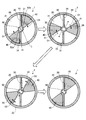
- FIG. 1B is a diagram for explaining the operation of the deposit removal apparatus.
- FIG. 2 is a perspective view showing a vehicle on which the deposit removing device is mounted.
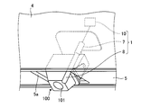
- FIG. 3A is an enlarged perspective view showing the vicinity of the camera at the rear of the vehicle.
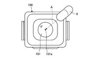
- FIG. 3B is a view of the camera when viewed from the lens side.
- FIG. 4 is a block diagram illustrating a configuration example of an attached matter removing apparatus and a camera.
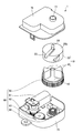
- FIG. 5 is an exploded perspective view of the deposit removing device.
- FIG. 6A is a cross-sectional view when the cylinder is cut in the horizontal direction at the intake portion.
- FIG. 6A is a cross-sectional view when the cylinder is cut in the horizontal direction at the intake portion.
- FIG. 6B is an enlarged longitudinal sectional view for explaining the configuration of the intake valve.
- FIG. 7 is an enlarged vertical sectional view showing the vicinity of the ceiling of the cylinder.
- FIG. 8A is a diagram for explaining the configuration and operation of the drive unit.
- FIG. 8B is a diagram for explaining the configuration and operation of the drive unit.
- FIG. 8C is a diagram for explaining the configuration and operation of the drive unit.
- FIG. 8D is a diagram for explaining the configuration and operation of the drive unit.
- FIG. 9 is a partially transparent perspective view showing the configuration of the deposit removal apparatus according to the second embodiment.
- 10 is a longitudinal sectional view of the deposit removing device shown in FIG. 11 is a cross-sectional view taken along line XI-XI in FIG.
- FIG. 10 is a longitudinal sectional view of the deposit removing device shown in FIG. 11 is a cross-sectional view taken along line XI-XI in FIG. FIG.
- FIG. 12 is an exploded perspective view of the deposit removing apparatus according to the third embodiment.
- FIG. 13A is a bottom view when the drive unit accommodated in the case is viewed from the bottom surface side.
- FIG. 13B is a bottom view when the drive unit accommodated in the case is viewed from the bottom surface side.
- FIG. 14A is a top view when the drive unit accommodated in the case is viewed from the top surface side.
- FIG. 14B is a top view when the drive unit accommodated in the case is viewed from the top surface side.
- FIG. 14C is a top view when the drive unit accommodated in the case is viewed from the top surface side.
- FIG. 15 is an enlarged perspective view showing a gear.
- the deposit removing apparatus is a device that is disposed at the rear of the vehicle and removes deposits attached to a camera that captures the rear of the vehicle.
- FIG. 1A is a partially transparent perspective view showing an outline of the configuration of the deposit removing apparatus 1.
- FIG. 1B is a cross-sectional view taken along the line II of FIG. 1A and is a view for explaining the operation of the deposit removing apparatus 1.
- the deposit removing apparatus 1 operates in the order of the upper left diagram, the upper right diagram, the lower left diagram, and the lower right diagram when the upper left diagram is in the initial state.
- 1A and 1B and the drawings shown in FIG. 2 and subsequent figures are all schematic views.
- the deposit removing device 1 includes an air compression unit 10.
- the air compressing unit 10 compresses air to generate compressed air, and ejects the generated compressed air to the camera 100 for the vehicle, thereby removing adhered substances such as water droplets attached to the lens of the camera 100, for example. To do.
- the conventional deposit removing device has a structure in which compressed air is generated by reciprocating the piston in the cylinder, so that the space occupied by the device may be increased.
- the shaft portion interlocking with the piston protrudes from the outer shape of the cylinder, so it is necessary to secure the operating area of the shaft portion around the cylinder, and the occupied space may increase accordingly. was there.
- the operation noise of the piston at the time of air compression may be relatively loud.
- the deposit removing device 1 is configured to save space and reduce operating noise.
- the configuration of the deposit removing apparatus 1 will be described in detail.
- the air compression unit 10 is a rotary compression mechanism. Specifically, as shown in FIG. 1A, the air compression unit 10 includes a cylinder 20, a wall part 30, a blade part 40, and a flow path part 50. In FIG. 1A, for convenience of understanding, the cylinder 20 is indicated by a two-dot chain line, and the inside of the cylinder 20 is shown through.
- the cylinder 20 is formed in a cylindrical shape, for example, and a cylinder chamber 21 is formed inside.
- the cylinder chamber 21 is provided with the wall portion 30, the blade portion 40, the flow path portion 50, and the like.
- the wall portion 30 is formed in a flat plate shape, for example, and is erected and fixed in the cylinder 20. Specifically, as shown in the upper left diagram of FIG. 1B, the wall portion 30 is formed so as to partition the cylindrical cylinder chamber 21 along the radial direction. Accordingly, the cylinder chamber 21 is divided into two cylinder chambers 21 by the wall portion 30.
- the blade portion 40 is provided in the cylinder 20 so as to be rotatable around the rotation axis C.
- the rotation axis C of the blade portion 40 is coaxial with the central axis of the cylindrical cylinder chamber 21, for example, but is not limited thereto.
- the blade portion 40 is an example of a rotating body.
- the blade portion 40 is formed, for example, in a fan shape when viewed in the rotation axis direction. Further, the blade portion 40 has a shape having a side surface 41 that faces the wall surface 31 of the wall portion 30 when it is in the initial state of the upper left diagram of FIG. 1B, in other words, when it is in the state before rotation.
- wing part 40 is not limited to an above-described shape, For example, other shapes, such as flat form similar to the wall part 30, may be sufficient.
- One blade part 40 is accommodated in the cylinder chamber 21 divided into two as described above. Accordingly, although there are a plurality of blade portions 40 (two in the illustrated example), the number of blade portions 40 can be appropriately changed according to the number of cylinder chambers 21 partitioned by the wall portion 30. .
- the two blade portions 40 are arranged so as to be rotationally symmetric when viewed from the direction along the rotation axis C.
- the flow path unit 50 is configured such that compressed air flows therein.
- the flow path portion 50 is, for example, a hollow cylindrical shape inside, and is formed in the cylinder 20 along the rotation axis C of the blade portion 40.
- the flow path part 50 is provided with the inflow port 52a into which compressed air flows in, and the outflow port 52b from which compressed air flows out.
- the inflow port 52 a is formed on the bottom surface 20 a side of the cylinder 20.
- the outlet 52 b is formed on the ceiling surface 20 b side of the cylinder 20.
- the air compression part 10 expands the space 22 (refer FIG. 1B upper right figure) between the side surface 41 and the wall surface 31 of the wall part 30 by rotation of the blade
- the outlet 52b functions as an opening through which the intake flows into the flow path portion 50
- the inlet 52a functions as an opening through which the intake of the flow path 50 flows into the space 22.
- the flow path part 50 is an example of a 1st flow path part.
- the blade section 40 is rotated in one direction around the rotation axis C by a driving section 60 (see FIG. 5) described later.
- the one direction described above is clockwise (clockwise) in the plane of FIG. 1B as indicated by an arrow D1, but is not limited to this.
- the blade portion 40 is rotated in the other direction around the rotation axis C by the drive unit 60 (see FIG. 5).
- the other direction means a direction opposite to the one direction described above.
- the other direction is counterclockwise (counterclockwise) in the plane of FIG. 1B as indicated by an arrow D2, but is not limited thereto.
- wing part 40 in one direction or the other direction in the drive part 60 is later mentioned using FIG.
- the side surface 41 of the blade portion 40 moves in a direction approaching the wall surface 31 of the wall portion 30, and thus the space 22 is compressed, that is, compressed air is generated.
- the blade portion 40 is further rotated in the other direction by the driving portion 60, and the side surface 41 returns to the initial state position facing the wall surface 31 of the wall portion 30.
- Compressed air flowing through the flow path 50 is ejected from the outlet 52b toward the camera 100 as shown in FIG. 1A. Thereby, for example, adhered matter such as water droplets attached to the lens of the camera 100 can be removed.
- the air compression part 10 is comprised so that the compressed air produced
- the air compression unit 10 can be reduced in size. Thereby, the space-saving of the deposit
- the compressed air is ejected in the direction of the rotation axis C of the blade part 40, in other words, in the direction orthogonal to the rotation direction of the blade part 40. Accordingly, the generated compressed air can be collected, and the compressed air that has been collected and has a relatively high pressure can be ejected to the camera 100.
- the flow path portion 50 is formed in the cylinder 20 along the rotation axis C of the blade portion 40.
- generated compressed air can be collected in one place of the flow-path part 50, and comparatively high-pressure compressed air can be obtained reliably and can be ejected to the camera 100.
- the vicinity of the rotation axis C of the blade portion 40 that tends to become a dead space in the cylinder 20 can be effectively used as a flow path of the compressed air, and as a result, the air compression portion 10 can be downsized.
- the flow path unit 50 includes an inflow port 52 a formed on the bottom surface 20 a side of the cylinder 20 and an outflow port 52 b formed on the ceiling surface 20 b side of the cylinder 20. Thereby, in the flow path part 50, it becomes possible to ensure the flow path length required in order to obtain comparatively high-pressure compressed air.
- the plurality of blade portions 40 are arranged so as to be rotationally symmetric. Thereby, for example, when the compressed air is generated, the impact force applied to the wall portion 30 by the blade portion 40 acts in a direction to cancel each other. Therefore, the influence on the air compression part 10 by impact force can be relieved.
- FIG. 2 is a perspective view showing the vehicle 2 on which the deposit removing device 1 is mounted.
- the object from which the deposits are removed by the deposit removing device 1 is the rear imaging camera (rear camera) 100 of the vehicle 2 here, it is not limited to this.
- it may be an optical sensor that acquires an image through a lens, for example, or acquires information about a target around the vehicle.
- various optical sensors such as a front camera that images the front of the vehicle, a side camera that images the side of the vehicle, and a radar device that detects a target around the vehicle can be targeted.
- the deposit removing device 1 and the camera 100 are installed, for example, at the upper part of the license plate 3 at the rear of the vehicle 2 and at the approximate center in the left-right direction of the vehicle 2.
- FIG. 3A is an enlarged perspective view showing the vicinity of the camera 100 at the rear of the vehicle 2 shown in FIG. 3B is a diagram when the camera 100 shown in FIG. 3A is viewed from the lens 101 side.
- a garnish 5 is attached to the vehicle back panel 4, and a camera 100 is disposed in a space between the vehicle back panel 4 and the garnish 5.
- the garnish 5 is provided with an opening 5a, and the camera 100 is arranged so that the lens 101 portion is exposed outward from the opening 5a.
- the deposit removing device 1 includes a hose 7 and a nozzle 8 through which compressed air generated by the air compression unit 10 flows. It is assumed that the air compression unit 10 is installed on the back surface of the vehicle back panel 4. In FIG. 3A, the air compression unit 10 is shown as a square block for simplification of illustration.
- Compressed air generated by the air compression unit 10 is ejected from the nozzle 8 toward the lens 101 of the camera 100 via the hose 7 (see broken line arrow A in FIG. 3B).
- the nozzle 8 is disposed obliquely above the lens 101 when the lens 101 is viewed from the front. Specifically, the nozzle 8 is arranged so that the jet direction of the compressed air indicated by the dashed arrow A is directed from the obliquely upper side of the lens 101 to the center point 101 a of the lens 101.
- the nozzle 8 can be appropriately arranged with respect to the lens 101. That is, if the nozzle 8 is disposed above the lens 101 in a front view of the lens 101, a phenomenon may occur in which water droplets attached to the nozzle 8 hang down and appear on the camera 100. In addition, if the nozzle 8 is disposed on the side of the lens 101 in a front view of the lens 101, an event may occur in which the nozzle 8 itself is reflected in the camera 100 when the lens 101 is a wide-angle lens. Therefore, in the present embodiment, by arranging the nozzles 8 at the positions described above, the occurrence of the events described above can be avoided and appropriately arranged.
- FIG. 4 is a block diagram illustrating a configuration example of the deposit removal device 1 and the camera 100.
- the deposit removing device 1 includes a control unit 70 in addition to the air compression unit 10 and the drive unit 60 described above. As described above, the drive unit 60 rotates the vane unit 40 (see FIG. 1A and the like) of the air compression unit 10 to generate compressed air, which is ejected to the camera 100.
- the control unit 70 is a microcomputer including a CPU and a storage unit (not shown), and controls the operation of the drive unit 60. To the control unit 70, an ACC detection unit 71, a shift sensor 72, an operation switch 73, and the camera 100 are connected.
- the ACC detection unit 71 outputs a signal indicating ACC on to the control unit 70 when the ACC (accessory power supply) is turned on.
- Shift sensor 72 outputs a signal indicating the position of a shift lever (not shown) to control unit 70. Examples of the position of the shift lever include a “forward position” for moving the vehicle 2 forward and a “reverse position” for moving the vehicle 2 backward.
- the operation switch 73 is installed at an appropriate position in a vehicle interior (not shown), and is operated when the driver desires removal of deposits by the deposit removal device 1.
- the operation switch 73 When the operation switch 73 is operated by the driver, the operation switch 73 outputs a signal indicating that the operation switch 73 has been operated to the control unit 70.
- the camera 100 outputs a signal indicating the captured image to the control unit 70.
- the control unit 70 operates the driving unit 60 to send compressed air to the camera 100 when, for example, a signal indicating ACC on is input from the ACC detection unit 71. Erupt. Thereby, for example, it is possible to remove deposits such as water droplets attached to the camera 100 when the vehicle is stopped.
- control unit 70 when a signal indicating a reverse position is input from the shift sensor 72, the control unit 70 operates the drive unit 60 to eject compressed air to the camera 100. Thereby, for example, the field of view of the camera 100 during reverse travel can be improved.
- the control unit 70 operates the drive unit 60 to eject compressed air to the camera 100.
- the deposit can be removed at a timing desired by the driver, for example, when the driver recognizes the deposit attached to the camera 100.
- control unit 70 analyzes a signal indicating an image input from the camera 100, for example, and determines the presence or absence of a deposit on the camera 100.
- the controller 70 determines that the deposit is attached to the camera 100
- the controller 70 operates the drive unit 60 to eject compressed air to the camera 100. Thereby, it becomes possible to remove the deposit
- control unit 70 operates the drive unit 60 based on signals from the ACC detection unit 71, the shift sensor 72, the operation switch 73, and the camera 100.
- this is only an example and is limited. Is not to be done. That is, the control unit 70 may operate the driving unit 60 based on one or a plurality of signals among the signals from the ACC detection unit 71, the shift sensor 72, the operation switch 73, and the camera 100.
- the timing for operating the drive unit 60 is not limited to the above, and may be other timings such as when the wiper is operated or when the temperature / humidity satisfies the condition that water droplets are likely to adhere to the camera 100, for example. Good.
- FIG. 5 is an exploded perspective view of the deposit removing device 1. As shown in FIG. 5, the deposit removing device 1 includes the air compressing unit 10, the driving unit 60, a case 75, and a cover 76.
- the case 75 accommodates the air compression unit 10, the drive unit 60, and the like.
- the cover 76 is attached to the upper surface of the case 75 in which the air compression unit 10 and the like are accommodated, and prevents dust and the like from entering the case 75.
- the cylinder 20 of the air compression unit 10 includes an intake unit 23 and a hose connection port 28.
- the intake portion 23 is formed on the ceiling surface 20b of the cylinder 20 and extends outward from the center portion of the cylinder 20 along the radial direction.
- FIG. 6A is a cross-sectional view when the cylinder 20 is cut in the horizontal direction at the intake portion 23.
- the intake section 23 includes an intake passage 24 and an intake valve 25.
- the intake passage 24 is a long passage through which intake air to the air compression unit 10 flows. Specifically, the intake passage 24 is formed so that one end thereof is positioned at the center of the cylinder 20 and communicates with the outlet 52 b of the passage portion 50 described above.
- FIG. 6B is an enlarged vertical sectional view for explaining the configuration of the intake valve 25.
- FIG. 6B shows a state where the cover 76 is disposed on the upper portion of the cylinder 20.
- the intake valve 25 is a diaphragm valve made of an elastic material having elasticity such as silicon rubber. Specifically, the intake valve 25 is formed in an annular shape, for example, and a central hole 25a is formed near the center.
- a round hole-like intake inlet 26 is opened on the other end side of the intake passage 24. Since the diameter of the intake air inlet 26 is set to be smaller than the diameter of the intake valve 25, the intake valve 25 is mounted on and mounted on the intake air inlet 26.
- a boss portion 26 a is formed near the center of the intake air inlet 26.
- the boss portion 26a is shaped to close the central hole 25a when viewed from above when the intake valve 25 is attached.
- the intake air flows from the intake inlet 26 through the central hole 25a of the intake valve 25 into the intake passage 24, and then the outlet 52b of the passage portion 50, It flows into the space 22 through the inflow port 52a.
- FIG. 7 is an enlarged vertical sectional view showing the vicinity of the ceiling surface 20b of the cylinder 20.
- FIG. 7 As shown by an imaginary line in FIG. 7, the hose 7 described above is connected to the hose connection port 28. The end of the hose 7 connected to the hose connection port 28 is the end opposite to the end to which the nozzle 8 is connected.
- the hose connection port 28 is formed so as to communicate the hose 7 and the outlet 52b of the flow path unit 50.
- An exhaust valve 80 is attached between the hose connection port 28 and the outlet 52 b of the flow path unit 50. Since the exhaust valve 80 has the same configuration as that of the intake valve 25 described above, only compressed air flows through the hose connection port 28 and the hose 7, and no intake air flows.
- the exhaust valve 80 is a diaphragm valve that is made of an elastic material and has a central hole 80a formed near the center. Further, in the cover 76, a round hole-like insertion hole 77 through which the hose connection port 28 is inserted is formed at a position corresponding to the outlet 52b.
- the insertion hole 77 has a portion formed so that the diameter of the hole is smaller than the diameter of the exhaust valve 80 in the vicinity of the lower end, and the exhaust valve 80 is placed and attached to the portion.
- a boss portion 77 a is formed at a portion where the exhaust valve 80 is placed in the insertion hole 77.
- the boss portion 77a is shaped to close the central hole 80a when viewed from above when the exhaust valve 80 is attached.
- the flow path section 50 has a positive pressure, so that the exhaust valve 80 is lifted upward in the vicinity of the central hole 80a as shown by the arrow E2, so that the vicinity of the central hole 80a and the boss A gap is generated between the portion 77a.
- the compressed air passes from the outlet 52 b of the flow path portion 50 to the central hole 80 a of the exhaust valve 80, the hose connection port 28, the hose 7, and the nozzle 8 (see FIG. 3A). It passes through and is ejected to the camera 100.
- the intake air does not flow backward from the nozzle 8 to the flow path portion 50 via the hose 7 and the hose connection port 28.
- foreign matters such as water droplets and dust adhering to the nozzle 8 can be prevented from entering the flow path portion 50 and the like together with the intake air.
- the flow path section 50 is formed along the rotation axis C of the blade section 40, and Since there is one outlet 52b, the number of exhaust valves 80 can be reduced to one.
- a plurality of (here, two) blade portions 40 are provided on a disk-shaped base portion 42. Accordingly, when the base portion 42 is rotated around the rotation axis C (see FIG. 1A), the two blade portions 40 are similarly rotated.
- the drive unit 60 includes an electric motor 61, gears 62 and 63, a toothless gear 64 (see FIG. 8A), a blade gear 65, and a torsion spring 66.
- 8A to 8D are diagrams for explaining the configuration and operation of the driving unit 60.
- FIG. 8A to 8D are diagrams for explaining the configuration and operation of the driving unit 60.
- 8A to 8D are top views of the drive unit 60 and the air compression unit 10 and are partially shown in cross-section for convenience of understanding.
- 8A, 8B, 8C, and 8D sequentially correspond to the upper left view, upper right view, lower left view, and lower right view of FIG. 1B, respectively.
- the electric motor 61 is an example of a drive source that drives the blade portion 40 of the air compression unit 10.
- the electric motor 61 is described as an example of the drive source.
- the present invention is not limited to this, and other types of drive sources such as a hydraulic motor may be used.
- the electric motor 61 includes an output shaft 61a.
- a worm gear (not shown) is formed on the output shaft 61 a and meshes with the gear 62.
- the gear 62 is also meshed with the gear 63 and transmits the driving force from the electric motor 61 to the gear 63.
- the gear 63 is arranged coaxially with the toothless gear 64 and is configured to be integral with the toothless gear 64. Therefore, when the gear 63 is rotated by the driving force from the electric motor 61, the toothless gear 64 is also rotated in the same direction (counterclockwise in the example shown in FIG. 8A).
- the missing tooth gear 64 includes a meshing part 64a and a missing tooth part 64b.
- the meshing portion 64 a is a portion where teeth are formed on the outer periphery of the toothless gear 64 and can mesh with the blade gear 65.
- the missing tooth portion 64 b is a portion on the outer periphery of the missing tooth gear 64 where teeth are not formed and does not mesh with the blade gear 65.
- the toothless gear 64 is an example of a first toothless gear. Further, as described above, the toothless gear 64 is connected to the electric motor 61 via the gear 63 and the gear 62, and the driving force of the electric motor 61 is transmitted.
- a blade gear 65 (see FIG. 5, hidden behind the base portion 42 in FIG. 8A) is connected to the blade portion 40. Specifically, as shown in FIG. 5, the blade portion gear 65 is formed on the surface of the base portion 42 opposite to the surface on which the blade portion 40 is provided, that is, the lower surface.
- the position where the blade portion gear 65 and the meshing portion 64a of the toothless gear 64 mesh with each other is indicated by a dashed closed curve F.
- the blade gear 65 is engaged with the meshing portion 64a of the intermittent gear 64 at the position of the closed curve F and the driving force is transmitted from the electric motor 61, the blade portion 40 is moved in one direction (in FIG. 8A). (Clockwise direction), which will be described later.
- the blade gear 65 is an example of a rotating body gear.
- the torsion spring 66 is configured to be elastically deformable in the circumferential direction, for example, and has one end connected to the case 75 and the other end connected to the blade portion 40.
- the torsion spring 66 urges the blade portion 40 to rotate in the other direction (counterclockwise direction in FIG. 8A).
- the torsion spring 66 is an example of an urging
- the missing tooth portion 64b of the missing gear 64 is positioned facing the blade gear 65 at the position of the closed curve F.
- the blade gear 65 is in a state where the driving force of the electric motor 61 is not transmitted.
- the toothless gear 64 is rotated by the driving force of the electric motor 61, and the meshing portion 64 a meshes with the blade gear 65 at the position of the closed curve F.
- the blade gear 65 and the blade portion 40 rotate in one direction against the urging force of the torsion spring 66.
- wing part 40 and the wall part 30 expand
- the toothless gear 64 is further rotated by the driving force of the electric motor 61, and the toothless portion 64 b is set to a position facing the blade gear 65 at the position of the closed curve F.
- the blade gear 65 is in a state where the driving force of the electric motor 61 is not transmitted.
- the blade gear 65 and the blade portion 40 are rotated in the other direction by the biasing force of the torsion spring 66, and the expanded space 22 is compressed to generate compressed air.
- the toothless gear 64 is provided in the transmission path for transmitting the driving force of the electric motor 61 to the blade unit 40.
- the deposit removing device 1 that removes deposits attached to the camera 100 and includes the air compression unit 10.
- the air compression unit 10 includes a cylinder 20 and a blade unit 40 provided in the cylinder 20 so as to be rotatable about a rotation axis C, and jets compressed air generated by the rotation of the blade unit 40 to the camera 100.
- the deposit removal apparatus 1 Next, the deposit removal apparatus 1 according to the second embodiment will be described.
- the flow path portion 50 through which the compressed air flows is formed along the rotation axis C of the blade portion 40.
- the compressed air is passed from the outer peripheral side of the cylinder 20 to the ceiling.
- the configuration is such that the light is concentrated in the vicinity of the surface 20b and ejected from the vicinity of the ceiling surface 20b to the camera 100.
- FIG. 9 is a partially transparent perspective view showing the configuration of the deposit removal apparatus 1 according to the second embodiment.
- FIG. 10 is a longitudinal sectional view of the deposit removal apparatus 1 shown in FIG. Moreover, in the following, about the structure common to above-mentioned embodiment, the same code
- the cylinder 20 of the air compression unit 10 in the second embodiment includes a flow path unit 150 and a communication port 121.
- a solidly configured cylindrical portion 151 is provided in the vicinity of the rotation axis C of the blade portion 40 where the flow passage portion 50 was formed, instead of the flow passage portion 50. .
- FIG. 11 is a cross-sectional view taken along line XI-XI in FIG.
- the flow path 150 is formed on the ceiling surface 20 b of the cylinder 20 and is configured to allow compressed air and intake air to flow as will be described later.
- the flow path portion 150 is formed in a shape that is rotationally symmetric about the rotation axis C (point symmetry in the example of FIG. 11) when viewed from the direction along the rotation axis C.
- the flow path part 150 is an example of a 2nd flow path part.
- the flow path portion 150 is formed with a protruding portion 150 a that partially protrudes outside the outer periphery of the cylinder 20. And the intake valve 25 is mounted and attached to this protrusion part 150a. Therefore, during the intake of the air compression unit 10, the intake air flows from the intake valve 25 of the protruding portion 150a into the flow path unit 150.
- the wall portion 30 includes an inclined portion 131.
- the inclined portion 131 is formed at a position on the outer peripheral side of the cylinder 20 and on the ceiling surface 20b side.
- the inclined portion 131 is inclined so as to rise upward, for example, in a direction away from the side surface 41 of the blade portion 40.
- the communication port 121 is provided in the vicinity of the wall portion 30 on the ceiling surface 20b of the cylinder 20, specifically, in the vicinity of the inclined portion 131 formed on the outer peripheral side of the cylinder 20 in the wall portion 30, and connects the cylinder chamber 21 and the flow path portion 150. Communicate.
- the compressed air flows from the space 22 of the cylinder 20 into the flow path unit 150 through the inclined part 131 and the communication port 121. Thereafter, the compressed air is ejected from the flow path portion 150 to the camera 100 through the central hole 80a of the exhaust valve 80, the hose connection port 28, the hose 7 and the nozzle 8 (see FIG. 3A).
- the compressed air is concentrated from the outer peripheral side of the cylinder 20 to the flow path portion 150 near the ceiling surface 20b, and jetted from the flow path portion 150 to the camera 100.
- the air compression unit 10 can be reduced in size, and the deposit removing device 1 can be saved in space. Can do.
- the remaining effects are the same as those in the first embodiment.
- the deposit removal apparatus 1 according to the third embodiment will be described.
- the camera 100 is configured to eject the cleaning liquid in addition to the compressed air.
- FIG. 12 is an exploded perspective view of the deposit removal apparatus 1 according to the third embodiment.
- the deposit removing apparatus 1 includes a cleaning liquid ejection unit 90 in addition to the air compression unit 10.
- a roller pump can be used as the cleaning liquid ejection unit 90, but is not limited thereto.
- the cleaning liquid ejection section 90 includes a cleaning liquid tube 91 and a roller 92.
- One end of the cleaning liquid tube 91 is connected to the tank 95 (see FIG. 13A) via the connection port 93 for storing the cleaning liquid, and the other end is connected to the nozzle 8 (see FIGS. 3A and 13A) via the connection port 94. Connected. It is assumed that the cleaning liquid tube 91 is filled with the cleaning liquid from the tank 95.
- the roller 92 is attached so that the cleaning liquid tube 91 is wound around it. Further, the roller 92 is connected to an ejection unit gear 168 described later, and when the roller 92 is rotated by the ejection unit gear 168, the roller 92 is crushed.
- the cleaning liquid ejecting section 90 pumps the cleaning liquid to the nozzle 8 and ejects it to the camera 100 using the pressure when the cleaning liquid tube 91 crushed by the roller 92 returns.
- the nozzle 8 that ejects the cleaning liquid may be shared with the nozzle 8 that ejects the compressed air, or may be separate.
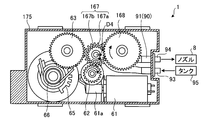
- the drive unit 60 includes a planetary gear 167 and an ejection unit gear 168 in addition to the electric motor 61, the gears 62 and 63, the toothless gear 64, the blade gear 65 and the torsion spring 66 described above. .
- FIGS. 13A and 13B are bottom views when the driving unit 60 accommodated in the case 175 is viewed from the bottom surface side. 13A and 13B show a state in which the lower surface of the case 175 is removed for the convenience of understanding.
- the jet gear 168 is connected to the above-described roller 92 (not visible in FIG. 13A). Further, the jet gear 168 rotates when the driving force of the electric motor 61 is transmitted to rotate the roller 92, that is, drives the cleaning liquid jet 90.
- the planetary gear 167 includes a first gear 167a and a second gear 167b, and is disposed, for example, in a region surrounded by the gear 62, the gear 63, and the ejection portion gear 168.
- the planetary gear 167 is movable between a position where the second gear 167b meshes with the gear 63 (see FIG. 13A) and a position where the second gear 167b meshes with the ejection portion gear 168 (see FIG. 13B). Configured.
- the planetary gear 167 transmits the driving force from the electric motor 61 to the blade portion 40, and the cleaning fluid ejection portion transmission path that transmits the driving force from the electric motor 61 to the cleaning fluid ejection portion 90. Switch.
- the switching of the driving force transmission path by the planetary gear 167 will be described in detail below.
- the first gear 167a is engaged with the gear 62 to which the driving force of the electric motor 61 is transmitted.
- the first gear 167a is arranged coaxially with the second gear 167b and is configured to be integrated with the second gear 167b.
- the electric motor 61 is set so that the rotation direction can be reversed from normal rotation to reverse rotation and from reverse rotation to normal rotation.
- the rotation direction of the electric motor 61 that rotates the gear 62 counterclockwise on the paper surface is the “forward rotation direction”, and conversely, as shown in FIG.
- the direction of rotation that rotates around is called the “reverse direction”.
- the planetary gear 167 moves to a position where the second gear 167b meshes with the gear 63, and transmits the driving force of the electric motor 61 to the gear 63.
- the gear 63 to which the driving force has been transmitted drives the air compression unit 10 via the toothless gear 64 and the blade gear 65, and jets compressed air to the camera 100.
- the planetary gear 167 moves to a position where the second gear 167b meshes with the ejection portion gear 168, and transmits the driving force of the electric motor 61 to the ejection portion gear 168.
- the ejection unit gear 168 to which the driving force is transmitted rotates the roller 92 to eject the cleaning liquid to the camera 100.
- the cleaning liquid ejecting portion 90 is further provided, the deposit on the camera 100 can be efficiently removed with the cleaning liquid.
- the driving unit 60 drives both the blade unit 40 and the cleaning liquid ejection unit 90 of the air compression unit 10.
- the drive part 60 it becomes possible to make the electric motor 61 which is a drive source into one, Therefore Compared with the structure which equips each with the drive source for blade
- the drive unit 60 includes the planetary gear 167 configured as described above.
- the deposit removal apparatus 1 for example, the operation of causing the camera 100 to eject compressed air with a simple configuration in which the rotation of the electric motor 61 is switched between the normal rotation direction and the reverse rotation direction.
- the operation of ejecting the cleaning liquid can be switched.
- the remaining effects are the same as in the previous embodiment.
- FIGS. 14A to 14C are top views when the driving unit 60 accommodated in the case 275 is viewed from the top surface side.
- the drive unit 60 in the fourth embodiment includes the electric motor 61, the gears 62 and 63, the toothless gear 64, the blade gear 65 (not visible in FIG. 14A), and the torsion spring 66 (not visible in FIG. 14A).
- gears 267, 268, 269 and a second partial gear 270 are provided.
- the gear 267 is meshed with the gear 62 and the gear 63.
- the gear 268 is meshed with the toothless gear 64 and the gear 269.
- FIG. 15 is an enlarged perspective view showing the gear 269.
- the gear 269 is arranged coaxially with the second segmented gear 270 and is configured to be integrated with the second segmented gear 270. Therefore, when the gear 269 is rotated, the second partial gear 270 is also rotated in the same direction.
- the second partial gear 270 includes an engagement portion 270a and a partial tooth portion 270b.
- the meshing portion 270a is a portion that can mesh with the ejection portion gear 168.
- the missing tooth portion 270b is a portion that does not mesh with the ejection portion gear 168.
- the electric motor 61 is set to rotate only in the same direction. Therefore, when the driving force of the electric motor 61 is transmitted to the blade gear 65 via the gear 62, the gear 267, the gear 63, and the toothless gear 64, the air compressor 10 is driven and the compressed air is transferred to the camera 100. To erupt.
- the driving force transmitted to the toothless gear 64 is transmitted to the second toothless gear 270 via the gear 268 and the gear 269.
- 14A to 14C for convenience of understanding, the position where the ejection portion gear 168 meshes with the meshing portion 270a of the second partial gear 270 is indicated by a closed closed curve G.
- the roller 92 does not rotate, so that the cleaning liquid is ejected to the camera 100. Not (see FIG. 14C). In this way, the cleaning liquid ejection unit 90 is intermittently driven by the second partial gear 270.
- the cleaning liquid is 1 It is possible to set the operation such as erupting. Therefore, in the deposit removing apparatus 1, the deposit can be effectively removed by appropriately setting the ejection timing of the compressed air and the cleaning liquid according to the environment in which the camera 100 is installed.
- the drive unit 60 in the fourth embodiment is provided with the second partial gear 270 configured as described above.
- the drive unit 60 in the fourth embodiment although it is a simple structure using the electric motor 61 set to the rotation direction rotating only in the same direction, both the air compression part 10 and the washing
- the remaining effects are the same as in the previous embodiment.
- the number of blade portions 40 and the number of cylinder chambers 21 partitioned by the wall portion 30 are specifically shown, but this is merely an example and is not limited.
- the deposit removal apparatus 1 to the camera 100 for vehicles was shown above, it is not restricted to this, For example, other monitoring / security cameras etc. installed in the inside and outside of a building, an alley, etc. You may apply to a camera (optical sensor) of a kind.
Landscapes
- Engineering & Computer Science (AREA)
- Mechanical Engineering (AREA)
- Physics & Mathematics (AREA)
- Optics & Photonics (AREA)
- General Physics & Mathematics (AREA)
- Signal Processing (AREA)
- Multimedia (AREA)
- Automation & Control Theory (AREA)
- Water Supply & Treatment (AREA)
- Studio Devices (AREA)
- Cleaning In General (AREA)
- Camera Bodies And Camera Details Or Accessories (AREA)
- Accessories Of Cameras (AREA)
Abstract
付着物除去装置(1)の省スペース化を図ることを課題とする。かかる課題を解決するために、実施形態の一態様は、カメラ(100)に付着した付着物を除去する付着物除去装置(1)であって、空気圧縮部(10)を備える。空気圧縮部(10)は、シリンダ(20)とシリンダ(20)内に回転軸(C)を中心に回転可能に設けられる羽根部(40)とを有し、羽根部(40)の回転によって生成された圧縮空気をカメラ(100)へ噴出する。
Description
開示の実施形態は、付着物除去装置に関する。
従来、車両に搭載され、車両の周辺の映像を撮像するカメラが知られており、かかるカメラによって撮像された映像は例えば運転者へ提供される。
上記したカメラのレンズには、例えば降雨や降雪等、天候の影響によって水滴や雪、汚れなどの付着物が付着することがある。そこで、付着物を除去するため、カメラのレンズに対して圧縮空気などを噴出するようにした付着物除去装置が提案されている(例えば、特許文献1参照)。
しかしながら、付着物除去装置において、例えばピストンをシリンダ内で往復運動させて圧縮空気を生成する構造である場合、装置の占有スペースが大きくなるおそれがあった。
すなわち、上記したピストン構造の場合、シリンダ内に空気を吸入する際、ピストンと連動するシャフト部分がシリンダの外形から突出することとなるため、かかるシャフト部分の作動領域をシリンダ周辺に確保する必要がある。そのため、上記した付着物除去装置にあっては、シャフト部分の作動領域の分だけ占有スペースが大きくなるおそれがあり、省スペース化を図るという点でさらなる改善の余地があった。
実施形態の一態様は、上記に鑑みてなされたものであって、省スペース化を図ることができる付着物除去装置を提供することを目的とする。
実施形態の一態様は、光学センサに付着した付着物を除去する付着物除去装置であって、空気圧縮部を備える。空気圧縮部は、シリンダと前記シリンダ内に回転軸を中心に回転可能に設けられる回転体とを有し、前記回転体の回転によって生成された圧縮空気を前記光学センサへ噴出する。
実施形態の一態様によれば、付着物除去装置において、省スペース化を図ることができる。
以下、添付図面を参照して、本願の開示する付着物除去装置の実施形態を詳細に説明する。なお、以下に示す実施形態によりこの発明が限定されるものではない。また、以下では、付着物除去装置が、車両の後部に配置され、車両の後方を撮像するカメラに付着した付着物を除去する装置である場合を例にとって説明を行う。
また、以下では、本実施形態に係る付着物除去装置の構成の概要について図1A,1Bを用いて説明した後に、本実施形態に係る付着物除去装置の具体的な構成について、図2以降を用いて説明することとする。
(第1の実施形態)
まず、第1の実施形態に係る付着物除去装置1の構成の概要について図1A,1Bを参照して説明する。
まず、第1の実施形態に係る付着物除去装置1の構成の概要について図1A,1Bを参照して説明する。
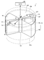
図1Aは、付着物除去装置1の構成の概要を示す一部透視斜視図である。図1Bは、図1AのI-I線断面図であり、付着物除去装置1の動作を説明するための図である。なお、図1Bにおいて付着物除去装置1は、左上図を初期状態とした場合、左上図、右上図、左下図、右下図の順番で動作するものとする。また、図1A,1Bおよび図2以降に示す図は、いずれも模式図である。
図1Aに示すように、付着物除去装置1は空気圧縮部10を備える。かかる空気圧縮部10は、空気を圧縮して圧縮空気を生成し、生成された圧縮空気を車両用のカメラ100へ噴出することで、例えばカメラ100のレンズに付着した水滴等の付着物を除去する。
なお、図1A,1Bを含む各図においては、圧縮空気の流れを破線矢印で示し、後述する吸気の流れを一点鎖線矢印で示すようにした。
ところで、従来の付着物除去装置においては、ピストンをシリンダ内で往復運動させて圧縮空気を生成する構造であったため、装置の占有スペースが大きくなるおそれがあった。すなわち、ピストン構造の場合、ピストンと連動するシャフト部分がシリンダの外形から突出することとなるため、かかるシャフト部分の作動領域をシリンダ周辺に確保する必要があり、その分だけ占有スペースが大きくなるおそれがあった。また、ピストン構造の場合、空気圧縮時のピストンの作動音が比較的大きくなることもあった。
そこで、本実施形態に係る付着物除去装置1にあっては、省スペース化や作動音の低減化を図ることができるような構成とした。以下、かかる付着物除去装置1の構成について詳しく説明する。
本実施形態に係る空気圧縮部10は、回転式の圧縮機構である。具体的には、空気圧縮部10は、図1Aに示すように、シリンダ20と、壁部30と、羽根部40と、流路部50とを備える。なお、図1Aにおいては、理解の便宜のため、シリンダ20を二点鎖線で示し、シリンダ20の内部を透視して示した。
シリンダ20は、例えば円筒状に形成され、内部にシリンダ室21が形成される。かかるシリンダ室21には、上記した壁部30や羽根部40、流路部50などが設けられる。
壁部30は、例えば平板状に形成され、シリンダ20内に立設されて固定される。詳しくは、図1Bの左上図に示すように、壁部30は、円筒状のシリンダ室21を径方向に沿って仕切るように形成される。従って、シリンダ室21は、壁部30によって2つのシリンダ室21に区画されることとなる。
羽根部40は、シリンダ20内に回転軸Cを中心に回転可能に設けられる。羽根部40の回転軸Cは、例えば円筒状のシリンダ室21の中心軸と同軸とされるが、これに限定されるものではない。なお、羽根部40は、回転体の一例である。
羽根部40は、例えば回転軸方向視において扇状に形成される。また、羽根部40は、図1Bの左上図の初期状態にあるとき、言い換えると回転前の状態にあるとき、壁部30の壁面31と対向する側面41を有する形状とされる。なお、羽根部40は、上記した形状に限定されるものではなく、例えば壁部30と同様な平板状などその他の形状であってもよい。
羽根部40は、上記のように2つに区画されたシリンダ室21に1個ずつ収容される。従って、羽根部40は複数個(図示の例では2個)あることとなるが、羽根部40の個数は、壁部30によって区画されるシリンダ室21の数に応じて適宜に変更可能である。
また、2個の羽根部40は、回転軸Cに沿う方向から見た場合に回転対称となるように配置される。なお、ここでは、羽根部40が2個であることから、n回対称(n=2)、すなわち点対称とされるが、羽根部40の個数に応じてnを3以上の整数に変更してもよい。
流路部50は、内部に圧縮空気が流れるように構成される。具体的には、図1Aに示すように、流路部50は、例えば内部が中空の円筒状であるとともに、シリンダ20内に羽根部40の回転軸Cに沿って形成される。
また、流路部50は、圧縮空気が流入する流入口52aと、圧縮空気が流出する流出口52bとを備える。流入口52aは、シリンダ20の底面20a側に形成される。他方、流出口52bは、シリンダ20の天井面20b側に形成される。このため、空気圧縮部10にあっては、圧縮空気を羽根部40の回転軸C方向へ噴出することとなる。
なお、空気圧縮部10は、後述するように、羽根部40の回転によって側面41と壁部30の壁面31との間の空間22(図1B右上図参照)を膨張させて吸気する。かかる吸気の際、流出口52bは、吸気が流路部50内へ流入する開口として機能し、また、流入口52aは、流路部50の吸気が空間22へ流出する開口として機能するものとする。なお、流路部50は、第1流路部の一例である。
次に、上記のように構成された空気圧縮部10の動作について、図1Bを参照して説明する。まず、初期状態における羽根部40は、図1Bの左上図に示すように、側面41が壁部30の壁面31と近接して対向するように位置されるものとする。
続いて、羽根部40は、後述する駆動部60(図5参照)によって回転軸Cを中心に一方方向へ回転される。なお、ここでは、上記した一方方向を、矢印D1で示すように図1Bの紙面において右回り(時計回り)とするが、これに限定されるものではない。
羽根部40の回転により、羽根部40の側面41は、図1Bの右上図に示すように、壁部30の壁面31に対して離間する方向へ移動し、よって空間22が膨張する。これにより、空間22には負圧が生じ、一点鎖線矢印で示すように流路部50から吸気が流入する。
続いて、羽根部40は、図1Bの左下図に示すように、駆動部60(図5参照)によって回転軸Cを中心に他方方向へ回転される。この他方方向は、上記した一方方向とは反対の方向を意味する。ここでは、他方方向は、矢印D2で示すように図1Bの紙面において左回り(反時計回り)とするが、これに限定されるものではない。なお、駆動部60において、羽根部40を一方方向または他方方向へ回転させる構成については、図5,6Aなどを用いて後述する。
羽根部40の他方方向への回転により、羽根部40の側面41は壁部30の壁面31に対して近づく方向へ移動し、よって空間22が圧縮される、すなわち、圧縮空気が生成される。
圧縮空気は、破線矢印で示すように、空間22から流入口52aを介して流路部50へ流入する。なお、羽根部40は、図1Bの右下図に示すように、駆動部60によって他方方向へさらに回転され、側面41が壁部30の壁面31と対向する初期状態の位置まで戻るものとする。
流路部50を流れる圧縮空気は、図1Aに示すように、流出口52bからカメラ100へ向けて噴出される。これにより、例えばカメラ100のレンズに付着した水滴等の付着物を除去することができる。
このように、空気圧縮部10は、羽根部40の回転によって生成された圧縮空気をカメラ100へ噴出するように構成されるため、ピストン構造のようにシリンダの外形からストローク方向に突出する部分がなくなり、空気圧縮部10を小型化することができる。これにより、付着物除去装置1の省スペース化を図ることができる、言い換えると、付着物除去装置1を車両に設置する際の占有スペースを小さくすることができる。
また、回転運動する羽根部40の空気圧縮時の作動音は、往復運動するピストンの空気圧縮時の作動音に比べて小さいことから、付着物除去装置1の空気圧縮部10における作動音を低減させることができる。
また、空気圧縮部10にあっては、羽根部40を回転させるという簡易な構成で圧縮空気を生成することができる。
また、空気圧縮部10にあっては、圧縮空気を羽根部40の回転軸C方向へ噴出する、換言すれば、羽根部40の回転方向に対して直交する方向へ噴出するようにした。これにより、生成された圧縮空気を集約することも可能となり、集約されて比較的高圧となった圧縮空気をカメラ100へ噴出させることができる。
また、流路部50は、シリンダ20内に羽根部40の回転軸Cに沿って形成されるようにした。これにより、生成された圧縮空気を流路部50の1箇所に集約することができ、比較的高圧の圧縮空気を確実に得てカメラ100へ噴出させることができる。
さらには、シリンダ20内においてデッドスペースとなり易い羽根部40の回転軸C付近を、圧縮空気の流路として有効に利用でき、結果として空気圧縮部10を小型化することができる。
また、流路部50は、シリンダ20の底面20a側に形成される流入口52aと、シリンダ20の天井面20b側に形成される流出口52bとを備えた。これにより、流路部50においては、比較的高圧の圧縮空気を得るために必要な流路長さを確保することが可能になる。
また、複数の羽根部40は、回転対称となるように配置されるようにした。これにより、例えば圧縮空気を生成する際に羽根部40が壁部30へ与える衝撃力は、互いに打ち消し合う方向に作用することとなる。そのため、衝撃力による空気圧縮部10への影響を緩和することができる。
以下、図1A,1Bに示した本実施形態に係る付着物除去装置1の構成について、より具体的に説明してゆく。図2は、付着物除去装置1が搭載される車両2を示す斜視図である。
なお、ここでは、付着物除去装置1によって付着物が除去される対象を車両2の後方撮像用のカメラ(リアカメラ)100とするが、これに限定されるものではない。
すなわち、例えばレンズを介して映像を取得したり、車両周辺の物標の情報などを取得したりする光学センサであればよい。具体的には、例えば車両前方を撮像するフロントカメラや車両側方を撮像するサイドカメラ、車両周辺の物標を検出するレーダ装置など種々の光学センサを対象とすることができる。
図2に示すように、付着物除去装置1およびカメラ100は、例えば車両2後部のライセンスプレート3の上部であり、かつ、車両2の左右方向の略中央である位置に設置される。
図3Aは、図2に示す車両2の後部のカメラ100付近を拡大して示す斜視図である。また、図3Bは、図3Aに示すカメラ100をレンズ101側から正面視したときの図である。
図3Aに示すように、車両用バックパネル4にガーニッシュ5が取り付けられ、車両用バックパネル4とガーニッシュ5との間の空間に、カメラ100が配置される。また、ガーニッシュ5には開口5aが設けられており、カメラ100は、かかる開口5aからレンズ101部分が外方へ露出するように配置される。
また、付着物除去装置1は、空気圧縮部10に加え、空気圧縮部10で生成された圧縮空気が流れるホース7およびノズル8を備える。空気圧縮部10は、車両用バックパネル4の背面に設置されているものとする。なお、図3Aにおいては、図示の簡略化のため、空気圧縮部10を四角いブロックで示した。
そして、空気圧縮部10で生成された圧縮空気は、ホース7を介してノズル8からカメラ100のレンズ101へ向けて噴出される(図3Bの破線矢印A参照)。
ここで、カメラ100のレンズ101に対するノズル8の配置位置について説明する。図3Bに示すように、レンズ101の正面視において、ノズル8は、レンズ101の斜め上方に配置される。詳しくは、ノズル8は、破線矢印Aで示される圧縮空気の噴出方向がレンズ101の斜め上方からレンズ101の中心点101aへ向くように配置される。
これにより、レンズ101に対してノズル8を適切に配置することができる。すなわち、仮にノズル8がレンズ101の正面視においてレンズ101の上方に配置されると、ノズル8に付着した水滴などが垂れ下がってカメラ100に映りこんでしまう事象が生じ得る。また、仮にノズル8がレンズ101の正面視においてレンズ101の側方に配置されると、レンズ101が広角レンズであった場合、ノズル8自体がカメラ100に映りこんでしまう事象が生じ得る。そこで、本実施形態では、ノズル8を上記した位置に配置することで、上記した事象の発生を回避して適切に配置することができる。
次に、付着物除去装置1において、圧縮空気を噴出するタイミングの一例について図4を参照して説明しておく。図4は、付着物除去装置1やカメラ100などの構成例を示すブロック図である。
図4に示すように、付着物除去装置1は、上記した空気圧縮部10および駆動部60の他に、制御部70を備える。駆動部60は、上記したように、空気圧縮部10の羽根部40(図1A等参照)を回転させて圧縮空気を生成し、カメラ100へ噴出させる。
制御部70は、図示しないCPUや記憶部などを備えたマイクロコンピュータであり、駆動部60の動作を制御する。制御部70には、ACC検知部71、シフトセンサ72、作動スイッチ73およびカメラ100が接続される。
ACC検知部71は、ACC(アクセサリ電源)がオンされる場合にACCオンを示す信号を制御部70へ出力する。シフトセンサ72は、シフトレバー(図示せず)のポジションを示す信号を制御部70へ出力する。なお、シフトレバーのポジションとしては、車両2を前進させる「前進ポジション」や車両2を後進させる「後進ポジション」等が挙げられる。
作動スイッチ73は、図示しない車室内の適宜位置に設置され、運転者が付着物除去装置1による付着物の除去を所望する場合に操作される。作動スイッチ73は、運転者によって操作されると、操作された旨を示す信号を制御部70へ出力する。また、カメラ100は、撮像した映像を示す信号を制御部70へ出力する。
上記のように構成された付着物除去装置1において、制御部70は、例えばACC検知部71からACCオンを示す信号が入力された場合に、駆動部60を動作させて圧縮空気をカメラ100へ噴出させる。これにより、例えば停車時にカメラ100に付着した水滴などの付着物を除去することが可能となる。
また、制御部70は、例えばシフトセンサ72から後進ポジションを示す信号が入力された場合に、駆動部60を動作させて圧縮空気をカメラ100へ噴出させる。これにより、例えば後進時におけるカメラ100の視界を良好にすることが可能となる。
また、制御部70は、例えば作動スイッチ73から操作された旨を示す信号が入力された場合に、駆動部60を動作させて圧縮空気をカメラ100へ噴出させる。これにより、運転者自身がカメラ100に付着した付着物を認識した場合など、運転者が所望するタイミングで付着物を除去することが可能となる。
また、制御部70は、例えばカメラ100から入力された映像を示す信号を解析し、カメラ100の付着物の有無を判定する。そして、制御部70は、カメラ100に付着物が付着していると判定した場合、駆動部60を動作させて圧縮空気をカメラ100へ噴出させる。これにより、カメラ100に付着した付着物を早期に除去することが可能となる。
なお、上記において、制御部70は、ACC検知部71、シフトセンサ72、作動スイッチ73およびカメラ100からの信号に基づいて駆動部60を動作させるようにしたが、これはあくまでも例示であって限定されるものではない。すなわち、制御部70は、ACC検知部71、シフトセンサ72、作動スイッチ73およびカメラ100からの信号のうち、1つあるいは複数の信号に基づいて駆動部60を動作させるようにしてもよい。
また、駆動部60を動作させるタイミングは、上記に限られず、例えばワイパーが作動するときや、気温・湿度等がカメラ100に水滴が付着し易い条件を満たすときなど、その他のタイミングであってもよい。
図5は、付着物除去装置1の分解斜視図である。図5に示すように、付着物除去装置1は、上記した空気圧縮部10と、駆動部60と、ケース75と、カバー76とを備える。
ケース75は、空気圧縮部10や駆動部60などを収容する。カバー76は、空気圧縮部10等が収容されたケース75の上面に取り付けられ、粉塵などがケース75内に侵入することを防止する。
また、空気圧縮部10のシリンダ20は、吸気部23と、ホース接続口28とを備える。吸気部23は、シリンダ20の天井面20bに形成されるとともに、シリンダ20の中心部分から径方向に沿って外方へ向けて延設される。
図6Aは、シリンダ20を吸気部23において水平方向に切断したときの横断面図である。図6Aに示すように、吸気部23は、吸気流路24と、吸気弁25とを備える。
吸気流路24は、空気圧縮部10への吸気が流れる長尺状の流路である。具体的には、吸気流路24は、一端がシリンダ20の中心に位置されるとともに、上記した流路部50の流出口52bと連通するように形成される。
一方、吸気流路24の他端は、シリンダ20の外周よりも外側に位置される。そして、吸気流路24の他端側に、吸気弁25が取り付けられる。図6Bは、吸気弁25の構成を説明するための拡大縦断面図である。なお、図6Bでは、シリンダ20の上部にカバー76が配置された状態を示した。
図6Bに示すように、吸気弁25は、例えばシリコンゴムなどの弾性を有する弾性材によって製作されたダイヤフラム弁である。詳しくは、吸気弁25は、例えば環状に形成され、中央付近に中央孔25aが形成される。
吸気流路24の他端側には、丸孔状の吸気流入口26が開口される。吸気流入口26の直径は吸気弁25の直径よりも小さくなるように設定されることから、吸気弁25は吸気流入口26の上に載置されて取り付けられる。
また、吸気流入口26の中央付近には、ボス部26aが形成される。ボス部26aは、吸気弁25が取り付けられた状態のとき、上面視において中央孔25aを塞ぐような形状とされる。
上記のような吸気弁25を設けることで、吸気流路24には、吸気のみが流れ、圧縮空気は流れなくなる。すなわち、空気圧縮部10の吸気時(図1B右上図参照)にシリンダ20の空間22が膨張すると、流路部50と連通している吸気流路24に負圧が生じる。この負圧により、吸気弁25は、矢印E1で示すように、中央孔25a付近が上方へ持ち上げられ、よって中央孔25a付近とボス部26aとの間に隙間が生じる。
これにより、図6Bに一点鎖線矢印で示すように、吸気は、吸気流入口26から吸気弁25の中央孔25aを通って吸気流路24へ流れ込み、その後、流路部50の流出口52b、流入口52aを通って空間22へ流入する。
一方、空気圧縮部10の圧縮時(図1B左下図参照)には、吸気流路24は正圧となるため、吸気弁25には矢印E1とは反対方向の力が作用する。そのため、吸気弁25の中央孔25aは、ボス部26aによって封止されることとなる。これにより、圧縮空気が吸気流路24を流れて吸気弁25から流出することはなく、よって圧縮空気の圧力が低下することを抑制することができる。
図7は、シリンダ20の天井面20b付近を示す拡大縦断面図である。図7に想像線で示すように、ホース接続口28には、上記したホース7が接続される。なお、ホース接続口28に接続されるホース7の端部は、ノズル8が接続される端部とは反対側の端部である。
また、ホース接続口28は、ホース7と流路部50の流出口52bとを連通するように形成される。そして、ホース接続口28と流路部50の流出口52bとの間には、排気弁80が取り付けられる。排気弁80は、上記した吸気弁25と同様な構成であることから、ホース接続口28やホース7には、圧縮空気のみが流れ、吸気は流れない。
具体的に説明すると、排気弁80は、弾性材によって製作され、中央付近に中央孔80aが形成されるダイヤフラム弁である。また、カバー76において、流出口52bに対応する位置には、ホース接続口28が挿通される丸孔状の挿通孔77が穿設される。
挿通孔77は、下端付近において孔の直径が排気弁80の直径よりも小さくなるように形成される部位を備え、かかる部位に排気弁80が載置されて取り付けられる。挿通孔77において排気弁80が載置される部位には、ボス部77aが形成される。ボス部77aは、排気弁80が取り付けられた状態のとき、上面視において中央孔80aを塞ぐような形状とされる。
従って、空気圧縮部10の圧縮時には、流路部50は正圧となるため、排気弁80は、矢印E2で示すように、中央孔80a付近が上方へ持ち上げられ、よって中央孔80a付近とボス部77aとの間に隙間が生じる。
これにより、図7に破線矢印で示すように、圧縮空気は、流路部50の流出口52bから排気弁80の中央孔80a、ホース接続口28、ホース7およびノズル8(図3A参照)を通ってカメラ100へ噴出される。
一方、空気圧縮部10の吸気時(図1B右上図参照)には、流路部50は負圧となるため、排気弁80には矢印E2とは反対方向の力が作用する。そのため、排気弁80の中央孔80aは、ボス部77aによって封止されることとなる。
従って、吸気がノズル8からホース7、ホース接続口28を介して流路部50へ逆流することはない。これにより、例えばノズル8に付着した水滴やゴミなどの異物が、吸気とともに流路部50などへ侵入してしまうことを抑制することができる。
また、仮に圧縮空気の流出口が複数箇所ある場合、排気弁80も複数必要になるが、本実施形態では、流路部50が羽根部40の回転軸Cに沿って形成されるとともに、流出口52bが1箇所であることから、排気弁80を1つにすることができる。
図5の説明に戻ると、複数個(ここでは2個)の羽根部40は、円盤状のベース部42上に設けられる。従って、ベース部42が回転軸C(図1A参照)を中心に回転させられると、2個の羽根部40も同様に回転することとなる。
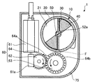
駆動部60は、電動モータ61と、歯車62,63と、欠歯歯車64(図8A参照)と、羽根部用歯車65と、ねじりバネ66とを備える。図8A~8Dは、かかる駆動部60の構成およびその動作を説明するための図である。
なお、図8A~8Dは、駆動部60や空気圧縮部10の上面図であり、理解の便宜のため、部分的に断面にして示した。また、図8A,8B,8C,8Dにおける空気圧縮部10の状態は順に、図1Bの左上図、右上図、左下図、右下図にそれぞれ対応している。
図8Aに示すように、電動モータ61は、空気圧縮部10の羽根部40を駆動させる駆動源の一例である。なお、上記では、電動モータ61を駆動源の例として挙げたが、これに限られず、油圧モータなど他の種類の駆動源であってもよい。
電動モータ61は、出力軸61aを備える。出力軸61aには、例えば図示しないウォームギアが形成され、歯車62と噛合する。また、歯車62は、歯車63にも噛合され、電動モータ61からの駆動力を歯車63へ伝達する。
歯車63は、欠歯歯車64と同軸に配置されるとともに、欠歯歯車64と一体となるように構成される。従って、歯車63が電動モータ61からの駆動力によって回転すると、それに伴って欠歯歯車64も同一方向(図8Aに示す例では反時計周り方向)に回転することとなる。
欠歯歯車64は、噛合部分64aと、欠歯部分64bとを備える。噛合部分64aは、欠歯歯車64の外周において、歯が形成されて羽根部用歯車65と噛合することが可能な部位である。また、欠歯部分64bは、欠歯歯車64の外周において、歯が形成されずに羽根部用歯車65と噛合しない部位である。
なお、欠歯歯車64は、第1欠歯歯車の一例である。また、上記したように、欠歯歯車64は、電動モータ61に歯車63、歯車62を介して接続され、電動モータ61の駆動力が伝達されている。
羽根部用歯車65(図5参照。図8Aではベース部42に隠れて見えず)は、羽根部40に接続される。詳しくは、図5に示すように、羽根部用歯車65は、ベース部42において羽根部40が設けられる面とは反対側の面、すなわち下面に形成される。なお、図8A~8Dにおいては、理解の便宜のため、羽根部用歯車65と欠歯歯車64の噛合部分64aとが噛合する位置を破線の閉曲線Fで示した。
また、羽根部用歯車65は、閉曲線Fの位置において、欠歯歯車64の噛合部分64aと噛合して電動モータ61からの駆動力が伝達されるとき、羽根部40を一方方向(図8Aでは時計周り方向)へ回転させるが、これについては後述する。なお、羽根部用歯車65は、回転体用歯車の一例である。
ねじりバネ66は、例えば周方向に弾性変形可能とされるとともに、一端がケース75に接続する一方、他端が羽根部40に接続するように構成される。そして、ねじりバネ66は、羽根部40を他方方向(図8Aで反時計周り方向)へ回転させるように付勢する。
なお、ねじりバネ66は、付勢部の一例であるが、これは例示であって限定されるものではない。すなわち、付勢部としては、周方向に弾性変形するものであれば、例えば板ばねや渦巻きばねなど他の種類のものであってもよい。
次に、駆動部60の動作について説明する。まず、羽根部40が回転する前の初期状態にあるときは、図8Aに示すように、欠歯歯車64の欠歯部分64bが閉曲線Fの位置において羽根部用歯車65と対向して位置されるものとする。すなわち、羽根部用歯車65は、電動モータ61の駆動力が伝達されていない状態とされる。
続いて、図8Bに示すように、欠歯歯車64が電動モータ61の駆動力によって回転し、噛合部分64aが羽根部用歯車65と閉曲線Fの位置において噛合する。かかる場合、羽根部用歯車65および羽根部40は、電動モータ61の駆動力が伝達されることから、ねじりバネ66の付勢力に抗して一方方向へ回転する。これにより、羽根部40と壁部30と間の空間22が膨張し、吸気が行われる。
続いて、図8Cおよび図8Dに示すように、欠歯歯車64が電動モータ61の駆動力によってさらに回転し、欠歯部分64bが閉曲線Fの位置において羽根部用歯車65と対向した位置とされる。すなわち、羽根部用歯車65は、電動モータ61の駆動力が伝達されていない状態とされる。これにより、羽根部用歯車65および羽根部40は、ねじりバネ66の付勢力によって他方方向へ回転し、よって膨張した空間22が圧縮して圧縮空気が生成される。
このように、駆動部60において、電動モータ61の駆動力を羽根部40へ伝達する伝達経路に、欠歯歯車64を備えるようにした。これにより、付着物除去装置1の駆動部60にあっては、例えば回転方向が同一方向にのみ回転する設定の電動モータ61を用いる簡易な構成でありながら、羽根部40を一方方向から他方方向へ反転させるように駆動させることができる。
上述してきたように、第1の実施形態では、カメラ100に付着した付着物を除去する付着物除去装置1であって、空気圧縮部10を備える。空気圧縮部10は、シリンダ20とシリンダ20内に回転軸Cを中心に回転可能に設けられる羽根部40とを有し、羽根部40の回転によって生成された圧縮空気をカメラ100へ噴出する。これにより、空気圧縮部10のサイズが小型化されるため、付着物除去装置1の省スペース化を図ることができる。
(第2の実施形態)
次いで、第2の実施形態に係る付着物除去装置1について説明する。第1の実施形態では、圧縮空気が流れる流路部50を羽根部40の回転軸Cに沿って形成するようにしたが、第2の実施形態では、圧縮空気をシリンダ20の外周側から天井面20b付近に集約し、天井面20b付近からカメラ100へ噴出する構成とした。
次いで、第2の実施形態に係る付着物除去装置1について説明する。第1の実施形態では、圧縮空気が流れる流路部50を羽根部40の回転軸Cに沿って形成するようにしたが、第2の実施形態では、圧縮空気をシリンダ20の外周側から天井面20b付近に集約し、天井面20b付近からカメラ100へ噴出する構成とした。
図9は、第2の実施形態に係る付着物除去装置1の構成を示す一部透視斜視図である。図10は、図9に示す付着物除去装置1の縦断面図である。また、以下においては、上記した実施形態と共通の構成については、同一の符号を付して説明を省略する。
図9,10に示すように、第2の実施形態における空気圧縮部10のシリンダ20は、流路部150と、連通口121とを備える。なお、第1の実施形態において、流路部50が形成されていた羽根部40の回転軸C付近には、流路部50に代えて、中実に構成された円柱部151が設けられている。
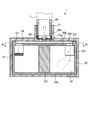
図11は、図10のXI-XI線断面図である。図10,11によく示すように、流路部150は、シリンダ20の天井面20bに形成され、後述するように圧縮空気や吸気が流れるように構成される。
また、流路部150は、回転軸Cに沿う方向から見た場合に、回転軸Cを中心に回転対称(図11の例では点対称)となるような形状に形成される。なお、流路部150は、第2流路部の一例である。
また、図11に示すように、流路部150は、シリンダ20の外周よりも外側に部分的に突出する突出部位150aが形成される。そして、かかる突出部位150aに、吸気弁25が載置されて取り付けられる。従って、空気圧縮部10の吸気時には、突出部位150aの吸気弁25から流路部150へ吸気が流れ込むこととなる。
また、図9に示すように、壁部30は傾斜部131を備える。傾斜部131は、シリンダ20の外周側で、かつ、天井面20b側の位置に形成される。また、傾斜部131は、例えば羽根部40の側面41から離間する方向へ上り勾配となるように傾斜される。
連通口121は、シリンダ20の天井面20bにおいて壁部30付近、詳しくは壁部30においてシリンダ20の外周側に形成された傾斜部131付近に設けられ、シリンダ室21と流路部150とを連通する。
第2の実施形態にあっては、上記のように構成することで、例えば空気圧縮部10の吸気時には、図11に一点鎖線矢印で示すように、吸気は、吸気弁25の中央孔25aから流路部150へ流れ込む。その後、吸気は、連通口121を通って空間22(図1B左下図参照)へ流入することとなる。
一方、空気圧縮部10の圧縮時には、圧縮空気は、シリンダ20の空間22から傾斜部131および連通口121を介して流路部150へ流入することとなる。その後、圧縮空気は、流路部150から排気弁80の中央孔80a、ホース接続口28、ホース7およびノズル8(図3A参照)を通ってカメラ100へ噴出される。
このように、第2の実施形態にあっては、圧縮空気をシリンダ20の外周側から天井面20b付近の流路部150に集約し、流路部150からカメラ100へ噴出するようにした。これにより、第1の実施形態と同様、ピストン構造のようにシリンダの外形からストローク方向に突出する部分がなくなり、空気圧縮部10を小型化でき、付着物除去装置1の省スペース化を図ることができる。なお、残余の効果は、第1の実施形態と同様である。
(第3の実施形態)
次いで、第3の実施形態に係る付着物除去装置1について説明する。第3の実施形態に係る付着物除去装置1にあっては、カメラ100に対し、圧縮空気に加えて、洗浄液を噴出するような構成とした。
次いで、第3の実施形態に係る付着物除去装置1について説明する。第3の実施形態に係る付着物除去装置1にあっては、カメラ100に対し、圧縮空気に加えて、洗浄液を噴出するような構成とした。
以下、第3の実施形態に係る付着物除去装置1の構成について図12を参照して説明する。図12は、第3の実施形態に係る付着物除去装置1の分解斜視図である。
図12に示すように、第3の実施形態に係る付着物除去装置1は、空気圧縮部10に加え、洗浄液噴出部90を備える。洗浄液噴出部90としては、例えばローラポンプを用いることができるが、これに限定されるものではない。
具体的に洗浄液噴出部90は、洗浄液用チューブ91と、ローラ92とを備える。洗浄液用チューブ91は、一端が洗浄液を貯留する接続口93を介してタンク95(図13A参照)に接続される一方、他端が接続口94を介してノズル8(図3A,13A参照)に接続される。なお、洗浄液用チューブ91には、タンク95からの洗浄液が充填されているものとする。
ローラ92には、洗浄液用チューブ91が巻き付くように取り付けられる。また、ローラ92は、後述する噴出部用歯車168に接続され、噴出部用歯車168によって回転させられるとき、洗浄液用チューブ91を押しつぶす。
そして、洗浄液噴出部90は、ローラ92によって押しつぶされた洗浄液用チューブ91が元に戻るときの圧力を利用して、洗浄液をノズル8へ圧送し、カメラ100へ噴出する。なお、洗浄液を噴出するノズル8は、圧縮空気を噴出するノズル8と共用であっても、別々であってもよい。
第3の実施形態における駆動部60は、上記した電動モータ61、歯車62,63、欠歯歯車64、羽根部用歯車65およびねじりバネ66に加え、遊星歯車167および噴出部用歯車168を備える。
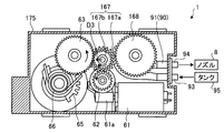
次に、駆動部60の遊星歯車167や噴出部用歯車168の構成、および駆動部60の動作について図13A,13Bを参照して説明する。図13A,13Bは、ケース175に収容された駆動部60を下面側から見た場合の下面図である。なお、図13A,13Bにあっては、理解の便宜のため、ケース175の下面を取り除いた状態を示している。
噴出部用歯車168は、上記したローラ92(図13Aで見えず)に接続される。また、噴出部用歯車168は、電動モータ61の駆動力が伝達されるときに回転駆動してローラ92を回転させる、すなわち、洗浄液噴出部90を駆動させる。
遊星歯車167は、第1歯車167aと、第2歯車167bとを備え、例えば歯車62と、歯車63と、噴出部用歯車168とによって囲まれる領域に配置される。
遊星歯車167は、かかる領域において、第2歯車167bが歯車63に噛合する位置(図13A参照)と、噴出部用歯車168に噛合する位置(図13B参照)との間で移動自在となるように構成される。
この移動により、遊星歯車167は、電動モータ61から羽根部40へ駆動力を伝達する回転体用伝達経路と、電動モータ61から洗浄液噴出部90へ駆動力を伝達する洗浄液噴出部用伝達経路とを切り替える。
遊星歯車167による駆動力の伝達経路の切り替えについて、以下詳しく説明すると、第1歯車167aは、電動モータ61の駆動力が伝達される歯車62に噛合される。また、第1歯車167aは、第2歯車167bと同軸に配置されるとともに、第2歯車167bと一体となるように構成される。
ここで、電動モータ61は、回転方向を正転から逆転、逆転から正転へと反転させることができるように設定される。以下では、図13Aに示すように、歯車62を紙面において反時計回りに回転させるような電動モータ61の回転方向を「正転方向」、逆に、図13Bに示すように、歯車62を時計回りに回転させるような回転方向を「逆転方向」ということとする。
図13Aに示すように、電動モータ61が正転方向に回転する場合、歯車62は反時計回りに回転する。歯車62と噛合する遊星歯車167の第1歯車167aは、歯車62から駆動力が伝達されて時計周りに回転する。このとき、第1歯車167aには、歯車63方向へ移動させる向き(矢印D3参照)の力も作用する。
これにより、遊星歯車167は、第2歯車167bが歯車63に噛合する位置に移動し、電動モータ61の駆動力を歯車63へ伝達する。駆動力が伝達された歯車63は、欠歯歯車64、羽根部用歯車65を介して空気圧縮部10を駆動し、圧縮空気をカメラ100へ噴出させる。
他方、図13Bに示すように、電動モータ61が逆転方向に回転する場合、歯車62は時計回りに回転する。歯車62と噛合する遊星歯車167の第1歯車167aは、歯車62から駆動力が伝達されて反時計周りに回転する。このとき、第1歯車167aには、噴出部用歯車168へ移動させる向き(矢印D4参照)の力も作用する。
これにより、遊星歯車167は、第2歯車167bが噴出部用歯車168に噛合する位置に移動し、電動モータ61の駆動力を噴出部用歯車168へ伝達する。駆動力が伝達された噴出部用歯車168は、ローラ92を回転駆動し、洗浄液をカメラ100へ噴出させる。
このように、第3の実施形態にあっては、洗浄液噴出部90をさらに備えるようにしたので、カメラ100の付着物を洗浄液によって効率よく除去することができる。
また、第3の実施形態では、駆動部60が空気圧縮部10の羽根部40および洗浄液噴出部90の両方を駆動させるようにした。これにより、駆動部60においては、駆動源である電動モータ61を1つにすることが可能となり、よって羽根部40用および洗浄液噴出部90用の駆動源をそれぞれ備えるような構成に比べて、付着物除去装置1をさらに省スペース化することができる。
また、第3の実施形態では、駆動部60が、上記のように構成された遊星歯車167を備えるようにした。これにより、付着物除去装置1にあっては、例えば、電動モータ61の回転を正転方向と逆転方向との間で切り替えるという簡易な構成で、カメラ100に対して圧縮空気を噴出させる動作と洗浄液を噴出させる動作とを切り替えることができる。なお、残余の効果は、従前の実施形態と同様である。
(第4の実施形態)
次いで、第4の実施形態に係る付着物除去装置1について説明する。第4の実施形態にあっては、圧縮空気を噴出させる動作と洗浄液を噴出させる動作との切り替えを、駆動部60に用いる歯車を工夫することで行うようにした。
次いで、第4の実施形態に係る付着物除去装置1について説明する。第4の実施形態にあっては、圧縮空気を噴出させる動作と洗浄液を噴出させる動作との切り替えを、駆動部60に用いる歯車を工夫することで行うようにした。
以下、第4の実施形態に係る駆動部60の構成、および駆動部60の動作について図14A~14Cを参照して説明する。図14A~14Cは、ケース275に収容された駆動部60を上面側から見た場合の上面図である。
第4の実施形態における駆動部60は、上記した電動モータ61、歯車62,63、欠歯歯車64、羽根部用歯車65(図14Aで見えず)、ねじりバネ66(図14Aで見えず)、噴出部用歯車168に加え、歯車267,268,269および第2欠歯歯車270を備える。
図14Aに示すように、歯車267は、歯車62と歯車63とに噛合される。歯車268は、欠歯歯車64と歯車269とに噛合される。
図15は、歯車269を拡大して示す斜視図である。図14A,15に示すように、歯車269は、第2欠歯歯車270と同軸に配置されるとともに、第2欠歯歯車270と一体となるように構成される。従って、歯車269が回転すると、それに伴って第2欠歯歯車270も同一方向に回転することとなる。
第2欠歯歯車270は、噛合部分270aと、欠歯部分270bとを備える。噛合部分270aは、噴出部用歯車168と噛合することが可能な部位である。また、欠歯部分270bは、噴出部用歯車168と噛合しない部位である。
ここで、電動モータ61は、回転方向が同一方向にのみ回転する設定であるものとする。従って、電動モータ61の駆動力が、歯車62、歯車267、歯車63、欠歯歯車64を介して羽根部用歯車65に伝達されるとき、空気圧縮部10が駆動し、圧縮空気をカメラ100へ噴出させる。
また、欠歯歯車64に伝達された駆動力が、歯車268、歯車269を介して第2欠歯歯車270に伝達される。なお、図14A~14Cにおいては、理解の便宜のため、噴出部用歯車168と第2欠歯歯車270の噛合部分270aとが噛合する位置を破線の閉曲線Gで示した。
伝達された駆動力によって第2欠歯歯車270が回転し、噛合部分270aが閉曲線Gの位置において噴出部用歯車168と噛合する位置にあるとき、噴出部用歯車168は、ローラ92を回転駆動し、洗浄液をカメラ100へ噴出させる(図14B参照)。
また、伝達された駆動力によって第2欠歯歯車270が回転し、欠歯部分270bが噴出部用歯車168と対向した位置にあるとき、ローラ92は回転しないことから、洗浄液はカメラ100へ噴出されない(図14C参照)。このように、洗浄液噴出部90は、第2欠歯歯車270によって間欠的に駆動される。
従って、欠歯歯車64や第2欠歯歯車270において、噛合部分64a,270aの歯数や外周面における長さなどを変更することで、例えば圧縮空気を3回噴出させた後、洗浄液を1回噴出させるなど動作を設定することができる。従って、付着物除去装置1にあっては、カメラ100が設置される環境に応じて、圧縮空気および洗浄液の噴出タイミングを適切に設定することで、付着物を効果的に除去することができる。
また、第4の実施形態における駆動部60にあっては、上記のように構成された第2欠歯歯車270を備えるようにした。これにより、第4の実施形態においては、回転方向が同一方向にのみ回転する設定の電動モータ61を用いる簡易な構成でありながら、空気圧縮部10および洗浄液噴出部90の両方を駆動することができる。なお、残余の効果は、従前の実施形態と同様である。
なお、上述した実施形態では、羽根部40の個数や壁部30によって仕切られるシリンダ室21の数を具体的に示したが、これはあくまでも例示であって限定されるものではない。
また、上記では、付着物除去装置1を車両用のカメラ100に適用する例を示したが、これに限られず、例えば、建物の内外や路地等に設置される監視/防犯カメラなどのその他の種類のカメラ(光学センサ)に適用してもよい。
さらなる効果や変形例は、当業者によって容易に導き出すことができる。このため、本発明のより広範な態様は、以上のように表しかつ記述した特定の詳細および代表的な実施形態に限定されるものではない。したがって、添付の請求の範囲およびその均等物によって定義される総括的な発明の概念の精神または範囲から逸脱することなく、様々な変更が可能である。
1 付着物除去装置
10 空気圧縮部
20 シリンダ
30 壁部
40 羽根部
50 流路部
60 駆動部
61 電動モータ
64 欠歯歯車
65 羽根部用歯車
66 ねじりバネ
90 洗浄液噴出部
121 連通口
167 遊星歯車
270 第2欠歯歯車
10 空気圧縮部
20 シリンダ
30 壁部
40 羽根部
50 流路部
60 駆動部
61 電動モータ
64 欠歯歯車
65 羽根部用歯車
66 ねじりバネ
90 洗浄液噴出部
121 連通口
167 遊星歯車
270 第2欠歯歯車
Claims (10)
- 光学センサに付着した付着物を除去する付着物除去装置であって、
シリンダと前記シリンダ内に回転軸を中心に回転可能に設けられる回転体とを有し、前記回転体の回転によって生成された圧縮空気を前記光学センサへ噴出する空気圧縮部
を備えることを特徴とする付着物除去装置。 - 前記空気圧縮部は、
前記圧縮空気を前記回転体の回転軸方向へ噴出すること
を特徴とする請求項1に記載の付着物除去装置。 - 前記空気圧縮部は、
前記シリンダ内に前記回転体の回転軸に沿って形成され前記圧縮空気が流れる第1流路部
を備えることを特徴とする請求項1または2に記載の付着物除去装置。 - 前記第1流路部は、
前記シリンダの底面側に形成され前記圧縮空気が流入する流入口と、
前記シリンダの天井面側に形成され前記圧縮空気が流出する流出口と
を備えることを特徴とする請求項3に記載の付着物除去装置。 - 前記シリンダは、
円筒状に形成され前記回転体を収容するシリンダ室と、
前記シリンダ室を径方向に沿って仕切るように形成される壁部と、
前記シリンダの天井面に形成され前記圧縮空気が流れる第2流路部と、
前記シリンダの天井面において前記壁部付近に設けられ、前記シリンダ室と前記第2流路部とを連通する連通口と
を備え、前記シリンダ室内で生成された前記圧縮空気が、前記連通口を介して前記第2流路部へ流入し、前記第2流路部から前記光学センサへ噴出すること
を特徴とする請求項1または2に記載の付着物除去装置。 - 前記回転体を回転駆動させる駆動部
をさらに備え、
前記駆動部は、
駆動源と、
前記回転体に接続されるとともに、前記駆動源から駆動力が伝達されるときに前記回転体を一方方向へ回転させる回転体用歯車と、
前記回転体を他方方向へ回転させるように付勢する付勢部と、
前記回転体用歯車と噛合することが可能な噛合部分と、前記回転体用歯車と噛合しない欠歯部分とを有するとともに、前記駆動源に接続される第1欠歯歯車と
を備え、
前記回転体は、
前記第1欠歯歯車の噛合部分が前記回転体用歯車と噛合する位置にあるとき、前記付勢部の付勢力に抗して前記一方方向へ回転して前記回転体と前記シリンダ内の壁部との間の空間を膨張させ、前記第1欠歯歯車の欠歯部分が前記回転体用歯車と対向した位置にあるとき、前記付勢部の付勢力によって前記他方方向へ回転して前記膨張した空間を圧縮すること
を特徴とする請求項1または2に記載の付着物除去装置。 - 前記回転体は複数個あり、
複数個の前記回転体は、
前記回転軸に沿う方向から見た場合に回転対称となるように配置されること
を特徴とする請求項1または2に記載の付着物除去装置。 - 洗浄液を前記光学センサへ噴出する洗浄液噴出部と、
前記回転体および前記洗浄液噴出部の両方を駆動させる駆動部と
を備えることを特徴とする請求項1または2に記載の付着物除去装置。 - 前記駆動部は、
駆動源と、
前記駆動源から前記回転体へ駆動力を伝達する回転体用伝達経路と前記駆動源から前記洗浄液噴出部へ駆動力を伝達する洗浄液噴出部用伝達経路とを切り替える遊星歯車と
を備えることを特徴とする請求項8に記載の付着物除去装置。 - 前記駆動部は、
駆動源と、
前記洗浄液噴出部に接続されるとともに、前記駆動源の駆動力が伝達されるときに回転して前記洗浄液噴出部を駆動させる噴出部用歯車と、
前記噴出部用歯車と噛合することが可能な噛合部分と、前記噴出部用歯車と噛合しない欠歯部分とを有するとともに、前記駆動源の駆動力によって回転する第2欠歯歯車と
を備え、
前記洗浄液噴出部は、
前記第2欠歯歯車の噛合部分が前記噴出部用歯車と噛合する位置にあるとき、前記洗浄液を前記光学センサへ噴出し、前記第2欠歯歯車の欠歯部分が前記噴出部用歯車と対向した位置にあるとき、前記洗浄液を前記光学センサへ噴出しないこと
を特徴とする請求項8に記載の付着物除去装置。
Priority Applications (3)
| Application Number | Priority Date | Filing Date | Title |
|---|---|---|---|
| DE112016001913.0T DE112016001913B4 (de) | 2015-12-28 | 2016-09-23 | Fremdmaterial-Beseitigungsgerät |
| CN201680032561.7A CN107848496B (zh) | 2015-12-28 | 2016-09-23 | 附着物除去装置 |
| US15/557,363 US10459219B2 (en) | 2015-12-28 | 2016-09-23 | Extraneous-matter removing apparatus |
Applications Claiming Priority (2)
| Application Number | Priority Date | Filing Date | Title |
|---|---|---|---|
| JP2015256975A JP6654430B2 (ja) | 2015-12-28 | 2015-12-28 | 噴射装置および噴射システム |
| JP2015-256975 | 2015-12-28 |
Publications (1)
| Publication Number | Publication Date |
|---|---|
| WO2017115506A1 true WO2017115506A1 (ja) | 2017-07-06 |
Family
ID=59225689
Family Applications (1)
| Application Number | Title | Priority Date | Filing Date |
|---|---|---|---|
| PCT/JP2016/078018 Ceased WO2017115506A1 (ja) | 2015-12-28 | 2016-09-23 | 付着物除去装置 |
Country Status (5)
| Country | Link |
|---|---|
| US (1) | US10459219B2 (ja) |
| JP (1) | JP6654430B2 (ja) |
| CN (1) | CN107848496B (ja) |
| DE (1) | DE112016001913B4 (ja) |
| WO (1) | WO2017115506A1 (ja) |
Cited By (1)
| Publication number | Priority date | Publication date | Assignee | Title |
|---|---|---|---|---|
| US10782520B2 (en) | 2018-07-24 | 2020-09-22 | Ford Global Technologies, Llc | Cleaning system for vehicle sensor |
Families Citing this family (14)
| Publication number | Priority date | Publication date | Assignee | Title |
|---|---|---|---|---|
| JP6654550B2 (ja) * | 2016-11-22 | 2020-02-26 | 株式会社デンソーテン | 回転装置および付着物除去装置 |
| JP7055619B2 (ja) | 2017-11-14 | 2022-04-18 | 株式会社デンソーテン | 気体噴出装置および気体噴出方法 |
| JP7016674B2 (ja) * | 2017-11-14 | 2022-02-07 | 株式会社デンソーテン | 気体噴出装置および気体噴出方法 |
| JP6986422B2 (ja) * | 2017-11-14 | 2021-12-22 | 株式会社デンソーテン | 気体噴射装置および気体噴射システム |
| JP7319419B2 (ja) * | 2017-11-14 | 2023-08-01 | 株式会社デンソーテン | 気体噴出装置および気体噴出方法 |
| JP7000127B2 (ja) * | 2017-11-14 | 2022-01-19 | 株式会社デンソーテン | 気体噴射装置および気体噴射システム |
| JP6740275B2 (ja) | 2018-04-04 | 2020-08-12 | ファナック株式会社 | 清掃装置 |
| CN110481508A (zh) * | 2018-08-30 | 2019-11-22 | 广州绿口十科技有限责任公司 | 一种无人驾驶汽车摄像头吹风装置及方法 |
| JP7029367B2 (ja) | 2018-08-31 | 2022-03-03 | 株式会社デンソーテン | 圧縮装置 |
| JP7161893B2 (ja) | 2018-08-31 | 2022-10-27 | 株式会社デンソーテン | 圧縮装置 |
| CN109334614B (zh) * | 2018-11-28 | 2023-10-10 | 浙江警察学院 | 一种汽车侧车窗刮雨装置 |
| FR3105745B1 (fr) * | 2019-12-27 | 2022-12-16 | Valeo Systemes Dessuyage | Dispositif de protection d’un organe optique, système d’assistance à la conduite et procédé de nettoyage correspondants |
| US20240280675A1 (en) * | 2023-02-20 | 2024-08-22 | Apple Inc. | Sensor system |
| FR3147762B1 (fr) * | 2023-04-17 | 2025-06-20 | Valeo Systemes Dessuyage | Dispositif de nettoyage d’une surface de détection d’un dispositif de détection |
Citations (8)
| Publication number | Priority date | Publication date | Assignee | Title |
|---|---|---|---|---|
| US4026468A (en) * | 1975-08-14 | 1977-05-31 | Mccord Corporation | Headlamp cleaning assembly |
| JPS6328889U (ja) * | 1986-08-07 | 1988-02-25 | ||
| US5083339A (en) * | 1989-11-01 | 1992-01-28 | Sprague Aristo-Aire, Inc. | Apparatus for cleaning headlight lens and similar surfaces |
| JPH06240519A (ja) * | 1987-01-20 | 1994-08-30 | Tatsumi Eyaa Eng:Kk | 紡機下の繊維屑吹払装置 |
| JP2000233378A (ja) * | 1999-02-16 | 2000-08-29 | Kanto Auto Works Ltd | ワーククランプ具 |
| JP2002195211A (ja) * | 2000-12-18 | 2002-07-10 | Btm Corp | 流体装置及びショットピン装置 |
| JP2007146706A (ja) * | 2005-11-25 | 2007-06-14 | Mitsumi Electric Co Ltd | ポンプ |
| JP2014037239A (ja) * | 2011-10-14 | 2014-02-27 | Denso Corp | カメラ洗浄装置 |
Family Cites Families (18)
| Publication number | Priority date | Publication date | Assignee | Title |
|---|---|---|---|---|
| JPS5336881B2 (ja) * | 1974-05-17 | 1978-10-05 | ||
| JPS61234201A (ja) * | 1985-04-11 | 1986-10-18 | Kishino Masahide | 同心的に回転する回転ピストン変容機械 |
| JP2983274B2 (ja) * | 1990-10-03 | 1999-11-29 | 自動車機器株式会社 | 変速機操作装置 |
| JPH06323103A (ja) * | 1993-05-18 | 1994-11-22 | Kimii Nakatani | 回転伝達機構 |
| KR100189288B1 (ko) | 1996-02-15 | 1999-06-01 | 윤종용 | 기류를 이용한 카메라 하우징의 먼지 제거장치 |
| US7222388B2 (en) * | 2003-04-10 | 2007-05-29 | Canon Kabushiki Kaisha | Imaging-device cleaning apparatus |
| JP2005354330A (ja) * | 2004-06-10 | 2005-12-22 | Pentax Corp | デジタルカメラ及びそのクリーニング装置 |
| JP2011521168A (ja) * | 2008-05-26 | 2011-07-21 | 振明 ▲張▼ | デユアルローターエンジン |
| KR101042302B1 (ko) | 2010-12-27 | 2011-06-17 | 위재영 | 차량 외부 영상 장치용 하우징 |
| JP5494743B2 (ja) * | 2011-10-14 | 2014-05-21 | 株式会社デンソー | カメラ洗浄装置 |
| JP5218930B1 (ja) * | 2012-09-21 | 2013-06-26 | 武史 畑中 | ロータリ内燃機関及びこれにより駆動される車両並びにハイブリッド車両 |
| DE102014204091A1 (de) | 2013-06-18 | 2014-12-18 | Robert Bosch Gmbh | Bearbeitungsmaschine zur autonomen Bearbeitung eines zugeordneten Arbeitsbereichs |
| JP6417757B2 (ja) * | 2013-09-19 | 2018-11-07 | 株式会社デンソー | 車載光学センサ洗浄装置 |
| CN106163888B (zh) | 2014-04-14 | 2019-06-28 | 株式会社小糸制作所 | 异物除去装置 |
| EP2949521B1 (en) * | 2014-05-27 | 2019-07-24 | Fico Transpar, S.A. | Cleaning device and system for vehicle-mounted optic surface and vehicle-mounted optic sensor with cleaning device |
| EP2949520B1 (en) * | 2014-05-27 | 2018-03-21 | Fico Transpar, S.A. | System for cleaning a vehicle-mounted optic lens |
| US10059280B2 (en) * | 2014-06-06 | 2018-08-28 | Joseph Richard Cooper | Obstruction-removal system and method for vehicle-camera lens |
| JP2016008005A (ja) | 2014-06-26 | 2016-01-18 | ダイハツ工業株式会社 | 自動車用バックモニタ装置のカメラレンズ洗浄構造 |
-
2015
- 2015-12-28 JP JP2015256975A patent/JP6654430B2/ja active Active
-
2016
- 2016-09-23 CN CN201680032561.7A patent/CN107848496B/zh active Active
- 2016-09-23 US US15/557,363 patent/US10459219B2/en active Active
- 2016-09-23 DE DE112016001913.0T patent/DE112016001913B4/de active Active
- 2016-09-23 WO PCT/JP2016/078018 patent/WO2017115506A1/ja not_active Ceased
Patent Citations (8)
| Publication number | Priority date | Publication date | Assignee | Title |
|---|---|---|---|---|
| US4026468A (en) * | 1975-08-14 | 1977-05-31 | Mccord Corporation | Headlamp cleaning assembly |
| JPS6328889U (ja) * | 1986-08-07 | 1988-02-25 | ||
| JPH06240519A (ja) * | 1987-01-20 | 1994-08-30 | Tatsumi Eyaa Eng:Kk | 紡機下の繊維屑吹払装置 |
| US5083339A (en) * | 1989-11-01 | 1992-01-28 | Sprague Aristo-Aire, Inc. | Apparatus for cleaning headlight lens and similar surfaces |
| JP2000233378A (ja) * | 1999-02-16 | 2000-08-29 | Kanto Auto Works Ltd | ワーククランプ具 |
| JP2002195211A (ja) * | 2000-12-18 | 2002-07-10 | Btm Corp | 流体装置及びショットピン装置 |
| JP2007146706A (ja) * | 2005-11-25 | 2007-06-14 | Mitsumi Electric Co Ltd | ポンプ |
| JP2014037239A (ja) * | 2011-10-14 | 2014-02-27 | Denso Corp | カメラ洗浄装置 |
Cited By (1)
| Publication number | Priority date | Publication date | Assignee | Title |
|---|---|---|---|---|
| US10782520B2 (en) | 2018-07-24 | 2020-09-22 | Ford Global Technologies, Llc | Cleaning system for vehicle sensor |
Also Published As
| Publication number | Publication date |
|---|---|
| US10459219B2 (en) | 2019-10-29 |
| US20180246322A1 (en) | 2018-08-30 |
| DE112016001913T5 (de) | 2018-01-11 |
| JP6654430B2 (ja) | 2020-02-26 |
| DE112016001913B4 (de) | 2022-03-17 |
| JP2017119480A (ja) | 2017-07-06 |
| CN107848496A (zh) | 2018-03-27 |
| CN107848496B (zh) | 2020-12-04 |
Similar Documents
| Publication | Publication Date | Title |
|---|---|---|
| WO2017115506A1 (ja) | 付着物除去装置 | |
| JP7358595B2 (ja) | 車両用クリーナシステムおよび車両用クリーナシステムを備える車両 | |
| JP6417757B2 (ja) | 車載光学センサ洗浄装置 | |
| EP3318455B1 (en) | Foreign material removing device and vehicle provided with this foreign material removing device | |
| CN105128826B (zh) | 车载光学表面的清洁装置和系统以及具有清洁装置的车载光学传感器 | |
| JP7555707B2 (ja) | ライセンスプレートランプユニットおよびライセンスプレートランプユニットを備える車両 | |
| US11485326B2 (en) | Device for cleaning in-vehicle sensor | |
| JP6764385B2 (ja) | 車両用カメラに対する流体の吹き付け装置 | |
| WO2018135322A1 (ja) | 車両用カメラに対する流体の吹き付け装置 | |
| JP2018084178A (ja) | 回転装置および付着物除去装置 | |
| JP7356410B2 (ja) | 車両用のクリーナ付きセンサシステム | |
| US20190145411A1 (en) | Gas ejection apparatus | |
| US11225955B2 (en) | Electric pump device | |
| WO2018225343A1 (ja) | 車載センサ洗浄装置 | |
| JP2019089451A (ja) | 気体噴出装置および気体噴出方法 | |
| JP2025134313A (ja) | 洗浄装置 | |
| JP2017185871A (ja) | 車載光学センサ洗浄装置 | |
| JP2019002317A (ja) | 電動ポンプ装置 | |
| JP2019089452A (ja) | 気体噴出装置および気体噴出方法 |
Legal Events
| Date | Code | Title | Description |
|---|---|---|---|
| 121 | Ep: the epo has been informed by wipo that ep was designated in this application |
Ref document number: 16881486 Country of ref document: EP Kind code of ref document: A1 |
|
| WWE | Wipo information: entry into national phase |
Ref document number: 15557363 Country of ref document: US |
|
| WWE | Wipo information: entry into national phase |
Ref document number: 112016001913 Country of ref document: DE |
|
| 122 | Ep: pct application non-entry in european phase |
Ref document number: 16881486 Country of ref document: EP Kind code of ref document: A1 |