WO2017110741A1 - ローラジャーナルプロテクタ,粉砕ローラユニット及び粉砕機、並びに、ローラジャーナルプロテクタの保守管理方法 - Google Patents
ローラジャーナルプロテクタ,粉砕ローラユニット及び粉砕機、並びに、ローラジャーナルプロテクタの保守管理方法 Download PDFInfo
- Publication number
- WO2017110741A1 WO2017110741A1 PCT/JP2016/087785 JP2016087785W WO2017110741A1 WO 2017110741 A1 WO2017110741 A1 WO 2017110741A1 JP 2016087785 W JP2016087785 W JP 2016087785W WO 2017110741 A1 WO2017110741 A1 WO 2017110741A1
- Authority
- WO
- WIPO (PCT)
- Prior art keywords
- roller
- journal
- carrier gas
- protector
- fine powder
- Prior art date
- Legal status (The legal status is an assumption and is not a legal conclusion. Google has not performed a legal analysis and makes no representation as to the accuracy of the status listed.)
- Ceased
Links
Images



Classifications
-
- B—PERFORMING OPERATIONS; TRANSPORTING
- B02—CRUSHING, PULVERISING, OR DISINTEGRATING; PREPARATORY TREATMENT OF GRAIN FOR MILLING
- B02C—CRUSHING, PULVERISING, OR DISINTEGRATING IN GENERAL; MILLING GRAIN
- B02C15/00—Disintegrating by milling members in the form of rollers or balls co-operating with rings or discs
- B02C15/04—Mills with pressed pendularly-mounted rollers, e.g. spring pressed
Definitions
- the present invention relates to a roller journal protector for protecting a roller journal equipped in a pulverizer that pulverizes and pulverizes solids including carbon-containing solid fuel such as coal, a pulverizing roller unit including the roller journal protector, and
- the present invention relates to a pulverizer equipped with a pulverizing roller unit and a maintenance management method for a roller journal protector.
- a pulverized coal combustion apparatus such as a thermal power generation boiler using pulverized coal obtained by pulverizing a carbon-containing solid fuel such as coal into a pulverized state using a pulverizer (mill) is known.
- a pulverizer pulverizes raw coal sent from a coal feeder with a pulverization roller and a pulverization table (manufactures pulverized coal) and blows out fine powder blown out from a gap between the pulverization table and a casing (housing).
- the carrier gas air or inert gas
- Patent Document 1 describes a technique for preventing fine powder that has been blown up from leaking outside through a hole in a casing (housing) through which a grinding roller passes.
- Patent Document 2 describes a technique for preventing the blown-up pulverized coal from clogging between labyrinth seals that close the shaft holding portion of the crushing roller.
- the present invention was devised by paying attention to such a problem, and prevents occurrence of fine powders on the roller journal to suppress the generation of wear, and also has good workability for maintenance and management of the roller journal. It is an object of the present invention to provide a roller journal protector, a crushing roller unit and a crusher, and a maintenance management method for the roller journal protector that can reduce the risk of damage to the roller journal protector.
- the roller journal protector according to the present invention is disposed in an opening formed in the peripheral wall of the housing of the crusher, and is swingably supported on the peripheral wall by a swing shaft.
- a journal head is attached to a roller support portion of the journal head via a roller journal portion having a shaft-like portion, and is brought into contact with the upper surface of a pulverizing table that rotates in the housing to be turned into a fine powder.
- a crushing roller having a roller body for crushing, and equipped with a crushing roller unit in which a carrier gas blowout port for blowing out a carrier gas is disposed below the shaft-like portion in the vertical direction.
- a protector that protects the journal unit from collision of the fine powder conveyed with the carrier gas, and is attached to the journal head.
- a shield that covers a portion to which the carrier gas from the carrier gas blow-out port hits and protects against collision of the fine powder.
- a vertically lower region of the semi-conical frustum shape in the attached state of the shield is formed to be inclined downward from a horizontal plane at an angle equal to or greater than the repose angle of the fine powder from the base end portion toward the tip end portion. It is preferable that (3) It is preferable that the shield is formed in the shape of the half frustum by combining a plurality of flat plates. (4) It is preferable that a hard tile that protects the shield from the collision of the fine powder is mounted on a surface of the shield on a side on which the carrier gas from the carrier gas blow-out port strikes.
- the mounting panel member is disposed so as to block a part of the opening part below the roller support part in the vertical direction, and at least a part of the roller journal part and the swing shaft collide with the fine powder. It is preferable to protect from.
- the mounting panel member is formed according to the outer peripheral shape of the lower half portion of the roller support portion in the vertically upper portion in the mounted state, and is arranged along the outer periphery of the lower half portion
- the base end portion of the shield is fixed in the vicinity of the concave edge portion, and is positioned below the shield in the vertical direction in contact with the carrier gas from the carrier gas outlet. It is preferable that a hard tile that protects the mounting panel member from collision of the fine powder is mounted on the surface on the side.
- the mounting panel member includes a lateral region extending in the width direction of the opening and vertically downward from each side of the lower half outer periphery of the roller support portion in the mounted state, and the roller support in the mounted state. It is preferable that the hard tile is attached to at least a part of the lower region.
- a mounting seat is formed on the back surface of the mounting panel member opposite to the surface on which the carrier gas from the carrier gas blow-off port contacts, and the seat surface formed on the roller support portion and the mounting seat Is preferably detachably attached with a fastening bolt, and a protective wall portion for protecting the head of the fastening bolt from collision of the fine powder is formed around the bolt hole of the mounting seat.
- a pulverizing roller unit includes a journal head disposed in an opening formed in a peripheral wall of a housing of a pulverizer and supported on the peripheral wall by a swing shaft so as to be swingable.
- the roller main body part is attached to the support part through a roller journal part having a shaft-like part, contacts the upper surface of the grinding table rotating in the housing and rolls around to rotate and crush the solid substance into fine powder.
- a pulverizing roller unit, and a pulverizing roller unit in which a carrier gas blowout port for blowing out carrier gas upward is disposed below the shaft-like portion in the vertical direction.
- the roller journal protector according to any one of 1) to (8) is attached.
- a pulverizer according to the present invention includes a pulverization table supported in a housing so as to be capable of driving and rotating about an axis along a vertical direction, and the pulverization roller unit described in (9) above. Yes.
- a roller journal protector maintenance management method is a roller journal protector maintenance management method according to any one of the above (1) to (8), which is carried out at the inspection timing of the crusher. Checking the state of the roller journal protector and determining whether or not the replacement is a preferable wear state. If the state determination step determines that the state of the roller journal protector is a wear state, the roller journal protector And an exchange process for exchanging the journal protector with a proper product prepared in advance. (12) If it is determined that the roller journal protector has been worn out in the state determination step and has been removed, it is determined whether or not the roller journal protector can be repaired and played back. It is preferable to prepare in advance by carrying out repair and regeneration processing as the appropriate product that can be replaced in the next replacement process.
- the shield covers a portion where the carrier gas (air or inert gas) collides in the shaft-like portion of the roller journal portion of the grinding roller, the fine powder blown up by the carrier gas flow. It is possible to suppress the occurrence of wear on the shaft-like portion due to a body collision.
- the roller journal protector is easily detachably attached to the journal head by the mounting panel member, the workability regarding the maintenance and management of the journal head is good, and the period until the restart of the pulverizer due to the maintenance and management work is shortened. It is possible to suppress a reduction in the operating rate of the pulverizer and to reduce the risk of damaging the base material during the replacement work.
- the mounting panel member of the roller journal protector is configured as an apron-like panel arranged so as to close a part of the opening of the peripheral wall of the housing below the roller support portion in the vertical direction.
- wear-resistant materials such as wear-resistant steel plates are detachably provided on the parts where the fine powder collides in the mounting panel member (apron-like panel), so that durability against wear is improved, and work related to maintenance management of the journal head And the replacement work can be facilitated.
- the possibility of damaging the base material due to the work can be reduced.
- FIG. 1 is a perspective view showing a part of a configuration of a crusher provided with a crushing roller unit with a roller journal protector according to an embodiment of the present invention.
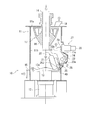
- FIG. 2 is a cross-sectional view showing the main configuration of a crusher provided with a crushing roller unit with a roller journal protector according to an embodiment of the present invention.
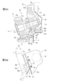
- 3A and 3B are views showing a side surface of a crushing roller unit with a roller journal protector according to an embodiment of the present invention, FIG. 3A is an overall cross-sectional view thereof, and FIG. 3B is a side view of an essential part thereof. .
- FIG. 1 is a perspective view showing a part of a configuration of a crusher provided with a crushing roller unit with a roller journal protector according to an embodiment of the present invention.
- FIG. 2 is a cross-sectional view showing the main configuration of a crusher provided with a crushing roller unit with a roller journal protector according to an embodiment of the present invention.
- 3A and 3B are views showing a side surface of
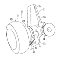
- FIG. 4 is a perspective view showing a state in which the pulverizing roller unit with a roller journal protector according to the embodiment of the present invention is viewed from an oblique front side.
- FIG. 5 is a perspective view showing a main part viewed from an oblique front side with the grinding roller of the grinding roller unit with a roller journal protector according to an embodiment of the present invention removed.
- 6A and 6B are perspective views showing a state of the pulverizing roller unit with a roller journal protector according to one embodiment of the present invention as seen from the lower rear side, FIG. 6A is an overall perspective view, and FIG. It is the principal part perspective view [VIB part enlarged view of Drawing 6A].
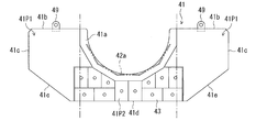
- FIG. 7 is a front view of an apron-like panel (mounting panel member) of the roller journal protector according to the embodiment of the present invention.
- the pulverizing roller unit provided with the roller journal protector according to the present invention and the pulverizer provided with the pulverizing roller unit are for pulverizing and pulverizing solid raw materials.
- coal pulverizers that pulverize and pulverize carbon-containing solid fuels such as coal as raw materials.
- various solid materials such as Petro Coke, which is the remaining residue of biomass and crude oil, can be applied as the solid material to be pulverized. Note that “up and down” described below indicates up and down in the vertical direction (gravity direction), and “left and right” indicates directions opposite to each other in the horizontal direction with respect to a subject.
- a crusher 10 also called a vertical mill, includes a housing 11 having a vertical cylindrical hollow shape, and a solid material such as coal to be pulverized is placed on the central axis of a ceiling portion 11 a of the housing 11.
- An input pipe 14 for supplying material raw materials is arranged.
- a pulverizing table 13 for pulverizing the solid raw material charged from the charging tube 14 is disposed on the pedestal 12 directly below the charging tube 14.
- the crushing table 13 is rotationally driven around a vertical axis along the central axis by a driving device (not shown).
- annular pulverizing surface 13a On the upper surface in the vertical direction of the pulverizing table 13, an annular pulverizing surface 13a is formed concentrically with the central axis, and a plurality of (for example, two or three) facing the pulverizing surface 13a above the pulverizing surface 13a in the vertical direction. ) Crushing rollers 21 are arranged at equal intervals in the circumferential direction. Each crushing roller 21 is rotatably supported at a tip end portion of a journal shaft (rotation support shaft) 22 arranged so as to incline downward in the vertical direction from the peripheral wall 11b of the housing 11 toward the central axis.
- journal shaft rotation support shaft
- the journal shaft 22 is supported by the journal head 23, and the pulverizing roller unit 20 includes the pulverizing roller 21, the journal shaft 22, and the journal head 23.
- a swing shaft (pivot pin) 24 extending in the tangential direction on the outer periphery of the pulverizing table 13 is provided on the journal head 23 so as to protrude from the housing 11 to the left and right (one and the other in the tangential direction).
- the crushing roller unit 20 is supported by the peripheral wall 11b through the pivot pin 24 so as to be swingable in a direction in which the crushing roller 21 approaches the crushing surface 13a and in a direction away from the crushing surface 13a.
- the journal head 23 is formed with a protruding portion 23a protruding downward in the vertical direction, and the peripheral wall 11b of the housing 11 is equipped with a stopper 25.
- the tip of the stopper 25 comes into contact with the protrusion 23a, the approach of the grinding roller 21 to the grinding surface 13a is restricted.
- the stopper 25 is driven forward and backward by the actuator 26 to adjust the tip position thereof, and adjusts the closest approach position of the grinding roller 21 to the grinding surface 13a.
- an urging device 27 for applying a load for pulverizing the solid matter to the pulverizing roller 21 is equipped.
- the urging device 27 includes a hydraulic cylinder 28 fixed to the peripheral wall 11 b and a plunger 29 driven in the axial direction by the hydraulic cylinder 28.
- An arm portion 23b extends above the journal head 23.
- an inlet port 15 is provided in the outer periphery of the crushing table 13 and into which the carrier gas is sent.
- air compressed by a primary blower (not shown) is sent into the housing 11 as a carrier gas from the inlet port 15, and the inside of the housing 11 is in a high-pressure atmosphere.
- a rotary separator (classifying device) 17 for classifying the pulverized solid matter (hereinafter also referred to as fine powder or pulverized product) with a classifying blade 16 is provided at the upper part of the housing 11 and is located on the outer periphery of the input tube 14. It is done.
- an outlet port 18 for discharging the classified pulverized material is provided in the ceiling portion 11a of the housing 11.
- the solid material pulverized by the pulverizing roller 21 becomes a pulverized material.
- the carrier gas is sent into the housing 11 from the inlet port 15. Due to the upward swirling flow of the carrier gas generated by the vane 32a at the outlet 32, the pulverized product rises while being dried.
- the raised pulverized product is classified by the rotary separator 17 into a fine powder having a smaller particle size and a coarse powder having a larger particle size. At that time, the coarse powder is classified and distributed by the rotary separator 17 in order to suppress the conveyance from the pulverizer to another device, and is returned to the pulverization table 13 and re-pulverized.
- the fine powder passes through the rotary separator 17, rides on the flow of the carrier gas, is discharged from the outlet port 18, and is conveyed from the pulverizer to another device.
- an opening 11c is formed in the peripheral wall 11b of the housing 11, and the journal head 23 is disposed in the opening 11c, and a pivot pin 24 protruding left and right is connected to the edge of the opening 11c. Is supported by the peripheral wall 11b.
- a cover 30 that protrudes in the radial direction of the peripheral wall 11 b is attached to the opening 11 c so as not to interfere with the journal head 23, and partitions the inside and the outside of the housing 11.
- the grinding roller 21 has a roller housing 21a having a shaft-like portion 21b, and a roller main body portion 21c that is externally fitted to the roller housing 21a and is detachable. Further, the journal head 23 is provided with a roller support portion 23c for supporting the crushing roller 21, and the projection portion 23a, the arm portion 23b, and the pivot pin 24 project downward, upward, and left and right sides from the roller support portion 23c. These are in contact with and supported by the stopper 25, the plunger 29, and the peripheral wall 11b.
- journal shaft 22 on the cover 30 side is coupled to the roller support portion 23 c of the journal head 23.
- a roller housing 21a of the crushing roller 21 is rotatably attached to the end (other end side) of the journal shaft 22 on the central axis side.
- the axis of the journal shaft 22 is disposed so as to be inclined downward from the peripheral wall 11b of the housing 11 toward the central axis, and the inclination angle ⁇ is, for example, about 15 to 40 degrees.
- the carrier gas sent into the housing 11 by a blower (not shown) connected to the inlet port 15 is provided between the outer periphery of the crushing table 13 and the peripheral wall 11b of the housing 11 as indicated by an arrow A1 in FIG. 3A.
- the air is blown upward from the carrier gas outlet 32 in the vertical direction.
- a vane 32a is provided at a portion of the carrier gas outlet 32 on the outer periphery of the pulverizing table 13, and rotational force is applied to the carrier gas blown upward from the carrier gas outlet 32 in the vertical direction while rotating together with the pulverizing table 13.
- a swirling flow directed upward in the vertical direction is formed in the housing 11.
- the roller housing 21a of the crushing roller 21 and the roller support portion 23c of the journal head 23 are disposed immediately above the carrier gas outlet 32, and the pivot pin 24 is also positioned. Therefore, the carrier gas blown upward from the lower side in the vertical direction is blown toward the surface of the roller housing 21a, the roller support portion 23c, and the pivot pin 24 that are positioned downward in the vertical direction.
- the roller journal protector 40 has an apron-like panel (attachment panel member) 41 that is detachably attached to the roller support portion 23c and the projection 23a of the journal head 23, and a base end portion 42a that has an apron shape.
- the shield 42 is fixed to the panel 41 and is disposed and attached so as to surround the lower portion of the shaft-like portion 21b of the roller housing 21a.
- the apron-like panel 41 and the shield 42 are made of steel (for example, SS400, low alloy steel).
- the apron-like panel 41 is a flat plate, is attached to the roller support portion 23c so as to expand around the roller support portion 23c, and has a function as an attachment member for attaching the shield 42 to the roller support portion 23c and the like. It also has a function of protecting the roller support 23c, the protrusion 23a, and the pivot pin 24 from collision of fine powder.
- FIG. 7 is a front view of the apron-like panel 41, which is a plate-like member that extends vertically in the vertical direction and the left-right direction of the paper surface, with the upper side of the paper surface being vertically attached in the mounted state.
- the apron-like panel 41 has a concave edge portion 41a formed in a substantially semicircular shape corresponding to the outer periphery of the lower half portion of the substantially semi-cylindrical vertical direction of the roller support portion 23c. Is formed.
- the apron-like panel 41 extends in a planar shape from both sides in the horizontal direction (direction in the attached state to the journal head 23) and downward from the concave edge portion 41a.
- the upper edge portions 41b and 41b and the both side edge portions 41c and 41c located on both sides in the horizontal direction of the concave edge portion 41a are formed in a substantially straight shape, and the lower lower edge portion of the concave edge portion 41a is a horizontal intermediate lower edge portion. It is formed in a bent line shape composed of 41d and inclined side lower edge portions 41e and 41e on both sides thereof.
- Such an apron-like panel 41 has a concave edge portion 41a along the outer periphery of the lower half portion of the roller support portion 23c facing the substantially semi-cylindrical vertical direction, and
- the roller support portion is arranged in a direction perpendicular to the axis of the roller support portion 23c (the axis of the journal shaft 22) so that the plane extends from the outer periphery of the roller support portion 23c to a substantially constant distance. 23c.
- the apron-like panel 41 is a part of the opening 11c of the peripheral wall 11b of the housing 11, that is, the lower half of the roller support 23c. It is arranged and attached so as to block the regions on both sides in the horizontal direction (direction in the attached state to the journal head 23), and the lower half and the regions below these both sides in the vertical direction.
- the apron-like panel 41 includes a lateral region (mainly an upper edge portion) extending in the horizontal direction (width direction of the opening 11 c) and downward from each side of the outer periphery of the lower half of the roller support portion 23 c.
- 41b a trapezoidal region surrounded by the side edge 41c and the lower side edge 41e) 41P1 and 41P1, and a lower region extending mainly below the outer periphery of the lower half of the roller support portion 3c in the mounted state (mainly the concave edge 41a and the lower middle) It can be divided into 41P2 (regions between the side regions 41P1 and 41P1 surrounded by the edge portion 41d).
- the apron-like panel 41 is a hard tile that suppresses the occurrence of wear due to the collision of the fine powder.
- a ceramic tile 43 made of hard ceramic is attached.
- This ceramic tile 43 has a lower region 41P2 (which can also be referred to as a “region portion having a width located directly below the axis of the roller support portion 23c)” 41P2, which is a region where the collision frequency of fine powder is relatively high.
- the main body is mounted so that a gap between the ceramic tiles 43 is narrowed only on a part of the surface.
- the mutual gap is determined from the difference in thermal expansion between the ceramic tile 44 and the apron-like panel 41 and the ease of construction, it is preferable to make the gap as narrow as possible in order to protect the apron-like panel 41.
- the mounting location of the ceramic tile 43 may be set as necessary. For example, it is conceivable to shift the mounting location to the swirl downstream side according to the swirl direction of the carrier gas. If necessary, it may be mounted on the entire surface.
- the material of the ceramic style 43 is not particularly limited as long as it is able to protect the apron-like panel 41 that is a base material from collision of fine powder that is sprayed on a carrier gas stream. For example, alumina, silica, zirconia , Magnesia, silicon carbide, silicon nitride, etc., and mixtures thereof can be used.
- a seat formed on the roller support portion 23c is provided on the back side of the concave edge portion 41a of the apron-like panel 41 (the back side opposite to the surface on which the carrier gas is blown).
- a mounting seat 46 fixed to the surface 45 with fastening bolts 47 is formed.
- the mounting seat 46 is formed so as to protrude from the back side at two locations, the upper and lower portions, on the left and right sides of the roller support portion 23 c with respect to the concave edge portion 41 a, and is hidden behind the fastening bolt 47.
- Bolt holes (not shown) are formed.
- a protector ring (protective wall portion) 48 for protecting the head of the fastening bolt 47 to be mounted from collision of fine powder is formed.
- the protector ring 48 is an annular flange wall located around the head of the fastening bolt 47 to which the protector ring 48 is attached.
- the protector ring 48 has a height higher than the height of the head of the fastening bolt 47. This prevents the parts from being damaged by wear and hindering replacement work.
- each upper edge portion 41b located on both sides of the apron-like panel 41 with a concave edge portion 41a is provided with a suspension hook hole 49, which enables suspension support during replacement work.
- screw holes (not shown) are formed in the upper and lower portions of the seat surface 45 provided in the roller support portion 23c corresponding to the mounting seat 46.
- the apron-like panel 41 is suspended using hook holes 49, each mounting seat 46 is disposed at a predetermined position on the corresponding seat surface 45, the fastening bolt 47 is inserted into the bolt hole of the mounting seat 46, and It is attached to the journal head 23 by being screwed into a screw hole of the seating surface 45.
- the head of the fastening bolt 47 is surrounded by a protector ring 48, and the lower half of the roller support 23c in the vertical direction is protected by the apron-like panel 41 and rides on the carrier gas flow. It is protected to suppress wear from fine powder that is sprayed and collides.
- the shield 42 surrounds the semi-cylindrical region inside the peripheral wall 11b of the housing 11 at the lower portion in the vertical direction of the shaft-like portion 21b of the crushing roller 21. It is formed in the shape of a half frustum. As shown in FIG. 7, the shield 42 is disposed such that the base end portion 42a on one side is along the concave edge portion 41a, and is fixed by welding or the like in the vicinity of the concave edge portion 41a.
- the shield 42 is formed in a semi-conical frustum shape (half-polygonal frustum shape) with the other end 42b extending toward the roller body 21c, and surrounds the lower portion in the vertical direction of the shaft 21b. .
- the fine powder is blown onto the lower portion of the shaft-like portion 21b in the vertical direction while riding the carrier gas stream from the carrier gas outlet 32, but this fine powder collides with the shield 42. Cover the part to protect it from fine powder collisions.
- the shield 42 is formed in a semi-frustum shape by combining a plurality of flat panel panels.
- a ceramic tile 44 made of hard ceramic is mounted on the surface of the shield 42 (the surface on the side on which the carrier gas from the carrier gas outlet 32 hits) as a hard tile that protects the shield 42 from collision of fine powder.
- the ceramic tiles 44 are mounted on the entire surface of the shield 42 so that the gap between the ceramic tiles 44 is narrowed. The mutual gap is determined from the difference in thermal expansion between the ceramic tile 44 and the shield 42 and the ease of construction, but it is preferable to make the gap as narrow as possible in order to protect the shield 42.
- the mounting location of the ceramic tile 44 may be set as necessary, and may be partially mounted.
- the shield 42 of this embodiment is formed by combining a plurality of flat plates, a flat ceramic tile 44 can be easily mounted.
- the apron-like panel 41, which is the base material of the ceramic tiles 43 and 44, and the shield 42 are mounted on the surface, for example, by generally attaching a plug that fits into the mounting holes of the ceramic tiles 43 and 44. A method may be applied.
- the shape of the shield 42 is a half frustum shape, and the outer periphery of the shaft-like portion 21b of the crushing roller 21 is expanded toward the roller main body portion 21c, so that the base end portion 42a is extended to the tip end portion 42b.
- the diameter is gradually increasing.
- a vertically lower region (in this case, one flat panel portion at the bottom) 42c in a semipyramidal shape in the attached state of the shield 42 is directed from the base end portion 42a to the tip end portion 42b (the central portion of the housing 11).
- the inner surface (surface) of the shield 42 is inclined downward from the horizontal direction toward the distal end portion 42b from the base end portion 42a at an angle greater than the lower region 42c.
- the upward surface on the opposite side is inclined at an angle equal to or greater than the angle of repose of the fine powder at any location. Since the angle of repose of the fine powder is determined according to the fine powder and the surface state of the shield 42, it is preferable to set the angle ⁇ according to the fine powder to be manufactured.
- angle ⁇ that covers the portion of the carrier gas that is blown in the air flow of the carrier gas and that is exposed to the fine powder and that has a margin greater than the repose angle of the fine powder within the arrangement space in the housing 11.
- the angle ⁇ is preferably in the range of 40 degrees to 50 degrees.
- the roller journal protector 40, the crushing roller unit 20 and the crusher 10 having the roller journal protector 40 according to the embodiment of the present invention are configured as described above, the apron-like panel (mounting panel member) 41 is used to form the journal head 23.
- the shield 42 detachably attached to the shaft covers the lower half of the vertical direction where the fine powder blown on the airflow of the carrier gas hits the shaft-shaped portion 21b of the crushing roller 21, and the shaft-shaped portion 21b from the collision of the fine powder. Protect. Thereby, since the abrasion of the shaft-like portion 21b of the grinding roller 21 due to the collision of the fine powder can be prevented, the life of the device can be extended.
- the apron-like panel 41 has a part of the opening 11c of the peripheral wall 11b of the housing 11 below the roller support 23c in the vertical direction, that is, the lower half of the roller support 23c in the vertical direction and both sides thereof. Since the region is attached so as to protect against collision of fine powder sprayed on the carrier gas flow, in addition to the function of attaching the shield 42 to the roller support 23c etc., the roller support 23c, the projection 23a, It functions to protect the pivot pin 24 from collision of fine powder sprayed on the carrier gas stream. As a result, the wear of the roller support portion 23c, the protrusion 23a, and the pivot pin 24 due to the collision of the fine powder can be prevented, so that the life of the device can be extended.
- the ceramic tile 43 is mounted mainly on the lower region 41P2, which is a region where the collision frequency of the fine powder is relatively high, and is limited to a part of the surface. Cost can be suppressed. Of course, the same effect can be obtained if the ceramic tile 44 can be attached to the shield 42 only in a region where the collision frequency of the fine powder is relatively high.
- the fine powder raised by the carrier gas carrier gas adheres to the inner surface (upper surface) of the shield 42, but the inner surface of the shield 42 is inclined at an angle greater than the repose angle of the fine powder at any location.
- the attached fine powder falls by gravity while sliding on the inner surface of the shield 42. Thereby, it is possible to prevent fine powder from accumulating on the inner surface of the shield 42.
- roller journal protector 40 is fastened by fixing the mounting seat 46 formed on the back surface of the apron-like panel 41 to the seat surface 45 of the roller support portion 23c with the fastening bolt 47, the attachment / detachment of the fastening bolt 47 can be performed. Therefore, the roller journal protector 40 (shield 42 and apron-like panel 41) can be easily replaced.
- a protector ring 48 is formed around the bolt hole of the mounting seat 46 so that the head of the fastening bolt 47 to be mounted is protected from collision of fine powder sprayed on the carrier gas stream.
- the head of the fastening bolt 47 is prevented or suppressed from being worn by the collision of the fine powder, the head of the fastening bolt 47 is worn and the detachable tool cannot be used.
- the fastening bolt 47 can be removed without hindrance.
- the maintenance management of the roller journal protector 40 is preferably performed by the following method.
- the crusher 10 normally performs periodic inspections such as periodic inspections, but at this periodic inspection timing or at other irregular inspection timings, the state of the roller journal protector 40 needs to be checked and replaced. It is determined whether or not it is in a consumed state (state determination step).
- state determination step when it is determined that the state of the roller journal protector 40 is an exhausted state that needs to be replaced, or when it is determined that it is preferable to replace the estimated state of use in the future.
- the roller journal protector 40 is replaced with a proper product prepared in advance (exchange process). Of course, if it is determined that the roller journal protector 40 does not need to be replaced until the next inspection, the replacement may not be performed.
- roller journal protector 40 that has been determined to be exhausted in the state determination step and removed by replacement, for example, repair regeneration processing such as replacement and replacement of hard tiles is performed, and used in the next replacement. Prepare as an appropriate product (appropriate product) before replacement. If repair and regeneration processing is impossible, prepare a new one.
- Appropriate products of the roller journal protector 40 include new products and regenerated products that have been repaired and repaired.
- the state of wear of the roller journal protector 40 is determined at the inspection timing of the pulverizer 10, and the roller journal protector 40 is efficiently and appropriately maintained easily by replacing it with a proper one if necessary. Therefore, the roller journal portion 20J of the crushing roller unit 20 can be protected for a long period of time, and the performance of the crusher 10 can be ensured for a long period of time, and the mechanical life can be extended.
- the roller journal protector 40 is configured to be always replaced with the roller journal protector 40 prepared for replacement at the regular inspection timing without determining the wear state. For the roller journal protector 40 removed by replacement, If reprocessing is performed as appropriate and stored for replacement, the processing can be performed in a short time, and the operation stop time of the pulverizer 10 for maintenance management of the roller journal protector 40 can be further shortened.
- the ceramic tiles 43 and 44 made of hard ceramic are used as the hard tiles covering the surfaces of the apron-like panel 41 and the shield 42.
- the hard tiles are not limited to this, and the required durability strength is obtained. Any material can be used if it is made of a wear-resistant material.
- the base material itself of the apron-like panel 41 and the shield 42 is preferably made of a material having high durability. In this case, a hard tile may be unnecessary depending on the durability strength of the base material.
- the apron-like panel 41 and the shield 42 are formed of a general steel material, and the material cost can be kept low by mounting a hard tile on a necessary portion of the surface.
- the shield 42 is formed in a semi-frustum shape by combining a plurality of flat panel panels so that the flat ceramic tile 44 can be easily mounted.
- the curved shape may be formed in accordance with the shape of the shaft portion 21b of the roller housing 21a.
- the shield 42 is formed in a semi-frustum shape, but may be formed in a semi-cylindrical shape as long as it is protected from the collision of fine powder sprayed on the carrier gas flow.
- the protective wall part was comprised by the protector ring which is an annular collar wall
- a protective wall part is located around the head of the fastening bolt 47 with which it was mounted
Landscapes
- Engineering & Computer Science (AREA)
- Food Science & Technology (AREA)
- Crushing And Grinding (AREA)
- Disintegrating Or Milling (AREA)
Abstract
ローラジャーナルへの微粉体の衝突を防止して摩耗発生を抑制すると共に、維持管理に関する作業性を向上させ、母材を損傷させるおそれも低減させる。 粉砕機のハウジング(11)の周壁(11b)に配置されたジャーナルヘッド(23)と、粉砕テーブル(13)の上面で固形物を粉砕するローラ本体部(21c)を有する粉砕ローラ(21)とを備え、軸状部(21b)の下方に、上方へ向けて搬送ガスを吹き出す搬送ガス吹出口(32)が配置された粉砕ローラユニット(20)に装備され、ローラジャーナル部(20J)を保護するプロテクタであって、ジャーナルヘッド(23)に取り付けられる取付パネル部材(41)と、軸状部(21b)の下側部分を包囲しうる半錐台形状に形成され、基端部(42a)が取付パネル部材(41)に固定されて、搬送ガス吹出口(32)からの搬送ガスが当たる部分を覆って微粉体の衝突から保護するシールド(42)と、を有する。
Description
本発明は、石炭など炭素含有固体燃料をはじめとした固形物を粉砕して微粉化する粉砕機に装備されたローラジャーナルを保護するローラジャーナルプロテクタ,このローラジャーナルプロテクタを備えた粉砕ローラユニット及びこの粉砕ローラユニットを備えた粉砕機、並びに、ローラジャーナルプロテクタの保守管理方法に関するものである。
従来、粉砕機(ミル)を用いて、石炭など炭素含有固体燃料を微粉状に粉砕した微粉炭を燃料とする火力発電ボイラ等の微粉炭燃焼装置が知られている。かかる粉砕機は、給炭機より送られてきた原炭を、粉砕ローラと粉砕テーブルとによって押圧することで粉砕(微粉炭を製造)し、粉砕テーブルとケーシング(ハウジング)との隙間から吹き出す微粉炭の搬送用に用いる搬送ガス(空気や不活性ガス)の流れを利用して、粉砕機内より燃料供給配管を介してボイラ側に搬送する(特許文献1,2参照)。
このような粉砕機の内部では、微粉炭等の微粉体が搬送ガス(空気や不活性ガス)の流れに乗って吹き上げられる。特許文献1には、吹き上げられた微粉体が、粉砕ローラが貫通するケーシング(ハウジング)の孔部から外部に漏出しないようにすることを目的とした技術が記載されている。特許文献2には、吹き上げられた微粉炭が粉砕ローラの軸保持部を閉塞するラビリンスシール間に詰まることのないようにすることを目的とした技術が記載されている。
ところで、搬送ガスの流れに乗って吹き上げられる微粉体の一部は、粉砕ローラの軸状部や粉砕ローラを支持するローラ支持部等のローラ及びジャーナル(ローラジャーナル)の一部に衝突するため、これらの箇所の摩耗対策が課題となっている。
これに対し、母材表面の摩耗が発生する箇所に複数枚の耐摩耗性鋼板を直接母材に張り付けて、摩耗を抑制する対策を取ることができる。しかしながら、この場合、摩耗した複数枚の耐摩耗性鋼板を交換する作業の際に、母材を損傷させない様に耐摩耗性鋼板を手作業で張り替えるので、作業性が悪く、粉砕機の再稼働までに時間がかかり、粉砕機の稼動率を大きく低下させるおそれがあり、また、鋼板を剥す際に母材表面の一部を一緒に剥し、母材を損傷させてしまうおそれもある。
本発明は、このような課題に着目して創案されたもので、ローラジャーナルへの微粉体の衝突を防止して摩耗発生を抑制すると共に、ローラジャーナルの維持管理に関する作業性が良く、母材を損傷させるおそれも低減することができるようにした、ローラジャーナルプロテクタ,粉砕ローラユニット及び粉砕機、並びに、ローラジャーナルプロテクタの保守管理方法を提供することを目的とする。
(1)上記の目的を達成するために、本発明のローラジャーナルプロテクタは、粉砕機のハウジングの周壁に形成された開口部に配置され、揺動軸によって前記周壁に揺動可能に支持されたジャーナルヘッドと、前記ジャーナルヘッドのローラ支持部に軸状部を有するローラジャーナル部を介して取り付けられ、前記ハウジング内で回転する粉砕テーブルの上面に接触して連れ回りして固形物を微粉体に粉砕するローラ本体部を有する粉砕ローラと、を備え、前記軸状部の鉛直方向下方に、上方へ向けて搬送ガスを吹き出す搬送ガス吹出口が配置された、粉砕ローラユニットに装備され、前記ローラジャーナル部を、前記搬送ガスとともに搬送される前記微粉体の衝突から保護するプロテクタであって、前記ジャーナルヘッドに取り付けられる取付パネル部材と、前記軸状部の鉛直方向下側部分を包囲する半錐台形状に形成され、基端部が前記取付パネル部材に固定されて、先端部が前記ローラ本体部側に向けて延設され、前記搬送ガス吹出口からの搬送ガスが当たる部分を覆って前記微粉体の衝突から保護するシールドと、を有することを特徴としている。
(2)前記シールドの取付状態における前記半錐台形状の鉛直方向下方領域が、前記基端部から前記先端部へ向けて前記微粉体の安息角以上の角度で水平面より下降傾斜するように形成されていることが好ましい。
(3)前記シールドは、複数の平板が結合されて前記半錐台形状に形成されていることが好ましい。
(4)前記シールドの前記搬送ガス吹出口からの前記搬送ガスが当たる側の表面には、前記シールドを前記微粉体の衝突から保護する硬質タイルが装着されていることが好ましい。
(3)前記シールドは、複数の平板が結合されて前記半錐台形状に形成されていることが好ましい。
(4)前記シールドの前記搬送ガス吹出口からの前記搬送ガスが当たる側の表面には、前記シールドを前記微粉体の衝突から保護する硬質タイルが装着されていることが好ましい。
(5)前記取付パネル部材は、前記ローラ支持部の鉛直方向下方において前記開口部の一部を塞ぐように配置され、前記ローラジャーナル部及び前記揺動軸の少なくとも一部を前記微粉体の衝突から保護することが好ましい。
(6)前記取付パネル部材は、取付状態で鉛直方向上方となる部分に前記ローラ支持部の下半部外周形状に応じて形成されると共に該下半部外周に沿って配置される半円形状の凹縁部を備え、前記シールドの前記基端部は、前記凹縁部に近接して固定され、取付状態で前記シールドの鉛直方向下方に位置し前記搬送ガス吹出口からの搬送ガスが当たる側の表面には、前記取付パネル部材を前記微粉体の衝突から保護する硬質タイルが装着されていることが好ましい。
(7)前記取付パネル部材は、取付状態で前記ローラ支持部の前記下半部外周の各側方から前記開口部の幅方向且つ鉛直方向下方に延びる側方領域と、取付状態で前記ローラ支持部の前記下半部外周の鉛直方向下方に延びる下方領域とを有し、前記硬質タイルは、前記下方領域の少なくとも一部に装着されていることが好ましい。
(8)前記取付パネル部材の前記搬送ガス吹出口からの搬送ガスが当たる側の表面とは反対側となる裏面に取付座が形成され、前記ローラ支持部に形成された座面と前記取付座とは締結用ボルトで着脱可能に取り付けられ、前記取付座のボルト穴の周囲に、前記締結ボルトの頭部を前記微粉体の衝突から保護する保護壁部が形成されていることが好ましい。
(9)本発明の粉砕ローラユニットは、粉砕機のハウジングの周壁に形成された開口部に配置され、揺動軸によって前記周壁に揺動可能に支持されたジャーナルヘッドと、前記ジャーナルヘッドのローラ支持部に軸状部を有するローラジャーナル部を介して取り付けられ、前記ハウジング内で回転する粉砕テーブルの上面に接触して連れ回り転動して固体物質を微粉体に粉砕するローラ本体部を有する粉砕ローラと、を備え、前記軸状部の鉛直方向下方に、上方へ向けて搬送ガスを吹き出す搬送ガス吹出口が配置された、粉砕ローラユニットであって、前ローラジャーナル部に、上記の(1)~(8)の何れかに記載のローラジャーナルプロテクタが取り付けられたことを特徴としている。
(10)本発明の粉砕機は、ハウジング内に鉛直方向に沿う軸心回りに駆動回転可能に支持される粉砕テーブルと、上記の(9)記載の粉砕ローラユニットと、を有することを特徴としている。
(11)本発明のローラジャーナルプロテクタの保守管理方法は、上記の(1)~(8)の何れかに記載のローラジャーナルプロテクタの保守管理方法であって、粉砕機の点検タイミングで実施し、前記ローラジャーナルプロテクタの状態を確認し交換が好ましい消耗状態であるか否かを判定する状態判定工程と、前記状態判定工程で前記ローラジャーナルプロテクタの状態が消耗状態であると判定されたら、前記ローラジャーナルプロテクタを事前準備した適正品に交換する交換工程とを有することを特徴としている。
(12)前記状態判定工程で消耗状態であると判定されて、取り外した前記ローラジャーナルプロテクタに対しては、補修して再生可能な状態であるか否かを判定し、補修再生可能であれば次回交換工程で交換可能な前記適正品として補修再生処理を実施して事前準備することが好ましい。
(12)前記状態判定工程で消耗状態であると判定されて、取り外した前記ローラジャーナルプロテクタに対しては、補修して再生可能な状態であるか否かを判定し、補修再生可能であれば次回交換工程で交換可能な前記適正品として補修再生処理を実施して事前準備することが好ましい。
本発明によれば、シールドが、粉砕ローラのローラジャーナル部の軸状部における搬送ガス(空気や不活性ガス)が衝突する部分を覆っているので、搬送ガスの流れに乗って吹き上げられた微粉体の衝突による軸状部の摩耗発生を抑制することができる。また、ローラジャーナルプロテクタは取付パネル部材によりジャーナルヘッドに容易に着脱可能に取り付けられるので、ジャーナルヘッドの維持管理に関する作業性が良く、維持管理に関する作業による粉砕機の再稼働までの期間が短縮され、粉砕機の稼動率の低下を抑制し、交換する作業の際に母材を損傷させるおそれも低減できる。
さらに、ローラジャーナルプロテクタの取付パネル部材を、ローラ支持部の鉛直方向下方においてハウジングの周壁の開口部の一部を塞ぐように配置されるエプロン状パネルとして構成し、エプロン状パネルによりローラジャーナル部のローラ支持部及び揺動軸を塞ぐことにより、搬送ガスの流れに乗って吹き上げられた微粉体の衝突によるローラ支持部及び揺動軸の摩耗発生を抑制することができる。また、取付パネル部材(エプロン状パネル)において、微粉体の衝突する部分に耐摩耗鋼板等の耐摩耗材を脱着可能に設けることで、摩耗への耐久力が向上し、ジャーナルヘッドの維持管理に関する作業の頻度を低減し、交換作業を容易にできる。また、作業により母材を損傷させるおそれを低減することができる。
以下、図面を参照して、本発明の実施の形態を説明する。
なお、以下に示す実施形態はあくまでも例示に過ぎず、以下の実施形態で明示しない種々の変形や技術の適用を排除する意図はない。以下の実施形態の各構成は、それらの趣旨を逸脱しない範囲で種々変形して実施することができると共に、必要に応じて取捨選択することができ、あるいは適宜組み合わせることが可能である。
なお、以下に示す実施形態はあくまでも例示に過ぎず、以下の実施形態で明示しない種々の変形や技術の適用を排除する意図はない。以下の実施形態の各構成は、それらの趣旨を逸脱しない範囲で種々変形して実施することができると共に、必要に応じて取捨選択することができ、あるいは適宜組み合わせることが可能である。
また、本発明にかかるローラジャーナルプロテクタを備えた粉砕ローラユニット及び粉砕ローラユニットを備えた粉砕機は、固形物原材料を粉砕して微粉化するためのものであり、代表的なものは、固形物原材料として石炭など炭素含有固体燃料を粉砕して微粉化する石炭粉砕機がある。粉砕する固形物原材料としては、この他、バイオマスや原油の残りカスであるペトロコーク等の種々の固形物を適用できる。
なお、以下で説明する「上下」とは、鉛直方向(重力方向)での上下を示し、また、「左右」とはある主体に対して水平方向の互いに逆向きの方向を示している。
なお、以下で説明する「上下」とは、鉛直方向(重力方向)での上下を示し、また、「左右」とはある主体に対して水平方向の互いに逆向きの方向を示している。
〔粉砕機の構成〕
まず、図2を参照して、本実施形態にかかる粉砕機10の構成を説明する。図2に示すように、竪型ミルとも呼ばれる粉砕機10は、竪型の円筒中空形状をなすハウジング11を備え、ハウジング11の天井部11aの中心軸線上には、粉砕すべき石炭等の固形物原材料を投入する投入管14が配置される。投入管14の直下の台座12上には、投入管14から投入された固形物原材料を粉砕する粉砕テーブル13が配置される。粉砕テーブル13は、図示しない駆動装置により前記中心軸線に沿った鉛直方向の軸心回りに回転駆動される。
まず、図2を参照して、本実施形態にかかる粉砕機10の構成を説明する。図2に示すように、竪型ミルとも呼ばれる粉砕機10は、竪型の円筒中空形状をなすハウジング11を備え、ハウジング11の天井部11aの中心軸線上には、粉砕すべき石炭等の固形物原材料を投入する投入管14が配置される。投入管14の直下の台座12上には、投入管14から投入された固形物原材料を粉砕する粉砕テーブル13が配置される。粉砕テーブル13は、図示しない駆動装置により前記中心軸線に沿った鉛直方向の軸心回りに回転駆動される。
粉砕テーブル13の鉛直方向の上面には、中心軸線と同心に環状の粉砕面13aが形成され、粉砕面13aの鉛直方向上方に、粉砕面13aと対向して複数(例えば、2個或いは3個)の粉砕ローラ21が周方向に均等間隔で配置されている。各粉砕ローラ21は、ハウジング11の周壁11bから中心軸線側へ鉛直方向下方に傾斜するように配置されたジャーナル軸(回転支持軸)22の先端部に回転自在に支持されている。
ジャーナル軸22は、ジャーナルヘッド23に支持されており、粉砕ローラ21,ジャーナル軸22及びジャーナルヘッド23から、粉砕ローラユニット20が構成されている。ジャーナルヘッド23には、粉砕テーブル13の外周の接線方向に延びる揺動軸(ピボットピン)24が左右(接線方向の一方及び他方)にハウジング11より突出して設けられている。粉砕ローラユニット20は、このピボットピン24を介して、粉砕ローラ21が粉砕面13aに接近する方向と粉砕面13aから離隔する方向とに、周壁11bに揺動可能に支持されている。
図2に示すように、ジャーナルヘッド23には鉛直方向下方側に突設された突起部23aが形成され、ハウジング11の周壁11bにはストッパ25が装備されている。ストッパ25の先端が突起部23aに当接すると粉砕ローラ21の粉砕面13aへの接近が規制される。ストッパ25は、アクチュエータ26によって進退駆動されることによって、その先端位置が調整され、粉砕ローラ21の粉砕面13aへの最接近位置を調整する。
また、粉砕ローラ21に固形物を粉砕するための荷重を加える付勢装置27が装備される。付勢装置27は、周壁11bに固定された油圧シリンダ28と、油圧シリンダ28により軸方向へ駆動されるプランジャ29とを備える。ジャーナルヘッド23の上部にはアーム部23bが延びており、プランジャ29の先端がアーム部23bに押し付けられることにより、粉砕ローラ21に粉砕面13a上の固形物を粉砕する下向き(粉砕面13aに向く)荷重が加えられる。
ハウジング11の下部には、粉砕テーブル13の外周辺に位置して搬送ガスが送り込まれる入口ポート15が設けられる。本実施形態では図示しない一次送風機によって圧縮された空気が、この入口ポート15から搬送ガスとしてハウジング11内に送り込まれ、ハウジング11内が高圧雰囲気とされる。
ハウジング11の上部には、投入管14の外周辺に位置して、粉砕された固形物(以下、微粉体或いは粉砕物とも言う)を分級ブレード16によって分級するロータリセパレータ(分級装置)17が設けられる。また、ハウジング11の天井部11aには、分級した粉砕物を排出する出口ポート18が設けられている。
粉砕ローラ21により粉砕された固形物は粉砕物となり、入口ポート15に接続された送風機(不図示)を駆動させることで入口ポート15からハウジング11内に搬送ガスが送り込まれ、後述する搬送ガス吹出口32のベーン32aによって発生する搬送ガスの上向き旋回流により、粉砕物は乾燥されつつ上昇する。この上昇した粉砕物は、ロータリセパレータ17により所定の粒径より小さい細粒粉と所定の粒径より大きい粗粉とに分級される。その際、粗粉は、粉砕機から別機器への搬送を抑制するために、ロータリセパレータ17により分級し分配され、再び粉砕テーブル13上に戻されて再粉砕が行われる。細粒粉は、ロータリセパレータ17を通過し、搬送ガスの流れに乗って出口ポート18から排出され、粉砕機より別機器へと搬送される。
〔粉砕ローラユニット及びその周辺の構成〕
このような粉砕機10に装備される粉砕ローラユニット20自体の概略構成は、従来のものとほぼ同様である。以下、図1,図3Aを参照して説明する。
このような粉砕機10に装備される粉砕ローラユニット20自体の概略構成は、従来のものとほぼ同様である。以下、図1,図3Aを参照して説明する。
図1,図3Aに示すように、ハウジング11の周壁11bには開口部11cが形成され、ジャーナルヘッド23は、この開口部11cに配置され、左右に突出したピボットピン24を開口部11cの縁部の周壁11bに揺動可能に支持されている。なお、開口部11cには、ジャーナルヘッド23と干渉しないように周壁11bの半径方向に突出したカバー30が装着され、ハウジング11の内部と外部とを区画している。
粉砕ローラ21は、軸状部21bを有するローラハウジング21aと、このローラハウジング21aに対して外嵌され着脱可能なローラ本体部21cとを有している。また、ジャーナルヘッド23は、粉砕ローラ21を支持するローラ支持部23cが備えられ、突起部23a,アーム部23b及びピボットピン24は、このローラ支持部23cから下方,上方及び左右側方に突設され、それぞれストッパ25,プランジャ29,周壁11bに当接、支持されている。
また、ジャーナル軸22におけるカバー30側の端部(一端側)は、ジャーナルヘッド23のローラ支持部23cと結合されている。そして、ジャーナル軸22における中心軸線側の端部(他端側)は、粉砕ローラ21のローラハウジング21aが回転自在に取り付けられている。なお、ジャーナル軸22の軸心は、ハウジング11の周壁11bから中心軸線側へ下方に傾斜するように配置されるが、この傾斜角度αは例えば15度から40度ほどである。
入口ポート15に接続された送風機(不図示)によりハウジング11内に送り込まれる搬送ガスは、図3Aに矢印A1で示すように、粉砕テーブル13の外周とハウジング11の周壁11bとの間に設けられた搬送ガス吹出口32から鉛直方向上方に向けて送風される。粉砕テーブル13の外周の搬送ガス吹出口32の部分には、ベーン32aが設けられ、粉砕テーブル13と共に回転しながら搬送ガス吹出口32から鉛直方向上方に向けて送風される搬送ガスに回転力を加えてハウジング11内に鉛直方向上方へ向かう旋回流を形成させる。
この搬送ガス吹出口32の直上位置には、粉砕ローラ21のローラハウジング21aやジャーナルヘッド23のローラ支持部23cが配置され、さらにピボットピン24も位置している。したがって、ローラハウジング21aやローラ支持部23cやピボットピン24の鉛直方向下向きに位置する面等に向けては、鉛直方向下側から上方へ向けて送風される搬送ガスが吹き付けられる。
ハウジング11内では、粉砕テーブル13上で粉砕ローラ21によって粉砕された微粉体がこの搬送ガスの流れに乗って吹き上げられ、その一部がローラハウジング21aの軸状部21bやローラ支持部23cやピボットピン24の下向きに位置する面等に向けて吹き付けられ衝突する。微粉体がこれらの装置部分の下向きに位置する面等に衝突すると、衝突箇所の摩耗などの損傷を招くため、この対策として、粉砕ローラユニット20において、ジャーナルヘッド23のローラ支持部23cと粉砕ローラ21の軸状部21bとを有するローラジャーナル部20Jにはローラジャーナルプロテクタ40が装着されている。
〔ローラジャーナルプロテクタの構成〕
ローラジャーナルプロテクタ40は、図3Bに示すように、ジャーナルヘッド23のローラ支持部23c及び突起部23aに着脱可能に取り付けられるエプロン状パネル(取付パネル部材)41と、基端部42aがこのエプロン状パネル41に固定されて、ローラハウジング21aの軸状部21bの下側部分を包囲するように配置して取り付けられるシールド42とを有している。なお、これらのエプロン状パネル41及びシールド42は鋼材(例えばSS400、低合金鋼など)で形成される。
ローラジャーナルプロテクタ40は、図3Bに示すように、ジャーナルヘッド23のローラ支持部23c及び突起部23aに着脱可能に取り付けられるエプロン状パネル(取付パネル部材)41と、基端部42aがこのエプロン状パネル41に固定されて、ローラハウジング21aの軸状部21bの下側部分を包囲するように配置して取り付けられるシールド42とを有している。なお、これらのエプロン状パネル41及びシールド42は鋼材(例えばSS400、低合金鋼など)で形成される。
エプロン状パネル41は、平面状のプレートであり、ローラ支持部23cの周りに拡がるようにローラ支持部23cに取り付けられ、シールド42をローラ支持部23c等へ取り付ける取付部材としての機能だけでなく、ローラ支持部23cや突起部23aやピボットピン24を微粉体の衝突から保護する機能も有している。
図7はエプロン状パネル41の正面図であり、紙面の上側は取付状態で鉛直方向上方となり、紙面の上下方向と左右方向とに面状に広がる板状の部材である。図7に示すように、エプロン状パネル41は、その上方には、ローラ支持部23cの略半円筒状の鉛直方向下半部の外周に応じた略半円形状に形成された凹縁部41aが形成されている。エプロン状パネル41はこの凹縁部41aから水平方向(ジャーナルヘッド23への取付状態における方向)の両側方及び下方に平面状に拡がっている。凹縁部41aの水平方向両側に位置する上縁部41b,41b及び両側縁部41c,41cは略直線状に形成され、凹縁部41aの下方の下縁部は、水平な中間下縁部41dとその両側の傾斜した側下縁部41e,41eとからなる屈曲線形状に形成される。
このようなエプロン状パネル41は、図4~図7に示すように、凹縁部41aをローラ支持部23cの略半円筒状の鉛直方向下側を向く下半部外周に沿わせ、且つ、その平面がローラ支持部23cの外周からほぼ一定の距離の範囲に拡がるように、ローラ支持部23cの軸心線(ジャーナル軸22の軸心線)と直交する向きに配置されて、ローラ支持部23cに取り付けられる。
このエプロン状パネル41は、図1,図3(図3A,図3B)~図5に示すように、ハウジング11の周壁11bの開口部11cの一部、即ち、ローラ支持部23cの上記下半部の水平方向(ジャーナルヘッド23への取付状態における方向)の両側方の領域、並びに上記下半部及びこれら両側方の領域の鉛直方向下方の領域を塞ぐように配置して取り付けられる。このエプロン状パネル41は、図7に示すように、ローラ支持部23cの下半部外周の各側方から水平方向(開口部11cの幅方向)且つ下方に延びる側方領域(主として上縁部41b,側縁部41c,側下縁部41eで囲まれる台形領域)41P1,41P1と、取付状態でローラ支持部3cの下半部外周の下方に延びる下方領域(主として凹縁部41aと中間下縁部41dとで上下を囲まれる側方領域41P1,41P1の間の領域)41P2とに区分できる。
エプロン状パネル41の表面(搬送ガスが吹き付けられる側の面)のの微粉体の衝突頻度が相対的に高い領域には、エプロン状パネル41を微粉体の衝突による摩耗の発生を抑制する硬質タイルとして、硬質セラミック製のセラミックタイル43が取り付けられている。このセラミックタイル43は、微粉体の衝突頻度が相対的に高い領域である下方領域(「ローラ支持部23cの軸心の真下に位置する幅を持った領域部分」と言うこともできる)41P2を主体に、表面の一部に限定してセラミックタイル43相互の隙間が狭くなるように装着されている。相互の隙間はセラミックタイル44とエプロン状パネル41との熱膨張差と施工の容易性から決定されるが、エプロン状パネル41の保護のためには極力隙間は狭くすることが好ましい。このセラミックタイル43の装着箇所は必要に応じて設定すればよく、例えば、装着箇所を、搬送ガスの旋回方向に応じて旋回下流側にシフトさせることも考えられる。また、必要なら全面に装着してもよい。セラミックスタイル43の材質は、搬送ガスの気流に乗って吹き付けられ微粉体の衝突から母材であるエプロン状パネル41を保護できるものであればよく、特に限定されないが、例えば、アルミナ、シリカ、ジルコニア、マグネシア、炭化ケイ素、窒化ケイ素などや、これらの混合物が使用可能である。
エプロン状パネル41の凹縁部41aの裏面側(搬送ガスが吹き付けられる側の表面と反対側となる背面)には、図6A,図6Bに示すように、ローラ支持部23cに形成された座面45に締結用ボルト47で固定される取付座46が形成されている。この取付座46は、凹縁部41aに対してローラ支持部23cの左右両側の位置において、上部及び下部の2箇所に裏面側から突出するように形成され、締結用ボルト47の背面に隠れるため図示されないボルト穴が形成されている。
取付座46のボルト穴の周囲には、装着される締結ボルト47の頭部を微粉体の衝突から保護するプロテクタリング(保護壁部)48が突出形成されている。プロテクタリング48は、装着された締結ボルト47の頭部の周囲に位置する環状の竪壁であり、締結ボルト47の頭部の高さ以上の高さを有していて、締結ボルト47の頭部が摩耗で損傷して交換作業に支障を生じないようにしている。更に、エプロン状パネル41の凹縁部41aに対して両側位置の各上縁部41bには、それぞれ懸吊用フック穴49が設けられていて、交換作業に際して吊り下げ支持を可能としている。
一方、ローラ支持部23cに設けられた座面45には、取付座46に対応してその上部,下部に、図示しないネジ穴が形成されている。
一方、ローラ支持部23cに設けられた座面45には、取付座46に対応してその上部,下部に、図示しないネジ穴が形成されている。
エプロン状パネル41は、フック穴49を用いて懸吊されて、各取付座46を対応する座面45の所定位置に配置され、締結用ボルト47を取付座46のボルト穴に挿通して、座面45のネジ穴に螺合締結することにより、ジャーナルヘッド23に取り付けられる。この取付状態では、締結用ボルト47の頭部は周囲をプロテクタリング48で包囲され、また、ローラ支持部23cの鉛直方向の下半部がエプロン状パネル41により防御され、搬送ガスの気流に乗って吹き付けられ衝突する微粉体から摩耗を抑制するよう保護される。
シールド42は、図3(図3A,図3B)~図7に示すように、粉砕ローラ21の軸状部21bの鉛直方向下側部分でハウジング11の周壁11bよりも内側の半円筒領域を包囲するよう半錐台形状に形成されている。図7に示すように、シールド42は、一方側の基端部42aが凹縁部41aに沿うように配置され凹縁部41aに近接して溶接等によって固定されている。シールド42は、取付状態では他方側の先端部42bがローラ本体部21cに向けて延びる半錐台形状(半多角錐台形状)に形成され、軸状部21bの鉛直方向下側部分を包囲する。軸状部21bにおいて、搬送ガス吹出口32からの搬送ガスの気流に乗って微粉体が軸状部21bの鉛直方向下側部分に吹き付けられて衝突するが、シールド42はこの微粉体が衝突する部分を覆って、この部分を微粉体の衝突から保護する。
本実施形態では、シールド42は、複数の平板パネルが結合されて半錐台形状に形成されている。そしてシールド42の表面(搬送ガス吹出口32からの搬送ガスが当たる側の面)には、シールド42を微粉体の衝突から保護する硬質タイルとして、硬質セラミック製のセラミックタイル44が装着されている。このセラミックタイル44はシールド42の表面全体にセラミックタイル44相互の隙間が狭くなるように装着されている。相互の隙間はセラミックタイル44とシールド42との熱膨張差と施工の容易性から決定されるが、シールド42の保護のためには極力隙間は狭くすることが好ましい。セラミックタイル44の装着箇所は必要に応じて設定すればよく、部分的に装着してもよい。本実施形態のシールド42は、複数の平板が結合されて形成されるので平板状のセラミックタイル44を容易に装着することができる。
なお、セラミックタイル43,44の母材であるエプロン状パネル41及びシールド42の表面への装着には、例えばセラミックタイル43,44の取付穴に嵌合するプラグを溶着させるなど、一般的な装着手法を適用すればよい。
なお、セラミックタイル43,44の母材であるエプロン状パネル41及びシールド42の表面への装着には、例えばセラミックタイル43,44の取付穴に嵌合するプラグを溶着させるなど、一般的な装着手法を適用すればよい。
シールド42の形状は半錐台形状であり、粉砕ローラ21の軸状部21bの外周がローラ本体部21cに向けて拡径しているのに合わせて、その基端部42aから先端部42bへ向けて緩やかに拡径している。そして、シールド42の取付状態における半錐台形状の鉛直方向下方領域(ここでは最下部の1枚の平面パネル部分)42cが、基端部42aから先端部42bへ向けて(ハウジング11の中心部へ向けて)、微粉体の安息角以上の角度θで水平方向より下降傾斜するように形成されている。
シールド42の取付状態における半錐台形状の下方領域42c以外は、この下方領域42c以上の角度で基端部42aから先端部42bへ向けて水平方向より下降傾斜するので、シールド42の内面(表面と反対側の上向きの面)は、取付状態で、何れの箇所でも、微粉体の安息角以上の角度で傾斜するようになっている。
なお、微粉体の安息角は、微粉体とシールド42の表面状態とに応じて決まるので、製造する微粉体に応じて角度θを設定することが好ましい。搬送ガスの気流に乗って吹き付けられ微粉体が当たる部分を覆うとともに、ハウジング11内の配置スペースの範囲内で、微粉体の安息角よりも余裕を持った大きな角度θを設定すると更に好ましい。例えば、微粉体が石炭を粉砕した微粉炭の場合、角度θは40度から50度の範囲が好ましい。
なお、微粉体の安息角は、微粉体とシールド42の表面状態とに応じて決まるので、製造する微粉体に応じて角度θを設定することが好ましい。搬送ガスの気流に乗って吹き付けられ微粉体が当たる部分を覆うとともに、ハウジング11内の配置スペースの範囲内で、微粉体の安息角よりも余裕を持った大きな角度θを設定すると更に好ましい。例えば、微粉体が石炭を粉砕した微粉炭の場合、角度θは40度から50度の範囲が好ましい。
〔作用及び効果〕
本発明の一実施形態に係るローラジャーナルプロテクタ40、これを備えた粉砕ローラユニット20及び粉砕機10は、上述のように構成されているので、エプロン状パネル(取付パネル部材)41によってジャーナルヘッド23に着脱可能に取り付けられたシールド42が、粉砕ローラ21の軸状部21bにおいて搬送ガスの気流に乗って吹き付けられる微粉体が当たる鉛直方向下半部を覆って微粉体の衝突から軸状部21bを保護する。これにより、微粉体の衝突による粉砕ローラ21の軸状部21bの摩耗を防止することができるので、機器の寿命を延長できる。
本発明の一実施形態に係るローラジャーナルプロテクタ40、これを備えた粉砕ローラユニット20及び粉砕機10は、上述のように構成されているので、エプロン状パネル(取付パネル部材)41によってジャーナルヘッド23に着脱可能に取り付けられたシールド42が、粉砕ローラ21の軸状部21bにおいて搬送ガスの気流に乗って吹き付けられる微粉体が当たる鉛直方向下半部を覆って微粉体の衝突から軸状部21bを保護する。これにより、微粉体の衝突による粉砕ローラ21の軸状部21bの摩耗を防止することができるので、機器の寿命を延長できる。
さらに、エプロン状パネル41が、ローラ支持部23cの鉛直方向下方においてハウジング11の周壁11bの開口部11cの一部、即ち、ローラ支持部23cの鉛直方向下半部及びこれに対して両側方の領域を搬送ガスの気流に乗って吹き付けられる微粉体の衝突から保護するように取り付けられているので、シールド42をローラ支持部23c等へ取り付ける機能に加えて、ローラ支持部23cや突起部23aやピボットピン24を搬送ガスの気流に乗って吹き付けられる微粉体の衝突から保護するように機能する。これにより、微粉体の衝突によるローラ支持部23cや突起部23aやピボットピン24の摩耗を防止することができるので、機器の寿命を延長できる。
また、エプロン状パネル41及びシールド42の表面には硬質なセラミックタイル43,44が装着されているので、エプロン状パネル41及びシールド42の表面を搬送ガスの気流に乗って吹き付けられる微粉体の衝突から保護することができ、エプロン状パネル41及びシールド42の表面が搬送ガスの気流に乗って吹き付けられる微粉体の衝突によって摩耗することが防止又は抑制される。
エプロン状パネル41の場合、微粉体の衝突頻度が相対的に高い領域である下方領域41P2を主体に、表面の一部に限定してセラミックタイル43を装着されているので、セラミックタイル43の材料コストを抑制することができる。もちろん、シールド42についても微粉体の衝突頻度が相対的に高い領域に限定してセラミックタイル44を装着することができれば同様の効果を得られる。
また、シールド42の内面(上面)には搬送ガス搬送ガスで舞い上げられた微粉体が付着するが、シールド42の内面は何れの箇所でも微粉体の安息角以上の角度で傾斜しているので、付着した微粉体は重力によって、シールド42の内面を滑りながら落下する。これにより、シールド42の内面に微粉体が溜まることを防止できる。
また、ローラジャーナルプロテクタ40は、エプロン状パネル41の裏面に形成された取付座46をローラ支持部23cの座面45に締結用ボルト47で締結されて固定されるので、締結用ボルト47の着脱によってローラジャーナルプロテクタ40(シールド42及びエプロン状パネル41)の交換作業を容易に行なうことができる。
また、取付座46のボルト穴の周囲にプロテクタリング48が突出形成されており、装着される締結ボルト47の頭部が搬送ガスの気流に乗って吹き付けられる微粉体の衝突から保護されるので、締結ボルト47の頭部が微粉体の衝突によって摩耗することが防止又は抑制され、締結ボルト47の頭部が摩耗して着脱工具が使用できなくなることもなく、ローラジャーナルプロテクタ40の交換作業時に、締結ボルト47の取り外しを支障なく行える。
なお、本ローラジャーナルプロテクタ40の保守管理については、以下の手法で行なうことが好ましい。
つまり、通常、粉砕機10は定期的に行う定期点検等の点検を実施するが、この定期点検タイミングで或いは他の不定期な点検タイミングで、ローラジャーナルプロテクタ40の状態を確認し交換の必要な消耗状態であるか否かを判定する(状態判定工程)。ここで、ローラジャーナルプロテクタ40の状態が交換の必要な消耗状態であると判定された場合、もしくは今後の使用状況を推定して交換しておいた方が好ましい消耗状態であると判定された場合、ローラジャーナルプロテクタ40を事前準備した適正品と交換する(交換工程)。もちろん、ローラジャーナルプロテクタ40の状態が次回の点検時まで交換の必要がないと判定されたら、交換は実施しなくてもよい。
つまり、通常、粉砕機10は定期的に行う定期点検等の点検を実施するが、この定期点検タイミングで或いは他の不定期な点検タイミングで、ローラジャーナルプロテクタ40の状態を確認し交換の必要な消耗状態であるか否かを判定する(状態判定工程)。ここで、ローラジャーナルプロテクタ40の状態が交換の必要な消耗状態であると判定された場合、もしくは今後の使用状況を推定して交換しておいた方が好ましい消耗状態であると判定された場合、ローラジャーナルプロテクタ40を事前準備した適正品と交換する(交換工程)。もちろん、ローラジャーナルプロテクタ40の状態が次回の点検時まで交換の必要がないと判定されたら、交換は実施しなくてもよい。
そして、状態判定工程で消耗状態であると判定されて交換により取り外されたローラジャーナルプロテクタ40に対しては、例えば、硬質タイルの取り換え交換等の補修再生処理を実施して、次回の交換で使用できる適正な製品(適正品)として、交換の事前に準備する。補修再生処理が不可能であれば、新品を準備する。ローラジャーナルプロテクタ40の適正品とは、新品及びこの補修再生処理された再生品を含んでいる。
このように、粉砕機10の点検タイミングでローラジャーナルプロテクタ40の消耗状態を判定して、必要であれば適正品と交換することで、ローラジャーナルプロテクタ40の保守管理を効率よく適切且つ容易に行なうことができ、粉砕ローラユニット20のローラジャーナル部20Jを長期にわたって保護することができ、延いては粉砕機10の性能を長期間確保することができ、機械寿命を延ばすことができる。
なお、ローラジャーナルプロテクタ40を、消耗状態を判定することなく定期点検タイミングで常に交換用に準備したローラジャーナルプロテクタ40と交換するように構成し、交換により取り外されたローラジャーナルプロテクタ40に対しては適宜再処理を行ない、交換用として保管するようにすれば、短時間で処理ができローラジャーナルプロテクタ40の保守管理にかかる粉砕機10の稼動停止時間をより短くすることができる。
〔その他〕
以上、本発明の実施形態を説明したが、本発明は、その趣旨を逸脱しない範囲で上記実施形態を適宜変更して実施することができる。
例えば、上記実施形態では、エプロン状パネル41及びシールド42の表面を覆う硬質タイルとして、硬質セラミック製のセラミックタイル43,44を用いているが、硬質タイルはこれに限らず、必要な耐久強度を有する耐摩耗材でできたものであれば適用できる。
以上、本発明の実施形態を説明したが、本発明は、その趣旨を逸脱しない範囲で上記実施形態を適宜変更して実施することができる。
例えば、上記実施形態では、エプロン状パネル41及びシールド42の表面を覆う硬質タイルとして、硬質セラミック製のセラミックタイル43,44を用いているが、硬質タイルはこれに限らず、必要な耐久強度を有する耐摩耗材でできたものであれば適用できる。
もちろん、エプロン状パネル41及びシールド42の母材自体も耐久強度の高い材料で構成することが好ましい。この場合、母材の材料の耐久強度によっては、硬質タイルは不要とできる。ただし、本実施形態のように、エプロン状パネル41及びシールド42は一般的な鋼材で形成し、その表面の必要な箇所に硬質タイルを装着することで、材料コストを低く抑えることができる。
本実施形態では、シールド42が複数の平板パネルが結合されて半錐台形状に形成されており、平板状のセラミックタイル44を容易に装着することができるようになっているが、シールド42を、ローラハウジング21aの軸状部21bの形状に合わせて、曲面状に形成してもよい。また、シールド42が半錐台形状に形成されているが、搬送ガスの気流に乗って吹き付けられる微粉体の衝突から保護されていれば、半筒形状に形成されていてもよい。
また、上記実施形態では、保護壁部を環状の竪壁であるプロテクタリングによる構成したが、保護壁部は装着された締結ボルト47の頭部の周囲に位置して締結ボルト47の頭部を保護することができれば、環状竪壁に限定されない。
10 粉砕機
11 ハウジング
11a ハウジング11の天井部
11b ハウジング11の周壁
11c ハウジング11の開口部
12 台座
13 粉砕テーブル
13a 粉砕面
14 投入管
15 入口ポート
16 分級ブレード
17 ロータリセパレータ(分級装置)
18 出口ポート
20 粉砕ローラユニット
20J ローラジャーナル部
21 粉砕ローラ
21a 粉砕ローラ21のローラハウジング
21b ローラハウジング21aの軸状部
21c 粉砕ローラ21のローラ本体部
22 ジャーナル軸(回転支持軸)
23 ジャーナルヘッド
23a 突起部
23b アーム部
23c ローラ支持部
24 ピボットピン
25 ストッパ
26 アクチュエータ
27 付勢装置
28 油圧シリンダ
29 プランジャ
30 カバー
32 搬送ガス吹出口
32a ベーン
40 ローラジャーナルプロテクタ
41 エプロン状パネル(取付パネル部材)
41a エプロン状パネル41の凹縁部
41b エプロン状パネル41の上縁部
41c エプロン状パネル41の側縁部
41d エプロン状パネル41の中間下縁部
41e エプロン状パネル41の側下縁部
41P1 エプロン状パネル41の側方領域
41P2 エプロン状パネル41の下方領域
42 シールド
42a シールド42の基端部
42b シールド42の先端部
43,44 硬質タイルとしてセラミックタイル
45 座面
46 取付座
47 締結用ボルト
48 保護壁部(プロテクタリング)
49 懸吊用フック穴
11 ハウジング
11a ハウジング11の天井部
11b ハウジング11の周壁
11c ハウジング11の開口部
12 台座
13 粉砕テーブル
13a 粉砕面
14 投入管
15 入口ポート
16 分級ブレード
17 ロータリセパレータ(分級装置)
18 出口ポート
20 粉砕ローラユニット
20J ローラジャーナル部
21 粉砕ローラ
21a 粉砕ローラ21のローラハウジング
21b ローラハウジング21aの軸状部
21c 粉砕ローラ21のローラ本体部
22 ジャーナル軸(回転支持軸)
23 ジャーナルヘッド
23a 突起部
23b アーム部
23c ローラ支持部
24 ピボットピン
25 ストッパ
26 アクチュエータ
27 付勢装置
28 油圧シリンダ
29 プランジャ
30 カバー
32 搬送ガス吹出口
32a ベーン
40 ローラジャーナルプロテクタ
41 エプロン状パネル(取付パネル部材)
41a エプロン状パネル41の凹縁部
41b エプロン状パネル41の上縁部
41c エプロン状パネル41の側縁部
41d エプロン状パネル41の中間下縁部
41e エプロン状パネル41の側下縁部
41P1 エプロン状パネル41の側方領域
41P2 エプロン状パネル41の下方領域
42 シールド
42a シールド42の基端部
42b シールド42の先端部
43,44 硬質タイルとしてセラミックタイル
45 座面
46 取付座
47 締結用ボルト
48 保護壁部(プロテクタリング)
49 懸吊用フック穴
Claims (12)
- 粉砕機のハウジングの周壁に形成された開口部に配置され、揺動軸によって前記周壁に揺動可能に支持されたジャーナルヘッドと、
前記ジャーナルヘッドのローラ支持部に軸状部を有するローラジャーナル部を介して取り付けられ、前記ハウジング内で回転する粉砕テーブルの上面に接触して連れ回りして固形物を微粉体に粉砕するローラ本体部を有する粉砕ローラと、を備え、
前記軸状部の鉛直方向下方に、上方へ向けて搬送ガスを吹き出す搬送ガス吹出口が配置された、粉砕ローラユニットに装備され、
前記ローラジャーナル部を、前記搬送ガスと共に搬送される前記微粉体の衝突から保護するプロテクタであって、
前記ジャーナルヘッドに取り付けられる取付パネル部材と、
前記軸状部の鉛直方向下側部分を包囲する半錐台形状に形成され、基端部が前記取付パネル部材に固定されて、先端部が前記ローラ本体部側に向けて延設され、前記搬送ガス吹出口からの搬送ガスが当たる部分を覆って前記微粉体の衝突から保護するシールドと、を有する
ことを特徴とするローラジャーナルプロテクタ。 - 前記シールドの取付状態における前記半錐台形状の鉛直方向下方領域が、前記基端部から前記先端部へ向けて前記微粉体の安息角以上の角度で水平面より下降傾斜するように形成されている
ことを特徴とする請求項1記載のローラジャーナルプロテクタ。 - 前記シールドは、複数の平板が結合されて前記半錐台形状に形成されている
ことを特徴とする請求項1又は2記載のローラジャーナルプロテクタ。 - 前記シールドの前記搬送ガス吹出口からの前記搬送ガスが当たる側の表面には、前記シールドを前記微粉体の衝突から保護する硬質タイルが装着されている
ことを特徴とする請求項1~3の何れか1項に記載のローラジャーナルプロテクタ。 - 前記取付パネル部材は、前記ローラ支持部の鉛直方向下方において前記開口部の一部を塞ぐように配置され、前記ローラジャーナル部及び前記揺動軸の少なくとも一部を前記微粉体の衝突から保護する
ことを特徴とする請求項1~4の何れか1項に記載のローラジャーナルプロテクタ。 - 前記取付パネル部材は、取付状態で鉛直方向上方となる部分に前記ローラ支持部の下半部外周形状に応じて形成されると共に該下半部外周に沿って配置される半円形状の凹縁部を備え、
前記シールドの前記基端部は、前記凹縁部に近接して固定され、
取付状態で前記シールドの鉛直方向下方に位置し前記搬送ガス吹出口からの搬送ガスが当たる側の表面には、前記取付パネル部材を前記微粉体の衝突から保護する硬質タイルが装着されている
ことを特徴とする請求項5記載のローラジャーナルプロテクタ。 - 前記取付パネル部材は、取付状態で前記ローラ支持部の前記下半部外周の各側方から前記開口部の幅方向且つ鉛直方向下方に延びる側方領域と、取付状態で前記ローラ支持部の前記下半部外周の鉛直方向下方に延びる下方領域とを有し、
前記硬質タイルは、前記下方領域の少なくとも一部に装着されている
ことを特徴とする請求項6記載のローラジャーナルプロテクタ。 - 前記取付パネル部材の前記搬送ガス吹出口からの搬送ガスが当たる側の表面とは反対側となる裏面に取付座が形成され、前記ローラ支持部に形成された座面と前記取付座とは締結用ボルトで着脱可能に取り付けられ、
前記取付座のボルト穴の周囲に、前記締結ボルトの頭部を前記微粉体の衝突から保護する保護壁部が形成されている
ことを特徴とする請求項5~7の何れか1項に記載のローラジャーナルプロテクタ。 - 粉砕機のハウジングの周壁に形成された開口部に配置され、揺動軸によって前記周壁に揺動可能に支持されたジャーナルヘッドと、
前記ジャーナルヘッドのローラ支持部に軸状部を有するローラジャーナル部を介して取り付けられ、前記ハウジング内で回転する粉砕テーブルの上面に接触して連れ回り転動して固体物質を微粉体に粉砕するローラ本体部を有する粉砕ローラと、を備え、
前記軸状部の鉛直方向下方に、上方へ向けて搬送ガスを吹き出す搬送ガス吹出口が配置された、粉砕ローラユニットであって、
前ローラジャーナル部に、請求項1~8の何れか1項に記載のローラジャーナルプロテクタが取り付けられた
ことを特徴とする粉砕ローラユニット。 - ハウジング内に鉛直方向に沿う軸心回りに駆動回転可能に支持される粉砕テーブルと、
請求項9記載の粉砕ローラユニットと、を有する
ことを特徴とする、粉砕機。 - 請求項1~8の何れか1項に記載のローラジャーナルプロテクタの保守管理方法であって、
粉砕機の点検タイミングで実施し、
前記ローラジャーナルプロテクタの状態を確認し交換が好ましい消耗状態であるか否かを判定する状態判定工程と、
前記状態判定工程で前記ローラジャーナルプロテクタの状態が消耗状態であると判定されたら、前記ローラジャーナルプロテクタを事前準備した適正品に交換する交換工程とを有する
ことを特徴とする、ローラジャーナルプロテクタの保守管理方法。 - 前記状態判定工程で消耗状態であると判定されて、取り外した前記ローラジャーナルプロテクタに対しては、補修して再生可能な状態であるか否かを判定し、補修再生可能であれば次回交換工程で交換可能な前記適正品として補修再生処理を実施して事前準備する
ことを特徴とする、請求項11記載のローラジャーナルプロテクタの保守管理方法。
Priority Applications (1)
| Application Number | Priority Date | Filing Date | Title |
|---|---|---|---|
| CN201690001477.4U CN208627426U (zh) | 2015-12-24 | 2016-12-19 | 辊轴颈保护器、粉碎辊单元和粉碎机 |
Applications Claiming Priority (2)
| Application Number | Priority Date | Filing Date | Title |
|---|---|---|---|
| JP2015251976A JP6779009B2 (ja) | 2015-12-24 | 2015-12-24 | ローラジャーナルプロテクタ,粉砕ローラユニット及び粉砕機、並びに、ローラジャーナルプロテクタの保守管理方法 |
| JP2015-251976 | 2015-12-24 |
Publications (1)
| Publication Number | Publication Date |
|---|---|
| WO2017110741A1 true WO2017110741A1 (ja) | 2017-06-29 |
Family
ID=59090382
Family Applications (1)
| Application Number | Title | Priority Date | Filing Date |
|---|---|---|---|
| PCT/JP2016/087785 Ceased WO2017110741A1 (ja) | 2015-12-24 | 2016-12-19 | ローラジャーナルプロテクタ,粉砕ローラユニット及び粉砕機、並びに、ローラジャーナルプロテクタの保守管理方法 |
Country Status (4)
| Country | Link |
|---|---|
| JP (1) | JP6779009B2 (ja) |
| CN (1) | CN208627426U (ja) |
| TW (1) | TWI626993B (ja) |
| WO (1) | WO2017110741A1 (ja) |
Cited By (1)
| Publication number | Priority date | Publication date | Assignee | Title |
|---|---|---|---|---|
| WO2023120079A1 (ja) * | 2021-12-20 | 2023-06-29 | 三菱重工業株式会社 | 粉砕ローラ及び固体燃料粉砕装置並びに粉砕ローラの製造方法 |
Families Citing this family (9)
| Publication number | Priority date | Publication date | Assignee | Title |
|---|---|---|---|---|
| JP7171177B2 (ja) * | 2017-11-06 | 2022-11-15 | 三菱重工業株式会社 | 粉砕機及び粉砕機の運用方法 |
| JP7224810B2 (ja) * | 2018-08-27 | 2023-02-20 | 三菱重工業株式会社 | 固体燃料粉砕装置及びこれを備えた発電プラント並びに固体燃料粉砕の制御方法 |
| JP7172314B2 (ja) * | 2018-09-10 | 2022-11-16 | 株式会社Ihi | 竪型ミルのブラケットおよび竪型ミル |
| CN110193403B (zh) * | 2019-05-13 | 2021-05-25 | 浙江森宇有限公司 | 一种铁皮石斛的研磨加工方法 |
| JP7612396B2 (ja) * | 2020-11-30 | 2025-01-14 | 三菱重工業株式会社 | 粉砕機及び発電プラント並びに粉砕機の運転方法 |
| JP7809546B2 (ja) * | 2022-02-24 | 2026-02-02 | 三菱重工業株式会社 | 保護装置、粉砕装置、および保護装置の取り付け方法 |
| JP7797240B2 (ja) * | 2022-02-24 | 2026-01-13 | 三菱重工業株式会社 | ローラジャーナルプロテクタ及び取外し方法 |
| JP7714487B2 (ja) * | 2022-02-24 | 2025-07-29 | 三菱重工業株式会社 | 排出装置、粉砕装置、および粉砕装置の運転方法 |
| CN117427714B (zh) * | 2023-12-21 | 2024-03-29 | 云南西南水泥有限公司 | 附带破碎辊防护功能的石料自动化破碎装置 |
Citations (3)
| Publication number | Priority date | Publication date | Assignee | Title |
|---|---|---|---|---|
| JP2000140663A (ja) * | 1998-11-09 | 2000-05-23 | Babcock Hitachi Kk | ローラミル |
| JP2010125356A (ja) * | 2008-11-25 | 2010-06-10 | Ihi Corp | 竪型ミル |
| CN104815744A (zh) * | 2015-04-21 | 2015-08-05 | 中材(天津)粉体技术装备有限公司 | 立式辊磨磨辊保护套 |
Family Cites Families (8)
| Publication number | Priority date | Publication date | Assignee | Title |
|---|---|---|---|---|
| US5678931A (en) * | 1995-10-17 | 1997-10-21 | Morgan Construction Company | Hydrodynamically lubricated eccentrically adjustable bearing |
| KR200439055Y1 (ko) * | 2006-11-10 | 2008-03-18 | 한국남부발전 주식회사 | 저널 헤드 라이너가 구비된 석탄 미분기 |
| KR100910617B1 (ko) * | 2008-12-24 | 2009-08-04 | 주식회사 정원엔지니어링 | 미분기 저널헤드 라이너 및 그 제조방법 |
| JP5457713B2 (ja) * | 2009-05-07 | 2014-04-02 | 株式会社キンキ | 切断刃の再生方法と再生設備 |
| JP5573078B2 (ja) * | 2009-09-30 | 2014-08-20 | 株式会社Ihi | 竪型ミル |
| JP2011224473A (ja) * | 2010-04-20 | 2011-11-10 | Babcock Hitachi Kk | バイオマス粉砕装置、その運転方法ならびに石炭焚ボイラ装置 |
| CN202779177U (zh) * | 2012-06-08 | 2013-03-13 | 上海梅山钢铁股份有限公司 | 嵌入式机架辊轴承结构 |
| CN203061466U (zh) * | 2013-01-05 | 2013-07-17 | 中冶南方工程技术有限公司 | 一种用于清洗段辊子轴颈的密封装置 |
-
2015
- 2015-12-24 JP JP2015251976A patent/JP6779009B2/ja active Active
-
2016
- 2016-12-19 WO PCT/JP2016/087785 patent/WO2017110741A1/ja not_active Ceased
- 2016-12-19 CN CN201690001477.4U patent/CN208627426U/zh active Active
- 2016-12-21 TW TW105142516A patent/TWI626993B/zh active
Patent Citations (3)
| Publication number | Priority date | Publication date | Assignee | Title |
|---|---|---|---|---|
| JP2000140663A (ja) * | 1998-11-09 | 2000-05-23 | Babcock Hitachi Kk | ローラミル |
| JP2010125356A (ja) * | 2008-11-25 | 2010-06-10 | Ihi Corp | 竪型ミル |
| CN104815744A (zh) * | 2015-04-21 | 2015-08-05 | 中材(天津)粉体技术装备有限公司 | 立式辊磨磨辊保护套 |
Cited By (1)
| Publication number | Priority date | Publication date | Assignee | Title |
|---|---|---|---|---|
| WO2023120079A1 (ja) * | 2021-12-20 | 2023-06-29 | 三菱重工業株式会社 | 粉砕ローラ及び固体燃料粉砕装置並びに粉砕ローラの製造方法 |
Also Published As
| Publication number | Publication date |
|---|---|
| TW201735999A (zh) | 2017-10-16 |
| JP6779009B2 (ja) | 2020-11-04 |
| TWI626993B (zh) | 2018-06-21 |
| CN208627426U (zh) | 2019-03-22 |
| JP2017113701A (ja) | 2017-06-29 |
Similar Documents
| Publication | Publication Date | Title |
|---|---|---|
| JP6779009B2 (ja) | ローラジャーナルプロテクタ,粉砕ローラユニット及び粉砕機、並びに、ローラジャーナルプロテクタの保守管理方法 | |
| JP7748123B2 (ja) | 材料を粉砕するための粉砕機システムおよび方法 | |
| JP7171177B2 (ja) | 粉砕機及び粉砕機の運用方法 | |
| US4907751A (en) | Rotating throat for coal pulverizer | |
| US7770829B2 (en) | Method and apparatus for protected coal mill journals | |
| US20110168819A1 (en) | Coal Pulverizer/Classifier Detector | |
| US20120085849A1 (en) | Bowl mill deflector | |
| CA2751051A1 (en) | Coal pulverizer/classifier deflector | |
| JP2009189909A (ja) | ローラミル構造 | |
| CN204806867U (zh) | 气流干燥装置 | |
| JP5573078B2 (ja) | 竪型ミル | |
| JP7809546B2 (ja) | 保護装置、粉砕装置、および保護装置の取り付け方法 | |
| KR101634763B1 (ko) | 세로형 분쇄 장치 | |
| JP5030430B2 (ja) | 竪型ローラミル | |
| CN116806170A (zh) | 固体燃料粉碎装置及发电设备以及辊磨耗量监视方法 | |
| JP7714487B2 (ja) | 排出装置、粉砕装置、および粉砕装置の運転方法 | |
| KR200439055Y1 (ko) | 저널 헤드 라이너가 구비된 석탄 미분기 | |
| JP5951282B2 (ja) | 粉砕機およびその粉砕方法 | |
| JP7797240B2 (ja) | ローラジャーナルプロテクタ及び取外し方法 | |
| CA2798241A1 (en) | Journal brush seal assemblies | |
| US20060196983A1 (en) | Grinding chamber side liner for a coal pulverizer | |
| KR200322699Y1 (ko) | 미분기의 석탄 유출 저감구조 | |
| JP2025075163A (ja) | 粉砕機 | |
| JP6555527B2 (ja) | 竪型粉砕機の粉砕ローラ | |
| HK40102822A (zh) | 粉碎机系统和粉碎材料的方法 |
Legal Events
| Date | Code | Title | Description |
|---|---|---|---|
| 121 | Ep: the epo has been informed by wipo that ep was designated in this application |
Ref document number: 16878630 Country of ref document: EP Kind code of ref document: A1 |
|
| NENP | Non-entry into the national phase |
Ref country code: DE |
|
| 122 | Ep: pct application non-entry in european phase |
Ref document number: 16878630 Country of ref document: EP Kind code of ref document: A1 |