WO2017110380A1 - 作業車両および作業車両の制御方法 - Google Patents
作業車両および作業車両の制御方法 Download PDFInfo
- Publication number
- WO2017110380A1 WO2017110380A1 PCT/JP2016/085345 JP2016085345W WO2017110380A1 WO 2017110380 A1 WO2017110380 A1 WO 2017110380A1 JP 2016085345 W JP2016085345 W JP 2016085345W WO 2017110380 A1 WO2017110380 A1 WO 2017110380A1
- Authority
- WO
- WIPO (PCT)
- Prior art keywords
- bucket
- work
- display
- support information
- display device
- Prior art date
Links
- 238000000034 method Methods 0.000 title claims description 20
- 238000001514 detection method Methods 0.000 claims abstract description 20
- 238000009412 basement excavation Methods 0.000 description 29
- 238000012876 topography Methods 0.000 description 9
- 230000008569 process Effects 0.000 description 7
- 238000010586 diagram Methods 0.000 description 6
- 230000004048 modification Effects 0.000 description 5
- 238000012986 modification Methods 0.000 description 5
- 230000000007 visual effect Effects 0.000 description 4
- 230000000694 effects Effects 0.000 description 2
- 230000006870 function Effects 0.000 description 2
- 238000007493 shaping process Methods 0.000 description 2
- 230000008859 change Effects 0.000 description 1
- 238000010276 construction Methods 0.000 description 1
- 230000009977 dual effect Effects 0.000 description 1
- 239000000446 fuel Substances 0.000 description 1
- 239000010720 hydraulic oil Substances 0.000 description 1
- 239000004973 liquid crystal related substance Substances 0.000 description 1
- 230000007246 mechanism Effects 0.000 description 1
- 239000003921 oil Substances 0.000 description 1
- 230000003287 optical effect Effects 0.000 description 1
- 239000004576 sand Substances 0.000 description 1
Images


Classifications
-
- E—FIXED CONSTRUCTIONS
- E02—HYDRAULIC ENGINEERING; FOUNDATIONS; SOIL SHIFTING
- E02F—DREDGING; SOIL-SHIFTING
- E02F9/00—Component parts of dredgers or soil-shifting machines, not restricted to one of the kinds covered by groups E02F3/00 - E02F7/00
- E02F9/26—Indicating devices
- E02F9/264—Sensors and their calibration for indicating the position of the work tool
-
- E—FIXED CONSTRUCTIONS
- E02—HYDRAULIC ENGINEERING; FOUNDATIONS; SOIL SHIFTING
- E02F—DREDGING; SOIL-SHIFTING
- E02F9/00—Component parts of dredgers or soil-shifting machines, not restricted to one of the kinds covered by groups E02F3/00 - E02F7/00
- E02F9/26—Indicating devices
-
- B—PERFORMING OPERATIONS; TRANSPORTING
- B60—VEHICLES IN GENERAL
- B60K—ARRANGEMENT OR MOUNTING OF PROPULSION UNITS OR OF TRANSMISSIONS IN VEHICLES; ARRANGEMENT OR MOUNTING OF PLURAL DIVERSE PRIME-MOVERS IN VEHICLES; AUXILIARY DRIVES FOR VEHICLES; INSTRUMENTATION OR DASHBOARDS FOR VEHICLES; ARRANGEMENTS IN CONNECTION WITH COOLING, AIR INTAKE, GAS EXHAUST OR FUEL SUPPLY OF PROPULSION UNITS IN VEHICLES
- B60K35/00—Instruments specially adapted for vehicles; Arrangement of instruments in or on vehicles
-
- E—FIXED CONSTRUCTIONS
- E02—HYDRAULIC ENGINEERING; FOUNDATIONS; SOIL SHIFTING
- E02F—DREDGING; SOIL-SHIFTING
- E02F3/00—Dredgers; Soil-shifting machines
- E02F3/04—Dredgers; Soil-shifting machines mechanically-driven
- E02F3/28—Dredgers; Soil-shifting machines mechanically-driven with digging tools mounted on a dipper- or bucket-arm, i.e. there is either one arm or a pair of arms, e.g. dippers, buckets
- E02F3/36—Component parts
- E02F3/42—Drives for dippers, buckets, dipper-arms or bucket-arms
- E02F3/43—Control of dipper or bucket position; Control of sequence of drive operations
- E02F3/435—Control of dipper or bucket position; Control of sequence of drive operations for dipper-arms, backhoes or the like
-
- E—FIXED CONSTRUCTIONS
- E02—HYDRAULIC ENGINEERING; FOUNDATIONS; SOIL SHIFTING
- E02F—DREDGING; SOIL-SHIFTING
- E02F9/00—Component parts of dredgers or soil-shifting machines, not restricted to one of the kinds covered by groups E02F3/00 - E02F7/00
- E02F9/20—Drives; Control devices
- E02F9/2004—Control mechanisms, e.g. control levers
-
- E—FIXED CONSTRUCTIONS
- E02—HYDRAULIC ENGINEERING; FOUNDATIONS; SOIL SHIFTING
- E02F—DREDGING; SOIL-SHIFTING
- E02F9/00—Component parts of dredgers or soil-shifting machines, not restricted to one of the kinds covered by groups E02F3/00 - E02F7/00
- E02F9/26—Indicating devices
- E02F9/261—Surveying the work-site to be treated
- E02F9/262—Surveying the work-site to be treated with follow-up actions to control the work tool, e.g. controller
Definitions
- the present invention relates to a work vehicle and a work vehicle control method, and more particularly, to a work vehicle having a bucket and an image display control method in the work vehicle.
- a work vehicle such as hydraulic excavators
- Such a work vehicle has a main body part and a working machine connected to the main body part.
- a working machine for a hydraulic excavator includes a boom, an arm, and a bucket in order from the main body side.
- Patent Document 1 discloses a hydraulic excavator as a work vehicle.
- the hydraulic excavator includes a cab, a work implement, a display device, and a display position control unit.
- the work machine operates by an operation of an operator in the cab.
- the display device is provided in the cab and displays a predetermined image.
- the display device provided in the front of the cab is a transmissive display device, and is provided so that an operator in the cab can visually observe the working machine.
- An object of the present invention is made in view of the above points, and is to provide a work vehicle and a work vehicle control method capable of further improving work efficiency.
- a work vehicle includes a work implement, a main body, a bucket position detection unit, a display device, and a display control unit.
- the work machine has a bucket.
- the main body is attached with a work machine and has a cab.
- the bucket position detection unit detects the position of the bucket.
- the display device is provided in the driver's cab and displays work support information superimposed on the actual scene of the work site.
- the display control unit changes the display of the work support information on the display device based on the distance between the bucket position detected by the bucket position detection unit and the designed terrain.
- an operator working while visually observing the bucket can appropriately acquire work support information corresponding to the work situation based on the distance between the position of the bucket and the design landform, and further improve work efficiency. Can be achieved.
- the display control unit changes the display of the work support information on the display device when the distance between the bucket position and the design landform is within a predetermined value.
- an operator who is working while visually observing the bucket can recognize that the distance from the design terrain is close, and can prompt the operator to perform highly accurate excavation work, which further increases work efficiency. It is possible to improve.
- the display control unit further includes a follow-up processing unit that displays work support information that moves following the movement of the bucket.
- the display control unit increases the number of work support information displayed on the display device when the distance between the position of the bucket and the designed landform is within a predetermined value.
- the work support information moves following the bucket visually observed by the operator, it is possible to further improve the work efficiency by reducing the visual movement of the operator. Furthermore, when the distance between the bucket position and the designed terrain is within a predetermined value, the amount of information to be acquired increases as the number of work support information displays increases, so that work efficiency can be further improved. is there.
- the display control unit arranges the work support information in the display device at least one of a position on the left side or a right side of the bucket as viewed from an operator in the cab.
- a work vehicle control method provided with a work machine having a work bucket according to a certain aspect and a display device provided in a cab and displaying work support information superimposed on a real scene of a work site, the position of the bucket And a step of changing the display of the work support information on the display device based on the distance between the detected position of the bucket and the designed landform.
- an operator working while visually observing the bucket can appropriately acquire work support information corresponding to the work situation based on the distance between the position of the bucket and the design landform, and further improve work efficiency. Can be achieved.
- the work efficiency can be further improved.
- FIG. 1 It is a figure explaining the appearance of work vehicle 101 based on an embodiment. It is a block diagram showing the structure of the control system with which the working vehicle 101 based on embodiment is provided. It is a figure explaining the display content of the work assistance information of the display apparatus 44 based on embodiment. It is a figure explaining the system which calculates the blade edge
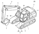
- FIG. 1 is a diagram illustrating the appearance of a work vehicle 101 based on the embodiment.
- a hydraulic excavator will be described as an example of the work vehicle 101 based on the embodiment.
- the work vehicle 101 mainly includes the traveling body 1, the turning body 3, and the work implement 4.
- the main body of the work vehicle 101 is composed of a traveling body 1 and a revolving body 3.
- a work machine 4 is attached to the main body.
- the traveling body 1 has a pair of left and right crawler belts.
- the turning body 3 is mounted so as to be turnable via the turning mechanism of the traveling body 1.
- the swivel body 3 has a cab 8 or the like.
- the work machine 4 is pivotally supported in the revolving structure 3 so as to be operable in the vertical direction, and performs work such as excavation of earth and sand.
- the work machine 4 includes a boom 5, an arm 6, and a bucket 7.
- the work machine 4 is provided at a position visually recognized from the cab 8 to the right front.
- the base of the boom 5 is movably connected to the revolving unit 3.
- the arm 6 is movably connected to the tip of the boom 5.
- the bucket 7 is movably connected to the tip of the arm 6.
- the bucket 7 is movable in the vertical direction with respect to the cab 8. Further, the bucket 7 is also movable in the front-rear direction with respect to the cab 8.
- the bucket 7 has a cutting edge 7A.
- the cab 8 has a windshield 2.
- the windshield 2 is fixed by a frame 9.
- the windshield 2 includes a windshield 2A and a windshield 2B below the windshield 2A.
- the windshield 2A is provided inside the opening frame 9A (inside the opening frame), and the windshield 2B is provided inside the lower opening frame 9B.
- the windshields 2 ⁇ / b> A and 2 ⁇ / b> B are provided separately according to the bent shape of the frame 9 in front of the cab 8.
- the display device 44 is attached in front of the driver's seat of the cab 8 of the work vehicle 101.
- the display device 44 includes a member (such as a film) that transmits external light incident on the cab 8 and a projector (projector).
- the image projected by the projector is displayed as a real image on a member (film or the like) that transmits external light.
- the display area of the display device 44 is provided in the opening frame 9 ⁇ / b> A on the front surface of the cab 8 of the work vehicle 101. The operator of the cab 8 can see the actual scene of the work site including the work machine 4 through the display area of the display device 44.
- the display device 44 displays information (work support information) for assisting the operation (work) of the work machine 4 by the operator, superimposed on the actual scene of the work site.
- the display device 44 functions as a head-up display that directly displays an image in the visual field of the operator.
- a member that transmits external light such as a film of the display device 44, is installed so as to be superimposed on the windshield 2A.
- the display device 44 has a display area up to the edge of the windshield 2A. Note that the size of the windshield 2A may be the same as the display area of the display device 44 or may be different.
- the display device 44 a configuration for displaying an image projected by a projector (projector) on a member (film or the like) that transmits external light incident on the cab 8 will be described.
- FIG. 2 is a block diagram showing a configuration of a control system provided in work vehicle 101 based on the embodiment.
- the work vehicle 101 includes an operation device 10, a work machine controller 20, a work machine drive device 30, and a display system 40.
- the operation device 10 includes operation members 11L and 11R, an operation detection unit 12, a travel operation member 13, and a travel operation detection unit 14.
- the operation members 11L and 11R are used by an operator to operate the work machine 4 and the swing body 3.
- the operation member 11 ⁇ / b> R is used for an operator to operate the boom 5 and the bucket 7.
- the operation member 11L is used for an operator to operate the swing body 3 and the arm 6.
- the operation detection unit 12 detects an operator's operation on the operation member 11L.
- the operation detection unit 12R detects an operator's operation on the operation member 11R.
- the traveling operation member 13 is used for an operator to operate the traveling of the work vehicle 101.
- the traveling operation detector 14 generates a pilot flow rate according to the operation content of the traveling operation member 13.
- the work vehicle 101 moves at a speed according to the pilot flow rate.
- the work machine controller 20 includes a storage unit 21 and a calculation unit 22.
- the storage unit 21 includes a memory such as a RAM (Random Access Memory) and a ROM (Read Only Memory).
- the calculation unit 22 is configured by a calculation processing device such as a CPU (Central Processing Unit).
- the work machine controller 20 mainly controls the operation of the work machine 4 and the turning of the revolving structure 3.
- the work machine controller 20 generates a control signal for operating the work machine 4 and the swing body 3 in accordance with the operation of the operation members 11L and 11R.
- the work machine controller 20 outputs the generated control signal to the work machine drive device 30.
- the work machine drive device 30 includes a proportional control valve 31.
- the proportional control valve 31 operates based on a control signal from the work machine controller 20.
- the proportional control valve 31 supplies hydraulic oil having a flow rate corresponding to the control signal to the hydraulic cylinder and the swing motor. Thereby, the working machine 4 operates and the revolving structure 3 turns.
- the display device 44 of the display system 40 displays various images such as work support information.
- the display system 40 includes a bucket position detection unit 41, a display control unit 43, and a display device 44.
- a predetermined reference position is set in advance as the viewpoint position of the operator.
- the bucket position detection unit 41 includes a bucket angle sensor 411, an arm angle sensor 412, and a boom angle sensor 413.
- the bucket angle sensor 411 detects a relative angle of the bucket 7 from a predetermined reference position.
- the arm angle sensor 412 detects a relative angle of the arm 6 from a predetermined reference position.
- the boom angle sensor 413 detects a relative angle of the boom 5 from a predetermined reference position.
- the bucket position detection unit 41 detects the position of the bucket 7 with respect to the work vehicle main body based on the detected information on the three relative angles. The position of the bucket 7 in the vehicle body coordinate system is detected. The bucket position detection unit 41 detects, for example, the position of the cutting edge 7 ⁇ / b> A of the bucket 7 as the position of the bucket 7.
- the display control unit 43 includes a display content control unit 430, a follow-up processing unit 434, and an image generation unit 433.
- the display control unit 43 causes the display device 44 to display work support information based on the detected position of the bucket 7.
- the image generation unit 433 generates an image to be displayed on the display device 44.
- the image generation unit 433 generates an image representing a vehicle speedometer, an engine tachometer, a fuel gauge, an oil temperature gauge, and the like. Furthermore, the image generation unit 433 generates an image representing the work support information.
- the image generation unit 433 is connected to a controller (not shown) that controls the power system of the work vehicle 101.
- the image generation unit 433 receives information detected by various sensors, information related to control contents by the controller, and the like.
- the image generation unit 433 generates an image to be displayed on the display device 44 based on the received information.
- the display content control unit 430 calculates the display position of the image on the display device 44, and displays the image at the calculated display position.
- the display content control unit 430 calculates the display position of the work support information on the display device 44 and displays the work support information at the calculated position. Further, the display content control unit 430 changes the display of the work support information according to the work situation.
- the follow-up processing unit 434 performs a process of moving and displaying at least one piece of work support information constituting the work support information displayed on the display device 44 following the movement of the bucket 7.
- Each functional block of the display control unit 43 is realized by an arithmetic processing device such as a CPU or a storage device such as a RAM and a ROM.
- FIG. 3 is a diagram for explaining the display contents of the work support information of the display device 44 based on the embodiment.
- FIG. 3 (A) shows work support information during rough excavation.
- the display content control unit 430 displays work support information in the display area of the display device 44. Specifically, two pieces of work support information 94 and 95 are displayed.
- the work support information 94 represents the design terrain direction and the distance between the design terrain and the cutting edge 7A. In FIG. 3A, 2.0 m is shown as the distance between the design topography and the cutting edge 7A.
- work support information 94 is displayed as information necessary for executing excavation work.
- the work support information 95 is a bar indicating the progress of work in the entire work process, and can be configured not to be displayed.
- Fig. 3 (B) shows work support information during finishing excavation.
- the display content control unit 430 displays work support information in the display area of the display device 44. Specifically, five pieces of work support information 91 to 95 are displayed.
- the display content control unit 430 determines whether the work status is during rough excavation or final excavation based on the distance between the cutting edge 7A of the bucket 7 and the design topography. Specifically, if it exceeds a predetermined value, it is determined that it is during rough excavation, and if it is less than the predetermined value, it is determined that it is during finish excavation.
- the display content control unit 430 displays work support information corresponding to the work situation based on the determination result.
- the distance between the cutting edge 7A of the bucket 7 and the design terrain is short, so various information is necessary to perform highly accurate excavation work, and more work support information is displayed than during rough excavation. To do.
- the display content control unit 430 displays each of the work support information 91 to 94 around the bucket 7.
- the display content control unit 430 may display the work support information 91 to 94 at a position above the blade edge 7A of the bucket 7.
- the display content control unit 430 performs the work support in the display device 44 so that the work support information 91 and 92 is visually recognized at the position on the left side of the bucket 7 when viewed from the cab 8.
- the display position of the information 91 and 92 is controlled.
- the display content control unit 430 controls the display positions of the work support information 93 and 94 on the display device 44 so that the work support information 93 and 94 is visually recognized at a position on the right side of the bucket 7 when viewed from the cab 8. To do.
- the work support information 91 represents a facing compass.
- the facing compass indicates whether the work vehicle 101 is in a state of facing the design terrain data. Further, when the facing compass is not in the facing state, the amount of deviation is represented by the rotation angle of the arrow inside the circle.
- the display control unit 43 displays the work support information 91 in a manner different from the manner shown in FIG. 3 such as changing the display color of the face-to-face compass. May be displayed.
- the work support information 92 represents a cross section (cross section) between the design topography and the cutting edge.
- the work support information 93 represents a light bar.
- the light bar is displayed during finish excavation. Like a light bar, the distance between the design terrain and the cutting edge 7A can be displayed as a graphic to improve the operator's information recognizability.
- the work support information 94 is indicated as 0.5 m as the design terrain direction and the distance between the design terrain and the cutting edge 7A.
- the display content control unit 430 determines whether the work status is during rough excavation or finish excavation based on the distance between the cutting edge 7A of the bucket 7 and the design topography, and according to the work status based on the determination result. Display work support information.
- the work support information 95 is a bar indicating the progress of work in the entire work process. As described with reference to FIG. 3A, during rough excavation, work support information (work support information 94) corresponding to the work situation is displayed around the bucket 7 so that a good view of the operator around the bucket 7 is secured. It becomes possible to do.
- work support information (work support information 91 to 94) corresponding to the work status is displayed around the bucket 7 so that highly accurate excavation work is performed. It is possible to improve the work efficiency.
- an operator working while visually observing the bucket can appropriately acquire work support information corresponding to the work situation based on the distance between the position of the bucket and the design landform, and further improve work efficiency. Can be achieved.
- the work support information displayed on the display device 44 is not limited to these.
- two work support information is displayed during rough excavation and five work support information is displayed during finish excavation.
- the present invention is not limited to this, and nothing is displayed during rough excavation. Instead, at least one piece of work support information may be displayed during finish excavation.
- the display content control unit 430 moves and displays the work support information 91 to 94 following the movement of the bucket 7 as shown in FIG.
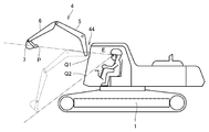
- FIG. 4 is a diagram for explaining a method for calculating the blade edge position of the bucket 7 on the display device 44.
- FIG. 4 shows the viewpoint position (reference position) E of the operator. Further, the bucket position detector 41 detects the position P of the cutting edge 7A of the bucket 7 in the vehicle body coordinate system. The display content control unit 430 calculates the position where the detected position P of the cutting edge 7A of the bucket 7 and the viewpoint position E of the operator intersect as the cutting edge position Q of the bucket 7 on the display device 44.
- FIG. 4 shows a case where the blade edge positions Q1, Q2 of the bucket 7 are calculated according to the state of the work machine 4.
- the follow-up processing unit 434 executes display processing that follows the movement of the bucket 7 for the work support information 91 to 94. Specifically, when the bucket 7 moves, the tracking processing unit 434 changes the display positions of the work support information 91 to 94 on the display device 44 to the movement of the bucket 7 based on the blade edge positions of the bucket 7 that are sequentially calculated. Perform processing to follow.
- the follow-up processing unit 434 causes the display positions of the work support information 91 to 94 to follow the movement of the bucket 7 so that the relative positional relationship with the bucket 7 is constant.
- the work support information 91 to 94 is arranged following the bucket 7 viewed by the operator. Thereby, the work efficiency can be further improved by reducing the visual movement of the operator.
- FIG. 5 is a flowchart for explaining the work support information display processing based on the embodiment.
- the display control unit 43 acquires the position of the bucket 7 and the position of the cutting edge 7A on the vehicle body coordinate system (step S2). Specifically, the display content control unit 430 acquires the positions of the bucket 7 and the cutting edge 7A of the bucket 7 in the vehicle body coordinate system according to the detection result of the bucket position detection unit 41.
- the display control unit 43 calculates the position of the bucket 7 and the position of the blade edge 7A on the global coordinate system (step S4). Specifically, the display content control unit 430 calculates the position of the bucket 7 and the position of the blade edge 7A on the global coordinate system based on information from various sensors.
- the display control unit 43 calculates the distance between the design landform and the cutting edge 7A of the bucket 7 (step S6). Specifically, the display content control unit 430 calculates the distance based on the data relating to the designed terrain provided in advance and the calculated position of the cutting edge 7A of the bucket 7.
- the display control unit 43 determines whether or not the distance between the design terrain and the cutting edge 7A of the bucket 7 is within a predetermined value (step S8). Specifically, the display content control unit 430 determines whether or not the distance between the predetermined design terrain data and the calculated blade edge 7A of the bucket 7 is within a predetermined value.
- the predetermined value may be set in advance or may be changed by an operator. When it is within the predetermined value, the work status is set to an appropriate value so that it is determined as finishing excavation, and when it is out of the predetermined value, the work status is determined as rough excavation.
- step S8 when the display control unit 43 determines that the distance between the design landform and the cutting edge 7A of the bucket 7 is not within the predetermined value (NO in step S8), the display control unit 43 displays the first work support information (step S8). S12). Specifically, when the display content control unit 430 determines that the distance between the design topography and the cutting edge 7A of the bucket 7 is not within a predetermined value, it determines that it is during rough excavation, and The work support information 94 and 95 described with reference to FIG.
- step S8 when the display control unit 43 determines in step S8 that the distance between the design topography and the position of the cutting edge 7A of the bucket 7 is within a predetermined value (YES in step S8), the second work support Information is displayed (step S12). Specifically, when the display content control unit 430 determines that the distance between the design terrain and the cutting edge 7A of the bucket 7 is within a predetermined value, the display content control unit 430 determines that it is during finishing excavation, and The work support information 91 to 95 described with reference to FIG.
- step S14 determines whether the work has been completed. If the display control unit 43 determines in step S14 that the work has been completed (YES in step S14), the display process ends (end). For example, when it is detected that the operator has performed an operation to stop the engine, it is determined that the work has been completed.
- step S14 determines in step S14 that the work has not been completed (NO in step S14)
- the process returns to step S2 and repeats the above processing.
- step S8 the method for determining whether or not the distance between the design terrain and the cutting edge 7A of the bucket 7 is within a predetermined value in step S8 has been described.
- this method is merely an example.
- a method for determining whether or not the distance between the design terrain and the blade edge 7A of the bucket 7 is a predetermined value and whether the distance between the design terrain and the blade edge 7A of the bucket 7 is smaller than a predetermined value as separate processes. It is also possible to adopt.
- the display control unit 43 can be changed to a method for determining whether or not the distance between the design landform and the cutting edge 7A of the bucket 7 is smaller than a predetermined value.
- the work vehicle 101 may include a display device having a configuration different from that of the display device 44. Specifically, the work vehicle 101 may include a combiner as a display device.
- FIG. 6 is a diagram illustrating another display device having a configuration different from the display device 44 of the embodiment.
- the display device 70 is provided in the cab 8 and includes a projector 71, a lens engineering system 72, and a combiner 73.
- Projector 71 is a projector.
- the lens engineering system 72 is installed between the projector 71 and the combiner 73.
- the lens engineering system 72 has a plurality of lenses. In the lens engineering system 72, some of the plurality of lenses are movable in the optical axis direction.
- the combiner 73 is installed on the windshield 2A.
- the combiner 73 may be installed on the windshield 2A and the windshield 2B.
- the combiner 73 is composed of a half mirror that reflects part of the light and transmits the remaining light.
- the combiner 73 reflects the image projected by the projector 71 to the operator side in the cab 8 and transmits light from outside the cab 8 into the cab 8.
- the operator can grasp the image projected on the combiner 73 as a virtual image that is displayed superimposed on the real scene in front of the cab 8.
- the display device 44 may display the inside of the opening frame 9B as a display area. That is, the cab 8 may be configured to include a transparent dual display. In this case, the display control unit 43 controls the display in the two display areas. Note that another display device may be provided for the display area of the opening frame 9B.
- the work support information can also be displayed in the display area of the lower display device. Therefore, when the bucket 7 moves downward, the display control unit 43 can cause the bucket 7 to follow the work support information to the lower side than in the case illustrated in FIG. 3 and the like.
- the configuration has been described in which the content of the work support information is changed based on whether or not the distance between the design terrain and the blade edge 7A of the bucket 7 is within a predetermined value. It is also possible to change the content of the work support information on the basis of it. Specifically, the content of the work support information may be changed according to work types such as flat ground work, dredging work, and slope shaping work. Judgment whether it is a flat work, a dredging work, or a slope shaping work may be made based on the design topography, or based on the construction plan data.
- work types such as flat ground work, dredging work, and slope shaping work. Judgment whether it is a flat work, a dredging work, or a slope shaping work may be made based on the design topography, or based on the construction plan data.
- the hydraulic excavator has been described as an example of the work vehicle, the present invention can also be applied to a backhoe loader and other work vehicles.
Landscapes
- Engineering & Computer Science (AREA)
- Mining & Mineral Resources (AREA)
- Civil Engineering (AREA)
- General Engineering & Computer Science (AREA)
- Structural Engineering (AREA)
- Mechanical Engineering (AREA)
- Chemical & Material Sciences (AREA)
- Combustion & Propulsion (AREA)
- Transportation (AREA)
- Component Parts Of Construction Machinery (AREA)
Abstract
Description
図1は、実施形態に基づく作業車両101の外観を説明する図である。
作業車両101の本体部は、走行体1と旋回体3とにより構成される。本体部には、作業機4が取り付けられている。走行体1は、左右1対の履帯を有している。旋回体3は、走行体1の旋回機構を介して旋回可能に装着される。旋回体3は、運転室8等を有する。
図2は、実施形態に基づく作業車両101が備える制御系の構成を表したブロック図である。
操作装置10は、操作部材11L、11Rと、操作検出部12と、走行操作部材13と、走行操作検出部14とを有する。
作業機コントローラ20は、記憶部21と、演算部22とを有している。記憶部21は、RAM(Random Access Memory)およびROM(Read Only Memory)等のメモリで構成される。演算部22は、CPU(Central Processing Unit)等の演算処理装置で構成される。
作業機駆動装置30は、比例制御弁31を有している。比例制御弁31は、作業機コントローラ20からの制御信号に基づいて動作する。比例制御弁31は、制御信号に応じた流量の作動油を、油圧シリンダおよび旋回モータに供給する。これにより、作業機4が動作し、旋回体3が旋回する。
表示システム40の表示装置44は、作業支援情報等の各種の画像を表示する。
図3は、実施形態に基づく表示装置44の作業支援情報の表示内容を説明する図である。
図3(A)で説明したように、荒掘削時には、バケット7周辺に当該作業状況に応じた作業支援情報(作業支援情報94)が表示されるためバケット7周辺のオペレータの良好な視界を確保することが可能になる。
図5は、実施形態に基づく作業支援情報の表示処理を説明するフロー図である。
ステップS14において、表示制御部43は、作業が終了したと判断した場合(ステップS14においてYES)には、表示処理を終了する(エンド)。たとえば、オペレータがエンジンを停止する動作をしたことを検知した場合には作業が終了したと判断する。
(e1.第1の変形例)
作業車両101は、表示装置44とは異なる構成の表示装置を備えていてもよい。具体的には、作業車両101は、表示装置としてコンバイナを備えていても良い。
上記においては、表示装置44が開口枠9A内の表示領域に表示する構成を例に挙げて説明したが、これに限定されるものではない。表示装置44が開口枠9B内も表示領域として表示する構成としても良い。すなわち、運転室8が透明のデュアルディスプレイを備える構成であってもよい。この場合、表示制御部43は、2つの表示領域における表示を制御することになる。なお、開口枠9Bの表示領域について別の表示装置を設けた構成とすることも可能である。
上記の構成において、設計地形とバケット7の刃先7Aとの距離が所定値以内であるか否かに基づいて作業支援情報の内容を変更する構成について説明したが、これに限られず他の条件に基づいて作業支援情報の内容を変更することも可能である。具体的には、平地作業、浚渫作業、法面整形作業等の作業種別に応じて作業支援情報の内容を変更するようにしても良い。平地作業、浚渫作業、あるいは法面整形作業かの判断は、設計地形に基づいて判断してもよく、施工計画データに基づいて判断するようにしてもよい。
Claims (5)
- バケットを有する作業機と、
前記作業機が取り付けられ、かつ運転室を有する本体部と、
前記バケットの位置を検出するバケット位置検出部と、
前記運転室に設けられ、作業現場の実景と重ね合わせて作業支援情報を表示する表示装置と、
前記バケット位置検出部で検出された前記バケットの位置と設計地形との距離に基づいて前記表示装置における前記作業支援情報の表示を変更する表示制御部とを備える、作業車両。 - 前記表示制御部は、前記バケットの位置と前記設計地形との距離が所定値以内である場合に前記表示装置における前記作業支援情報の表示を変更する、請求項1に記載の作業車両。
- 前記表示制御部は、前記バケットの移動に追従して移動する前記作業支援情報を表示する追従処理部をさらに含み、
前記表示制御部は、前記バケットの位置と前記設計地形との距離が所定値以内である場合には、前記表示装置における前記作業支援情報の表示数を増やす、請求項1または2に記載の作業車両。 - 前記表示制御部は、前記表示装置における前記作業支援情報を前記運転室内のオペレータから見て前記バケットの左側の位置または右側の位置の少なくとも一方に配置する、請求項1~3のいずれか1項に記載の作業車両。
- バケットを有する作業機と、前記運転室に設けられ、作業現場の実景と重ね合わせて作業支援情報を表示する表示装置とが設けられた作業車両の制御方法であって、
前記バケットの位置を検出するステップと、
検出された前記バケットの位置と設計地形との距離に基づいて前記表示装置における前記作業支援情報の表示を変更するステップとを備える、作業車両の制御方法。
Priority Applications (4)
| Application Number | Priority Date | Filing Date | Title |
|---|---|---|---|
| CN201680069077.1A CN108291388B (zh) | 2015-12-25 | 2016-11-29 | 作业车辆以及作业车辆的控制方法 |
| KR1020187014003A KR102119709B1 (ko) | 2015-12-25 | 2016-11-29 | 작업 차량 및 작업 차량의 제어 방법 |
| US16/060,111 US10954655B2 (en) | 2015-12-25 | 2016-11-29 | Work vehicle and method for controlling work vehicle |
| DE112016005230.8T DE112016005230T5 (de) | 2015-12-25 | 2016-11-29 | Arbeitsfahrzeug und Verfahren zum Steuern des Arbeitsfahrzeugs |
Applications Claiming Priority (2)
| Application Number | Priority Date | Filing Date | Title |
|---|---|---|---|
| JP2015-253702 | 2015-12-25 | ||
| JP2015253702A JP6666142B2 (ja) | 2015-12-25 | 2015-12-25 | 作業車両および作業車両の制御方法 |
Publications (1)
| Publication Number | Publication Date |
|---|---|
| WO2017110380A1 true WO2017110380A1 (ja) | 2017-06-29 |
Family
ID=59090078
Family Applications (1)
| Application Number | Title | Priority Date | Filing Date |
|---|---|---|---|
| PCT/JP2016/085345 WO2017110380A1 (ja) | 2015-12-25 | 2016-11-29 | 作業車両および作業車両の制御方法 |
Country Status (6)
| Country | Link |
|---|---|
| US (1) | US10954655B2 (ja) |
| JP (1) | JP6666142B2 (ja) |
| KR (1) | KR102119709B1 (ja) |
| CN (1) | CN108291388B (ja) |
| DE (1) | DE112016005230T5 (ja) |
| WO (1) | WO2017110380A1 (ja) |
Families Citing this family (4)
| Publication number | Priority date | Publication date | Assignee | Title |
|---|---|---|---|---|
| CN110520890B (zh) * | 2017-07-14 | 2023-12-22 | 株式会社小松制作所 | 工作信息发送装置、施工管理系统、工作信息发送方法及计算机可读记录介质 |
| JP7155516B2 (ja) * | 2017-12-20 | 2022-10-19 | コベルコ建機株式会社 | 建設機械 |
| JP7236826B2 (ja) * | 2018-07-31 | 2023-03-10 | 株式会社小松製作所 | 作業機械 |
| US11421400B2 (en) * | 2020-04-23 | 2022-08-23 | Deere & Company | Multiple mode operational system and method with object detection |
Citations (5)
| Publication number | Priority date | Publication date | Assignee | Title |
|---|---|---|---|---|
| JPH01312129A (ja) * | 1988-06-13 | 1989-12-15 | Komatsu Ltd | 腕式作業機のモニタ装置 |
| JP2004068433A (ja) * | 2002-08-07 | 2004-03-04 | Hitachi Constr Mach Co Ltd | 掘削機械の表示システム及びそのプログラム |
| JP2013113044A (ja) * | 2011-11-30 | 2013-06-10 | Sumitomo (Shi) Construction Machinery Co Ltd | 建設機械用モニタシステム |
| JP2014129676A (ja) * | 2012-12-28 | 2014-07-10 | Komatsu Ltd | 建設機械の表示システムおよびその制御方法 |
| JP2014205955A (ja) * | 2013-04-10 | 2014-10-30 | 株式会社小松製作所 | 掘削機械の施工管理装置、油圧ショベルの施工管理装置、掘削機械及び施工管理システム |
Family Cites Families (14)
| Publication number | Priority date | Publication date | Assignee | Title |
|---|---|---|---|---|
| JP2000291048A (ja) * | 1999-04-01 | 2000-10-17 | Tokai Rika Co Ltd | パワーショベル |
| JP2001032331A (ja) * | 1999-07-19 | 2001-02-06 | Hitachi Constr Mach Co Ltd | 建設機械の領域制限制御装置および領域制限制御方法 |
| US7113105B2 (en) * | 2003-08-28 | 2006-09-26 | Caterpillar Inc. | Work machine display system |
| JP3902168B2 (ja) * | 2003-09-04 | 2007-04-04 | 日立建機株式会社 | 建設機械の診断情報表示システム |
| JP4079113B2 (ja) * | 2004-04-19 | 2008-04-23 | 日立建機株式会社 | 建設機械の表示装置 |
| US8817238B2 (en) * | 2007-10-26 | 2014-08-26 | Deere & Company | Three dimensional feature location from an excavator |
| JP5113586B2 (ja) | 2008-03-28 | 2013-01-09 | 株式会社小松製作所 | 作業車両 |
| EP2586918A4 (en) * | 2010-06-23 | 2014-10-29 | Doosan Infracore Co Ltd | APPARATUS AND METHOD FOR CONTROLLING A WORKING TRACK OF A CONSTRUCTION MACHINE |
| JP5586568B2 (ja) | 2011-11-15 | 2014-09-10 | 株式会社小松製作所 | 建設機械の情報表示装置、建設機械の情報表示方法及び建設機械の情報表示用コンピュータプログラム |
| US20130255977A1 (en) * | 2012-03-27 | 2013-10-03 | Caterpillar, Inc. | Control for Motor Grader Curb Operations |
| JP5480941B2 (ja) * | 2012-08-02 | 2014-04-23 | 株式会社小松製作所 | 掘削機械の表示システム及びその制御方法。 |
| JP5624101B2 (ja) * | 2012-10-05 | 2014-11-12 | 株式会社小松製作所 | 掘削機械の表示システム、掘削機械及び掘削機械の表示用コンピュータプログラム |
| JP5476450B1 (ja) * | 2012-11-19 | 2014-04-23 | 株式会社小松製作所 | 掘削機械の表示システム及び掘削機械 |
| JP5465345B1 (ja) | 2013-01-18 | 2014-04-09 | 株式会社小松製作所 | 油圧ショベル |
-
2015
- 2015-12-25 JP JP2015253702A patent/JP6666142B2/ja active Active
-
2016
- 2016-11-29 DE DE112016005230.8T patent/DE112016005230T5/de active Pending
- 2016-11-29 WO PCT/JP2016/085345 patent/WO2017110380A1/ja active Application Filing
- 2016-11-29 KR KR1020187014003A patent/KR102119709B1/ko active IP Right Grant
- 2016-11-29 US US16/060,111 patent/US10954655B2/en active Active
- 2016-11-29 CN CN201680069077.1A patent/CN108291388B/zh active Active
Patent Citations (5)
| Publication number | Priority date | Publication date | Assignee | Title |
|---|---|---|---|---|
| JPH01312129A (ja) * | 1988-06-13 | 1989-12-15 | Komatsu Ltd | 腕式作業機のモニタ装置 |
| JP2004068433A (ja) * | 2002-08-07 | 2004-03-04 | Hitachi Constr Mach Co Ltd | 掘削機械の表示システム及びそのプログラム |
| JP2013113044A (ja) * | 2011-11-30 | 2013-06-10 | Sumitomo (Shi) Construction Machinery Co Ltd | 建設機械用モニタシステム |
| JP2014129676A (ja) * | 2012-12-28 | 2014-07-10 | Komatsu Ltd | 建設機械の表示システムおよびその制御方法 |
| JP2014205955A (ja) * | 2013-04-10 | 2014-10-30 | 株式会社小松製作所 | 掘削機械の施工管理装置、油圧ショベルの施工管理装置、掘削機械及び施工管理システム |
Also Published As
| Publication number | Publication date |
|---|---|
| CN108291388B (zh) | 2021-06-25 |
| KR102119709B1 (ko) | 2020-06-05 |
| US20180355586A1 (en) | 2018-12-13 |
| KR20180067673A (ko) | 2018-06-20 |
| US10954655B2 (en) | 2021-03-23 |
| DE112016005230T5 (de) | 2018-07-26 |
| JP2017115489A (ja) | 2017-06-29 |
| CN108291388A (zh) | 2018-07-17 |
| JP6666142B2 (ja) | 2020-03-13 |
Similar Documents
| Publication | Publication Date | Title |
|---|---|---|
| KR101815268B1 (ko) | 건설 기계의 표시 시스템 및 그 제어 방법 | |
| US11105072B2 (en) | Work vehicle and display control method | |
| CN108779616B (zh) | 机动平路机的控制方法、机动平路机以及机动平路机的作业管理系统 | |
| KR102123480B1 (ko) | 작업 차량 및 표시 제어 방법 | |
| WO2017110380A1 (ja) | 作業車両および作業車両の制御方法 | |
| JP6707344B2 (ja) | 作業車両および作業車両の制御方法 | |
| JP6454383B2 (ja) | 建設機械の表示システムおよびその制御方法 | |
| WO2017110379A1 (ja) | 作業車両および作業車両の制御方法 | |
| JP6823036B2 (ja) | 建設機械の表示システムおよびその制御方法 | |
| JP7168697B2 (ja) | 建設機械の表示システムおよびその制御方法 | |
| US20180363273A1 (en) | Work vehicle |
Legal Events
| Date | Code | Title | Description |
|---|---|---|---|
| 121 | Ep: the epo has been informed by wipo that ep was designated in this application |
Ref document number: 16878274 Country of ref document: EP Kind code of ref document: A1 |
|
| ENP | Entry into the national phase |
Ref document number: 20187014003 Country of ref document: KR Kind code of ref document: A |
|
| WWE | Wipo information: entry into national phase |
Ref document number: 112016005230 Country of ref document: DE |
|
| 122 | Ep: pct application non-entry in european phase |
Ref document number: 16878274 Country of ref document: EP Kind code of ref document: A1 |