WO2017110330A1 - シャフトの連結構造 - Google Patents
シャフトの連結構造 Download PDFInfo
- Publication number
- WO2017110330A1 WO2017110330A1 PCT/JP2016/084283 JP2016084283W WO2017110330A1 WO 2017110330 A1 WO2017110330 A1 WO 2017110330A1 JP 2016084283 W JP2016084283 W JP 2016084283W WO 2017110330 A1 WO2017110330 A1 WO 2017110330A1
- Authority
- WO
- WIPO (PCT)
- Prior art keywords
- coupling
- shaft
- serration
- slit
- shape
- Prior art date
- Legal status (The legal status is an assumption and is not a legal conclusion. Google has not performed a legal analysis and makes no representation as to the accuracy of the status listed.)
- Ceased
Links
Images



Classifications
-
- F—MECHANICAL ENGINEERING; LIGHTING; HEATING; WEAPONS; BLASTING
- F16—ENGINEERING ELEMENTS AND UNITS; GENERAL MEASURES FOR PRODUCING AND MAINTAINING EFFECTIVE FUNCTIONING OF MACHINES OR INSTALLATIONS; THERMAL INSULATION IN GENERAL
- F16D—COUPLINGS FOR TRANSMITTING ROTATION; CLUTCHES; BRAKES
- F16D3/00—Yielding couplings, i.e. with means permitting movement between the connected parts during the drive
- F16D3/50—Yielding couplings, i.e. with means permitting movement between the connected parts during the drive with the coupling parts connected by one or more intermediate members
- F16D3/72—Yielding couplings, i.e. with means permitting movement between the connected parts during the drive with the coupling parts connected by one or more intermediate members with axially-spaced attachments to the coupling parts
- F16D3/74—Yielding couplings, i.e. with means permitting movement between the connected parts during the drive with the coupling parts connected by one or more intermediate members with axially-spaced attachments to the coupling parts the intermediate member or members being made of rubber or other rubber-like flexible material
-
- F—MECHANICAL ENGINEERING; LIGHTING; HEATING; WEAPONS; BLASTING
- F16—ENGINEERING ELEMENTS AND UNITS; GENERAL MEASURES FOR PRODUCING AND MAINTAINING EFFECTIVE FUNCTIONING OF MACHINES OR INSTALLATIONS; THERMAL INSULATION IN GENERAL
- F16D—COUPLINGS FOR TRANSMITTING ROTATION; CLUTCHES; BRAKES
- F16D3/00—Yielding couplings, i.e. with means permitting movement between the connected parts during the drive
- F16D3/50—Yielding couplings, i.e. with means permitting movement between the connected parts during the drive with the coupling parts connected by one or more intermediate members
- F16D3/54—Couplings comprising a chain or strip surrounding two wheels arranged side by side and provided with teeth or the equivalent
Definitions
- This disclosure relates to a shaft connection structure that stabilizes torque characteristics.
- a coupling for power transmission is used to connect a rotating shaft of a driving source such as a motor and a driven shaft such as a speed reducer (for example, a patent) Reference 1).
- the width of the slit formed in such a coupling corresponds to the tooth width of the serration formed on the rotating shaft or the driven shaft (shaft).
- ⁇ A coupling whose slit width corresponds to the serration width can move freely in the axial direction, and the coupling between the coupling and the shaft is not stable. Therefore, when connecting a shaft using such a coupling, there exists a problem that a torque characteristic is not stabilized.
- An object of the present disclosure is to provide a shaft connection structure that stabilizes torque characteristics.
- the shaft coupling structure of the present disclosure has a cylindrical coupling having an axially extending slit on the inner wall surface and a serration inserted into the slit on the outer peripheral surface, and is inserted from both ends of the coupling toward the inside.
- a shaft connection structure comprising: a pair of shafts, wherein at least one of a serration of the shaft and a slit of the coupling has a shape shown in A or B below.
- B A shape in which the width of at least one slit becomes narrower from the end of the coupling toward the center.
- torque characteristics can be stabilized.
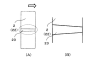
- FIG. 3A is a plan view of the shaft shown in FIG. 1 viewed from the direction of arrow B
- FIG. 3B is an enlarged view of a portion surrounded by a broken line in FIG. 4A is a side view seen from the direction of arrow C in FIG. 1
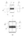
- FIG. 4B is an explanatory view showing a state after the shaft is inserted into the coupling in FIG. 4A.
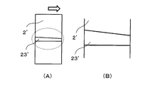
- FIG. 5A is a plan view for explaining another shape of the serration
- FIG. 5B is an enlarged view of a portion surrounded by a broken line in FIG.
- the shaft connection structure shown in FIG. 1 includes a coupling 1 and a shaft 2.
- the coupling 1 has a two-layer structure.
- the outer layer is formed of a casing 11 and the inner layer is formed of a sliding material 12.
- the coupling 1 is cylindrical and has a slit 13 extending in the axial direction on the inner wall surface.
- the material of the casing 11 is not particularly limited, and examples thereof include metals such as iron, steel, stainless steel, and aluminum. As shown in FIG. 1, the casing 11 may be provided with irregularities on the surface according to the shape of the slit 13 or may be a smooth surface.
- size of the casing 11 is not specifically limited, It sets suitably according to the use for which the connection structure of the shaft which concerns on one Embodiment is employ
- the sliding member 12 is formed of, for example, an elastomer and a fiber member, and is obtained by impregnating an elastomer into a fiber member such as a canvas.
- the elastomer is not particularly limited.
- Examples of fibers forming the fiber member of the sliding member 12 include cotton, silk, hemp, aramid fiber, nylon, urethane, polyester, acetate, rayon, and the like.
- Examples of the canvas include woven fabrics, knitted fabrics, and non-woven fabrics.
- the sliding member 12 is attached to the inner peripheral surface of the casing 11.
- the method for attaching the sliding material 12 to the casing 11 is not particularly limited, and examples thereof include a method for attaching using the adhesive.
- the adhesive include an acrylic resin adhesive, an olefin resin adhesive, a urethane resin adhesive, and an epoxy resin adhesive.
- the sliding member 12 forms the innermost layer of the coupling 1, that is, the inner wall surface of the coupling 1 so as to be in contact with the shaft 2.
- a slit 13 extending in the axial direction is formed on the inner wall surface.
- eight slits 13 are formed on the inner wall surface of the coupling 1.
- the slit 13 is formed on the inner wall surface of the coupling 1 with a constant width from one end to the other end.
- the coupling 1 Since the coupling 1 has the sliding member 12 formed of such a rubber and a fiber member, it is only necessary to insert a shaft having a serration formed into a slope shape described later into the coupling 1. Pre-deformation (pre-load) can be applied. By the predeformation, free movement of the coupling 1 in the axial direction can be suppressed, and the coupling 1 can be fixed at a fixed position. Furthermore, by using the sliding member 12 formed of rubber and a fiber member, generation of noise during use is suppressed.
- the shaft 2 will be described by taking the rotating shaft 21 and the driven shaft 22 as examples.
- the shaft 2 has a serration 23 on the outer peripheral surface. Eight serrations 23 are formed on each of the rotating shaft 21 and the driven shaft 22 so as to correspond to the slits 13 of the coupling 1.
- Serration 23 is not formed with a certain size (width). As shown in FIGS. 3 (A) and 3 (B), the serration 23 is formed with a narrower width in the direction of entry into the coupling 1 (the arrow direction in FIG. 3 (A)) and has a tapered shape. Yes.
- the side surface of the serration 23 is preferably inclined at about 2 to 7 degrees with respect to the axial direction.
- the serrations 23 formed on the rotary shaft 21 and the driven shaft 22 at least one serration 23 only needs to be tapered in each of the rotary shaft 21 and the driven shaft 22. However, in order to more securely fix the coupling 1, it is preferable that all the serrations 23 have a tapered shape.
- the width of the narrowest part of the serration 23 corresponds to the width of the slit 13 of the coupling 1.
- the sliding member 12 of the coupling 1 is formed of an elastomer and a fiber member. Therefore, as shown in FIGS. 4A and 4B, when the serration 23 of the shaft 2 is inserted into the slit 13 of the coupling 1, the sliding member 12 can be pre-deformed. Therefore, as shown in FIG. 4B, since the serrations 23 inserted from both ends of the coupling 1 are fixed at a fixed position, the coupling 1 can also be fixed and restrained from moving.
- the shaft coupling structure according to the above-described embodiment can be suitably employed in, for example, various industrial machines, automobile power transmission devices (for example, machine tools such as NC lathes, electric power steering devices, etc.).
- the shaft connection structure according to the present disclosure is not limited to the above-described embodiment.
- the shape of the serration formed on the shaft is not particularly limited as long as it is a shape that is fixed at a fixed position and can restrain the movement of the coupling when inserted from both ends of the coupling.
- Examples of such serrations include serrations having shapes as shown in FIGS.
- FIG. 5 (A) is a plan view for explaining another shape of the serration
- FIG. 5 (B) is an enlarged view of a portion surrounded by a broken line in FIG. 5 (A).
- the serration 23 described above has a shape in which both side surfaces are inclined inwardly toward the direction of entry into the coupling 1 (the direction of the arrow in FIG. 3).
- the serration 23 ′ shown in FIG. 5 (A) has a shape in which only one side surface is inclined and narrowed inward in the direction of entering the coupling 1 (the arrow direction in FIG. 5 (A)). ing.
- FIG. 6 is a side view for explaining another shape of the serration.
- a serration 23 ′′ shown in FIG. 6 has a shape in which the upper surface, not the side surface, is inclined downward and narrows in the direction of entering the coupling 1 (the arrow direction in FIG. 6).
- the serration 23 ′′ shown in FIG. 6 may be a serration having a shape in which at least one side surface is inclined inward as shown in FIG. 3 or FIG. 5.
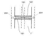
- the slit 131 of the coupling 1 ′ is formed in a tapered shape. That is, the width of the slit 131 is narrowed from the end of the coupling 1 ′ toward the center.
- the tip of the serration 231 of the shaft is near the center of the slit 131 and the wall surface (sliding material 121) of the slit 131. Contact. For this reason, the coupling 1 ′ cannot be moved to the left or right, and can be restrained.
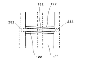
- both the slit 132 of the coupling 1 ′′ and the serration 232 of the shaft are formed in a tapered shape. Even when both the slit 132 and the serration 232 are formed in a taper shape, when the shaft is inserted from both ends of the coupling, the tip of the shaft serration 232 is located near the center of the slit 132 (sliding surface). In contact with the moving material 122). Therefore, the coupling 1 ′′ cannot move to the left or right, and can be restrained.
- the coupling 1 in which the eight slits 13 are formed is used.
- the number of slits is not particularly limited, and it is sufficient that at least one slit is formed in the coupling, and preferably about 4 to 10 are formed.
- the number of serrations formed on the shaft is appropriately set according to the number of slits formed on the coupling.
- this indication is not limited to this, and various change and improvement are possible if it is in the range as described in a claim.
Landscapes
- Engineering & Computer Science (AREA)
- General Engineering & Computer Science (AREA)
- Mechanical Engineering (AREA)
- Shafts, Cranks, Connecting Bars, And Related Bearings (AREA)
Abstract
本開示に係るシャフトの連結構造は、内壁面に軸方向に延びるスリットを有する筒状のカップリングと、スリットに嵌入されるセレーションを外周面に有し、カップリングの両端から内部に向けて挿入される一対のシャフトとを備え、シャフトのセレーションおよびカップリングのスリットの少なくとも一方が、下記AまたはBに示す形状を有していることを特徴とするシャフトの連結構造。 A一対のシャフトにおいて、各シャフトの少なくとも1つのセレーションの幅が、カップリングへの進入方向に向けて狭くなる形状。 B少なくとも1つのスリットの幅が、カップリングの端部から中央部に向けて狭くなる形状。
Description
本開示は、トルク特性を安定化させるシャフトの連結構造に関する。
各種産業用機械や自動車用の動力伝達装置などにおいて、モーターのような駆動源の回転軸と減速機などの従動軸との接続には、動力伝達用のカップリングが使用される(例えば、特許文献1)。このようなカップリングに形成されるスリットの幅は、回転軸や従動軸(シャフト)に形成されるセレーションの歯幅に対応している。
このようなスリットの幅がセレーションの幅に対応したカップリングは、軸方向に自由に移動することができ、カップリングとシャフトとの取り合いが安定しない。そのため、このようなカップリングを用いてシャフトを接続する場合、トルク特性が安定しないという問題がある。
本開示の課題は、トルク特性を安定化させるシャフトの連結構造を提供することである。
本開示のシャフトの連結構造は、内壁面に軸方向に延びるスリットを有する筒状のカップリングと、スリットに嵌入されるセレーションを外周面に有し、カップリングの両端から内部に向けて挿入される一対のシャフトとを備えるシャフトの連結構造であって、シャフトのセレーションおよびカップリングのスリットの少なくとも一方が、下記AまたはBに示す形状を有していることを特徴とするシャフトの連結構造。
A一対のシャフトにおいて、各シャフトの少なくとも1つのセレーションの幅が、カップリングへの進入方向に向けて狭くなる形状。
B少なくとも1つのスリットの幅が、カップリングの端部から中央部に向けて狭くなる形状。
A一対のシャフトにおいて、各シャフトの少なくとも1つのセレーションの幅が、カップリングへの進入方向に向けて狭くなる形状。
B少なくとも1つのスリットの幅が、カップリングの端部から中央部に向けて狭くなる形状。
本開示によれば、トルク特性を安定化させることができる。
以下、一実施形態に係るシャフトの連結構造を図1~4に基づいて説明する。図1に示すシャフトの連結構造は、カップリング1とシャフト2とを備える。カップリング1は、図2に示すように2層構造を有しており、外層がケーシング11で形成され、内層が摺動材12で形成されている。カップリング1は筒状で、内壁面に軸方向に延びるスリット13を有している。
ケーシング11の材質は特に限定されず、例えば、鉄、鋼、ステンレス鋼、アルミニウムなどの金属などが挙げられる。ケーシング11は、図1に示すように、スリット13の形状に応じて凹凸を表面に設けてもよく、滑らかな表面であってもよい。ケーシング11の大きさは特に限定されず、一実施形態に係るシャフトの連結構造が採用される用途に応じて適宜設定される。ケーシング11はカップリング1の最外層を形成しているため、ケーシング11の大きさがカップリング1の大きさとなる。
摺動材12は、例えば、エラストマーと繊維部材とで形成されており、帆布などの繊維部材にエラストマーを含浸させることによって得られる。エラストマーは特に限定されず、例えば、ニトリルゴム、クロロプレンゴム、クロロスルホン化ポリエチレン、ポリブタジエンゴム、天然ゴム、エチレンプロピレンゴム(EPM)、エチレンプロピレンジエンゴム(EPDM)、水素化ニトリルゴム(H-NBR)、ミラブルウレタン、アクリルゴム、シリコンゴム、フッ素ゴム、カルボキシル化ニトリルゴム、熱可塑性エラストマーなどが挙げられる。これらのゴムは、1種のみを用いてもよく、2種以上を混合して用いてもよい。
摺動材12の繊維部材を形成している繊維としては、例えば、木綿、絹、麻、アラミド繊維、ナイロン、ウレタン、ポリエステル、アセテート、レーヨンなどが挙げられる。また、帆布としては、例えば、織物や編布、不織布などが挙げられる。
摺動材12は、ケーシング11の内周面に取り付けられている。摺動材12をケーシング11取り付ける方法は特に限定されず、例えば接着剤を用いて取り付ける方法が挙げられる。接着剤としては、例えば、アクリル樹脂系接着剤、オレフィン樹脂系接着剤、ウレタン樹脂系接着剤、エポキシ樹脂系接着剤などが挙げられる。
摺動材12は、シャフト2と接触し得るようにカップリング1の最内層、すなわちカップリング1の内壁面を形成している。この内壁面には、軸方向に延びるスリット13が形成されている。一実施形態に係るシャフトの連結構造では、カップリング1の内壁面に8本のスリット13が形成されている。スリット13は、カップリング1の内壁面に、一定の幅で一方の端部から他方の端部まで形成されている。
カップリング1が、このようなゴムと繊維部材とで形成された摺動材12を有していることによって、後述する斜面状に形成されたセレーションを有するシャフトをカップリング1に挿入するだけで、予変形(予圧)を与えることができる。その予変形によって、カップリング1の軸方向の自由な移動を抑制することができ、カップリング1を定位置で固定することができる。さらに、ゴムと繊維部材とで形成された摺動材12を用いることによって、使用時に騒音の発生も抑制される。
次に、シャフト2を、回転軸21および従動軸22を例に挙げて説明する。シャフト2は、外周面にセレーション23を有している。セレーション23は、カップリング1のスリット13に対応するように、回転軸21および従動軸22のそれぞれに8本形成されている。
セレーション23は一定の大きさ(幅)で形成されていない。図3(A)および(B)に示すように、セレーション23は、カップリング1への進入方向(図3(A)の矢印方向)に向けて幅が狭く形成され、テーパー状を有している。セレーション23の側面は、軸方向に対して、好ましくは約2~7度傾斜している。回転軸21および従動軸22に形成されたセレーション23は、回転軸21および従動軸22のそれぞれにおいて、少なくとも1つのセレーション23がテーパー状を有していればよい。しかし、カップリング1をより確実に固定するには、すべてのセレーション23がテーパー状を有していることが好ましい。
セレーション23の最も狭い部分の幅が、カップリング1のスリット13の幅に対応している。また、上述のように、カップリング1の摺動材12はエラストマーと繊維部材とで形成されている。そのため、図4(A)および(B)に示すように、カップリング1のスリット13にシャフト2のセレーション23を挿入すると、摺動材12に予変形を与えることができる。したがって、図4(B)に示すように、カップリング1の両端から挿入されたセレーション23は、一定の位置で固定されるため、カップリング1も固定されて移動を拘束することができる。
その結果、上述の一実施形態に係るシャフトの連結構造を採用すれば、回転軸21の動力を、安定したトルク特性で従動軸22に伝えることが可能となる。この一実施形態に係るシャフトの連結構造は、例えば各種産業用機械や、自動車用の動力伝達装置(例えば、NC旋盤などの工作機械、電動パワーステアリング装置など)などにおいて好適に採用され得る。
本開示に係るシャフトの連結構造は、上述の一実施形態に限定されない。例えば、シャフトに形成されるセレーションの形状は、カップリングの両端から挿入した際に、一定の位置で固定され、カップリングの移動を拘束し得る形状であれば特に限定されない。このようなセレーションとしては、例えば図5および6に示すような形状のセレーションが挙げられる。
図5(A)はセレーションの別の形状を説明するための平面図であり、図5(B)は図5(A)の破線で囲んだ部分の拡大図である。上述のセレーション23は、カップリング1への進入方向(図3の矢印方向)に向けて両側面が内側に傾き狭くなる形状を有している。これに対し、図5(A)に示すセレーション23’は、カップリング1への進入方向(図5(A)の矢印方向)に向けて一方の側面のみが内側に傾き狭くなる形状を有している。
図6はセレーションのさらに別の形状を説明するための側面図である。図6に示すセレーション23’’は、側面ではなく上面がカップリング1への進入方向(図6の矢印方向)に向けて下方に傾き狭くなる形状を有している。
図5および図6に示すようなセレーション23’、23’’であっても、カップリングの両端から挿入すると一定の位置で固定される。したがって、カップリングを固定することができ、移動を拘束することができる。図6に示すセレーション23’’において、図3または図5に示すように、少なくとも一方の側面を内側に傾けた形状を有するセレーションであってもよい。
図7に示す別の実施形態では、カップリング1’のスリット131がテーパー状に形成されている。すなわち、スリット131の幅が、カップリング1’の端部から中央部に向けて狭くなっている。スリット131がこのような形状を有している場合、シャフトをカップリングの両端から挿入した際に、シャフトのセレーション231の先端がスリット131の中央付近でスリット131の壁面(摺動材121)と接触する。そのため、カップリング1’は左右のいずれにも移動することができず、拘束することができる。
図8に示すさらに別の実施形態では、カップリング1’’のスリット132とシャフトのセレーション232との両方がテーパー状に形成されている。スリット132とセレーション232との両方がテーパー状に形成されている場合も、シャフトをカップリングの両端から挿入した際に、シャフトのセレーション232の先端がスリット132の中央付近でスリット132の壁面(摺動材122)と接触する。そのため、カップリング1’’は左右のいずれにも移動することができず、拘束することができる。
上述の一実施形態に係るシャフトの連結構造では、8本のスリット13が形成されたカップリング1が使用されている。スリットの数は特に限定されず、カップリングに少なくとも1本形成されていればよく、好ましくは4~10本程度形成される。シャフトに形成されるセレーションの数は、カップリングに形成されるスリットの数に応じて適宜設定される。
以上、本開示の一実施形態について説明したが、本開示はこれに限定されるものではなく、請求の範囲に記載の範囲内であれば種々の変更や改良は可能である。
1、1’、1’’ カップリング
11 ケーシング
12 摺動材
13 スリット
2、2’、2’’ シャフト
21 回転軸
22 従動軸
23、23’、23’’ セレーション
121 摺動材
131 スリット
231セレーション
122 摺動材
132 スリット
232 セレーション
11 ケーシング
12 摺動材
13 スリット
2、2’、2’’ シャフト
21 回転軸
22 従動軸
23、23’、23’’ セレーション
121 摺動材
131 スリット
231セレーション
122 摺動材
132 スリット
232 セレーション
Claims (4)
- 内壁面に軸方向に延びるスリットを有する筒状のカップリングと、
前記スリットに嵌入されるセレーションを外周面に有し、前記カップリングの両端から内部に向けて挿入される一対のシャフトと、
を備えるシャフトの連結構造であって、
前記シャフトのセレーションおよび前記カップリングのスリットの少なくとも一方が、下記AまたはBに示す形状を有していることを特徴とするシャフトの連結構造。
A前記一対のシャフトにおいて、各シャフトの少なくとも1つの前記セレーションの幅が、前記カップリングへの進入方向に向けて狭くなる形状。
B少なくとも1つの前記スリットの幅が、前記カップリングの端部から中央部に向けて狭くなる形状。 - 前記カップリングが少なくとも2層構造を有しており、最外層がケーシングで形成されており、最内層が繊維部材にエラストマーを含浸させた摺動材で形成されている請求項1に記載のシャフトの連結構造。
- 前記カップリングにスリットが4~10本形成されている請求項1または2に記載のシャフトの連結構造。
- 前記セレーションの側面は、前記カップリングの軸方向に対して、約2~7度傾斜している請求項1~3のいずれかに記載のシャフトの連結構造。
Applications Claiming Priority (2)
| Application Number | Priority Date | Filing Date | Title |
|---|---|---|---|
| JP2015253588A JP2017116021A (ja) | 2015-12-25 | 2015-12-25 | シャフトの連結構造 |
| JP2015-253588 | 2015-12-25 |
Publications (1)
| Publication Number | Publication Date |
|---|---|
| WO2017110330A1 true WO2017110330A1 (ja) | 2017-06-29 |
Family
ID=59090556
Family Applications (1)
| Application Number | Title | Priority Date | Filing Date |
|---|---|---|---|
| PCT/JP2016/084283 Ceased WO2017110330A1 (ja) | 2015-12-25 | 2016-11-18 | シャフトの連結構造 |
Country Status (3)
| Country | Link |
|---|---|
| JP (1) | JP2017116021A (ja) |
| TW (1) | TW201727092A (ja) |
| WO (1) | WO2017110330A1 (ja) |
Cited By (2)
| Publication number | Priority date | Publication date | Assignee | Title |
|---|---|---|---|---|
| WO2019176871A1 (ja) * | 2018-03-12 | 2019-09-19 | 日本精工株式会社 | トルク伝達用継手および電動式パワーステアリング装置 |
| CN111844327A (zh) * | 2019-04-26 | 2020-10-30 | 四川盘流科技有限公司 | 一种循环托盘的组装方法 |
Citations (3)
| Publication number | Priority date | Publication date | Assignee | Title |
|---|---|---|---|---|
| JPH11270571A (ja) * | 1998-03-25 | 1999-10-05 | Mitsubishi Heavy Ind Ltd | バックラッシ量調整装置 |
| JP2006017295A (ja) * | 2004-05-31 | 2006-01-19 | Gates Unitta Asia Co | カップリング |
| JP2014035040A (ja) * | 2012-08-09 | 2014-02-24 | Ricoh Co Ltd | 駆動伝達装置、画像形成装置 |
-
2015
- 2015-12-25 JP JP2015253588A patent/JP2017116021A/ja active Pending
-
2016
- 2016-11-18 WO PCT/JP2016/084283 patent/WO2017110330A1/ja not_active Ceased
- 2016-12-05 TW TW105140081A patent/TW201727092A/zh unknown
Patent Citations (3)
| Publication number | Priority date | Publication date | Assignee | Title |
|---|---|---|---|---|
| JPH11270571A (ja) * | 1998-03-25 | 1999-10-05 | Mitsubishi Heavy Ind Ltd | バックラッシ量調整装置 |
| JP2006017295A (ja) * | 2004-05-31 | 2006-01-19 | Gates Unitta Asia Co | カップリング |
| JP2014035040A (ja) * | 2012-08-09 | 2014-02-24 | Ricoh Co Ltd | 駆動伝達装置、画像形成装置 |
Cited By (2)
| Publication number | Priority date | Publication date | Assignee | Title |
|---|---|---|---|---|
| WO2019176871A1 (ja) * | 2018-03-12 | 2019-09-19 | 日本精工株式会社 | トルク伝達用継手および電動式パワーステアリング装置 |
| CN111844327A (zh) * | 2019-04-26 | 2020-10-30 | 四川盘流科技有限公司 | 一种循环托盘的组装方法 |
Also Published As
| Publication number | Publication date |
|---|---|
| JP2017116021A (ja) | 2017-06-29 |
| TW201727092A (zh) | 2017-08-01 |
Similar Documents
| Publication | Publication Date | Title |
|---|---|---|
| KR102453328B1 (ko) | 전동식 동력 보조 조향장치 | |
| WO2017110330A1 (ja) | シャフトの連結構造 | |
| KR101262130B1 (ko) | 유성기어장치 | |
| TW200616855A (en) | A friction welding equipment for a packaging machine | |
| EP3176452A1 (en) | Structure for shaft, male member, and female member | |
| EP3283793A1 (de) | Getriebe, aufweisend eine welle, ein flanschteil und ein gehäuseteil | |
| JP6170425B2 (ja) | 摩擦ダンパー | |
| US20190249751A1 (en) | Speed reducer, motor unit, and cleaning robot | |
| KR101616075B1 (ko) | 모터용 댐퍼 | |
| KR101378683B1 (ko) | 등속조인트용 클램핑 밴드 | |
| KR20130130120A (ko) | 등속 조인트용 다이나믹 댐퍼 | |
| CN214578459U (zh) | 一种用于变速箱的制动装置 | |
| US20190162216A1 (en) | Positive-locking connection between a ring gear made of plastic, and a housing part, and geared motor | |
| JP2009257400A (ja) | 締付バンド、固定式等速自在継手、及び摺動式等速自在継手 | |
| JP6174476B2 (ja) | 摩擦ダンパー | |
| KR102946887B1 (ko) | 차량의 등속조인트에 사용되는 유기복합소재 와셔 | |
| JP6895360B2 (ja) | 船外機用防振ブッシュ | |
| KR20110058215A (ko) | 전동식 파워 스티어링의 댐핑커플러 취부구조 | |
| KR101733753B1 (ko) | 슬립형 기어커플링 장치 | |
| KR101960940B1 (ko) | 등속조인트용 부트 클램핑 구조 | |
| KR100646925B1 (ko) | 등속 조인트 | |
| US20180023630A1 (en) | Elastic joint body | |
| KR20200068138A (ko) | 차량용 자동변속장치 | |
| JP6750298B2 (ja) | 軸継手 | |
| JP2022056760A (ja) | 動力伝達ベルト及び動力伝達装置 |
Legal Events
| Date | Code | Title | Description |
|---|---|---|---|
| 121 | Ep: the epo has been informed by wipo that ep was designated in this application |
Ref document number: 16878226 Country of ref document: EP Kind code of ref document: A1 |
|
| NENP | Non-entry into the national phase |
Ref country code: DE |
|
| 122 | Ep: pct application non-entry in european phase |
Ref document number: 16878226 Country of ref document: EP Kind code of ref document: A1 |