WO2017110205A1 - 車両用表示装置、表示方法および表示プログラム - Google Patents
車両用表示装置、表示方法および表示プログラム Download PDFInfo
- Publication number
- WO2017110205A1 WO2017110205A1 PCT/JP2016/079691 JP2016079691W WO2017110205A1 WO 2017110205 A1 WO2017110205 A1 WO 2017110205A1 JP 2016079691 W JP2016079691 W JP 2016079691W WO 2017110205 A1 WO2017110205 A1 WO 2017110205A1
- Authority
- WO
- WIPO (PCT)
- Prior art keywords
- vehicle
- unit
- parking lot
- icon
- designated
- Prior art date
- Legal status (The legal status is an assumption and is not a legal conclusion. Google has not performed a legal analysis and makes no representation as to the accuracy of the status listed.)
- Ceased
Links
Images








Classifications
-
- G—PHYSICS
- G01—MEASURING; TESTING
- G01C—MEASURING DISTANCES, LEVELS OR BEARINGS; SURVEYING; NAVIGATION; GYROSCOPIC INSTRUMENTS; PHOTOGRAMMETRY OR VIDEOGRAMMETRY
- G01C21/00—Navigation; Navigational instruments not provided for in groups G01C1/00 - G01C19/00
- G01C21/26—Navigation; Navigational instruments not provided for in groups G01C1/00 - G01C19/00 specially adapted for navigation in a road network
-
- G—PHYSICS
- G06—COMPUTING OR CALCULATING; COUNTING
- G06F—ELECTRIC DIGITAL DATA PROCESSING
- G06F3/00—Input arrangements for transferring data to be processed into a form capable of being handled by the computer; Output arrangements for transferring data from processing unit to output unit, e.g. interface arrangements
- G06F3/01—Input arrangements or combined input and output arrangements for interaction between user and computer
- G06F3/048—Interaction techniques based on graphical user interfaces [GUI]
- G06F3/0481—Interaction techniques based on graphical user interfaces [GUI] based on specific properties of the displayed interaction object or a metaphor-based environment, e.g. interaction with desktop elements like windows or icons, or assisted by a cursor's changing behaviour or appearance
-
- H—ELECTRICITY
- H04—ELECTRIC COMMUNICATION TECHNIQUE
- H04N—PICTORIAL COMMUNICATION, e.g. TELEVISION
- H04N7/00—Television systems
- H04N7/18—Closed-circuit television [CCTV] systems, i.e. systems in which the video signal is not broadcast
Definitions
- the present invention relates to a vehicle display device, a display method, and a display program.
- Some in-vehicle navigation devices have a function of displaying landmarks on the map as landmarks when driving.
- Facilities such as gas stations can be displayed as landmarks.
- the vehicle-mounted navigation device displays a mark corresponding to the landmark at the position of the facility existing on the route on which the vehicle on the displayed map is traveling.
- the in-vehicle navigation system compares the mark displayed on the map with the facilities that are actually visible from the vehicle, and confirms the current position of the vehicle and the intersection where the vehicle turns right and left. Can be easier.
- Patent Document 1 describes a technique of using a specific landmark whose position can be confirmed even from a distance and displaying the direction in which the landmark can be seen on a map.
- the present invention has been made in view of the above, and an object thereof is to provide a display device for a vehicle, a display method, and a display program capable of clearly presenting the direction of a designated object as a target from a vehicle on board. It is.
- a display device for a vehicle includes a video acquisition unit that acquires a video obtained by photographing the periphery of a vehicle, and a video acquired by the video acquisition unit.
- An overhead view video generation unit that generates a bird's-eye view image by combining a virtual host vehicle image indicating the position of the vehicle by converting the viewpoint as seen from above the vehicle, and specifying a direction indication target object as a designated object
- An object designating unit a position information obtaining unit for obtaining position information of the designated object; a vehicle information obtaining unit for obtaining a current position and a traveling direction of the vehicle; and the current position and traveling direction and the positional information of the designated object.
- a direction specifying unit for specifying the direction of the designated object centered on the vehicle, and the direction specifying unit for the overhead image
- a display control unit for displaying on the display unit adds an icon representing the specified object to the direction.
- a display method includes a step of acquiring an image obtained by photographing the periphery of a vehicle, and a virtual host vehicle that indicates a position of the vehicle by converting a viewpoint of the acquired image as viewed from above the vehicle.
- a step of generating a bird's-eye view image obtained by combining the images, a step of designating a direction indication target object to be a designated object, a step of obtaining position information of the designated object, and a current position and a traveling direction of the vehicle are obtained. Specifying the direction of the designated object with respect to the vehicle based on the step, the current position and the traveling direction, and the position information of the designated object, and the designation in the specified direction with respect to the overhead image Adding an icon indicating the object and displaying it.
- a display program is a virtual program that converts a viewpoint of a computer operating as a display device for a vehicle, as seen from above the vehicle, to indicate the position of the vehicle.
- Means for generating a bird's-eye view image obtained by synthesizing a vehicle image; means for designating a direction indication target object as a designated object; means for obtaining position information of the designated object; and obtaining a current position and a traveling direction of the vehicle Means for specifying the direction of the designated object with respect to the vehicle based on the current position and the traveling direction and the position information of the designated object, and in the specified direction with respect to the overhead image
- This is a display program for functioning as a means for adding and displaying an icon indicating a designated object.
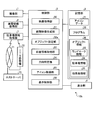
- FIG. 1 is a diagram illustrating a functional configuration example of the vehicle display device according to the first embodiment.
- FIG. 2 is a diagram illustrating an example of an overhead video display by the display unit.
- FIG. 3 is a diagram illustrating another display example of the overhead view video by the display unit.
- FIG. 4 is a flowchart illustrating an example of a display method of the vehicle display device according to the first embodiment.
- FIG. 5 is a diagram illustrating a functional configuration example of the vehicle display device according to the second embodiment.
- FIG. 6 is a flowchart illustrating an example of a display method of the vehicle display device according to the second embodiment.
- FIG. 7 is a diagram illustrating a modification of the overhead view video.
- FIG. 8 is a diagram illustrating a modified example of the overhead view video.
- FIG. 1 is a diagram illustrating a functional configuration example of the vehicle display device according to the first embodiment.
- FIG. 2 is a diagram illustrating an example of an overhead video display by the display unit.
- FIG. 9 is a diagram illustrating an example of the display of the overhead view video by the display unit.
- FIG. 10 is a diagram illustrating an example of a bird's-eye view image displayed on the display unit.
- FIG. 11 is a diagram illustrating a functional configuration example of the vehicle display device according to the third embodiment.
- FIG. 12 is a diagram illustrating an example of an overhead video display by the display unit.
- FIG. 13 is a flowchart illustrating an example of a display method of the vehicle display device according to the third embodiment.
- FIG. 14 is a flowchart illustrating an example of a display method of the vehicle display device according to the fourth embodiment.
- FIG. 15 is a flowchart illustrating an example of a parking lot exit designation method in the flowchart of FIG. 14.
- FIG. 16 is a diagram illustrating a modification example of the display of the overhead view video by the display unit.
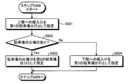
- FIG. 17 is a flowchart illustrating a modification of the parking lot exit designation method of the flowchart in FIG. 14 of the display method of the vehicle display device according to the fourth embodiment.
- FIG. 18 is a diagram illustrating a functional configuration example of the vehicle display device according to the fifth embodiment.
- FIG. 19 is a diagram illustrating an example of display of a bird's-eye view video by the display unit.
- FIG. 20 is a flowchart illustrating an example of a display method of the vehicle display device according to the fifth embodiment.
- FIG. 21 is a diagram illustrating a modification example of the display of the overhead view video by the display unit.
- FIG. 22 is a flowchart illustrating a modification of the display method of the vehicle display device according to the fifth embodiment.
- Embodiments of a display device for a vehicle according to the present invention will be described below in detail with reference to the drawings. Note that the present invention is not limited to the embodiments. Further, the constituent elements of this embodiment include those that can be replaced while maintaining the identity of the invention and that are obvious for replacement. In addition, a plurality of modifications described in this embodiment can be arbitrarily combined within a range obvious to those skilled in the art.
- FIG. 1 is a diagram illustrating a functional configuration example of the vehicle display device according to the first embodiment.
- the vehicle display device 10 according to the first embodiment is realized by the function of the control unit 5.
- the vehicle display device 10 may include an imaging unit 1, a vehicle information acquisition unit 2, a storage unit 3, and a display unit 4.
- the vehicle display device 10 is a device that can be used in a vehicle, and may be either a fixed type or a portable type.
- the imaging unit 1 captures an image of the surroundings of the host vehicle. For example, the imaging unit 1 captures a range of several meters from the host vehicle and acquires a video.
- the imaging unit 1 is a camera provided in the own vehicle.
- the imaging unit 1 acquires, for example, images of the front, rear, left side, and right side of the host vehicle, respectively.
- the imaging unit 1 outputs captured video data to a video acquisition unit 50 described later.
- the vehicle information acquisition unit 2 acquires the current position information of the host vehicle and information indicating the traveling direction.
- the vehicle information acquisition unit 2 is, for example, a GPS (Global Positioning System) receiver, and acquires the current position of the host vehicle from the received information.
- the vehicle information acquisition part 2 calculates the advancing direction of the own vehicle based on the position of the own vehicle acquired previously, and the present position of the own vehicle.
- the calculation of the traveling direction by the vehicle information acquisition unit 2 may be calculated by the control unit 5 from the acquired current position information.
- the vehicle information acquisition unit 2 may use a navigation device or the like.
- the storage unit 3 stores icon data 31.
- the icon data 31 is data for displaying an icon corresponding to the landmark on the display unit 4.
- the data may be unique data for each landmark of the icon data 31, or may be data for a common icon for each category such as a tower, building, or mountain.
- the storage unit 3 stores a program 32 executed by the control unit 5.
- the storage unit 3 can be realized by a semiconductor memory, a hard disk device, or the like.
- the storage unit 3 also stores landmark position information and height information as landmark information 33.
- the storage unit 3 may be provided in the vehicle display device 10 or may be provided in another device so that the vehicle display device 10 can refer to data by wire or wirelessly.
- the storage unit 3 may store map information.
- Display unit 4 displays data output from control unit 5.
- the display unit 4 can be realized by a liquid crystal display, for example.
- the display unit 4 may be a dedicated display unit of the vehicular display device 10 or may use a monitor of a navigation device.
- the control unit 5 includes a video acquisition unit 50, an overhead video generation unit 51, a landmark designation unit 52, a position information acquisition unit 53, a direction specification unit 54, an icon acquisition unit 55, and a display control unit 56. Have. Each of these units may be realized by, for example, a control unit 5 that is a CPU (Central Processing Unit) executing a program.
- a control unit 5 that is a CPU (Central Processing Unit) executing a program.
- the video acquisition unit 50 acquires the video captured by the imaging unit 1.
- the video acquisition unit 50 may perform a process of cutting out a range to be used as an overhead image from the video data acquired from the imaging unit 1.
- the overhead view video generation unit 51 generates an overhead view video based on the surrounding video acquired by the video acquisition unit 50.
- the overhead view image is an image viewed from above the host vehicle.
- the bird's-eye view image generation unit 51 generates a bird's-eye view image by converting the viewpoint of the surrounding image of the host vehicle as seen from above the host vehicle and synthesizing a virtual host vehicle image indicating the position of the host vehicle. For example, when the video acquisition unit 50 acquires the front, rear, left side, and right side images of the host vehicle, the overhead view video generation unit 51 performs viewpoint conversion on the front, rear, left side, and right side videos, A bird's-eye view image is generated by synthesizing them with the virtual host vehicle image.
- the landmark designation unit 52 designates a landmark.
- the landmark designated by the landmark designation unit 52 is designated as a designated landmark.
- a landmark visible from the vehicle window can be a designated landmark.
- a famous landmark such as a scenic spot or a conspicuous one can be used as the designated landmark.
- the designated landmark can target various fixed objects that can be used as landmarks, such as buildings, facilities, and the like, and natural objects such as mountains and rivers.
- the landmark is a direction indication target object.
- the direction indication target object is an object to be displayed as an icon in the overhead view video, and the icon is displayed in the overhead view video, so that the direction from the own vehicle and the positional relationship with the own vehicle can be indicated.
- the direction indication target object is not limited to a landmark.
- the landmark designation unit 52 can select at least one of the landmark candidates and set it as the designated landmark.
- the landmark candidates may be set in advance at the time of manufacturing or shipping the vehicle display device 10, or may be set by the driver after the vehicle display device 10 is shipped.
- the landmark designation unit 52 acquires map information from the storage unit 3 or the like, and inputs a landmark selected by the user or a name from the landmark candidates included in the map information displayed on the display unit 4.
- the selected landmark can be designated as the designated landmark.
- the designated landmark designated by the landmark designation unit 52 is a target for displaying the corresponding icon on the display unit 4.
- the user may specify a landmark candidate category.
- the landmark designation unit 52 extracts landmark candidates related to the category designated from the map information based on the current position of the host vehicle and displays them on the display unit 4. May select a designated landmark. In that case, the landmark candidates extracted by the landmark designation unit 52 are visible from the current position of the host vehicle.
- a designated landmark can be a thing less than 10 km from the current position of the own vehicle, and a mountain that is less than 100 km from the current position of the own vehicle.
- a high-rise building having a height of 150 m or more, a mountain having an altitude of 2500 m or more, and the like having a height of a predetermined value or more can be designated landmarks.
- Those included in the definition of the mountain of the Geographical Survey Institute may be designated landmarks. Even if it is not high, lakes and ponds may be designated landmarks.
- the height of the landmark may be an altitude (absolute value) or an altitude difference (relative value). If you get too close to the landmark, it may disappear from the car window. In that case, the icon need not be displayed. In that case, for example, it is desirable to display icons of other landmarks. Information regarding the height of the landmark may be acquired from another device via a communication line.
- the position information acquisition unit 53 acquires the position information of the designated landmark from the landmark information 33.
- the direction specifying unit 54 specifies the direction of the designated landmark around the host vehicle based on the current position and traveling direction of the vehicle and the position information of the designated landmark.
- the icon acquisition unit 55 acquires the icon of the designated landmark designated by the landmark designation unit 52.
- the icon acquisition unit 55 may acquire an icon corresponding to the designated landmark stored in the storage unit 3 or an icon corresponding to the designated landmark acquired from another device via the communication line. You may get it.
- the display control unit 56 adds data indicating a designated landmark to the position in the direction specified by the direction specifying unit 54 with respect to the overhead view video, and outputs data for display on the display unit 4.
- the operation of the vehicle display device 10 configured as described above will be described. While the host vehicle is traveling, the imaging unit 1 captures an image of the surroundings of the host vehicle. The vehicle information acquisition unit 2 acquires the current position of the host vehicle and calculates the traveling direction of the host vehicle. The overhead video generation unit 51 generates an overhead video based on the video acquired by the video acquisition unit 50.
- the landmark designation unit 52 designates a landmark and designates it as a designated landmark.
- the position information acquisition unit 53 acquires position information of the designated landmark.
- the direction specifying unit 54 specifies the direction of the designated landmark based on the current position and traveling direction of the host vehicle and the position information of the designated landmark.
- the icon acquisition unit 55 acquires the icon of the designated landmark designated by the landmark designation unit 52.
- the display control unit 56 outputs data obtained by adding an icon to the overhead view video.
- the display unit 4 displays data output from the display control unit 56. Through the above operation, the overhead view video is displayed on the display unit 4.
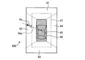
- FIG. 2 is a diagram illustrating an example of an overhead video display by the display unit 4.
- the bird's-eye view image 400 displayed by the display unit 4 includes a virtual host vehicle figure 40, a front image 41, a rear image 42, a left side image 43 and a right side image 44.
- the front image 41, the rear image 42, the left side image 43, and the right side image 44 are located around the virtual host vehicle figure 40.
- the front image 41 is at a position corresponding to the front direction of the virtual host vehicle figure 40
- the rear image 42 is at a position corresponding to the rear direction of the virtual host vehicle figure 40
- the left side image 43 is a virtual host vehicle.
- the right side image 44 is disposed at a position corresponding to the left side of the figure 40 and a position corresponding to the right side of the virtual host vehicle figure 40.
- the overhead image 400 includes an icon 6a.
- the icon 6a is an icon indicating a tower of a building.
- the icon 6a is arranged along an imaginary line 46a that is one of imaginary lines extending radially away from the center point 45 with the center point 45 of the host vehicle as a reference.
- the bird's-eye view image 400 in this example indicates that the direction in which the icon 6a is displayed is the direction in which the tower, which is a landmark, is located, with the host vehicle as the center. For this reason, a person on the vehicle can intuitively see the direction in which the traveling vehicle is currently facing or the direction of the landmark by checking the direction in which the icon 6a is displayed centering on the traveling vehicle. Can understand.
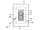
- FIG. 3 is a diagram showing another display example of the overhead view video by the display unit 4.
- FIG. 3 shows a state after the host vehicle has moved from the state shown in FIG.
- the bird's-eye view image 400 displayed by the display unit 4 includes icons 6b and 6c.
- the icon 6b is an icon indicating the same tower as the icon 6a shown in FIG.
- the vehicle is arranged along a virtual line 46b, which is one of the virtual lines that radiate away from the center point 45 of the host vehicle.
- the icon 6b is displayed at a position in a direction different from that shown in FIG.
- the icon 6c is an icon indicating a mountain in this example.
- the icon 6c is arranged along a virtual line 46c that is one of virtual lines that spread radially away from the center point 45 with the center point 45 of the host vehicle as a reference.
- the bird's-eye view image 400 in this example is centered on the host vehicle, the direction in which the icon 6b is displayed is the direction in which the tower whose designated landmark is located, and the direction in which the icon 6c is displayed is specified. Indicates that the mountain, which is a landmark, is located. For this reason, the person riding in the vehicle confirms the direction in which the two icons 6b and 6c are displayed around the own vehicle, so that the traveling vehicle is currently facing the direction or landmark. Can intuitively understand the direction of
- the icons 6a, 6b, and 6c may be displayed at positions close to the outer edge of the overhead view image 400. For example, assuming a virtual line 47 indicating an intermediate position between the virtual host vehicle figure 40 and the outer edge of the bird's-eye view image 400, icons 6a, 6b, and 6c are displayed outside the virtual line 47 and inside the bird's-eye view image 400. indicate. For this reason, in the bird's-eye view image 400, the icons 6a, 6b, and 6c can be displayed without affecting the image in the range close to the host vehicle.
- the vehicle display device 10 displays not only the image ahead of the host vehicle but also the designated landmark as an icon along with the image around the host vehicle.
- a person on the vehicle can confirm the direction of the designated landmark with respect to the own vehicle by confirming the icon of the designated landmark included in the overhead view video.
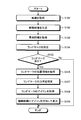
- FIG. 4 is a flowchart illustrating an example of a display method by the vehicle display device according to the first embodiment.
- a video around the host vehicle is acquired by the video acquisition unit 50 (step S101).
- the bird's-eye view video generation unit 51 Based on the acquired surrounding video, the bird's-eye view video generation unit 51 generates a bird's-eye view video by synthesizing the virtual host vehicle video indicating the position of the host vehicle by converting the viewpoint as seen from above the host vehicle (step S102).
- the vehicle information which shows the present position and traveling direction of the own vehicle is acquired from the vehicle information acquisition part 2 (step S103).
- the landmark designation unit 52 designates a landmark and designates it as a designated landmark (step S104).
- the position information acquisition unit 53 determines whether there is a designated landmark to be processed (step S105), and if it is determined that there is a designated landmark to be processed (Yes in step S105), the designated land.
- the mark position information is acquired (step S106).
- the direction specifying unit 54 specifies the direction of the designated landmark centered on the vehicle based on the current position and traveling direction of the host vehicle and the position information of the designated landmark (step S107).
- the icon acquisition unit 55 acquires an icon corresponding to the designated landmark (step S108).
- the display control unit 56 adds an icon to the overhead video and causes the display unit 4 to display the icon (step S109). If it is determined in step S105 that there is no designated landmark to be processed (No in step S105), the process ends.
- the above display method not only the image ahead of the host vehicle but also the surrounding image of the host vehicle is displayed as an icon. By confirming the icon of the designated landmark, the direction of the designated landmark with respect to the host vehicle can be confirmed.
- FIG. 5 is a diagram illustrating a functional configuration example of the vehicle display device according to the second embodiment.
- the vehicle display device 10 a according to the second embodiment has a configuration in which a perspective information acquisition unit 57 is added to the vehicle display device 10 illustrated in FIG. 1.
- the prospect information acquisition unit 57 acquires the prospect information indicating whether or not the designated landmark designated by the landmark designation unit 52 can be seen from the current position of the host vehicle.
- the perspective information may be stored as map information of the navigation device, for example. In that case, the perspective information acquisition unit 57 acquires the perspective information from the navigation device. Further, for example, the perspective information may be stored in an external server or the storage unit 3. In that case, the perspective information acquisition unit 57 may acquire the perspective information from another device via a communication line.
- the observation information acquisition unit 57 confirms whether or not the observation is possible based on the acquired observation information.
- the prospect information acquisition unit 57 may confirm the possibility of the prospect performed by obtaining the prospect information every predetermined time or every predetermined traveling distance.
- the view information acquisition unit 57 may check whether or not the view is possible, for example, every 30 seconds, or may check whether or not the view is possible every 100 m of the traveling distance of the host vehicle.
- the display control part 56 adds the icon which shows a designated landmark to a bird's-eye view image, when a prospect is possible by prospect information.
- the display control unit 56 does not add an icon indicating the designated landmark to the bird's-eye view video when the view information indicates that the view is not possible.
- a function may be provided that transmits, as word-of-mouth information, information on whether or not the designated landmark is visible with respect to the position of the host vehicle.
- the configuration of other components is the same as that of the vehicle display device 10 described with reference to FIG.
- the display example is also the same as that of the vehicle display device 10 described with reference to FIG.
- the operation of the vehicular display device 10a configured as described above will be described.
- the operation of the vehicle display device 10a is basically the same as the operation of the vehicle display device 10 according to the first embodiment described above.
- the difference from the operation of the vehicular display device 10 is that the perspective information acquisition unit 57 acquires the perspective information and determines whether or not the designated landmark can be viewed from the current position of the host vehicle based on the perspective information. .
- the direction specifying unit 54 determines whether the designated landmark is the same as the operation of the vehicle display device 10 according to the first embodiment. The direction is specified, and the icon acquisition unit 55 acquires an icon corresponding to the designated landmark.
- the prospect information acquisition unit 57 determines that the designated landmark cannot be seen from the current position of the host vehicle, the icon corresponding to the designated landmark is not obtained, and another designated landmark is set as a processing target.
- the icon corresponding to the designated landmark is acquired only when it is determined that the designated landmark can be viewed. Therefore, the designated landmark that cannot be seen is not added to the overhead view image and is being boarded. This makes it easier to understand the direction in which the traveling vehicle is currently facing or the direction of the landmark.
- the entire designated landmark may not be visible from the host vehicle, and only a part may be visible. For example, it may be hidden in another building and only the top half of the tower is visible, or it may be hidden in a building and only the right half of the mountain is visible.
- an icon may be displayed when the ratio of the visible range of the entire designated landmark exceeds a predetermined threshold. For example, an icon may be displayed when the range where the designated landmark is visible exceeds 50% of the whole designated landmark. In this case, the icon is not displayed when the range where the designated landmark can be seen does not exceed the threshold.
- the icon area may be displayed in half.
- the icon area may be displayed in half.
- only the upper half of the tower is visible, only the upper half of the icon may be displayed, or only the right half or the left half may be displayed.
- a person in the vehicle may be allowed to set the icon display mode by the landmark designation unit 52.
- FIG. 6 is a flowchart showing an example of a display method by the vehicle display device according to the second embodiment of the present invention. As shown in FIG. 6, steps S201 and S202 are added to the display method according to the second embodiment in the display method according to the first embodiment described with reference to FIG.
- step S106 after the position information acquisition unit 53 acquires the position information of the designated landmark, the perspective information acquisition unit 57 acquires the perspective information (step S201).
- the perspective information acquisition unit 57 determines whether or not the designated landmark can be viewed from the current position of the host vehicle based on the acquired perspective information (step S202).
- step S202 If it is determined in step S202 that the designated landmark can be viewed from the current position of the host vehicle (Yes in step S202), the process proceeds to step S107, and the direction specifying unit 54 determines the current position and traveling direction of the host vehicle, and the designated land. Based on the mark position information, the direction of the designated landmark centered on the vehicle is specified (step S107). If it is determined in step S202 that the designated landmark cannot be viewed from the current position of the host vehicle (No in step S202), the process returns to step S105, and the position information acquisition unit 53 determines whether there is a designated landmark to be processed. It is determined whether or not (step S105). In FIG. 6, other steps are the same as those in the display method of the first embodiment described with reference to FIG.
- the designated landmark icon is acquired only when it is determined that the prospective information is obtained and the designated landmark can be seen, so that the designated landmark that cannot be seen is not added to the overhead view video.
- a person on board can more easily understand the direction in which the traveling vehicle is currently facing or the direction of the landmark.
- each part in the control part 5 of the vehicle display apparatuses 10 and 10a is realizable when CPU runs a program.
- This program can be loaded from the storage unit 3 to the control unit 5 or can be loaded from another device to the control unit 5 via a communication line.
- This program is a bird's-eye view of a computer operating as a display device for a vehicle, in which a video of the surroundings of the vehicle is converted to a viewpoint as seen from above the vehicle, and a virtual vehicle image indicating the position of the vehicle is synthesized.
- It is a display program for functioning as a means for adding and displaying an icon.
- FIG. 7 is a diagram illustrating a first modification of the overhead view video.
- the bird's-eye view image 400a of this example includes a virtual host vehicle figure 40a, a front image 41a, a rear image 42a, a left side image 43a, and a right side image 44a.
- the size of the virtual host vehicle figure 40 in the display example described with reference to FIGS. 2 and 3 is indicated by a broken line 40h.
- the display control unit 56 outputs data using a virtual host vehicle figure 40a having a smaller size than the virtual host vehicle figure 40 indicated by the broken line 40h. For this reason, even if the icons 6b and 6c are added to the bird's-eye view image 400a, a sufficient area for displaying the image around the host vehicle can be secured. In particular, when the number of displayed icons is large, it is possible to check an image around the host vehicle without being obstructed by the icons.
- FIG. 8 is a diagram illustrating a second modification of the overhead view video.
- a monitor having a display area that displays other information in addition to the overhead view video such as a monitor of a navigation device, is used as the display unit 4.
- the bird's-eye view image 400b of this example is displayed on the right side of the horizontally long screen 401.
- the bird's-eye view image 400b includes a virtual host vehicle figure 40b, a front image 41b, a rear image 42b, a left side image 43b, and a right side image 44b. Icons 6d and 6e are displayed in the display area outside the bird's-eye view video 400b.
- a part of the icons 6d and 6e is displayed in close contact with the edge of the overhead view image 400b.
- the display control unit 56 outputs data obtained by adding icons 6d and 6e to the outside of the overhead view video 400b. For this reason, even if the icons 6d and 6e are added to the overhead view video 400b, it is possible to secure a sufficient area for displaying the video around the host vehicle. In particular, when the number of displayed icons is large, it is possible to check an image around the host vehicle without being obstructed by the icons.
- FIG. 9 and FIG. 10 are diagrams showing an example of an overhead video display by the display unit 4.
- 9 is a diagram corresponding to FIG. 2 described above
- FIG. 10 is a diagram corresponding to FIG. 3 described above.
- highlighting is added to an area 48a corresponding to the window in which the icon 6a is displayed in the virtual host vehicle figure 40.
- 10 is highlighted in the region 48a corresponding to the window where the icon 6b is displayed and the region 48b corresponding to the window where the icon 6c is displayed in the virtual host vehicle figure 40.
- the display control unit 56 outputs the data with the highlighted display.
- the highlighting for example, in the bird's-eye view image 400c and the bird's-eye view image 400d, display in a color (for example, red) different from other parts, display with high luminance, blinking display, and the like.
- These highlights guide the direction in which the designated landmark can be seen (should be seen), and it is clear that the landmark can be confirmed by looking outside the window in the direction of the area 48a in the window of the host vehicle. Become. This makes it easier for the person on board to find the designated landmark.
- the vehicular display devices 10 and 10a are used for the purpose of sightseeing guidance or scenery navigation, these highlighted displays are a great advantage.
- the icon size may be changed for display. For example, a designated landmark that is far from the host vehicle may be displayed with a smaller icon, and a designated landmark that is closer to the distance may be displayed with a larger icon.
- a person on the vehicle can intuitively understand the distance from the vehicle to the designated landmark, making it easy to find the designated landmark. Become.
- the icon may not be displayed depending on the speed of the host vehicle. That is, the speed of the host vehicle may be used as a trigger for icon display. For example, the icon may not be displayed when the vehicle speed is low (for example, traveling at a speed of less than 20 km / second), and the icon may be displayed when the vehicle speed is high. When the vehicle speed is low, it is considered that the driver often uses a bird's-eye view video for entering the garage, etc. Therefore, if the icon is not displayed in that case, the driver can concentrate on the steering wheel operation etc. .
- Whether or not to display the icon may be determined depending on the region where the host vehicle is traveling. For example, the icon may not be displayed when traveling in an urban area, and the icon may be displayed when traveling in a suburb. Since there are many buildings that are designated landmarks in urban areas, icons may not be displayed, and icons may be displayed in the suburbs because it is often necessary to have landmarks during travel. Whether the traveling area is an urban area or a suburb may be determined by defining a boundary in advance and comparing it with the current position.
- the icon may be displayed only when the road travels for the first time (the road whose number of travels is a predetermined number or less).
- the road travels for the first time the road whose number of travels is a predetermined number or less.
- the number of icons to be displayed is increased, and when the road is the second or subsequent road (the number of travels exceeds the predetermined number). May reduce the number of icons to be displayed.
- the vehicle display devices 10 and 10a may be integrated with the navigation device or may be a dedicated device independent of the navigation device.
- the navigation destination may be a designated landmark. In this case, a special icon indicating the destination may be displayed on the display unit 4.
- FIG. 11 is a diagram illustrating a functional configuration example of the vehicle display device according to the third embodiment.
- the vehicle display device 10 b according to the third embodiment is realized by the function of the control unit 5.
- the vehicle display device 10 b includes an imaging unit 1, a vehicle information acquisition unit 2, a storage unit 3, a display unit 4, and a parking lot information acquisition unit 7.
- the vehicle display device 10b is a device that can be used in a vehicle, and may be either a fixed type or a portable type.
- the points peculiar to the vehicle display device 10b will be described mainly. The description of the same configuration as the vehicle display device 10 is omitted.
- the storage unit 3 stores object information 36.
- the object information 36 includes landmark information 33, parking lot information 34, and other vehicle information 35.
- the landmark information 33 includes landmark position information and height information.
- the parking lot information 34 includes parking lot exit information.
- the parking lot exit includes the parking entrance.
- Other vehicle information 35 includes position information of other vehicles.
- the object information 36 may be stored in the storage unit 3 in advance.
- the vehicle display device 10b refers to data of another device by wire or wirelessly, and is acquired from the other device and stored in the storage unit 3. Also good.
- the parking lot information acquisition unit 7 acquires parking lot information corresponding to the current position of the host vehicle based on the current position information of the host vehicle.
- the parking lot information acquisition unit 7 acquires, for example, parking lot information stored in the host server 73 through the Internet line 71.
- the host server 73 acquires and stores parking lot information from parking lots not shown through the Internet line 71.
- the parking lot information acquisition unit 7 may acquire parking lot information from the ITS roadside machine 72.
- the parking lot information acquisition part 7 may acquire parking lot information at the time of parking of the own vehicle.
- the acquired parking lot information is stored in the storage unit 3 as parking lot information 34.
- the parking lot information 34 may be stored in the storage unit 3 in advance.
- the parking lot information acquisition unit 7 acquires accurate parking lot information even when the parking lot information is acquired when the parking lot of the host vehicle enters the parking lot, even in a temporary parking lot where the exit position changes frequently. can do.
- the object designating unit 52a designates a direction instruction target object to be displayed on the display unit 4.
- the direction indication target object specified by the object specifying unit 52a is set as a specified object.
- the direction indication target object includes exits of parking lots in various places. Based on the parking lot information acquired by the parking lot information acquisition unit 7, the object specifying unit 52a specifies the exit of the parking lot corresponding to the current position of the host vehicle as the designated object.
- the position information acquisition unit 53 acquires the position information of the host vehicle based on the map information and the vehicle information, and determines the current position of the host vehicle. Further, when it is determined that the current position of the host vehicle is in the parking lot, the position information acquisition unit 53 acquires position information of the exit of the parking lot corresponding to the current position of the host vehicle.
- the operation of the vehicle display device 10b will be described.
- the operation of the vehicle display device 10b is basically the same as the operation of the vehicle display device 10 according to the first embodiment described above.
- the difference from the operation of the vehicular display device 10 is that the parking lot information acquisition unit 7 acquires the parking lot information and specifies the exit of the parking lot as a designated object based on the parking lot information.
- the parking lot information acquisition unit 7 acquires parking lot information when the host vehicle is in the parking lot.
- the object designating unit 52a designates the parking lot exit as the designated object.
- the parking lot information acquisition unit 7 does not operate, and the object designating unit 52a designates the landmark as the designated object.
- the position information acquisition unit 53 acquires the position information of the specified object
- the direction finger specifying unit 54 specifies the direction of the specified object
- the icon acquisition unit. 55 acquires an icon corresponding to the designated object.
- the object designating unit 52a designates the parking lot exit as the designated object
- the icon obtaining unit 55 obtains the icon corresponding to the parking lot exit.
- the landmark outside the parking lot is not displayed on the display unit 4 in the parking lot, and the person on board can easily understand the traveling direction of the traveling vehicle in the parking lot.
- FIG. 12 is a diagram illustrating an example of an overhead video display by the display unit 4.
- a bird's-eye view image 400e shown in FIG. 12 includes an icon 6d.
- the icon 6d is an icon indicating the direction of the parking lot exit.
- the icon 6d is arranged along a virtual line 46d that is one of virtual lines that spread radially away from the center point 45 with the center point 45 of the host vehicle as a reference.
- the bird's-eye view image 400e of this example indicates that the direction in which the icon 6d is displayed is the direction in which the exit of the parking lot that is the designated object is located, with the host vehicle as the center.
- the icon 6d may be an icon in the form of an arrow indicating the direction in which the parking lot exit is located. For this reason, the person riding in the vehicle confirms the direction in which the icon 6d is displayed centering on the own vehicle, thereby determining the direction in which the traveling vehicle is currently facing or the direction of the parking lot exit. Intuitively understand.
- the other components are the same as those in the bird's-eye view image 400 described with reference to FIG.
- FIG. 13 is a flowchart showing an example of a display method by the vehicle display device according to the third embodiment of the present invention.
- the video acquisition unit 50 acquires a video around the host vehicle (step S301).
- the bird's-eye view video generation unit 51 Based on the acquired surrounding video, the bird's-eye view video generation unit 51 generates a bird's-eye view video by synthesizing the virtual host vehicle video indicating the position of the host vehicle by converting the viewpoint as seen from above the information of the host vehicle (step).
- the vehicle information acquisition part 2 acquires the vehicle information which shows the present position and the advancing direction of the own vehicle (step S303).
- the position information acquisition unit 53 acquires the map information stored in the storage unit 3 (step S304).
- the parking lot information acquisition unit 7 determines whether or not the own vehicle is in the parking lot (step S305), and determines that the current position of the own vehicle is in the parking lot (Yes in step S305), the parking lot information.
- Obtain step S306.
- the object designating unit 52a designates the entrance of the parking lot as the exit of the designated parking lot (step S307), and the position information obtaining unit 53 obtains the location information of the parking lot exit (step S308). .
- the direction specifying unit 54 specifies the direction of the parking lot exit centered on the vehicle based on the current position and traveling direction of the host vehicle and the location information of the parking lot exit (step S309).
- the icon acquisition part 55 acquires the icon corresponding to the exit of a parking lot (step S310).
- the display control unit 56 adds an icon of a parking lot exit to the overhead view video at the direction position specified by the direction specifying unit 54 and causes the display unit 4 to display the icon (step S316).
- step S305 when it is determined that the current position of the host vehicle is not in the parking lot (No in step S305), the object designating unit 52a designates a landmark to be displayed on the display unit 4, and designates the designated object. (Step S311).
- the position information acquisition unit 53 determines whether there is a landmark that is a designated object to be processed (step S312), and determines that there is a landmark that is a designated object to be processed (step S312). Yes), the position information of the landmark that is the designated object is acquired (step S313).
- the direction specifying unit 54 specifies the direction of the landmark that is the designated object around the vehicle based on the current position and traveling direction of the host vehicle and the position information of the landmark that is the designated object (step S314).
- the icon acquisition unit 55 acquires an icon corresponding to the landmark that is the designated object (step S315).
- the display control unit 56 adds the landmark icon, which is the designated object, to the bird's-eye view video and causes the display unit 4 to display the icon (step S316). If it is determined in step S312 that there is no landmark that is the designated object to be processed (No in step S312), the process ends.
- the host vehicle when the host vehicle is in the parking lot, not only the image ahead of the host vehicle but also the surrounding image of the host vehicle is displayed as an icon.
- the icon of the parking lot exit By confirming the icon of the parking lot exit, the direction of the parking lot exit relative to the host vehicle can be confirmed.
- the functional configuration of the vehicular display device according to the fourth embodiment of the present invention is basically the same as the configuration example of the vehicular display device 10b shown in FIG. In the fourth embodiment, the following description will be given for a case where the target parking lot is multi-level.
- the parking lot information acquired by the parking lot information acquisition unit 7 includes altitude information for each level and exit information for each level when the target parking lot has multiple levels.
- the direction indication target object specified by the object specifying unit 52a further includes a parking lot exit for each level of the parking lot corresponding to the current position of the host vehicle. Based on the parking lot level information acquired by the parking lot information acquisition unit 7, the object specifying unit 52a specifies a parking lot exit corresponding to the current position of the host vehicle as a specified object.
- the exit of the parking lot includes an entrance for the parking lot, an entrance to the upper floor for each level, and an entrance to the lower floor.
- the position information acquisition unit 53 acquires latitude, longitude, and altitude information as the position information of the own vehicle, and the parking lot where the own vehicle exists based on the position information and the parking lot information of the own vehicle. Identify the hierarchy.
- the position information acquisition unit 53 can identify the position information of the host vehicle by acquiring the position information of the host vehicle of latitude, longitude, and hierarchy for each hierarchy from the on-site GPS transmission unit installed in the parking lot. Also good.
- the position information acquisition part 53 acquires the positional information on the exit of the parking lot of the hierarchy applicable to the present position of the own vehicle in the parking lot of a multi-story floor.
- Display example The display example of this example is the same as the display example of the overhead view image described with reference to FIG.
- FIG. 14 is a flowchart showing an example of a display method by the vehicle display device according to the fourth embodiment of the present invention.
- FIG. 15 is a flowchart showing an example of a parking lot exit designation method according to the fourth embodiment of the present invention in step S407 of the flowchart of FIG.
- the video acquisition unit 50 acquires a video around the host vehicle (step S401). Based on the acquired surrounding video, the bird's-eye view video generation unit 51 generates a bird's-eye view video by synthesizing the virtual host vehicle video indicating the position of the host vehicle by converting the viewpoint as seen from above the information of the host vehicle (step). S402). Moreover, the vehicle information acquisition part 2 acquires the vehicle information which shows the present position and traveling direction of the own vehicle (step S403).
- the position information acquisition unit 53 acquires the map information stored in the storage unit 3 (step S404).
- the parking lot information acquisition unit 7 determines whether or not the own vehicle is in the parking lot (step S405), and determines that the current position of the own vehicle is in the parking lot (Yes in step S405), the parking lot information.
- Obtain step S406.
- the position information acquisition unit 53 acquires the floor position information of the parking lot corresponding to the current position of the host vehicle (step S407).
- the object designating unit 52a designates the parking lot exit corresponding to the current location of the own vehicle as an example of the designation method of the parking lot exit in FIG. (Step S408).
- the object designating unit 52a determines whether or not the host vehicle is operating the engine (step S501), and the host vehicle is operating the engine. (Yes in step S501), the process proceeds to a step of determining whether or not it is less than a predetermined time (for example, 5 minutes) from the time when the host vehicle enters the parking lot (step S502). If it is determined that it is less than the predetermined time from when the host vehicle enters the parking lot (Yes in step S502), the object designating unit 52a designates the entrance to the upper floor as the exit of the designated parking lot. (Step S503), the process proceeds to Step S409 in the flowchart of FIG.
- a predetermined time for example, 5 minutes
- step S501 If it is determined in step S501 that the host vehicle is not operating (the engine is stopped) (No in step S501), it is determined whether or not a predetermined time has elapsed since the engine of the host vehicle stopped ( In step S504), when it is determined that a predetermined time has elapsed since the time when the engine of the host vehicle stopped (Yes in step S504), the object designating unit 52a parks the parking lot at the level of the parking lot corresponding to the current position of the host vehicle. The process proceeds to a step (step S505) for determining whether or not there is an entry gate.
- step S505 When it is determined in step S505 that there is a parking lot entrance (Yes in step S505), the object designating unit 52a designates the parking lot entrance as an exit of the designated parking lot (step S506), The process proceeds to step S409 in the flowchart of FIG.
- step S505 when it is determined that there is no parking lot entry (No in step S505), the object designating unit 52a designates the entrance to the lower floor as the exit of the designated parking lot (step S507). Then, the process proceeds to step S409 in the flowchart of FIG.
- step S502 if it is determined that a predetermined time or more has elapsed since the time when the host vehicle entered the parking lot (No in step S502), is there a parking lot entrance at the level of the parking lot where the host vehicle is located? It progresses to the step (step S505) which judges whether or not.
- step S504 If it is determined in step S504 that the predetermined time has not elapsed since the time when the vehicle stopped the engine (No in step S504), the process returns to step S501.
- step S409 the position information acquisition unit 53 acquires the position information of the parking lot exit. Since the flow from step S409 to step S411 is the same as the flow from step S308 to step S310 shown in FIG.
- the display control unit 56 adds an icon of a parking lot exit to the overhead view video in the direction specified by the direction specifying unit 54 and displays the icon on the display unit 4 (step S417).
- step S405 If it is determined in step S405 that the current position of the host vehicle is not the entrance of the parking lot (No in step S405), the process proceeds to a step (step S412) in which the object designating unit 52a designates a landmark. Since the flow from step S412 to step S416 is the same as the flow from step S311 to step S315 shown in FIG.
- the display control unit 56 adds the landmark icon, which is the designated object, to the bird's-eye view video and causes the display unit 4 to display it (step S417). If it is determined in step S413 that there is no landmark that is the designated object to be processed (No in step S413), the process ends.
- the object designating unit 52a designates the entrance to the lower floor as the exit of the parking lot that is the designated object.
- the parking lot information acquisition part 7 is an underground parking lot. If the parking lot information related to the multi-tier parking lot that has the entrance to the parking lot such as the top floor and extends toward the lower floor is acquired, the “entrance to the upper floor” in step S503 is “entrance to the lower floor”. In step S507, the “entry to the lower floor” is replaced with “entry to the upper floor”, and the flow is executed, so that the vehicle display device according to the fourth embodiment includes a display unit. An overhead view video can be displayed on the screen.
- the host vehicle when the host vehicle is in the parking lot, not only the image ahead of the host vehicle but also the surrounding image of the host vehicle is displayed as an icon.
- the icon of the parking lot exit By confirming the icon of the parking lot exit, the direction of the parking lot exit relative to the host vehicle can be confirmed.
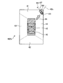
- FIG. 16 is a diagram illustrating an example of a bird's-eye view image displayed by the display unit 4.
- the bird's-eye view image 400f displays two icons indicating the exit of the parking lot.
- Icon 6e and icon 6f are icons indicating the exit of the first parking lot and the exit of the second parking lot.
- the entrance to the upper floor may be designated as the exit of the first parking lot that is the designated object, and the entrance to the lower floor may be designated as the exit of the second parking lot that is the designated object.
- FIG. 16 is a diagram illustrating a modification of the display of the overhead view video by the display unit 4.
- the overhead view image 400f shown in FIG. 16 includes an icon 6e and an icon 6f.
- the icon 6e and the icon 6f are arranged so as to overlap with a plurality of virtual lines 46e and 46f that spread radially away from the center point 45 with the center point 45 of the host vehicle as a reference.
- the bird's-eye view image 400f of the present example is centered on the own vehicle, and by confirming the direction displayed by the icon 6e and the icon 6f, the traveling vehicle is currently facing or the direction of the parking lot exit. Can be understood intuitively.
- the other components are the same as those in the bird's-eye view image 400 described with reference to FIG.
- FIG. 17 is a flowchart illustrating a modification of the parking lot exit designation method.
- multiple entry points of the parking lot at the level corresponding to the current position of the host vehicle, the entrance to the upper floor, or the entrance to the lower floor are designated as exits of the designated object parking lot, indicate.
- the object designating unit 52a designates the entrance to the upper floor as the exit of the first parking lot (step S601).
- the object designating unit 52a determines whether or not there is a parking lot entrance at the level corresponding to the current position of the host vehicle (step S602), and the parking lot entrance is at the level corresponding to the current position of the host vehicle. (Yes in step S602), the entrance of the parking lot is designated as the exit of the second parking lot (step S603), and the process proceeds to step S409 in the flowchart of FIG.
- step S602 when it is determined that there is no parking lot entrance at the level where the host vehicle is located (No in step S602), the object designating unit 52a uses the entrance to the lower floor as the exit of the second parking lot. Designate (step S604), the process proceeds to step S409 in the flowchart of FIG.
- the object designating unit 52a designates only the entrance to the lower floor as the parking lot exit. Moreover, in FIG. 17, although the entrance of a parking lot such as a three-dimensional parking lot was described in the lowest hierarchy and extended to the upper floor, the parking lot information acquisition unit 7 When the parking lot information about the multi-level parking lot that has the entrance to the parking lot at the top level and extends toward the lower floor is acquired, the “entrance to the upper floor” in step S601 becomes the “entrance to the lower floor”. In step S603, the flow is executed by replacing the “entrance to the lower floor” with the “entrance to the upper floor”, whereby the vehicle display device according to the present example displays an overhead video on the display unit. Can be displayed.
- the vehicular display device 10b when the host vehicle is in the parking lot, the vehicular display device 10b has an exit from the first parking lot as well as an image in front of the host vehicle as well as an image around the host vehicle. And the exit of the 2nd parking lot is displayed with an icon.
- the exit of the parking lot may be a parking entrance, an entrance to the upper floor, or an entrance to the lower floor.
- FIG. 18 is a diagram illustrating a functional configuration example of a vehicle display device according to the fifth embodiment of the present invention.
- the vehicle display device 10 c according to the fifth embodiment is realized by the function of the control unit 5.
- the vehicle display device 10bc includes an imaging unit 1, a vehicle information acquisition unit 2, a storage unit 3, a display unit 4, an other vehicle item input unit 8, and an other vehicle information acquisition unit 9. Also good.
- the vehicle display device 10c is a device that can be used in a vehicle, and may be either a fixed type or a portable type.
- the other vehicle is another vehicle heading to the same destination as the host vehicle.
- the object information 36 is the same as the object information 36 described in the vehicle display device according to the third embodiment of the present invention.
- the direction indication target object specified by the object specifying unit 52a includes vehicles other than the own vehicle.
- the object designating unit 52a can use other vehicles registered in advance as designated objects. For example, other vehicles heading to the same destination can be designated objects.
- the position information acquisition unit 53 acquires the position information of the designated object from the object information 36.
- the position information acquisition unit 53 acquires the position information of the other vehicle from the map information and the other vehicle information 35.
- the person who gets on the own vehicle inputs the other vehicle registration item by the other vehicle item input unit 8 and registers it in the vehicle display device 10c.
- the other vehicle information acquisition unit 9 acquires vehicle information stored in the host server 92 through the Internet line.
- the host server 92 acquires and stores other vehicle information from the vehicle information transmission unit 94 installed in the other vehicle 93 registered in advance through the Internet line 791.
- the other vehicle information includes the current position of the other vehicle.
- the other vehicle information acquired by the other vehicle information acquisition unit 9 is stored in the other vehicle information 35 of the storage unit 3.
- the own vehicle and the other vehicle can refer to each other's position information through the Internet line.
- the configuration of other components is the same as that of the vehicle display device 10 described with reference to FIG.
- the operation of the vehicular display device 10c configured as described above will be described.
- the operation of the vehicle display device 10c is basically the same as the operation of the vehicle display device 10 according to the first embodiment described above.
- the difference from the operation of the vehicle display device 10 is that the other vehicle registration item is registered in the vehicle display device 10c by the other vehicle item input unit 8, and the other vehicle information acquisition unit 9 acquires the registered other vehicle information.
- the other vehicle is designated as a designated object.
- the person who gets on the own vehicle registers the other vehicle registration item in the vehicle display device 10c through the other vehicle item input unit 8.
- the other vehicle information acquisition part 9 acquires the other vehicle information of the vehicle registered previously.
- the object designating unit 52 a designates another vehicle as a designated object to be displayed on the display unit 4.
- the position information acquisition unit 53 acquires the position information of the specified object
- the direction finger specifying unit 54 specifies the direction of the specified object
- the icon acquisition unit. 55 acquires an icon corresponding to the designated object.
- FIG. 19 is a diagram illustrating an example of a bird's-eye view image displayed on the display unit 4.
- a bird's-eye view image 400g shown in FIG. 19 includes an icon 6g and an icon 6G.
- the icon 6g is an arrow icon indicating the direction of the current position of the other vehicle
- the icon 6G is an icon indicating the other vehicle.
- the arrow icon 6g and the other vehicle icon 6G are arranged so as to overlap the virtual line 46g, which is one of the virtual lines extending radially away from the central point 45 with the central point 45 of the host vehicle as a reference.
- the bird's-eye view image 400g in this example shows that the direction in which the arrow icon 6g is displayed is the direction in which the other vehicle that is the designated object is located, with the vehicle at the center. An icon 6G is displayed. For this reason, the person riding in the vehicle checks the direction in which the arrow icon 6g and the vehicle icon 6G are displayed centering on the own vehicle, so that the traveling vehicle is currently facing or Intuitively understand the direction of other vehicles.
- the configuration of each other part is the same as that of the overhead view image 400 described with reference to FIG.
- FIG. 20 is a flowchart showing an example of a display method by the vehicle display device according to the fifth embodiment of the present invention.
- the person who gets on the own vehicle registers the other vehicle registration item in the other vehicle item input unit 8 (step S701).
- the video acquisition unit 50 acquires a video around the host vehicle (step S702).
- the bird's-eye view video generation unit 51 Based on the acquired surrounding video, the bird's-eye view video generation unit 51 generates a bird's-eye view video by synthesizing the virtual host vehicle video indicating the position of the host vehicle by converting the viewpoint as seen from above the information of the host vehicle (step). S703).
- the vehicle information acquisition part 2 acquires the vehicle information which shows the present position and traveling direction of the own vehicle (step S704).
- the object designating unit 52a designates another vehicle registered in advance as another vehicle that is a designated object (step S705), and the position information obtaining unit 53 is obtained by the other vehicle information obtaining unit 9 and stored in the storage unit 3.
- the position information of the other vehicle is acquired from the other vehicle information 35 (step S706).
- the direction specifying unit 54 specifies the direction of the other vehicle around the vehicle based on the current position and traveling direction of the host vehicle and the position information of the other vehicle (step S707).
- the icon acquisition part 55 acquires the icon corresponding to the other vehicle registered previously (step S708).
- the display control unit 56 adds an icon to the overhead view video and causes the display unit 4 to display the icon. (Step S709).
- the vehicular display device 10c displays other vehicles registered in advance as icons together with the video around the host vehicle. By confirming the icon of the other vehicle, the direction of the other vehicle with respect to the own vehicle can be confirmed.
- the position information acquisition unit 53 is further based on the previously acquired position of the other vehicle and the current position of the other vehicle.
- the traveling direction of the other vehicle may be calculated.
- the calculation of the traveling direction by the position information acquisition unit 53 may be calculated by the control unit 5 from the acquired current position information.
- the traveling direction information of the other vehicle acquired by the position information acquisition unit 53 is stored in the other vehicle information 35 of the storage unit 3.
- the icon acquisition unit 55 may further reflect the traveling direction on the icon 6h of the other vehicle.
- the display unit 4 may further add an icon of another vehicle facing in the traveling direction to the overhead view video.
- FIG. 21 is a diagram illustrating a modification example of the display of the overhead video by the display unit 4.
- a bird's-eye view image 400h illustrated in FIG. 21 includes an icon 6h and an icon 6H.
- the icon 6h is an arrow icon indicating the direction of the current position of the other vehicle
- the icon 6H is an icon of the other vehicle indicating the traveling direction of the other vehicle.
- the arrow icon 6h and the other vehicle icon 6H are arranged along a virtual line 46h that is one of virtual lines that spread radially away from the center point 45 with reference to the center point 45 of the host vehicle.
- the bird's-eye view image 400h in this example shows that the direction in which the arrow icon 6h is displayed is the direction in which the other vehicle that is the designated object is located, with the traveling direction ahead of the arrow.
- the icon 6H of the other vehicle shown is displayed.
- the icon 6H of the other vehicle is arranged so as to overlap with a virtual line 6U indicating the traveling direction of the other vehicle from the rear part 6S of the icon 6H toward the front part 6T.
- FIG. 22 is a flowchart showing an example of a display method by the vehicle display device according to the modification of the fifth embodiment of the present invention. Steps S801 to S806 in the flowchart in the present modification are the same as steps S701 to S706 in the flowchart showing an example of the display method by the vehicle display device according to the fifth embodiment.
- the position information acquisition unit 53 after the position information acquisition unit 53 acquires the position information of the other vehicle (step S806), the position information acquisition unit 53 further acquires the traveling direction information of the other vehicle (step S807).
- the direction specifying unit 54 specifies the direction of the other vehicle centering on the own vehicle (step S808), and the icon acquiring unit 55 An arrow icon 6H indicating the direction of the vehicle and a vehicle icon 6h indicating the traveling direction of the other vehicle are acquired (step S809), and the display control unit 56 adds the icon 6H and the icon 6h to the overhead view video, and displays the display unit. 4 is displayed. (Step S810).
- the vehicle display device 10c displays the direction of the other vehicle with an icon in the form of an arrow and the traveling direction of the other vehicle with an icon in the form of a vehicle, along with an image around the host vehicle.
- the vehicle display devices 10 and 10a described above add and display a designated landmark as an icon on the overhead view video.
- the vehicle display devices 10 and 10a display designated landmarks around the host vehicle with icons.
- the position of the host vehicle (which direction it faces) can be presented to a driver or the like in an easily understandable manner. Even if you are driving on unfamiliar land, the current position of your vehicle can be easily determined even if you are traveling on unfamiliar land by clearly showing the direction in which the target landmark can be seen from the vehicle you are riding Can be recognized.
- the vehicle display device 10b described above adds the parking lot exit, which is the designated object, to the overhead view video as an icon for display.
- the vehicle display device 10b displays an exit of the parking lot with an icon only when the host vehicle is in the parking lot. Thereby, the person riding in the vehicle can easily understand the relative direction of the exit of the parking lot with respect to the own vehicle, not the actual direction.
- the vehicle display device 10b can easily present the position and traveling direction of the host vehicle to a driver or the like. By clearly presenting the exit of the target parking lot from the vehicle being boarded, even if it is the first parking lot, the person on the vehicle can easily recognize the current position in the parking lot of the own vehicle it can.
- the vehicle display devices 10c and 10d described above add and display other vehicles as designated objects as icons on the overhead view video.
- the vehicle display devices 10c and 10d display other vehicles around the host vehicle with icons. Thereby, the person riding in the vehicle can easily understand the relative direction of the other vehicle with respect to the own vehicle, not the actual direction.
- a person who is on the vehicle even when traveling on an unfamiliar land by clearly presenting another vehicle registered in advance from the vehicle being boarded Can easily recognize the position of another vehicle relative to the host vehicle.
Landscapes
- Engineering & Computer Science (AREA)
- Remote Sensing (AREA)
- Radar, Positioning & Navigation (AREA)
- Physics & Mathematics (AREA)
- General Physics & Mathematics (AREA)
- Theoretical Computer Science (AREA)
- General Engineering & Computer Science (AREA)
- Human Computer Interaction (AREA)
- Automation & Control Theory (AREA)
- Multimedia (AREA)
- Signal Processing (AREA)
- Navigation (AREA)
- Instructional Devices (AREA)
Abstract
車両用表示装置は、車両の周囲を撮影した映像を取得する映像取得部と、映像取得部が取得した映像を、車両の上方から見たように視点変換して車両の位置を示す仮想自車両映像を合成した俯瞰映像を生成する俯瞰映像生成部と、方向指示対象オブジェクトを指定して指定オブジェクトとするオブジェクト指定部と、指定オブジェクトの位置情報を取得する位置情報取得部と、車両の現在位置および進行方向を取得する車両情報取得部と、現在位置および進行方向と指定オブジェクトの位置情報とに基づき、車両を中心とした指定オブジェクトの方向を特定する方向特定部と、俯瞰映像に対して方向特定部で特定された方向に指定オブジェクトを示すアイコンを付加して表示部に表示させる表示制御部と、を備える。
Description
本発明は、車両用表示装置、表示方法および表示プログラムに関する。
車載用ナビゲーション装置には、走行時の目印となるランドマークを地図上に表示する機能を備えているものがある。ランドマークとしてはガソリンスタンド等の施設が表示できる。車載用ナビゲーション装置は、表示している地図の車両が走行している経路に存在する施設の位置にランドマークに対応するマークを表示させる。車載用ナビゲーション装置は、ランドマークを表示させることで、ユーザが地図上に表示されているマークと車両から実際に見える施設とを比べて、自車両の現在位置や右左折する交差点等の確認をしやすくすることができる。
特許文献1には、遠くからでも位置を確認できる特定のランドマークを使用し、そのランドマークが見える方向を地図上に表示する技術が記載されている。
特許文献1に記載の技術では、地図上では車両と対象となるランドマークとの位置関係を把握できるが、実際に乗車している自車両のどの方向に対象となるランドマークが存在するのか、明確ではない。
本発明は、上記に鑑みてなされたものであって、その目的は、乗車中の車両から対象となる指定オブジェクトの方向を明確に提示できる車両用表示装置、表示方法および表示プログラムを提供することである。
上述した課題を解決し、目的を達成するために、本発明の一態様による車両用表示装置は、車両の周囲を撮影した映像を取得する映像取得部と、前記映像取得部が取得した映像を、前記車両の上方から見たように視点変換して前記車両の位置を示す仮想自車両映像を合成した俯瞰映像を生成する俯瞰映像生成部と、方向指示対象オブジェクトを指定して指定オブジェクトとするオブジェクト指定部と、前記指定オブジェクトの位置情報を取得する位置情報取得部と、前記車両の現在位置および進行方向を取得する車両情報取得部と、前記現在位置および進行方向と前記指定オブジェクトの位置情報とに基づき、前記車両を中心とした前記指定オブジェクトの方向を特定する方向特定部と、前記俯瞰映像に対して前記方向特定部で特定された方向に前記指定オブジェクトを示すアイコンを付加して表示部に表示させる表示制御部と、を備える。
本発明の一態様による表示方法は、車両の周囲を撮影した映像を取得する工程と、取得した映像を、前記車両の上方から見たように視点変換して前記車両の位置を示す仮想自車両映像を合成した俯瞰映像を生成する工程と、方向指示対象オブジェクトを指定して指定オブジェクトとする工程と、前記指定オブジェクトの位置情報を取得する工程と、前記車両の現在位置および進行方向を取得する工程と、前記現在位置および進行方向と前記指定オブジェクトの位置情報とに基づき、前記車両を中心とした前記指定オブジェクトの方向を特定する工程と、前記俯瞰映像に対し、特定された方向に前記指定オブジェクトを示すアイコンを付加して表示する工程と、を含む。
本発明の一態様による表示プログラムは、車両用表示装置として動作するコンピュータを、車両の周囲を撮影した映像を、前記車両の上方から見たように視点変換して前記車両の位置を示す仮想自車両映像を合成した俯瞰映像を生成する手段と、方向指示対象オブジェクトを指定して指定オブジェクトとする手段と、前記指定オブジェクトの位置情報を取得する手段と、前記車両の現在位置および進行方向を取得する手段と、前記現在位置および進行方向と前記指定オブジェクトの位置情報とに基づき、前記車両を中心とした前記指定オブジェクトの方向を特定する手段と、前記俯瞰映像に対し、特定された方向に前記指定オブジェクトを示すアイコンを付加して表示する手段と、して機能させるための表示プログラムである。
本発明によれば、乗車中の車両から対象となる指定オブジェクトの方向を明確に提示できるという効果を奏する。
以下に、本発明にかかる車両用表示装置の実施の形態を図面に基づいて詳細に説明する。なお、この実施の形態によりこの発明が限定されるものではない。また、この実施の形態の構成要素には、発明の同一性を維持しつつ置換可能かつ置換自明なものが含まれる。
また、この実施の形態に記載された複数の変形例は、当業者自明の範囲内にて任意に組み合わせが可能である。
また、この実施の形態に記載された複数の変形例は、当業者自明の範囲内にて任意に組み合わせが可能である。
(第1実施形態)
図1は、第1実施形態にかかる車両用表示装置の機能構成例を示す図である。図1に示すように、第1実施形態にかかる車両用表示装置10は、制御部5による機能で実現される。車両用表示装置10は、撮像部1と、車両情報取得部2と、記憶部3と、表示部4とを含んで構成されてもよい。車両用表示装置10は、車両において利用可能な装置であり、固定型または携帯型のいずれであってもよい。
図1は、第1実施形態にかかる車両用表示装置の機能構成例を示す図である。図1に示すように、第1実施形態にかかる車両用表示装置10は、制御部5による機能で実現される。車両用表示装置10は、撮像部1と、車両情報取得部2と、記憶部3と、表示部4とを含んで構成されてもよい。車両用表示装置10は、車両において利用可能な装置であり、固定型または携帯型のいずれであってもよい。
撮像部1は、自車両の周囲を撮影し、映像を取得する。撮像部1は、例えば、自車両から数メートルの範囲を撮影し、映像を取得する。撮像部1は、自車両に設けられたカメラである。撮像部1は、例えば、自車両の前方、後方、左側方および右側方の映像をそれぞれ取得する。撮像部1は、撮影した映像のデータを後述する映像取得部50に出力する。
車両情報取得部2は、自車両の現在位置情報および進行方向を示す情報を取得する。車両情報取得部2は、例えば、GPS(Global Positioning System)受信機であり、受信した情報より自車両の現在位置を取得する。また、車両情報取得部2は、以前取得した自車両の位置と、自車両の現在位置とに基づいて、自車両の進行方向を算出する。車両情報取得部2による進行方向の算出は、取得した現在位置情報より制御部5が算出してもよい。車両情報取得部2は、ナビゲーション装置などを用いてもよい。
記憶部3は、アイコンデータ31を記憶する。アイコンデータ31は、ランドマークに対応するアイコンを表示部4に表示するためのデータである。アイコンデータ31のランドマークごとにユニークなデータであってもよいし、タワー、ビルディング、山などのカテゴリごとに共通のアイコンのデータであってもよい。また、記憶部3は、制御部5が実行するプログラム32を記憶する。記憶部3は、半導体メモリ、ハードディスク装置などによって実現できる。また、記憶部3は、ランドマークの位置情報や高さ情報をランドマーク情報33として記憶する。記憶部3は、車両用表示装置10に備えられていてもよく、他の装置に備えられ、有線または無線で車両用表示装置10がデータを参照できる形態であってもよい。また、記憶部3は、地図情報を記憶していてもよい。
表示部4は、制御部5から出力されるデータを表示する。表示部4は、例えば、液晶ディスプレイによって実現できる。表示部4は、車両用表示装置10の専用の表示部でもよいし、ナビゲーション装置のモニタを利用したものであってもよい。
制御部5は、映像取得部50と、俯瞰映像生成部51と、ランドマーク指定部52と、位置情報取得部53と、方向特定部54と、アイコン取得部55と、表示制御部56とを有する。これらの各部は、例えばCPU(Central Processing Unit)である制御部5がプログラムを実行することによって実現されるものであってもよい。
映像取得部50は、撮像部1が撮影した映像を取得する。映像取得部50は、撮像部1から取得した映像データから俯瞰画像として用いる範囲を切り出す処理を行ってもよい。
俯瞰映像生成部51は、映像取得部50が取得した自車両の周囲の映像に基づいて、俯瞰映像を生成する。俯瞰映像は、自車両の上方から見た映像である。俯瞰映像生成部51は、自車両の周囲の映像を、自車両の上方から見たように視点変換し、自車両の位置を示す仮想自車両映像を合成することにより、俯瞰映像を生成する。例えば、映像取得部50が自車両の前方、後方、左側方および右側方の映像をそれぞれ取得する場合、俯瞰映像生成部51は、前方、後方、左側方および右側方の映像について視点変換し、それらを仮想自車両映像に合成することによって、俯瞰映像を生成する。
ランドマーク指定部52は、ランドマークを指定する。ランドマーク指定部52によって指定されたランドマークを、指定ランドマークとする。本例において、車窓から見えるランドマークを指定ランドマークとすることができる。例えば、名勝などの著名なもの、目立つものを指定ランドマークとすることができる。また、指定ランドマークは、建物、施設等、建設されたものや、山、川等の自然物等、目印にできる種々の固定物を対象とすることができる。また、ランドマークは、方向指示対象オブジェクトとなる。方向指示対象オブジェクトは、俯瞰映像にアイコンとして表示対象となるオブジェクトであって、アイコンが俯瞰映像に表示されることで、自車両からの方向や自車両との位置関係を、指示可能とする。後述するが、方向指示対象オブジェクトは、ランドマークに限定されない。
ランドマーク指定部52は、ランドマーク候補から少なくとも1つを選択し、指定ランドマークとすることができる。ランドマーク候補は、車両用表示装置10の製造時または出荷時に予め設定しておいたものでもよいし、車両用表示装置10の出荷後に運転者が設定したものでもよい。ランドマーク指定部52は、例えば、記憶部3などから地図情報を取得し、表示部4に表示した地図情報に含まれるランドマーク候補から、ユーザが選択したランドマークや、ユーザが名称を入力して選択したランドマークを、指定ランドマークとすることができる。ランドマーク指定部52が指定した指定ランドマークは、それに対応するアイコンを表示部4に表示する対象とする。
また、例えば、ユーザがランドマーク候補のカテゴリを指定するようにしてもよい。その場合、ランドマーク指定部52が、自車両の現在位置に基づいて、地図情報から指定されたカテゴリに関連するランドマーク候補を抽出して表示部4に表示させ、そのランドマーク候補からさらにユーザが指定ランドマークを選択するようにしてもよい。その場合、ランドマーク指定部52が抽出するランドマーク候補は、自車両の現在位置から見えるものである。
例えば、高層建築物であれば、自車両の現在位置から10km未満のもの、山であれば、自車両の現在位置から100km未満のものなどを、指定ランドマークとすることができる。また、例えば、高層建築物であれば高さ150m以上のもの、山であれば標高2500m以上のものなど、所定値以上の高さを有するものを指定ランドマークとすることができる。国土地理院の山の定義に含まれるものを指定ランドマークとしてもよい。高さがなくても、湖や池などを指定ランドマークとしてもよい。
ランドマークの高さについては、標高(絶対値)でもよいし、標高差(相対値)でもよい。ランドマークに近づきすぎると車窓から見えなくなることがある。その場合、アイコンを表示しなくてもよい。その場合、例えば、他のランドマークのアイコンを表示することが望ましい。ランドマークの高さに関する情報は、通信回線を経由して他の装置から取得してもよい。
位置情報取得部53は、ランドマーク情報33から指定ランドマークの位置情報を取得する。方向特定部54は、車両の現在位置および進行方向と指定ランドマークの位置情報とに基づき、自車両を中心とした指定ランドマークの方向を特定する。アイコン取得部55は、ランドマーク指定部52によって指定された指定ランドマークのアイコンを取得する。アイコン取得部55は、記憶部3に記憶された、指定ランドマークに対応するアイコンを取得してもよいし、通信回線を経由して他の装置から取得した、指定ランドマークに対応するアイコンを取得してもよい。
表示制御部56は、俯瞰映像に対して方向特定部54で特定された方向の位置に、指定ランドマークを示すアイコンを付加して表示部4に表示させるためのデータを出力する。
(車両用表示装置の動作)
上記のように構成された車両用表示装置10の動作について説明する。自車両の走行中に、撮像部1は自車両の周囲を撮影し、映像を取得する。車両情報取得部2は、自車両の現在位置を取得し、自車両の進行方向を算出する。俯瞰映像生成部51は、映像取得部50が取得した映像に基づいて、俯瞰映像を生成する。
上記のように構成された車両用表示装置10の動作について説明する。自車両の走行中に、撮像部1は自車両の周囲を撮影し、映像を取得する。車両情報取得部2は、自車両の現在位置を取得し、自車両の進行方向を算出する。俯瞰映像生成部51は、映像取得部50が取得した映像に基づいて、俯瞰映像を生成する。
ランドマーク指定部52は、ランドマークを指定し指定ランドマークとする。位置情報取得部53は、指定ランドマークの位置情報を取得する。方向特定部54は、自車両の現在位置および進行方向と指定ランドマークの位置情報とに基づき、指定ランドマークの方向を特定する。アイコン取得部55は、ランドマーク指定部52によって指定された指定ランドマークのアイコンを取得する。
表示制御部56は、俯瞰映像に、アイコンを付加したデータを出力する。表示部4は、表示制御部56が出力するデータを表示する。以上の動作により、表示部4に俯瞰映像が表示される。
(表示例)
図2は、表示部4による、俯瞰映像の表示の例を示す図である。図2に示すように、表示部4によって表示される俯瞰映像400は、仮想自車両図形40、前方映像41、後方映像42、左側方映像43および右側方映像44を含む。俯瞰映像400において、前方映像41、後方映像42、左側方映像43および右側方映像44は、仮想自車両図形40の周囲に位置する。俯瞰映像400において、前方映像41は仮想自車両図形40の前方向に相当する位置に、後方映像42は仮想自車両図形40の後方向に相当する位置に、左側方映像43は、仮想自車両図形40の左側方に相当する位置に、右側方映像44は、仮想自車両図形40の右側方に相当する位置に、それぞれ配置される。
図2は、表示部4による、俯瞰映像の表示の例を示す図である。図2に示すように、表示部4によって表示される俯瞰映像400は、仮想自車両図形40、前方映像41、後方映像42、左側方映像43および右側方映像44を含む。俯瞰映像400において、前方映像41、後方映像42、左側方映像43および右側方映像44は、仮想自車両図形40の周囲に位置する。俯瞰映像400において、前方映像41は仮想自車両図形40の前方向に相当する位置に、後方映像42は仮想自車両図形40の後方向に相当する位置に、左側方映像43は、仮想自車両図形40の左側方に相当する位置に、右側方映像44は、仮想自車両図形40の右側方に相当する位置に、それぞれ配置される。
俯瞰映像400は、アイコン6aを含む。アイコン6aは、本例では、建物のタワーを示すアイコンである。アイコン6aは、自車両の中心点45を基準とし、中心点45から放射状に離れるように広がる仮想線の1つである仮想線46aに沿って配置される。本例の俯瞰映像400は、自車両を中心とし、アイコン6aが表示されている方向が、ランドマークであるタワーが位置している方向であることを示す。このため、車両に乗っている者は、自車両を中心として、アイコン6aの表示されている方向を確認することにより、走行している自車両が現在向いている方向またはランドマークの方向を直観的に理解できる。
図3は、表示部4による、俯瞰映像の他の表示例を示す図である。図3は、図2に示す状態から自車両が移動した後の状態を示す。図3に示すように、表示部4によって表示される俯瞰映像400は、アイコン6bおよび6cを含む。アイコン6bは、図2に示すアイコン6aと同じタワーを示すアイコンである。自車両が移動することによって、自車両の中心点45から放射状に離れるように広がる仮想線の1つである仮想線46bに沿って配置される。アイコン6bは、図2に示す場合とは異なる方向の位置に表示される。
アイコン6cは、本例では、山岳を示すアイコンである。アイコン6cは、自車両の中心点45を基準とし、中心点45から放射状に離れるように広がる仮想線の1つである仮想線46cに沿って配置される。本例の俯瞰映像400は、自車両を中心とし、アイコン6bが表示されている方向が指定ランドマークであるタワーが位置している方向であり、かつ、アイコン6cが表示されている方向が指定ランドマークである山岳が位置している方向であることを示す。このため、車両に乗っている者は、自車両を中心として、2つのアイコン6bおよび6cの表示されている方向を確認することにより、走行している自車両が現在向いている方向またはランドマークの方向を直観的に理解できる。
図2および図3において、アイコン6a、6b、6cは、俯瞰映像400の外縁に近い位置に表示してもよい。例えば、仮想自車両図形40と俯瞰映像400の外縁との間の中間の位置を示す仮想線47を想定した場合に、仮想線47の外側かつ俯瞰映像400の内側にアイコン6a、6b、6cを表示する。このため、俯瞰映像400において、自車両に近接する範囲の映像に影響を与えることなく、アイコン6a、6b、6cを表示できる。
図2および図3に示すように、第1実施形態による車両用表示装置10は、自車両前方の映像のみならず、自車両の周囲の映像とともに、指定ランドマークをアイコンで表示する。車両に乗っている者は、俯瞰映像に含まれている指定ランドマークのアイコンを確認することにより、自車両に対する指定ランドマークの方向を確認できる。
(表示方法)
図4は、第1実施形態による車両用表示装置による表示方法の例を示すフローチャートである。図4において、映像取得部50によって、自車両の周囲の映像を取得する(ステップS101)。取得した周囲の映像に基づいて、俯瞰映像生成部51は、自車両の上方から見たように視点変換して自車両の位置を示す仮想自車両映像を合成した俯瞰映像を生成する(ステップS102)。また、車両情報取得部2から自車両の現在位置および進行方向を示す車両情報を取得する(ステップS103)。
図4は、第1実施形態による車両用表示装置による表示方法の例を示すフローチャートである。図4において、映像取得部50によって、自車両の周囲の映像を取得する(ステップS101)。取得した周囲の映像に基づいて、俯瞰映像生成部51は、自車両の上方から見たように視点変換して自車両の位置を示す仮想自車両映像を合成した俯瞰映像を生成する(ステップS102)。また、車両情報取得部2から自車両の現在位置および進行方向を示す車両情報を取得する(ステップS103)。
次に、ランドマーク指定部52は、ランドマークを指定して指定ランドマークとする(ステップS104)。位置情報取得部53は、処理の対象となる指定ランドマークがあるか否か判断し(ステップS105)、処理の対象となる指定ランドマークがあると判断した場合(ステップS105においてYes)、指定ランドマークの位置情報を取得する(ステップS106)。
方向特定部54は、自車両の現在位置および進行方向、ならびに指定ランドマークの位置情報に基づき、車両を中心とした指定ランドマークの方向を特定する(ステップS107)。アイコン取得部55は、指定ランドマークに対応するアイコンを取得する(ステップS108)。
表示制御部56は、俯瞰映像にアイコンを付加して、表示部4に表示させる(ステップS109)。なお、ステップS105において、処理の対象となる指定ランドマークがないと判断した場合(ステップS105においてNo)、処理は終了となる。
以上の表示方法によれば、自車両前方の映像のみならず、自車両の周囲の映像とともに、指定ランドマークをアイコンで表示する。指定ランドマークのアイコンを確認することにより、自車両に対する指定ランドマークの方向を確認できる。
(第2実施形態)
図5は、第2実施形態にかかる車両用表示装置の機能構成例を示す図である。図5に示すように、第2実施形態にかかる車両用表示装置10aは、図1に示す車両用表示装置10に、展望情報取得部57を追加した構成である。
図5は、第2実施形態にかかる車両用表示装置の機能構成例を示す図である。図5に示すように、第2実施形態にかかる車両用表示装置10aは、図1に示す車両用表示装置10に、展望情報取得部57を追加した構成である。
展望情報取得部57は、ランドマーク指定部52によって指定された指定ランドマークが、自車両の現在位置から展望できるか否かを示す展望情報を取得する。展望情報は、例えば、ナビゲーション装置の地図情報として記憶されていればよい。その場合、展望情報取得部57は、ナビゲーション装置から展望情報を取得する。また、例えば、展望情報は、外部のサーバや記憶部3に記憶されていてもよい。その場合、展望情報取得部57は、通信回線を経由して他の装置から展望情報を取得してもよい。
展望情報取得部57は、取得した展望情報に基づいて展望可否の確認を行う。展望情報取得部57は、展望情報を取得して行う展望可否の確認を、所定時間ごとに行ってもよいし、所定走行距離ごとに行ってもよい。展望情報取得部57は、例えば30秒ごとに展望可否の確認を行ってもよいし、例えば自車両の走行距離100mごとに展望可否の確認を行ってもよい。表示制御部56は、展望情報により展望可の場合、指定ランドマークを示すアイコンを俯瞰映像に付加する。表示制御部56は、展望情報により展望否の場合、指定ランドマークを示すアイコンを俯瞰映像に付加しない。
展望可否の確認については、その位置からその指定ランドマークが展望できるか否かについて、ユーザが展望に関する口コミ情報を投稿するようにしておき、その口コミ情報を取得し、それを参考にして見えるか否かを判定してもよい。また、表示部4に表示された指定ランドマークのアイコンを操作することで、自車両の位置に対する指定ランドマークの展望可否情報を口コミ情報として送信する機能を備えていてもよい。
車両用表示装置10aにおいて、その他の各部の構成は、図1を参照して説明した車両用表示装置10と同様である。表示例についても、図1を参照して説明した車両用表示装置10と同様である。
(車両用表示装置の動作)
上記のように構成された車両用表示装置10aの動作について説明する。車両用表示装置10aの動作は、上述した第1実施形態による車両用表示装置10の動作と基本的には同じである。車両用表示装置10の動作と異なる点は、展望情報取得部57が展望情報を取得し、展望情報に基づいて、自車両の現在位置から指定ランドマークが展望できるか否か判断する点である。
上記のように構成された車両用表示装置10aの動作について説明する。車両用表示装置10aの動作は、上述した第1実施形態による車両用表示装置10の動作と基本的には同じである。車両用表示装置10の動作と異なる点は、展望情報取得部57が展望情報を取得し、展望情報に基づいて、自車両の現在位置から指定ランドマークが展望できるか否か判断する点である。
展望情報取得部57が自車両の現在位置から指定ランドマークを展望できると判断した場合には、第1実施形態による車両用表示装置10の動作と同様に、方向特定部54が指定ランドマークの方向を特定し、アイコン取得部55が指定ランドマークに対応するアイコンを取得する。展望情報取得部57が自車両の現在位置から指定ランドマークを展望できないと判断した場合には、その指定ランドマークに対応するアイコンを取得せず、他の指定ランドマークを処理の対象とする。
以上の動作によれば、指定ランドマークが展望できると判断した場合に限り、指定ランドマークに対応するアイコンを取得するので、展望できない指定ランドマークが俯瞰映像に付加されることはなく、乗車中の者は走行している自車両が現在向いている方向またはランドマークの方向をより理解しやすい。
ところで、自車両から指定ランドマークの全体は見えず、一部分だけが見える場合がある。例えば、他の建物に隠れてタワーの上半分だけが見える場合や、建物に隠れて山の右半分だけが見える場合などである。このような場合に、指定ランドマークの全体のうち、見える範囲の割合が所定の閾値を超えた場合に、アイコンを表示するようにしてもよい。例えば、指定ランドマークの見える範囲が、その指定ランドマーク全体の50%を超える場合に、アイコンを表示するようにしてもよい。その場合、指定ランドマークの見える範囲が閾値を超えない場合には、アイコンが表示されない。見えづらい指定ランドマークについてはアイコンを表示せず、確実に見える指定ランドマークについてアイコンを表示することにより、その車両に乗っている者は指定ランドマークを容易に発見することができ、自車両が現在向いている方向またはランドマークの方向をより理解しやすくなる。
また、例えば、自車両から指定ランドマークの全体は見えず、一部分だけが見える場合に、アイコンの面積を半分にして表示してもよい。例えば、タワーの上半分だけが見える場合はアイコンの上半分だけ表示したり、右半分または左半分だけ表示したりしてもよい。車両に乗っている者が、ランドマーク指定部52によって、アイコンの表示態様を設定できるようにしてもよい。
(表示方法)
図6は、本発明の第2実施形態による車両用表示装置による表示方法の例を示すフローチャートである。図6に示すように、第2実施形態にかかる表示方法は、図4を参照して説明した第1実施形態の表示方法に、ステップS201およびS202が追加されている。
図6は、本発明の第2実施形態による車両用表示装置による表示方法の例を示すフローチャートである。図6に示すように、第2実施形態にかかる表示方法は、図4を参照して説明した第1実施形態の表示方法に、ステップS201およびS202が追加されている。
ステップS106において、位置情報取得部53が指定ランドマークの位置情報を取得した後、展望情報取得部57は、展望情報を取得する(ステップS201)。展望情報取得部57は、取得した展望情報に基づいて、自車両の現在位置から指定ランドマークが展望できるか否か判断する(ステップS202)。
ステップS202において、自車両の現在位置から指定ランドマークが展望できると判断した場合(ステップS202においてYes)、ステップS107に進み、方向特定部54は、自車両の現在位置および進行方向、ならびに指定ランドマークの位置情報に基づき、車両を中心とした指定ランドマークの方向を特定する(ステップS107)。ステップS202において、自車両の現在位置から指定ランドマークが展望できないと判断した場合(ステップS202においてNo)、ステップS105に戻り、位置情報取得部53は、処理の対象となる指定ランドマークがあるか否か判断する(ステップS105)。図6において、その他のステップについては、図4を参照して説明した第1実施形態の表示方法と同様である。
本実施形態では、展望情報を取得し、指定ランドマークが展望できると判断した場合に限り、指定ランドマークのアイコンを取得するので、展望できない指定ランドマークが俯瞰映像に付加されることはなく、乗車中の者は走行している自車両が現在向いている方向またはランドマークの方向をより理解しやすい。
(表示プログラム)
第1実施形態、第2実施形態において、車両用表示装置10、10aの制御部5内の各部は、CPUがプログラムを実行することによって実現できる。このプログラムは、記憶部3から制御部5にロードしたり、他の装置から通信回線を経由して制御部5にロードしたりすることができる。プログラムを、タブレット装置、スマートフォン、ノート型パーソナルコンピュータなどの情報処理装置において動作させることにより、上記車両用表示装置の各機能を実現してもよい。
第1実施形態、第2実施形態において、車両用表示装置10、10aの制御部5内の各部は、CPUがプログラムを実行することによって実現できる。このプログラムは、記憶部3から制御部5にロードしたり、他の装置から通信回線を経由して制御部5にロードしたりすることができる。プログラムを、タブレット装置、スマートフォン、ノート型パーソナルコンピュータなどの情報処理装置において動作させることにより、上記車両用表示装置の各機能を実現してもよい。
このプログラムは、車両用表示装置として動作するコンピュータを、車両の周囲を撮影した映像を、上記車両の上方から見たように視点変換して上記車両の位置を示す仮想自車両映像を合成した俯瞰映像を生成する手段と、ランドマークを指定して指定ランドマークとする手段と、指定ランドマークの位置情報を取得する手段と、上記車両の現在位置および進行方向を取得する手段と、上記現在位置および進行方向と上記指定ランドマークの位置情報とに基づき、上記車両を中心とした上記指定ランドマークの方向を特定する手段と、上記俯瞰映像に対し、特定された方向に上記指定ランドマークを示すアイコンを付加して表示する手段と、して機能させるための表示プログラムである。
(変形例1)
仮想自車両図形を小さめに表示してもよい。図7は、俯瞰映像の変形例1を示す図である。本例の俯瞰映像400aは、仮想自車両図形40a、前方映像41a、後方映像42a、左側方映像43aおよび右側方映像44aを含む。
仮想自車両図形を小さめに表示してもよい。図7は、俯瞰映像の変形例1を示す図である。本例の俯瞰映像400aは、仮想自車両図形40a、前方映像41a、後方映像42a、左側方映像43aおよび右側方映像44aを含む。
図7では、図2および図3を参照して説明した表示例での仮想自車両図形40の大きさを破線40hで示す。本例において、表示制御部56は、破線40hで示す仮想自車両図形40よりも小さいサイズの仮想自車両図形40aを用いたデータを出力する。このため、俯瞰映像400aにおいて、アイコン6b、6cが付加されていても自車両の周囲の映像を表示する領域を十分に確保できる。特に、アイコンの表示数が多い場合に、自車両の周囲の映像をアイコンに妨げられることなく確認できる。
(変形例2)
俯瞰映像の外側に指定ランドマークのアイコンを表示してもよい。図8は、俯瞰映像の変形例2を示す図である。本例では、ナビゲーション装置のモニタなど、俯瞰映像に加えて他の情報も表示する表示面積を備えるモニタを表示部4として使用した場合を示す。本例の俯瞰映像400bは、横長の画面401の右寄りに表示される。俯瞰映像400bは、仮想自車両図形40b、前方映像41b、後方映像42b、左側方映像43bおよび右側方映像44bを含む。俯瞰映像400bの外側の表示領域にアイコン6d、6eが表示されている。アイコン6d、6eは、その一部が俯瞰映像400bの縁に密着して表示されている。表示制御部56は、俯瞰映像400bの外側にアイコン6d、6eを付加したデータを出力する。このため、俯瞰映像400bにおいて、アイコン6d、6eが付加されていても自車両の周囲の映像を表示する領域を十分に確保できる。特に、アイコンの表示数が多い場合に、自車両の周囲の映像をアイコンに妨げられることなく確認できる。
俯瞰映像の外側に指定ランドマークのアイコンを表示してもよい。図8は、俯瞰映像の変形例2を示す図である。本例では、ナビゲーション装置のモニタなど、俯瞰映像に加えて他の情報も表示する表示面積を備えるモニタを表示部4として使用した場合を示す。本例の俯瞰映像400bは、横長の画面401の右寄りに表示される。俯瞰映像400bは、仮想自車両図形40b、前方映像41b、後方映像42b、左側方映像43bおよび右側方映像44bを含む。俯瞰映像400bの外側の表示領域にアイコン6d、6eが表示されている。アイコン6d、6eは、その一部が俯瞰映像400bの縁に密着して表示されている。表示制御部56は、俯瞰映像400bの外側にアイコン6d、6eを付加したデータを出力する。このため、俯瞰映像400bにおいて、アイコン6d、6eが付加されていても自車両の周囲の映像を表示する領域を十分に確保できる。特に、アイコンの表示数が多い場合に、自車両の周囲の映像をアイコンに妨げられることなく確認できる。
(変形例3)
仮想自車両図形において、アイコンが表示されている方向の窓に強調表示を加えてもよい。図9および図10は表示部4による、俯瞰映像の表示の例を示す図である。図9は上述した図2に対応する図、図10は上述した図3に対応する図である。図9に示す俯瞰映像400cは、仮想自車両図形40のうち、アイコン6aが表示されている窓に対応する領域48aに強調表示が加えられている。また、図10に示す俯瞰映像400dは、仮想自車両図形40のうち、アイコン6bが表示されている窓に対応する領域48a、およびアイコン6cが表示されている窓に対応する領域48bに強調表示が加えられている。表示制御部56は、強調表示を加えたデータを出力する。
仮想自車両図形において、アイコンが表示されている方向の窓に強調表示を加えてもよい。図9および図10は表示部4による、俯瞰映像の表示の例を示す図である。図9は上述した図2に対応する図、図10は上述した図3に対応する図である。図9に示す俯瞰映像400cは、仮想自車両図形40のうち、アイコン6aが表示されている窓に対応する領域48aに強調表示が加えられている。また、図10に示す俯瞰映像400dは、仮想自車両図形40のうち、アイコン6bが表示されている窓に対応する領域48a、およびアイコン6cが表示されている窓に対応する領域48bに強調表示が加えられている。表示制御部56は、強調表示を加えたデータを出力する。
強調表示としては、例えば、俯瞰映像400c、俯瞰映像400dにおいて、他の部分とは異なる色(例えば、赤色)で表示、高い輝度で表示、点滅表示などである。これらの強調表示は指定ランドマークが見える(見えるはずの)方向を案内しており、自車両の窓のうち、領域48aの方向の窓から外を見ることにより、ランドマークを確認できることが明確になる。このため、乗車している者が指定ランドマークを発見しやすくなる。特に、車両用表示装置10、10aを観光案内や景色のナビゲーションの目的で使用する場合に、これらの強調表示は大きな利点となる。
(変形例4)
自車両から指定ランドマークまでの距離に応じて、アイコンの大きさを変えて表示してもよい。例えば、自車両からの距離が遠い指定ランドマークはアイコンを小さめに表示し、距離が近い指定ランドマークはアイコンを大きめに表示するようにしてもよい。このように表示するアイコンの大きさを制御することにより、車両に乗っている者は、自車両から指定ランドマークまでの距離を直感的に理解することができ、指定ランドマークの発見が容易になる。
自車両から指定ランドマークまでの距離に応じて、アイコンの大きさを変えて表示してもよい。例えば、自車両からの距離が遠い指定ランドマークはアイコンを小さめに表示し、距離が近い指定ランドマークはアイコンを大きめに表示するようにしてもよい。このように表示するアイコンの大きさを制御することにより、車両に乗っている者は、自車両から指定ランドマークまでの距離を直感的に理解することができ、指定ランドマークの発見が容易になる。
(変形例5)
自車両の速度により、アイコンを表示しないようにしてもよい。つまり、自車両の速度を、アイコンの表示のトリガとしてもよい。例えば、車速が低い場合(例えば、時速20km/秒未満で走行)にはアイコンを表示せず、車速が高い場合にアイコンを表示するようにしてもよい。車速が低い場合、運転者は車庫入れなどのために俯瞰映像を利用することが多いと考えられるため、その場合にアイコンを表示させないようにすれば運転者はハンドル操作などに専念することができる。
自車両の速度により、アイコンを表示しないようにしてもよい。つまり、自車両の速度を、アイコンの表示のトリガとしてもよい。例えば、車速が低い場合(例えば、時速20km/秒未満で走行)にはアイコンを表示せず、車速が高い場合にアイコンを表示するようにしてもよい。車速が低い場合、運転者は車庫入れなどのために俯瞰映像を利用することが多いと考えられるため、その場合にアイコンを表示させないようにすれば運転者はハンドル操作などに専念することができる。
(変形例6)
自車両が走行している地域によって、アイコンを表示するか否かを決定してもよい。例えば、都市部を走行している場合はアイコンを表示せず、郊外を走行している場合はアイコンを表示するようにしてもよい。都市部では指定ランドマークとなる建築物が多いためにアイコンを表示せず、郊外では走行中の目印が必要になることが多いのでアイコンを表示するようにしてもよい。走行中の地域が都市部であるか郊外であるかについては、境界を予め定義しておき、現在位置と比較することによって判定すればよい。
自車両が走行している地域によって、アイコンを表示するか否かを決定してもよい。例えば、都市部を走行している場合はアイコンを表示せず、郊外を走行している場合はアイコンを表示するようにしてもよい。都市部では指定ランドマークとなる建築物が多いためにアイコンを表示せず、郊外では走行中の目印が必要になることが多いのでアイコンを表示するようにしてもよい。走行中の地域が都市部であるか郊外であるかについては、境界を予め定義しておき、現在位置と比較することによって判定すればよい。
(変形例7)
初めて走行する道(走行回数が所定数以下の道)である場合に限り、アイコンを表示させるようにしてもよい。自車両の走行履歴を記憶部3などに記憶しておき、自車両の現在位置と比較することにより、走行履歴が無い道、すなわち初めて走行する道であるか否かを判定することができる。また、初めて走行する道(走行回数が所定数以下の道)である場合には表示するアイコンの数を多くし、走行2回目以降の道(走行回数が所定数を超える道)である場合には表示するアイコンの数を少なくしてもよい。
初めて走行する道(走行回数が所定数以下の道)である場合に限り、アイコンを表示させるようにしてもよい。自車両の走行履歴を記憶部3などに記憶しておき、自車両の現在位置と比較することにより、走行履歴が無い道、すなわち初めて走行する道であるか否かを判定することができる。また、初めて走行する道(走行回数が所定数以下の道)である場合には表示するアイコンの数を多くし、走行2回目以降の道(走行回数が所定数を超える道)である場合には表示するアイコンの数を少なくしてもよい。
(変形例8)
車両用表示装置10、10aは、ナビゲーション装置と一体の装置としてもよいし、ナビゲーション装置とは独立した専用装置としてもよい。車両用表示装置10、10aをナビゲーション装置と併用する場合、ナビゲーションの目的地を指定ランドマークとしてもよい。この場合、目的地を示す特別なアイコンを表示部4に表示してもよい。
車両用表示装置10、10aは、ナビゲーション装置と一体の装置としてもよいし、ナビゲーション装置とは独立した専用装置としてもよい。車両用表示装置10、10aをナビゲーション装置と併用する場合、ナビゲーションの目的地を指定ランドマークとしてもよい。この場合、目的地を示す特別なアイコンを表示部4に表示してもよい。
(第3実施形態)
図11は、第3実施形態にかかる車両用表示装置の機能構成例を示す図である。図11に示すように、第3実施形態にかかる車両用表示装置10bは、制御部5による機能で実現される。車両用表示装置10bは、撮像部1と、車両情報取得部2と、記憶部3と、表示部4と、駐車場情報取得部7と、を含む。車両用表示装置10bは、車両において利用可能な装置であり、固定型または携帯型のいずれであってもよい。以下、車両用表示装置10bに特有の点を重点的に説明する。車両用表示装置10と同様の構成については、説明を省略する。
図11は、第3実施形態にかかる車両用表示装置の機能構成例を示す図である。図11に示すように、第3実施形態にかかる車両用表示装置10bは、制御部5による機能で実現される。車両用表示装置10bは、撮像部1と、車両情報取得部2と、記憶部3と、表示部4と、駐車場情報取得部7と、を含む。車両用表示装置10bは、車両において利用可能な装置であり、固定型または携帯型のいずれであってもよい。以下、車両用表示装置10bに特有の点を重点的に説明する。車両用表示装置10と同様の構成については、説明を省略する。
記憶部3は、オブジェクト情報36を記憶する。オブジェクト情報36は、ランドマーク情報33、駐車場情報34、他車両情報35を含む。ランドマーク情報33は、ランドマークの位置情報や高さ情報を含む。駐車場情報34は、駐車場の出口情報を含む。駐車場の出口は、駐車場の出場口を含む。他車両情報35は、他車両の位置情報を含む。オブジェクト情報36は、予め記憶部3に記憶されていてもよく、有線または無線で車両用表示装置10bが他の装置のデータを参照し、他の装置から取得して記憶部3に記憶させてもよい。
駐車場情報取得部7は、自車両の現在位置情報に基づいて、自車両の現在位置に対応する駐車場情報を取得する。駐車場情報取得部7は、例えば、インターネット回線71を通じてホストサーバ73に記憶されている駐車場情報を取得する。ホストサーバ73は、図示しない各地の駐車場からインターネット回線71を通じて駐車場情報を取得し記憶する。駐車場情報取得部7は、ITS路側機72から駐車場情報を取得してもよい。駐車場情報取得部7は、自車両の駐車場入庫時に駐車場情報を取得してもよい。取得した駐車場情報は、記憶部3に駐車場情報34として記憶される。また、駐車場情報34は、記憶部3にあらかじめ記憶されていてもよい。駐車場情報取得部7は、駐車場情報を自車両の駐車場入庫時に取得することで、出口位置が頻繁に変更する臨時駐車場のような場所であっても、正確な駐車場情報を取得することができる。
オブジェクト指定部52aは、表示部4への表示対象となる方向指示対象オブジェクトを指定する。オブジェクト指定部52aによって指定された方向指示対象オブジェクトを、指定オブジェクトとする。第3実施形態において、方向指示対象オブジェクトは、各地の駐車場の出口を含む。オブジェクト指定部52aは、駐車場情報取得部7が取得した駐車場情報に基づいて、自車両の現在位置に該当する駐車場の出口を指定オブジェクトとして指定する。
位置情報取得部53は、地図情報と車両情報に基づいて自車両の位置情報を取得し、自車両の現在位置を判断する。さらに、自車両の現在位置が駐車場内であると判断した場合には、位置情報取得部53は、自車両の現在位置に該当する駐車場の出口の位置情報を取得する。
(車両用表示装置の動作)
車両用表示装置10bの動作について説明する。車両用表示装置10bの動作は、上述した第1実施形態による車両用表示装置10の動作と基本的には同じである。車両用表示装置10の動作と異なる点は、駐車場情報取得部7が駐車場情報を取得し、駐車場情報に基づいて、駐車場の出口を指定オブジェクトとして指定する点である。
車両用表示装置10bの動作について説明する。車両用表示装置10bの動作は、上述した第1実施形態による車両用表示装置10の動作と基本的には同じである。車両用表示装置10の動作と異なる点は、駐車場情報取得部7が駐車場情報を取得し、駐車場情報に基づいて、駐車場の出口を指定オブジェクトとして指定する点である。
駐車場情報取得部7は、自車両が駐車場内にある場合、駐車場情報を取得する。オブジェクト指定部52aは、駐車場の出口を指定オブジェクトとして指定する。自車両が駐車場内にない場合には、駐車場情報取得部7は作動せず、オブジェクト指定部52aは、ランドマークを指定オブジェクトとして指定する。
そして、第1実施形態による車両用表示装置10の動作と同様に、位置情報取得部53が指定オブジェクトの位置情報を取得し、方向指特定部54が指定オブジェクトの方向を特定し、アイコン取得部55が指定オブジェクトに対応するアイコンを取得する。
以上の動作によれば、自車両が駐車場内にある場合に、オブジェクト指定部52aは指定オブジェクトとして駐車場の出口を指定し、アイコン取得部55は駐車場の出口に対応するアイコンを取得するので、駐車場内で駐車場外のランドマークが表示部4に表示されることはなく、乗車中の者は走行している自車両の駐車場内での進行方向をより理解しやすい。
(表示例)
図12は、表示部4による、俯瞰映像の表示の例を示す図である。図12に示す俯瞰映像400eは、アイコン6dを含む。アイコン6dは、本例では、駐車場の出口の方向を示すアイコンである。アイコン6dは、自車両の中心点45を基準とし、中心点45から放射状に離れるように広がる仮想線の1つである仮想線46dに沿って配置される。本例の俯瞰映像400eは、自車両を中心とし、アイコン6dが表示されている方向が指定オブジェクトである駐車場の出口が位置している方向であることを示す。また、アイコン6dは、駐車場の出口が位置している方向を示す矢印の形のアイコンとしてもよい。このため、車両に乗っている者は、自車両を中心としてアイコン6dの表示されている方向を確認することにより、走行している自車両が現在向いている方向または駐車場の出口の方向を直感的に理解できる。
図12は、表示部4による、俯瞰映像の表示の例を示す図である。図12に示す俯瞰映像400eは、アイコン6dを含む。アイコン6dは、本例では、駐車場の出口の方向を示すアイコンである。アイコン6dは、自車両の中心点45を基準とし、中心点45から放射状に離れるように広がる仮想線の1つである仮想線46dに沿って配置される。本例の俯瞰映像400eは、自車両を中心とし、アイコン6dが表示されている方向が指定オブジェクトである駐車場の出口が位置している方向であることを示す。また、アイコン6dは、駐車場の出口が位置している方向を示す矢印の形のアイコンとしてもよい。このため、車両に乗っている者は、自車両を中心としてアイコン6dの表示されている方向を確認することにより、走行している自車両が現在向いている方向または駐車場の出口の方向を直感的に理解できる。
俯瞰映像400eにおいて、その他の各部の構成は、図2を参照して説明した俯瞰映像400と同様である。
(表示方法)
図13は、本発明の第3実施形態による車両用表示装置による表示方法の例を示すフローチャートである。図13において、映像取得部50は、自車両の周囲の映像を取得する(ステップS301)。取得した周囲の映像に基づいて、俯瞰映像生成部51は、自車両の情報上方から見たように視点変換して自車両の位置を示す仮想自車両映像を合成した俯瞰映像を生成する(ステップS302)。また、車両情報取得部2は、自車両の現在位置および進行方向を示す車両情報を取得する(ステップS303)。
図13は、本発明の第3実施形態による車両用表示装置による表示方法の例を示すフローチャートである。図13において、映像取得部50は、自車両の周囲の映像を取得する(ステップS301)。取得した周囲の映像に基づいて、俯瞰映像生成部51は、自車両の情報上方から見たように視点変換して自車両の位置を示す仮想自車両映像を合成した俯瞰映像を生成する(ステップS302)。また、車両情報取得部2は、自車両の現在位置および進行方向を示す車両情報を取得する(ステップS303)。
次に、位置情報取得部53は、記憶部3に記憶された地図情報を取得する(ステップS304)。駐車場情報取得部7は、自車両が駐車場内にあるか否か判断し(ステップS305)、自車両の現在位置が駐車場内にあると判断した場合(ステップS305においてYes)、駐車場情報を取得する(ステップS306)。オブジェクト指定部52aは、駐車場の出場口を、指定オブジェクトである駐車場の出口として指定し(ステップS307)、位置情報取得部53は、駐車場の出口の位置情報を取得する(ステップS308)。
方向特定部54は、自車両の現在位置および進行方向、ならびに駐車場の出口の位置情報に基づき、車両を中心とした駐車場の出口の方向を特定する(ステップS309)。アイコン取得部55は、駐車場の出口に対応するアイコンを取得する(ステップS310)。
表示制御部56は、方向特定部54によって特定された方向位置に、駐車場の出口のアイコンを俯瞰映像に付加して、表示部4に表示させる(ステップS316)。
ステップS305において、自車両の現在位置が駐車場内にないと判断した場合(ステップS305においてNo)、オブジェクト指定部52aは、表示部4への表示対象となるランドマークを指定して、指定オブジェクトとする(ステップS311)。位置情報取得部53は、処理の対象となる指定オブジェクトであるランドマークがあるか否か判断し(ステップS312)、処理の対象となる指定オブジェクトであるランドマークがあると判断した場合(ステップS312においてYes)、指定オブジェクトであるランドマークの位置情報を取得する(ステップS313)。
方向特定部54は、自車両の現在位置および進行方向、並びに指定オブジェクトであるランドマークの位置情報に基づき、車両を中心とした指定オブジェクトであるランドマークの方向を特定する(ステップS314)。アイコン取得部55は、指定オブジェクトであるランドマークに対応するアイコンを取得する(ステップS315)。
表示制御部56は、指定オブジェクトであるランドマークのアイコンを俯瞰映像に付加して、表示部4に表示させる(ステップS316)。なお、ステップS312において、処理対象となる指定オブジェクトであるランドマークがないと判断した場合(ステップS312においてNo)、処理は終了となる。
以上の表示方法によれば、自車両が駐車場内にある場合には、自車両前方の映像のみならず、自車両の周囲の映像と共に、駐車場の出口をアイコンで表示する。駐車場の出口のアイコンを確認することにより、自車両に対する駐車場の出口の方向を確認できる。
(第4実施形態)
本発明の第4実施形態にかかる車両用表示装置の機能構成は、図11に示す車両用表示装置10bの構成例と基本的に同様である。第4実施形態において、対象となる駐車場が多階層である場合について、以下の説明をする。
本発明の第4実施形態にかかる車両用表示装置の機能構成は、図11に示す車両用表示装置10bの構成例と基本的に同様である。第4実施形態において、対象となる駐車場が多階層である場合について、以下の説明をする。
第4実施形態において、駐車場情報取得部7が取得する駐車場情報は、対象となる駐車場が多階層であるときは、階層毎の標高情報と、階層毎の出口情報を含む。
第4実施形態において、オブジェクト指定部52aによって指定される方向指示対象オブジェクトは、さらに、自車両の現在位置に該当する駐車場の、階層毎の駐車場の出口を含む。オブジェクト指定部52aは、駐車場情報取得部7が取得した駐車場の階層情報に基づいて、自車両の現在位置に該当する階層の駐車場の出口を指定オブジェクトとして指定する。駐車場の出口は、駐車場が多階層である場合には、駐車場の出場口と、階層毎の上階への侵入口、下階への侵入口とを含む。
第4実施形態において、位置情報取得部53は、自車両の位置情報として、緯度、経度、標高情報を取得し、自車両の位置情報および駐車場情報に基づいて、自車両が存在する駐車場の階層を特定する。また、位置情報取得部53は、駐車場に設置された構内GPS送信部から、緯度、経度、階層の自車両の位置情報を階層毎に取得することで、自車両の位置情報を特定可能としてもよい。そして、位置情報取得部53は、多層階の駐車場において、自車両の現在位置に該当する階層の駐車場の出口の位置情報を取得する。
(表示例)
本例の表示例について、図12を参照して説明した俯瞰映像の表示例と同様である。
本例の表示例について、図12を参照して説明した俯瞰映像の表示例と同様である。
(表示方法)
図14は、本発明の第4実施形態による車両用表示装置による表示方法の例を示すフローチャートである。図15は、図14のフローチャートのステップS407において、本発明の第4実施形態における駐車場の出口の指定方法の例を示すフローチャートである。
図14は、本発明の第4実施形態による車両用表示装置による表示方法の例を示すフローチャートである。図15は、図14のフローチャートのステップS407において、本発明の第4実施形態における駐車場の出口の指定方法の例を示すフローチャートである。
図14において、映像取得部50は、自車両の周囲の映像を取得する(ステップS401)。取得した周囲の映像に基づいて、俯瞰映像生成部51は、自車両の情報上方から見たように視点変換して自車両の位置を示す仮想自車両映像を合成した俯瞰映像を生成する(ステップS402)。また、車両情報取得部2は、自車両の現在位置および進行方向を示す車両情報を取得する(ステップS403)。
次に、位置情報取得部53は、記憶部3に記憶された地図情報を取得する(ステップS404)。駐車場情報取得部7は、自車両が駐車場内にあるか否か判断し(ステップS405)、自車両の現在位置が駐車場内にあると判断した場合(ステップS405においてYes)、駐車場情報を取得する(ステップS406)。位置情報取得部53は、自車両の現在位置に該当する駐車場の階数位置情報を取得する(ステップS407)。
オブジェクト指定部52aは、取得した駐車場情報および自車両の階数位置情報に基づいて、自車両の現在位置に該当する階層の駐車場の出口を、図15における駐車場の出口の指定方法の例を示すフローチャートにより指定する(ステップS408)。
図15において、車両情報取得部2によって取得された車両情報に基づいて、オブジェクト指定部52aは、自車両がエンジン作動中か否かを判断し(ステップS501)、自車両がエンジン作動中であると判断した場合(ステップS501においてYes)、自車両が駐車場へ入庫した時点から所定時間(例えば5分)未満であるか否かを判断するステップへ進む(ステップS502)。自車両が駐車場へ入庫した時点から所定時間未満であると判断した場合(ステップS502においてYes)、オブジェクト指定部52aは、上階への侵入口を指定オブジェクトである駐車場の出口として指定し(ステップS503)、図14のフローチャートのステップS409へ進む。
ステップS501において、自車両がエンジン作動中でない(エンジン停止中である)と判断した場合(ステップS501においてNo)、自車両のエンジンが停止した時点から所定時間が経過したか否かを判断し(ステップS504)、自車両のエンジンが停止した時点から所定時間が経過したと判断した場合(ステップS504においてYes)、オブジェクト指定部52aは、自車両の現在位置に該当する駐車場の階層に駐車場の出場口があるか否かを判断するステップ(ステップS505)へと進む。
ステップS505において、駐車場の出場口があると判断した場合(ステップS505においてYes)、オブジェクト指定部52aは、駐車場の出場口を指定オブジェクトである駐車場の出口として指定し(ステップS506)、図14のフローチャートのステップS409へ進む。
ステップS505において、駐車場の出場口がないと判断した場合(ステップS505においてNo)、オブジェクト指定部52aは、下階への侵入口を指定オブジェクトである駐車場の出口として指定し(ステップS507)、図14のフローチャートのステップS409へ進む。
ステップS502において、自車両が駐車場へ入庫した時点から所定時間以上経過していると判断した場合(ステップS502においてNo)、自車両が位置する駐車場の階層に駐車場の出場口があるか否かを判断するステップ(ステップS505)へと進む。
ステップS504において、自車両がエンジンを停止した時点から所定時間が経過していないと判断した場合(ステップS504においてNo)、ステップS501へ戻る。
図14において、位置情報取得部53が駐車場の出口の位置情報を取得するステップ(ステップS409)へと進む。ステップS409からステップS411のフローは、図13に示すステップS308からステップS310のフローと同様であるので、説明を省略する。
表示制御部56は、方向特定部54によって特定された方向に、駐車場の出口のアイコンを俯瞰映像に付加して、表示部4に表示させる(ステップS417)。
ステップS405において、自車両の現在位置が駐車場の入口でないと判断した場合(ステップS405においてNo)、オブジェクト指定部52aがランドマークを指定するステップ(ステップS412)へと進む。ステップS412からステップS416のフローは、図13に示すステップS311からステップS315のフローと同様であるので、説明を省略する。
表示制御部56は、指定オブジェクトであるランドマークのアイコンを俯瞰映像に付加して、表示部4に表示させる(ステップS417)。なお、ステップS413において、処理対象となる指定オブジェクトであるランドマークがないと判断した場合(ステップS413においてNo)、処理は終了となる。
なお、自車両の位置する階数が最上階の場合には、オブジェクト指定部52aは、下階への侵入口を指定オブジェクトである駐車場の出口として指定する。また、第4実施形態では、地上立体駐車場等の駐車場の出場口が最下階層にあり上階方面に延びる多階層駐車場について説明したが、駐車場情報取得部7が、地下駐車場等の駐車場の出場口が最上階層にあり下階方面に延びる多階層駐車場に関する駐車場情報を取得した場合、ステップS503の「上階への侵入口」が「下階への侵入口」へ、ステップS507の「下階への侵入口」が「上階への侵入口」へ、それぞれ置き換えられてフローが実行されることで、第4実施形態にかかる車両用表示装置は、表示部に俯瞰映像を表示することができる。
以上の表示方法によれば、自車両が駐車場内にある場合には、自車両前方の映像のみならず、自車両の周囲の映像と共に、駐車場の出口をアイコンで表示する。駐車場の出口のアイコンを確認することにより、自車両に対する駐車場の出口の方向を確認できる。
(第4実施形態の変形例)
本発明の第4実施形態において、表示部4に、指定オブジェクトとしての駐車場の出口を、複数表示してもよい。図16は、表示部4による、俯瞰映像の表示の例を示す図である。第4実施形態の変形例では、俯瞰映像400fは、駐車場の出口を示す二つのアイコンを表示する。アイコン6eおよびアイコン6fは、第1の駐車場の出口および第2の駐車場の出口を示すアイコンである。指定オブジェクトである第1の駐車場の出口として上階への侵入口を指定し、指定オブジェクトである第2の駐車場の出口として下階への侵入口を指定してもよい。
本発明の第4実施形態において、表示部4に、指定オブジェクトとしての駐車場の出口を、複数表示してもよい。図16は、表示部4による、俯瞰映像の表示の例を示す図である。第4実施形態の変形例では、俯瞰映像400fは、駐車場の出口を示す二つのアイコンを表示する。アイコン6eおよびアイコン6fは、第1の駐車場の出口および第2の駐車場の出口を示すアイコンである。指定オブジェクトである第1の駐車場の出口として上階への侵入口を指定し、指定オブジェクトである第2の駐車場の出口として下階への侵入口を指定してもよい。
(表示例)
図16は、表示部4による、俯瞰映像の表示の変形例を示す図である。図16に示す俯瞰映像400fは、アイコン6eと、アイコン6fを含む。アイコン6eと、アイコン6fは、自車両の中心点45を基準とし、中心点45から放射状に離れるように広がる複数の仮想線46eおよび仮想線46fにそれぞれ重ねて配置される。本例の俯瞰映像400fは、自車両を中心とし、アイコン6eおよびアイコン6fで表示されている方向を確認することにより、走行している自車両が現在向いている方向または駐車場の出口の方向を直感的に理解できる。
図16は、表示部4による、俯瞰映像の表示の変形例を示す図である。図16に示す俯瞰映像400fは、アイコン6eと、アイコン6fを含む。アイコン6eと、アイコン6fは、自車両の中心点45を基準とし、中心点45から放射状に離れるように広がる複数の仮想線46eおよび仮想線46fにそれぞれ重ねて配置される。本例の俯瞰映像400fは、自車両を中心とし、アイコン6eおよびアイコン6fで表示されている方向を確認することにより、走行している自車両が現在向いている方向または駐車場の出口の方向を直感的に理解できる。
俯瞰映像400fにおいて、その他の各部の構成は、図2を参照して説明した俯瞰映像400と同様である。
(表示方法)
本例は、上述した図14のフローチャートのステップS407において、第4実施形態における駐車場の出口の指定方法を変形した例である。図17は、駐車場の出口の指定方法の変形例を示すフローチャートである。本例では、自車両の現在位置に該当する階層の駐車場の出場口、上階への侵入口、または、下階への侵入口を、指定オブジェクトである駐車場の出口として複数指定し、表示する。
本例は、上述した図14のフローチャートのステップS407において、第4実施形態における駐車場の出口の指定方法を変形した例である。図17は、駐車場の出口の指定方法の変形例を示すフローチャートである。本例では、自車両の現在位置に該当する階層の駐車場の出場口、上階への侵入口、または、下階への侵入口を、指定オブジェクトである駐車場の出口として複数指定し、表示する。
図17において、オブジェクト指定部52aは、上階への侵入口を第1の駐車場の出口として指定する(ステップS601)。オブジェクト指定部52aは、自車両の現在位置に該当する階層に駐車場の出場口があるか否か判断し(ステップS602)、自車両の現在位置に該当する階層に駐車場の出場口があると判断した場合(ステップS602においてYes)、駐車場の出場口を第2の駐車場の出口として指定して(ステップS603)、図14のフローチャートのステップS409へ進む。ステップS602において、自車両の位置する階層に駐車場の出場口がないと判断した場合(ステップS602においてNo)、オブジェクト指定部52aは、下階への侵入口を第2の駐車場の出口として指定して(ステップS604)、図15のフローチャートのステップS409へ進む。
なお、自車両の位置する階数が最上階の場合には、オブジェクト指定部52aは、下階への侵入口のみを駐車場の出口として指定する。また、図17においては、地上立体駐車場等の駐車場の出場口が最下階層にあり上階方面に延びる多階層駐車場について説明したが、駐車場情報取得部7が、地下駐車場等の駐車場の出場口が最上階層にあり下階方面に延びる多階層駐車場に関する駐車場情報を取得した場合、ステップS601の「上階への侵入口」が「下階への侵入口」へ、ステップS603の「下階への侵入口」が「上階への侵入口」へ、それぞれ置き換えられてフローが実行されることで、本例にかかる車両用表示装置は、表示部に俯瞰映像を表示することができる。
以上の表示方法によれば、車両用表示装置10bは、自車両が駐車場内にある場合には、自車両前方の映像のみならず、自車両の周囲の映像と共に、第1の駐車場の出口および第2の駐車場の出口をアイコンで表示する。駐車場の出口は、駐車場の出場口であってもよいし、上階への侵入口であってもよいし、下階への侵入口であってもよい。駐車場の出口のアイコンを確認することにより、自車両に対する駐車場の出口の方向を確認できる。
(第5実施形態)
図18は、本発明の第5実施形態に係る車両用表示装置の機能構成例を示す図である。図18に示すように、第5実施形態にかかる車両用表示装置10cは、制御部5による機能で実現される。車両用表示装置10bcは、撮像部1と、車両情報取得部2と、記憶部3と、表示部4と、他車両項目入力部8と、他車両情報取得部9とを含んで構成されてもよい。車両用表示装置10cは、車両において利用可能な装置であり、固定型または携帯型のいずれであってもよい。また、他車両とは、自車両と同一目的地へ向かう他の車両などである。
図18は、本発明の第5実施形態に係る車両用表示装置の機能構成例を示す図である。図18に示すように、第5実施形態にかかる車両用表示装置10cは、制御部5による機能で実現される。車両用表示装置10bcは、撮像部1と、車両情報取得部2と、記憶部3と、表示部4と、他車両項目入力部8と、他車両情報取得部9とを含んで構成されてもよい。車両用表示装置10cは、車両において利用可能な装置であり、固定型または携帯型のいずれであってもよい。また、他車両とは、自車両と同一目的地へ向かう他の車両などである。
第5実施形態において、オブジェクト情報36は、本発明の第3実施形態に係る車両用表示装置において説明したオブジェクト情報36と同様である。
第5実施形態において、オブジェクト指定部52aによって指定される方向指示対象オブジェクトは、自車両以外の車両を含む。オブジェクト指定部52aは、予め登録された他車両を指定オブジェクトとすることができる。例えば、同一目的地に向かう他の車両などを指定オブジェクトとすることができる。
第5実施形態において、位置情報取得部53は、オブジェクト情報36から指定オブジェクトの位置情報を取得する。位置情報取得部53は、地図情報と他車両情報35から他車両の位置情報を取得する。
自車両に乗車する者は、他車両項目入力部8によって、他車両登録項目を入力し、車両用表示装置10cへ登録する。他車両情報取得部9は、インターネット回線を通じてホストサーバ92に記憶されている車両情報を取得する。ホストサーバ92は、インターネット回線791を通じて、予め登録された他車両93に設置された車両情報発信部94から、他車両情報を取得し記憶する。他車両情報は、他車両の現在位置を含む。他車両情報取得部9が取得した他車両情報は、記憶部3の他車両情報35に記憶される。また、自車両と他車両とは、インターネット回線を通じて、相互に位置情報を参照可能とする。
車両法表示装置10cにおいて、その他の各部の構成は、図1を参照して説明した車両用表示装置10と同様である。
(車両用表示装置の動作)
上記のように構成された車両用表示装置10cの動作について説明する。車両用表示装置10cの動作は、上述した第1実施形態による車両用表示装置10の動作と基本的には同じである。車両用表示装置10の動作と異なる点は、他車両項目入力部8によって車両用表示装置10cへ他車両登録項目を登録し、他車両情報取得部9が登録された他車両情報を取得して、他車両を指定オブジェクトとして指定する点である。
上記のように構成された車両用表示装置10cの動作について説明する。車両用表示装置10cの動作は、上述した第1実施形態による車両用表示装置10の動作と基本的には同じである。車両用表示装置10の動作と異なる点は、他車両項目入力部8によって車両用表示装置10cへ他車両登録項目を登録し、他車両情報取得部9が登録された他車両情報を取得して、他車両を指定オブジェクトとして指定する点である。
自車両に乗車する者は、他車両項目入力部8によって、他車両登録項目を車両用表示装置10cへ登録する。他車両情報取得部9は、予め登録された車両の他車両情報を取得する。オブジェクト指定部52aは、表示部4への表示対象となる指定オブジェクトとして他車両を指定する。
そして、第1実施形態による車両用表示装置10の動作と同様に、位置情報取得部53が指定オブジェクトの位置情報を取得し、方向指特定部54が指定オブジェクトの方向を特定し、アイコン取得部55が指定オブジェクトに対応するアイコンを取得する。
(表示例)
図19は、表示部4による、俯瞰映像の表示の例を示す図である。図19に示す俯瞰映像400gは、アイコン6gおよびアイコン6Gを含む。第5実施形態では、アイコン6gは、他車両の現在位置の方向を示す矢印のアイコンであり、アイコン6Gは、他車両を示すアイコンである。矢印のアイコン6gおよび他車両のアイコン6Gは、自車両の中心点45を基準とし、中心点45から放射状に離れるように広がる仮想線の1つである仮想線46gに重ねて配置される。本例の俯瞰映像400gは、自車両を中心とし、矢印のアイコン6gが表示されている方向が指定オブジェクトである他車両が位置している方向であることを示し、矢印の先に他車両のアイコン6Gを表示する。このため、車両に乗っている者は、自車両を中心として矢印のアイコン6gおよび車両のアイコン6Gの表示されている方向を確認することにより、走行している自車両が現在向いている方向または他車両の方向を直感的に理解できる。
図19は、表示部4による、俯瞰映像の表示の例を示す図である。図19に示す俯瞰映像400gは、アイコン6gおよびアイコン6Gを含む。第5実施形態では、アイコン6gは、他車両の現在位置の方向を示す矢印のアイコンであり、アイコン6Gは、他車両を示すアイコンである。矢印のアイコン6gおよび他車両のアイコン6Gは、自車両の中心点45を基準とし、中心点45から放射状に離れるように広がる仮想線の1つである仮想線46gに重ねて配置される。本例の俯瞰映像400gは、自車両を中心とし、矢印のアイコン6gが表示されている方向が指定オブジェクトである他車両が位置している方向であることを示し、矢印の先に他車両のアイコン6Gを表示する。このため、車両に乗っている者は、自車両を中心として矢印のアイコン6gおよび車両のアイコン6Gの表示されている方向を確認することにより、走行している自車両が現在向いている方向または他車両の方向を直感的に理解できる。
俯瞰映像400gにおいて、その他の各部の構成は、図2を参照して説明した俯瞰映像400と同様である。
(表示方法)
図20は、本発明の第5実施形態による車両用表示装置による表示方法の例を示すフローチャートである。図20において、自車両に乗車する者は、他車両項目入力部8に他車両登録項目を登録する(ステップS701)。映像取得部50は、自車両の周囲の映像を取得する(ステップS702)。取得した周囲の映像に基づいて、俯瞰映像生成部51は、自車両の情報上方から見たように視点変換して自車両の位置を示す仮想自車両映像を合成した俯瞰映像を生成する(ステップS703)。また、車両情報取得部2は、自車両の現在位置および進行方向を示す車両情報を取得する(ステップS704)。
図20は、本発明の第5実施形態による車両用表示装置による表示方法の例を示すフローチャートである。図20において、自車両に乗車する者は、他車両項目入力部8に他車両登録項目を登録する(ステップS701)。映像取得部50は、自車両の周囲の映像を取得する(ステップS702)。取得した周囲の映像に基づいて、俯瞰映像生成部51は、自車両の情報上方から見たように視点変換して自車両の位置を示す仮想自車両映像を合成した俯瞰映像を生成する(ステップS703)。また、車両情報取得部2は、自車両の現在位置および進行方向を示す車両情報を取得する(ステップS704)。
オブジェクト指定部52aは、予め登録された他車両を、指定オブジェクトである他車両として指定し(ステップS705)、位置情報取得部53は、他車両情報取得部9によって取得し記憶部3に記憶された他車両情報35から他車両の位置情報を取得する(ステップS706)。方向特定部54は、自車両の現在位置および進行方向、並びに他車両の位置情報に基づき、車両を中心とした他車両の方向を特定する(ステップS707)。アイコン取得部55は、予め登録された他車両に対応するアイコンを取得する(ステップS708)。表示制御部56は、俯瞰映像にアイコンを付加して、表示部4に表示させる。(ステップS709)。
以上の表示方法によれば、車両用表示装置10cは、自車両の周囲の映像と共に、予め登録された他車両をアイコンで表示する。他車両のアイコンを確認することにより、自車両に対する他車両の方向を確認できる。
(第5実施形態の変形例)
図18に示す本発明の第5実施形態に係る車両用表示装置の機能構成例において、さらに、位置情報取得部53は、以前取得した他車両の位置と、他車両の現在位置とに基づいて、他車両の進行方向を算出してもよい。位置情報取得部53による進行方向の算出は、取得した現在位置情報より制御部5が算出してもよい。位置情報取得部53が取得した他車両の進行方向情報は、記憶部3の他車両情報35に記憶される。アイコン取得部55は、本例においてさらに、他車両のアイコン6hに進行方向を反映させてもよい。表示部4は、本例においてさらに、進行方向に向いた他車両のアイコンを俯瞰映像に付加してもよい。
図18に示す本発明の第5実施形態に係る車両用表示装置の機能構成例において、さらに、位置情報取得部53は、以前取得した他車両の位置と、他車両の現在位置とに基づいて、他車両の進行方向を算出してもよい。位置情報取得部53による進行方向の算出は、取得した現在位置情報より制御部5が算出してもよい。位置情報取得部53が取得した他車両の進行方向情報は、記憶部3の他車両情報35に記憶される。アイコン取得部55は、本例においてさらに、他車両のアイコン6hに進行方向を反映させてもよい。表示部4は、本例においてさらに、進行方向に向いた他車両のアイコンを俯瞰映像に付加してもよい。
(表示例)
図21は、表示部4による、俯瞰映像の表示の変形例を示す図である。図21に示す俯瞰映像400hは、アイコン6hおよびアイコン6Hを含む。本例では、アイコン6hは、他車両の現在位置の方向を示す矢印のアイコンであり、アイコン6Hは、他車両の進行方向を示す他車両のアイコンである。矢印のアイコン6hおよび他車両のアイコン6Hは、自車両の中心点45を基準とし、中心点45から放射状に離れるように広がる仮想線の1つである仮想線46hに沿って配置される。本例の俯瞰映像400hは、自車両を中心とし、矢印のアイコン6hが表示されている方向が指定オブジェクトである他車両が位置している方向であることを示し、矢印の先に進行方向を示す他車両のアイコン6Hを表示する。他車両のアイコン6Hは、アイコン6Hの後方部6Sから前方部6Tに向かって、他車両の進行方向を示す仮想線6Uと重なるように配置される。
図21は、表示部4による、俯瞰映像の表示の変形例を示す図である。図21に示す俯瞰映像400hは、アイコン6hおよびアイコン6Hを含む。本例では、アイコン6hは、他車両の現在位置の方向を示す矢印のアイコンであり、アイコン6Hは、他車両の進行方向を示す他車両のアイコンである。矢印のアイコン6hおよび他車両のアイコン6Hは、自車両の中心点45を基準とし、中心点45から放射状に離れるように広がる仮想線の1つである仮想線46hに沿って配置される。本例の俯瞰映像400hは、自車両を中心とし、矢印のアイコン6hが表示されている方向が指定オブジェクトである他車両が位置している方向であることを示し、矢印の先に進行方向を示す他車両のアイコン6Hを表示する。他車両のアイコン6Hは、アイコン6Hの後方部6Sから前方部6Tに向かって、他車両の進行方向を示す仮想線6Uと重なるように配置される。
俯瞰映像400hにおいて、その他の各部の構成は、図2を参照して説明した俯瞰映像400と同様である。
(表示方法)
図22は、本発明の第5実施形態の変形例による車両用表示装置による表示方法の例を示すフローチャートである。本変形例におけるフローチャートのステップS801からステップS806は、第5実施形態による車両用表示装置による表示方法の例を示すフローチャートのステップS701からステップS706と同様である。本変形例においては、位置情報取得部53が他車両の位置情報を取得(ステップS806)後、さらに、位置情報取得部53が他車両の進行方向情報を取得する(ステップS807)。その後は第5実施形態における表示方法のステップS707からステップS709と同様に、方向特定部54が、自車両を中心とした他車両の方向を特定し(ステップS808)、アイコン取得部55が、他車両の方向を示す矢印のアイコン6H及び他車両の進行方向を示す車両のアイコン6hを取得し(ステップS809)、表示制御部56が、俯瞰映像にアイコン6Hおよびアイコン6hを付加して、表示部4に表示させる。(ステップS810)。
図22は、本発明の第5実施形態の変形例による車両用表示装置による表示方法の例を示すフローチャートである。本変形例におけるフローチャートのステップS801からステップS806は、第5実施形態による車両用表示装置による表示方法の例を示すフローチャートのステップS701からステップS706と同様である。本変形例においては、位置情報取得部53が他車両の位置情報を取得(ステップS806)後、さらに、位置情報取得部53が他車両の進行方向情報を取得する(ステップS807)。その後は第5実施形態における表示方法のステップS707からステップS709と同様に、方向特定部54が、自車両を中心とした他車両の方向を特定し(ステップS808)、アイコン取得部55が、他車両の方向を示す矢印のアイコン6H及び他車両の進行方向を示す車両のアイコン6hを取得し(ステップS809)、表示制御部56が、俯瞰映像にアイコン6Hおよびアイコン6hを付加して、表示部4に表示させる。(ステップS810)。
以上の表示方法によれば、車両用表示装置10cは、自車両の周囲の映像と共に、他車両の方向を矢印の形のアイコンで、他車両の進行方向を車両の形のアイコンで表示する。矢印のアイコンおよび他車両のアイコンを確認することにより、自車両に対する他車両の方向および他車両の進行方向を確認できる。
上述した車両用表示装置10、10aは、俯瞰映像に、指定ランドマークをアイコンとして付加して表示する。自車両前方の映像だけを表示するナビゲーション装置に対し、車両用表示装置10、10aは自車両周囲の指定ランドマークをアイコンで表示する。これにより、車両に乗っている者は、実際の方向ではなく、相対的な方向(指定ランドマークとの位置関係)を容易に理解することができる。車両用表示装置10、10aによれば、自車両の位置(どの方向を向いているのか)を分かりやすく運転者などに提示することができる。乗車中の車両から対象となる指定ランドマークが見える方向を明確に提示することにより、不慣れな土地を走行しているときであっても、車両に乗っている者は自車両の現在位置を容易に認識できる。
上述した車両用表示装置10bは、俯瞰映像に、指定オブジェクトである駐車場の出口をアイコンとして付加して表示する。車両用表示装置10bは、自車両が駐車場内にある場合のみ、当該駐車場の出口をアイコンで表示する。これにより、車両に乗っている者は、実際の方向ではなく、自車両に対する駐車場の出口の相対的な方向を容易に理解することができる。車両用表示装置10bは、自車両の位置および進行方向を分かりやすく運転者などに提示することができる。乗車中の車両から対象となる駐車場の出口を明確に提示することにより、初めて利用する駐車場であっても、車両に乗っている者は自車両の駐車場内での現在位置を容易に認識できる。
上述した車両用表示装置10c、10dは、俯瞰映像に、指定オブジェクトである他車両をアイコンとして付加して表示する。車両用表示装置10c、10dは自車両周辺の他車両をアイコンで表示する。これにより、車両に乗っている者は、実際の方向ではなく、自車両に対する他車両の相対的な方向を容易に理解することができる。車両用表示装置10c、10dによれば、乗車中の車両から予め登録された他車両を明確に提示することにより、不慣れな土地を走行しているときであっても、車両に乗っている者は自車両に対する他車両の位置を容易に認識できる。
1 撮像部
2 車両情報取得部
3 記憶部
4 表示部
5 制御部
6a、6b、6c、6d、6e、6f、6g、6h、6G、6H アイコン
7 駐車場情報取得部
8 他車両項目入力部
9 他車両情報取得部
10、10a、10b、10c 車両用表示装置
40、40a、40b 仮想自車両図形
41、41a、41b 前方映像
42、42a、42b 後方映像
43、43a、43b 左側方映像
44、44a、44b 右側方映像
50 映像取得部
51 俯瞰映像生成部
52 ランドマーク指定部
52a オブジェクト指定部
53 位置情報取得部
54 方向特定部
55 アイコン取得部
56 表示制御部
57 展望情報取得部
400、400a、400b、400c、400d、400e、400f、400g、400h 俯瞰映像
2 車両情報取得部
3 記憶部
4 表示部
5 制御部
6a、6b、6c、6d、6e、6f、6g、6h、6G、6H アイコン
7 駐車場情報取得部
8 他車両項目入力部
9 他車両情報取得部
10、10a、10b、10c 車両用表示装置
40、40a、40b 仮想自車両図形
41、41a、41b 前方映像
42、42a、42b 後方映像
43、43a、43b 左側方映像
44、44a、44b 右側方映像
50 映像取得部
51 俯瞰映像生成部
52 ランドマーク指定部
52a オブジェクト指定部
53 位置情報取得部
54 方向特定部
55 アイコン取得部
56 表示制御部
57 展望情報取得部
400、400a、400b、400c、400d、400e、400f、400g、400h 俯瞰映像
Claims (12)
- 車両の周囲を撮影した映像を取得する映像取得部と、
前記映像取得部が取得した映像を、前記車両の上方から見たように視点変換して前記車両の位置を示す仮想自車両映像を合成した俯瞰映像を生成する俯瞰映像生成部と、
方向指示対象オブジェクトを指定して指定オブジェクトとするオブジェクト指定部と、
前記指定オブジェクトの位置情報を取得する位置情報取得部と、
前記車両の現在位置および進行方向を取得する車両情報取得部と、
前記現在位置および進行方向と前記指定オブジェクトの位置情報とに基づき、前記車両を中心とした前記指定オブジェクトの方向を特定する方向特定部と、
前記俯瞰映像に対して前記方向特定部で特定された方向に前記指定オブジェクトを示すアイコンを付加して表示部に表示させる表示制御部と、
を備える、車両用表示装置。 - 前記オブジェクト指定部は、地図情報に基づき、前記車両の現在位置から所定距離未満のランドマークを前記指定オブジェクトとして指定する、
請求項1に記載の車両用表示装置。 - 前記オブジェクト指定部は、所定以上の高さを備えるランドマークを前記指定オブジェクトとして指定する、
請求項1または請求項2に記載の車両用表示装置。 - 前記表示制御部は、前記指定オブジェクトを示すアイコンを、前記仮想自車両映像の方向を前記アイコンの下部とし、前記アイコンの上部が前記仮想自車両映像を中心として放射状に前記仮想自車両映像から離れる方向に位置するように付加する、
請求項2または請求項3に記載の車両用表示装置。 - 前記車両の現在位置に基づき前記指定オブジェクトであるランドマークの展望可否を示す展望情報を取得する展望情報取得部をさらに備え、
前記表示制御部は、前記展望情報により展望可の場合に、前記指定オブジェクトを示すアイコンを付加する、
請求項2から請求項4のいずれか1項に記載の車両用表示装置。 - 前記車両の現在位置情報に基づき、前記車両の現在位置に対応する駐車場情報を取得する駐車場情報取得部をさらに備え、
前記オブジェクト指定部は、前記駐車場情報取得部が取得した駐車場情報に基づき、前記車両の現在位置に該当する駐車場の出口を前記指定オブジェクトとして指定し、
前記位置情報取得部は、前記指定オブジェクトの位置として前記車両の現在位置に該当する駐車場の出口の位置情報を取得する、
請求項1に記載の車両用表示装置。 - 前記駐車場情報取得部が取得する駐車場情報は、対象となる駐車場が多階層であるときは階層毎の出口情報を含み、
前記オブジェクト指定部は、前記駐車場情報取得部が取得した駐車場の階層情報に基づき、前記車両の現在位置に該当する階層の駐車場の出口を前記指定オブジェクトとして指定し、
前記位置情報取得部は、前記指定オブジェクトの位置として前記車両の現在位置に該当する階層の駐車場の出口の位置情報を取得する、
請求項6に記載の車両用表示装置。 - 前記オブジェクト指定部は、予め登録された他車両を前記指定オブジェクトとして指定し、
前記位置情報取得部は、前記他車両の位置情報を取得する、
請求項1に記載の車両用表示装置。 - 前記位置情報取得部は、前記他車両の位置情報に加えて進行方向情報を取得し、
前記表示部は、前記方向特定部で特定された方向に前記他車両の進行方向に向いたアイコンを前記俯瞰映像に付加する、
請求項8に記載の車両用表示装置。 - 前記表示制御部は、前記指定オブジェクトの方向を示すアイコンを、前記アイコンが示す先が前記仮想自車両映像を中心として放射状に前記仮想自車両映像から離れる方向に位置するように付加する、
請求項6から請求項9のいずれか1項に記載の車両用表示装置。 - 車両の周囲を撮影した映像を取得する工程と、
取得した映像を、前記車両の上方から見たように視点変換して前記車両の位置を示す仮想自車両映像を合成した俯瞰映像を生成する工程と、
方向指示対象オブジェクトを指定して指定オブジェクトとする工程と、
前記指定オブジェクトの位置情報を取得する工程と、
前記車両の現在位置および進行方向を取得する工程と、
前記現在位置および進行方向と前記指定オブジェクトの位置情報とに基づき、前記車両を中心とした前記指定オブジェクトの方向を特定する工程と、
前記俯瞰映像に対し、特定された方向に前記指定オブジェクトを示すアイコンを付加して表示する工程と、
を含む表示方法。 - 車両用表示装置として動作するコンピュータを、
車両の周囲を撮影した映像を、前記車両の上方から見たように視点変換して前記車両の位置を示す仮想自車両映像を合成した俯瞰映像を生成する手段と、
方向指示対象オブジェクトを指定して指定オブジェクトとする手段と、
前記指定オブジェクトの位置情報を取得する手段と、
前記車両の現在位置および進行方向を取得する手段と、
前記現在位置および進行方向と前記指定オブジェクトの位置情報とに基づき、前記車両を中心とした前記指定オブジェクトの方向を特定する手段と、
前記俯瞰映像に対し、特定された方向に前記指定オブジェクトを示すアイコンを付加して表示する手段と、
して機能させるための表示プログラム。
Priority Applications (1)
| Application Number | Priority Date | Filing Date | Title |
|---|---|---|---|
| US15/978,298 US20180259346A1 (en) | 2015-12-21 | 2018-05-14 | Vehicle display device, display method and display program |
Applications Claiming Priority (4)
| Application Number | Priority Date | Filing Date | Title |
|---|---|---|---|
| JP2015248186 | 2015-12-21 | ||
| JP2015-248186 | 2015-12-21 | ||
| JP2016164150A JP6724653B2 (ja) | 2015-12-21 | 2016-08-24 | 車両用表示装置、表示方法および表示プログラム |
| JP2016-164150 | 2016-08-24 |
Related Child Applications (1)
| Application Number | Title | Priority Date | Filing Date |
|---|---|---|---|
| US15/978,298 Continuation US20180259346A1 (en) | 2015-12-21 | 2018-05-14 | Vehicle display device, display method and display program |
Publications (1)
| Publication Number | Publication Date |
|---|---|
| WO2017110205A1 true WO2017110205A1 (ja) | 2017-06-29 |
Family
ID=59090002
Family Applications (1)
| Application Number | Title | Priority Date | Filing Date |
|---|---|---|---|
| PCT/JP2016/079691 Ceased WO2017110205A1 (ja) | 2015-12-21 | 2016-10-05 | 車両用表示装置、表示方法および表示プログラム |
Country Status (1)
| Country | Link |
|---|---|
| WO (1) | WO2017110205A1 (ja) |
Citations (7)
| Publication number | Priority date | Publication date | Assignee | Title |
|---|---|---|---|---|
| JP2000194467A (ja) * | 1998-12-24 | 2000-07-14 | Matsushita Electric Ind Co Ltd | 情報表示装置、情報処理装置、機器制御装置、及び測距装置 |
| US20040243306A1 (en) * | 2003-06-02 | 2004-12-02 | Han Maung W. | Display method and apparatus for navigation system |
| JP2005227947A (ja) * | 2004-02-12 | 2005-08-25 | Alpine Electronics Inc | ナビゲーション装置及び障害物表示方法 |
| JP2006201232A (ja) * | 2005-01-18 | 2006-08-03 | Alpine Electronics Inc | ナビゲーション装置及び地図表示方法 |
| JP2007139427A (ja) * | 2005-11-14 | 2007-06-07 | Nagoya Institute Of Technology | ランドマーク視角マップを用いたナビゲーションシステム |
| JP2009101984A (ja) * | 2007-10-01 | 2009-05-14 | Nissan Motor Co Ltd | 駐車支援装置及び方法 |
| JP2012032339A (ja) * | 2010-08-02 | 2012-02-16 | Mega Chips Corp | デジタルカメラ |
-
2016
- 2016-10-05 WO PCT/JP2016/079691 patent/WO2017110205A1/ja not_active Ceased
Patent Citations (7)
| Publication number | Priority date | Publication date | Assignee | Title |
|---|---|---|---|---|
| JP2000194467A (ja) * | 1998-12-24 | 2000-07-14 | Matsushita Electric Ind Co Ltd | 情報表示装置、情報処理装置、機器制御装置、及び測距装置 |
| US20040243306A1 (en) * | 2003-06-02 | 2004-12-02 | Han Maung W. | Display method and apparatus for navigation system |
| JP2005227947A (ja) * | 2004-02-12 | 2005-08-25 | Alpine Electronics Inc | ナビゲーション装置及び障害物表示方法 |
| JP2006201232A (ja) * | 2005-01-18 | 2006-08-03 | Alpine Electronics Inc | ナビゲーション装置及び地図表示方法 |
| JP2007139427A (ja) * | 2005-11-14 | 2007-06-07 | Nagoya Institute Of Technology | ランドマーク視角マップを用いたナビゲーションシステム |
| JP2009101984A (ja) * | 2007-10-01 | 2009-05-14 | Nissan Motor Co Ltd | 駐車支援装置及び方法 |
| JP2012032339A (ja) * | 2010-08-02 | 2012-02-16 | Mega Chips Corp | デジタルカメラ |
Similar Documents
| Publication | Publication Date | Title |
|---|---|---|
| JP6487231B2 (ja) | 着目場所の拡張視界の生成 | |
| US8612151B2 (en) | Apparatus for and method of junction view display | |
| US8712103B2 (en) | Method and device for determining processed image data about a surround field of a vehicle | |
| US9874456B2 (en) | Method, apparatus and computer program product for providing a destination preview | |
| JP6398957B2 (ja) | 車両制御装置 | |
| US20090198443A1 (en) | In-vehicle navigation device and parking space guiding method | |
| JP2006084208A (ja) | ナビゲーション装置及び進行方向案内方法 | |
| US11656090B2 (en) | Method and system for generating navigation data for a geographical location | |
| JP2005207999A (ja) | ナビゲーション装置及び交差点案内方法 | |
| JP2010515891A (ja) | ナビゲーション情報を表示するナビゲーション装置及び方法 | |
| JP4339178B2 (ja) | 駐車場空きスペース案内装置及び駐車場空きスペース案内方法 | |
| KR20160140055A (ko) | 내비게이션 장치 및 그의 동적 지도 제공 방법 | |
| JP2020065141A (ja) | 車両の俯瞰映像生成システム及びその方法 | |
| KR20230002210A (ko) | 전자 장치, 전자 장치의 경로 안내 방법, 컴퓨터 프로그램 및 컴퓨터 판독 가능한 기록 매체 | |
| JP2020052045A (ja) | 車両の軌跡を計画する方法 | |
| CN106687765A (zh) | 用于在建筑物内部的第一位置和第二位置之间对用户导航的方法 | |
| US20140297174A1 (en) | Navigation device and display control method | |
| EP3846148A2 (en) | System, management method, automated driving vehicle, and program | |
| CN113340291A (zh) | 导航方法、装置、计算机设备和存储介质 | |
| JP6724653B2 (ja) | 車両用表示装置、表示方法および表示プログラム | |
| WO2015187124A1 (en) | Waypoint navigator | |
| JP2014185925A (ja) | 案内サーバ、案内方法および案内プログラム | |
| JP2009204392A (ja) | ナビゲーション装置 | |
| JP2009058492A (ja) | ナビゲーション装置及び情報システム | |
| JP2019105581A (ja) | ナビゲーション装置 |
Legal Events
| Date | Code | Title | Description |
|---|---|---|---|
| 121 | Ep: the epo has been informed by wipo that ep was designated in this application |
Ref document number: 16878103 Country of ref document: EP Kind code of ref document: A1 |
|
| NENP | Non-entry into the national phase |
Ref country code: DE |
|
| 122 | Ep: pct application non-entry in european phase |
Ref document number: 16878103 Country of ref document: EP Kind code of ref document: A1 |