WO2017110157A1 - ハイブリッド式作業機械 - Google Patents
ハイブリッド式作業機械 Download PDFInfo
- Publication number
- WO2017110157A1 WO2017110157A1 PCT/JP2016/075909 JP2016075909W WO2017110157A1 WO 2017110157 A1 WO2017110157 A1 WO 2017110157A1 JP 2016075909 W JP2016075909 W JP 2016075909W WO 2017110157 A1 WO2017110157 A1 WO 2017110157A1
- Authority
- WO
- WIPO (PCT)
- Prior art keywords
- power
- pump
- increase rate
- storage device
- power storage
- Prior art date
Links
Images


Classifications
-
- E—FIXED CONSTRUCTIONS
- E02—HYDRAULIC ENGINEERING; FOUNDATIONS; SOIL SHIFTING
- E02F—DREDGING; SOIL-SHIFTING
- E02F9/00—Component parts of dredgers or soil-shifting machines, not restricted to one of the kinds covered by groups E02F3/00 - E02F7/00
- E02F9/20—Drives; Control devices
- E02F9/2058—Electric or electro-mechanical or mechanical control devices of vehicle sub-units
- E02F9/2062—Control of propulsion units
- E02F9/2075—Control of propulsion units of the hybrid type
-
- B—PERFORMING OPERATIONS; TRANSPORTING
- B60—VEHICLES IN GENERAL
- B60K—ARRANGEMENT OR MOUNTING OF PROPULSION UNITS OR OF TRANSMISSIONS IN VEHICLES; ARRANGEMENT OR MOUNTING OF PLURAL DIVERSE PRIME-MOVERS IN VEHICLES; AUXILIARY DRIVES FOR VEHICLES; INSTRUMENTATION OR DASHBOARDS FOR VEHICLES; ARRANGEMENTS IN CONNECTION WITH COOLING, AIR INTAKE, GAS EXHAUST OR FUEL SUPPLY OF PROPULSION UNITS IN VEHICLES
- B60K6/00—Arrangement or mounting of plural diverse prime-movers for mutual or common propulsion, e.g. hybrid propulsion systems comprising electric motors and internal combustion engines ; Control systems therefor, i.e. systems controlling two or more prime movers, or controlling one of these prime movers and any of the transmission, drive or drive units Informative references: mechanical gearings with secondary electric drive F16H3/72; arrangements for handling mechanical energy structurally associated with the dynamo-electric machine H02K7/00; machines comprising structurally interrelated motor and generator parts H02K51/00; dynamo-electric machines not otherwise provided for in H02K see H02K99/00
- B60K6/20—Arrangement or mounting of plural diverse prime-movers for mutual or common propulsion, e.g. hybrid propulsion systems comprising electric motors and internal combustion engines ; Control systems therefor, i.e. systems controlling two or more prime movers, or controlling one of these prime movers and any of the transmission, drive or drive units Informative references: mechanical gearings with secondary electric drive F16H3/72; arrangements for handling mechanical energy structurally associated with the dynamo-electric machine H02K7/00; machines comprising structurally interrelated motor and generator parts H02K51/00; dynamo-electric machines not otherwise provided for in H02K see H02K99/00 the prime-movers consisting of electric motors and internal combustion engines, e.g. HEVs
- B60K6/22—Arrangement or mounting of plural diverse prime-movers for mutual or common propulsion, e.g. hybrid propulsion systems comprising electric motors and internal combustion engines ; Control systems therefor, i.e. systems controlling two or more prime movers, or controlling one of these prime movers and any of the transmission, drive or drive units Informative references: mechanical gearings with secondary electric drive F16H3/72; arrangements for handling mechanical energy structurally associated with the dynamo-electric machine H02K7/00; machines comprising structurally interrelated motor and generator parts H02K51/00; dynamo-electric machines not otherwise provided for in H02K see H02K99/00 the prime-movers consisting of electric motors and internal combustion engines, e.g. HEVs characterised by apparatus, components or means specially adapted for HEVs
- B60K6/28—Arrangement or mounting of plural diverse prime-movers for mutual or common propulsion, e.g. hybrid propulsion systems comprising electric motors and internal combustion engines ; Control systems therefor, i.e. systems controlling two or more prime movers, or controlling one of these prime movers and any of the transmission, drive or drive units Informative references: mechanical gearings with secondary electric drive F16H3/72; arrangements for handling mechanical energy structurally associated with the dynamo-electric machine H02K7/00; machines comprising structurally interrelated motor and generator parts H02K51/00; dynamo-electric machines not otherwise provided for in H02K see H02K99/00 the prime-movers consisting of electric motors and internal combustion engines, e.g. HEVs characterised by apparatus, components or means specially adapted for HEVs characterised by the electric energy storing means, e.g. batteries or capacitors
-
- B—PERFORMING OPERATIONS; TRANSPORTING
- B60—VEHICLES IN GENERAL
- B60K—ARRANGEMENT OR MOUNTING OF PROPULSION UNITS OR OF TRANSMISSIONS IN VEHICLES; ARRANGEMENT OR MOUNTING OF PLURAL DIVERSE PRIME-MOVERS IN VEHICLES; AUXILIARY DRIVES FOR VEHICLES; INSTRUMENTATION OR DASHBOARDS FOR VEHICLES; ARRANGEMENTS IN CONNECTION WITH COOLING, AIR INTAKE, GAS EXHAUST OR FUEL SUPPLY OF PROPULSION UNITS IN VEHICLES
- B60K6/00—Arrangement or mounting of plural diverse prime-movers for mutual or common propulsion, e.g. hybrid propulsion systems comprising electric motors and internal combustion engines ; Control systems therefor, i.e. systems controlling two or more prime movers, or controlling one of these prime movers and any of the transmission, drive or drive units Informative references: mechanical gearings with secondary electric drive F16H3/72; arrangements for handling mechanical energy structurally associated with the dynamo-electric machine H02K7/00; machines comprising structurally interrelated motor and generator parts H02K51/00; dynamo-electric machines not otherwise provided for in H02K see H02K99/00
- B60K6/20—Arrangement or mounting of plural diverse prime-movers for mutual or common propulsion, e.g. hybrid propulsion systems comprising electric motors and internal combustion engines ; Control systems therefor, i.e. systems controlling two or more prime movers, or controlling one of these prime movers and any of the transmission, drive or drive units Informative references: mechanical gearings with secondary electric drive F16H3/72; arrangements for handling mechanical energy structurally associated with the dynamo-electric machine H02K7/00; machines comprising structurally interrelated motor and generator parts H02K51/00; dynamo-electric machines not otherwise provided for in H02K see H02K99/00 the prime-movers consisting of electric motors and internal combustion engines, e.g. HEVs
- B60K6/22—Arrangement or mounting of plural diverse prime-movers for mutual or common propulsion, e.g. hybrid propulsion systems comprising electric motors and internal combustion engines ; Control systems therefor, i.e. systems controlling two or more prime movers, or controlling one of these prime movers and any of the transmission, drive or drive units Informative references: mechanical gearings with secondary electric drive F16H3/72; arrangements for handling mechanical energy structurally associated with the dynamo-electric machine H02K7/00; machines comprising structurally interrelated motor and generator parts H02K51/00; dynamo-electric machines not otherwise provided for in H02K see H02K99/00 the prime-movers consisting of electric motors and internal combustion engines, e.g. HEVs characterised by apparatus, components or means specially adapted for HEVs
- B60K6/36—Arrangement or mounting of plural diverse prime-movers for mutual or common propulsion, e.g. hybrid propulsion systems comprising electric motors and internal combustion engines ; Control systems therefor, i.e. systems controlling two or more prime movers, or controlling one of these prime movers and any of the transmission, drive or drive units Informative references: mechanical gearings with secondary electric drive F16H3/72; arrangements for handling mechanical energy structurally associated with the dynamo-electric machine H02K7/00; machines comprising structurally interrelated motor and generator parts H02K51/00; dynamo-electric machines not otherwise provided for in H02K see H02K99/00 the prime-movers consisting of electric motors and internal combustion engines, e.g. HEVs characterised by apparatus, components or means specially adapted for HEVs characterised by the transmission gearings
-
- B—PERFORMING OPERATIONS; TRANSPORTING
- B60—VEHICLES IN GENERAL
- B60K—ARRANGEMENT OR MOUNTING OF PROPULSION UNITS OR OF TRANSMISSIONS IN VEHICLES; ARRANGEMENT OR MOUNTING OF PLURAL DIVERSE PRIME-MOVERS IN VEHICLES; AUXILIARY DRIVES FOR VEHICLES; INSTRUMENTATION OR DASHBOARDS FOR VEHICLES; ARRANGEMENTS IN CONNECTION WITH COOLING, AIR INTAKE, GAS EXHAUST OR FUEL SUPPLY OF PROPULSION UNITS IN VEHICLES
- B60K6/00—Arrangement or mounting of plural diverse prime-movers for mutual or common propulsion, e.g. hybrid propulsion systems comprising electric motors and internal combustion engines ; Control systems therefor, i.e. systems controlling two or more prime movers, or controlling one of these prime movers and any of the transmission, drive or drive units Informative references: mechanical gearings with secondary electric drive F16H3/72; arrangements for handling mechanical energy structurally associated with the dynamo-electric machine H02K7/00; machines comprising structurally interrelated motor and generator parts H02K51/00; dynamo-electric machines not otherwise provided for in H02K see H02K99/00
- B60K6/20—Arrangement or mounting of plural diverse prime-movers for mutual or common propulsion, e.g. hybrid propulsion systems comprising electric motors and internal combustion engines ; Control systems therefor, i.e. systems controlling two or more prime movers, or controlling one of these prime movers and any of the transmission, drive or drive units Informative references: mechanical gearings with secondary electric drive F16H3/72; arrangements for handling mechanical energy structurally associated with the dynamo-electric machine H02K7/00; machines comprising structurally interrelated motor and generator parts H02K51/00; dynamo-electric machines not otherwise provided for in H02K see H02K99/00 the prime-movers consisting of electric motors and internal combustion engines, e.g. HEVs
- B60K6/42—Arrangement or mounting of plural diverse prime-movers for mutual or common propulsion, e.g. hybrid propulsion systems comprising electric motors and internal combustion engines ; Control systems therefor, i.e. systems controlling two or more prime movers, or controlling one of these prime movers and any of the transmission, drive or drive units Informative references: mechanical gearings with secondary electric drive F16H3/72; arrangements for handling mechanical energy structurally associated with the dynamo-electric machine H02K7/00; machines comprising structurally interrelated motor and generator parts H02K51/00; dynamo-electric machines not otherwise provided for in H02K see H02K99/00 the prime-movers consisting of electric motors and internal combustion engines, e.g. HEVs characterised by the architecture of the hybrid electric vehicle
- B60K6/48—Parallel type
- B60K6/485—Motor-assist type
-
- B—PERFORMING OPERATIONS; TRANSPORTING
- B60—VEHICLES IN GENERAL
- B60L—PROPULSION OF ELECTRICALLY-PROPELLED VEHICLES; SUPPLYING ELECTRIC POWER FOR AUXILIARY EQUIPMENT OF ELECTRICALLY-PROPELLED VEHICLES; ELECTRODYNAMIC BRAKE SYSTEMS FOR VEHICLES IN GENERAL; MAGNETIC SUSPENSION OR LEVITATION FOR VEHICLES; MONITORING OPERATING VARIABLES OF ELECTRICALLY-PROPELLED VEHICLES; ELECTRIC SAFETY DEVICES FOR ELECTRICALLY-PROPELLED VEHICLES
- B60L1/00—Supplying electric power to auxiliary equipment of vehicles
- B60L1/003—Supplying electric power to auxiliary equipment of vehicles to auxiliary motors, e.g. for pumps, compressors
-
- B—PERFORMING OPERATIONS; TRANSPORTING
- B60—VEHICLES IN GENERAL
- B60L—PROPULSION OF ELECTRICALLY-PROPELLED VEHICLES; SUPPLYING ELECTRIC POWER FOR AUXILIARY EQUIPMENT OF ELECTRICALLY-PROPELLED VEHICLES; ELECTRODYNAMIC BRAKE SYSTEMS FOR VEHICLES IN GENERAL; MAGNETIC SUSPENSION OR LEVITATION FOR VEHICLES; MONITORING OPERATING VARIABLES OF ELECTRICALLY-PROPELLED VEHICLES; ELECTRIC SAFETY DEVICES FOR ELECTRICALLY-PROPELLED VEHICLES
- B60L50/00—Electric propulsion with power supplied within the vehicle
- B60L50/10—Electric propulsion with power supplied within the vehicle using propulsion power supplied by engine-driven generators, e.g. generators driven by combustion engines
- B60L50/16—Electric propulsion with power supplied within the vehicle using propulsion power supplied by engine-driven generators, e.g. generators driven by combustion engines with provision for separate direct mechanical propulsion
-
- B—PERFORMING OPERATIONS; TRANSPORTING
- B60—VEHICLES IN GENERAL
- B60W—CONJOINT CONTROL OF VEHICLE SUB-UNITS OF DIFFERENT TYPE OR DIFFERENT FUNCTION; CONTROL SYSTEMS SPECIALLY ADAPTED FOR HYBRID VEHICLES; ROAD VEHICLE DRIVE CONTROL SYSTEMS FOR PURPOSES NOT RELATED TO THE CONTROL OF A PARTICULAR SUB-UNIT
- B60W10/00—Conjoint control of vehicle sub-units of different type or different function
- B60W10/24—Conjoint control of vehicle sub-units of different type or different function including control of energy storage means
- B60W10/26—Conjoint control of vehicle sub-units of different type or different function including control of energy storage means for electrical energy, e.g. batteries or capacitors
-
- B—PERFORMING OPERATIONS; TRANSPORTING
- B60—VEHICLES IN GENERAL
- B60W—CONJOINT CONTROL OF VEHICLE SUB-UNITS OF DIFFERENT TYPE OR DIFFERENT FUNCTION; CONTROL SYSTEMS SPECIALLY ADAPTED FOR HYBRID VEHICLES; ROAD VEHICLE DRIVE CONTROL SYSTEMS FOR PURPOSES NOT RELATED TO THE CONTROL OF A PARTICULAR SUB-UNIT
- B60W10/00—Conjoint control of vehicle sub-units of different type or different function
- B60W10/30—Conjoint control of vehicle sub-units of different type or different function including control of auxiliary equipment, e.g. air-conditioning compressors or oil pumps
-
- E—FIXED CONSTRUCTIONS
- E02—HYDRAULIC ENGINEERING; FOUNDATIONS; SOIL SHIFTING
- E02F—DREDGING; SOIL-SHIFTING
- E02F9/00—Component parts of dredgers or soil-shifting machines, not restricted to one of the kinds covered by groups E02F3/00 - E02F7/00
- E02F9/20—Drives; Control devices
- E02F9/22—Hydraulic or pneumatic drives
- E02F9/2221—Control of flow rate; Load sensing arrangements
- E02F9/2232—Control of flow rate; Load sensing arrangements using one or more variable displacement pumps
- E02F9/2235—Control of flow rate; Load sensing arrangements using one or more variable displacement pumps including an electronic controller
-
- F—MECHANICAL ENGINEERING; LIGHTING; HEATING; WEAPONS; BLASTING
- F04—POSITIVE - DISPLACEMENT MACHINES FOR LIQUIDS; PUMPS FOR LIQUIDS OR ELASTIC FLUIDS
- F04B—POSITIVE-DISPLACEMENT MACHINES FOR LIQUIDS; PUMPS
- F04B49/00—Control, e.g. of pump delivery, or pump pressure of, or safety measures for, machines, pumps, or pumping installations, not otherwise provided for, or of interest apart from, groups F04B1/00 - F04B47/00
- F04B49/06—Control using electricity
- F04B49/065—Control using electricity and making use of computers
-
- F—MECHANICAL ENGINEERING; LIGHTING; HEATING; WEAPONS; BLASTING
- F04—POSITIVE - DISPLACEMENT MACHINES FOR LIQUIDS; PUMPS FOR LIQUIDS OR ELASTIC FLUIDS
- F04B—POSITIVE-DISPLACEMENT MACHINES FOR LIQUIDS; PUMPS
- F04B49/00—Control, e.g. of pump delivery, or pump pressure of, or safety measures for, machines, pumps, or pumping installations, not otherwise provided for, or of interest apart from, groups F04B1/00 - F04B47/00
- F04B49/08—Regulating by delivery pressure
-
- F—MECHANICAL ENGINEERING; LIGHTING; HEATING; WEAPONS; BLASTING
- F04—POSITIVE - DISPLACEMENT MACHINES FOR LIQUIDS; PUMPS FOR LIQUIDS OR ELASTIC FLUIDS
- F04B—POSITIVE-DISPLACEMENT MACHINES FOR LIQUIDS; PUMPS
- F04B49/00—Control, e.g. of pump delivery, or pump pressure of, or safety measures for, machines, pumps, or pumping installations, not otherwise provided for, or of interest apart from, groups F04B1/00 - F04B47/00
- F04B49/10—Other safety measures
- F04B49/103—Responsive to speed
-
- F—MECHANICAL ENGINEERING; LIGHTING; HEATING; WEAPONS; BLASTING
- F04—POSITIVE - DISPLACEMENT MACHINES FOR LIQUIDS; PUMPS FOR LIQUIDS OR ELASTIC FLUIDS
- F04B—POSITIVE-DISPLACEMENT MACHINES FOR LIQUIDS; PUMPS
- F04B49/00—Control, e.g. of pump delivery, or pump pressure of, or safety measures for, machines, pumps, or pumping installations, not otherwise provided for, or of interest apart from, groups F04B1/00 - F04B47/00
- F04B49/10—Other safety measures
- F04B49/106—Responsive to pumped volume
-
- F—MECHANICAL ENGINEERING; LIGHTING; HEATING; WEAPONS; BLASTING
- F04—POSITIVE - DISPLACEMENT MACHINES FOR LIQUIDS; PUMPS FOR LIQUIDS OR ELASTIC FLUIDS
- F04B—POSITIVE-DISPLACEMENT MACHINES FOR LIQUIDS; PUMPS
- F04B49/00—Control, e.g. of pump delivery, or pump pressure of, or safety measures for, machines, pumps, or pumping installations, not otherwise provided for, or of interest apart from, groups F04B1/00 - F04B47/00
- F04B49/12—Control, e.g. of pump delivery, or pump pressure of, or safety measures for, machines, pumps, or pumping installations, not otherwise provided for, or of interest apart from, groups F04B1/00 - F04B47/00 by varying the length of stroke of the working members
-
- B—PERFORMING OPERATIONS; TRANSPORTING
- B60—VEHICLES IN GENERAL
- B60L—PROPULSION OF ELECTRICALLY-PROPELLED VEHICLES; SUPPLYING ELECTRIC POWER FOR AUXILIARY EQUIPMENT OF ELECTRICALLY-PROPELLED VEHICLES; ELECTRODYNAMIC BRAKE SYSTEMS FOR VEHICLES IN GENERAL; MAGNETIC SUSPENSION OR LEVITATION FOR VEHICLES; MONITORING OPERATING VARIABLES OF ELECTRICALLY-PROPELLED VEHICLES; ELECTRIC SAFETY DEVICES FOR ELECTRICALLY-PROPELLED VEHICLES
- B60L2200/00—Type of vehicles
- B60L2200/40—Working vehicles
-
- B—PERFORMING OPERATIONS; TRANSPORTING
- B60—VEHICLES IN GENERAL
- B60W—CONJOINT CONTROL OF VEHICLE SUB-UNITS OF DIFFERENT TYPE OR DIFFERENT FUNCTION; CONTROL SYSTEMS SPECIALLY ADAPTED FOR HYBRID VEHICLES; ROAD VEHICLE DRIVE CONTROL SYSTEMS FOR PURPOSES NOT RELATED TO THE CONTROL OF A PARTICULAR SUB-UNIT
- B60W20/00—Control systems specially adapted for hybrid vehicles
- B60W20/10—Controlling the power contribution of each of the prime movers to meet required power demand
- B60W20/13—Controlling the power contribution of each of the prime movers to meet required power demand in order to stay within battery power input or output limits; in order to prevent overcharging or battery depletion
-
- B—PERFORMING OPERATIONS; TRANSPORTING
- B60—VEHICLES IN GENERAL
- B60Y—INDEXING SCHEME RELATING TO ASPECTS CROSS-CUTTING VEHICLE TECHNOLOGY
- B60Y2200/00—Type of vehicle
- B60Y2200/40—Special vehicles
- B60Y2200/41—Construction vehicles, e.g. graders, excavators
-
- B—PERFORMING OPERATIONS; TRANSPORTING
- B60—VEHICLES IN GENERAL
- B60Y—INDEXING SCHEME RELATING TO ASPECTS CROSS-CUTTING VEHICLE TECHNOLOGY
- B60Y2200/00—Type of vehicle
- B60Y2200/90—Vehicles comprising electric prime movers
- B60Y2200/92—Hybrid vehicles
-
- F—MECHANICAL ENGINEERING; LIGHTING; HEATING; WEAPONS; BLASTING
- F04—POSITIVE - DISPLACEMENT MACHINES FOR LIQUIDS; PUMPS FOR LIQUIDS OR ELASTIC FLUIDS
- F04B—POSITIVE-DISPLACEMENT MACHINES FOR LIQUIDS; PUMPS
- F04B2203/00—Motor parameters
- F04B2203/02—Motor parameters of rotating electric motors
- F04B2203/0208—Power
-
- F—MECHANICAL ENGINEERING; LIGHTING; HEATING; WEAPONS; BLASTING
- F04—POSITIVE - DISPLACEMENT MACHINES FOR LIQUIDS; PUMPS FOR LIQUIDS OR ELASTIC FLUIDS
- F04B—POSITIVE-DISPLACEMENT MACHINES FOR LIQUIDS; PUMPS
- F04B2203/00—Motor parameters
- F04B2203/02—Motor parameters of rotating electric motors
- F04B2203/0209—Rotational speed
-
- F—MECHANICAL ENGINEERING; LIGHTING; HEATING; WEAPONS; BLASTING
- F04—POSITIVE - DISPLACEMENT MACHINES FOR LIQUIDS; PUMPS FOR LIQUIDS OR ELASTIC FLUIDS
- F04B—POSITIVE-DISPLACEMENT MACHINES FOR LIQUIDS; PUMPS
- F04B2205/00—Fluid parameters
- F04B2205/05—Pressure after the pump outlet
-
- F—MECHANICAL ENGINEERING; LIGHTING; HEATING; WEAPONS; BLASTING
- F04—POSITIVE - DISPLACEMENT MACHINES FOR LIQUIDS; PUMPS FOR LIQUIDS OR ELASTIC FLUIDS
- F04B—POSITIVE-DISPLACEMENT MACHINES FOR LIQUIDS; PUMPS
- F04B2205/00—Fluid parameters
- F04B2205/09—Flow through the pump
-
- Y—GENERAL TAGGING OF NEW TECHNOLOGICAL DEVELOPMENTS; GENERAL TAGGING OF CROSS-SECTIONAL TECHNOLOGIES SPANNING OVER SEVERAL SECTIONS OF THE IPC; TECHNICAL SUBJECTS COVERED BY FORMER USPC CROSS-REFERENCE ART COLLECTIONS [XRACs] AND DIGESTS
- Y02—TECHNOLOGIES OR APPLICATIONS FOR MITIGATION OR ADAPTATION AGAINST CLIMATE CHANGE
- Y02T—CLIMATE CHANGE MITIGATION TECHNOLOGIES RELATED TO TRANSPORTATION
- Y02T10/00—Road transport of goods or passengers
- Y02T10/60—Other road transportation technologies with climate change mitigation effect
- Y02T10/62—Hybrid vehicles
-
- Y—GENERAL TAGGING OF NEW TECHNOLOGICAL DEVELOPMENTS; GENERAL TAGGING OF CROSS-SECTIONAL TECHNOLOGIES SPANNING OVER SEVERAL SECTIONS OF THE IPC; TECHNICAL SUBJECTS COVERED BY FORMER USPC CROSS-REFERENCE ART COLLECTIONS [XRACs] AND DIGESTS
- Y02—TECHNOLOGIES OR APPLICATIONS FOR MITIGATION OR ADAPTATION AGAINST CLIMATE CHANGE
- Y02T—CLIMATE CHANGE MITIGATION TECHNOLOGIES RELATED TO TRANSPORTATION
- Y02T10/00—Road transport of goods or passengers
- Y02T10/60—Other road transportation technologies with climate change mitigation effect
- Y02T10/7072—Electromobility specific charging systems or methods for batteries, ultracapacitors, supercapacitors or double-layer capacitors
Definitions
- the present invention relates to a hybrid work machine such as a hydraulic excavator or a wheel loader provided with an electric motor in addition to an engine as a power source.
- a hybrid work machine that uses a power generation motor as a power source in addition to the engine is known for the purpose of reducing engine exhaust gas and saving energy (see Patent Document 1, etc.).
- an engine and a generator motor are provided on the same axis, a hydraulic pump is driven by the generator motor and the engine, and a hydraulic actuator is driven by pressure oil discharged from the hydraulic pump.
- the generator motor is driven by the surplus engine power to charge the power storage device.
- the power generation motor is driven by power supply from the power storage device to assist the engine power.
- Patent Document 1 discloses that the maximum value of pump absorption power is limited in accordance with the remaining amount of electricity stored. This is effective in suppressing lag down and engine stall.
- An object of the present invention is to provide a hybrid work machine capable of suppressing the pump absorption power from being excessively limited even in a situation where power supply to the electric motor is limited.
- the present invention provides an engine, an electric motor connected to the engine so as to transmit torque, a power storage device that supplies power to the electric motor, and a power storage device that monitors the state of the power storage device.
- a hybrid work machine comprising a monitoring device for acquiring information, a hydraulic pump driven by power of the engine and the electric motor, and a pump regulator for adjusting a discharge flow rate of the hydraulic pump, absorption of the hydraulic pump
- An increase rate calculation device that calculates an allowable increase rate according to the power storage device information for pump absorption power that is power, and limit power that calculates limit pump power that is a limit value of the pump absorption power based on the allowable increase rate
- a command signal is output to the pump regulator according to the arithmetic device and the limited pump power, and the discharge flow of the hydraulic pump Characterized in that a pump controller for controlling the.
- the present invention it is possible to prevent the pump absorption power from being excessively limited even in a situation where power supply to the electric motor is limited.
- FIG. 1 is a partially transparent side view of a hybrid excavator that is an example of a hybrid work machine according to a first embodiment of the present invention. It is a schematic diagram of the drive system with which the hybrid type working machine which concerns on 1st Embodiment of this invention was equipped. It is a control block diagram concerning the pump flow control of the controller with which the hybrid work machine concerning a 1st embodiment of the present invention was equipped. It is a block diagram which shows an example of the increase rate calculating device with which the hybrid type working machine which concerns on 1st Embodiment of this invention was equipped. It is a block diagram which shows the other example of the increase rate calculating device with which the hybrid type working machine which concerns on 1st Embodiment of this invention was equipped.
- FIG. 1 It is a block diagram which shows the further another example of the increase rate calculating device with which the hybrid type working machine which concerns on 1st Embodiment of this invention was equipped. It is a block diagram which shows the further another example of the increase rate calculating device with which the hybrid type working machine which concerns on 1st Embodiment of this invention was equipped. It is a flowchart showing the calculation procedure of the pump flow rate command value by the controller with which the hybrid type working machine which concerns on 1st Embodiment of this invention was equipped. It is a figure which shows an example of a time-dependent change of the pump absorption motive power, pump discharge pressure, and pump discharge flow volume in 1st Embodiment of this invention. FIG.
- 10 is a PQ diagram in which the horizontal axis represents the discharge pressure and the vertical axis represents the flow rate. It is explanatory drawing of the effect of 1st Embodiment of this invention. It is a control block diagram which concerns on the pump flow control of the controller with which the hybrid type working machine which concerns on 2nd Embodiment of this invention was equipped. It is a figure which shows an example of the time-dependent change of the pump absorption motive power, pump discharge pressure, and pump discharge flow volume in 2nd Embodiment of this invention.
- FIG. 1 is a partially transparent side view of a hybrid hydraulic excavator that is an example of a hybrid work machine according to a first embodiment of the present invention.
- the hybrid hydraulic excavator is one application example, and the present invention can also be applied to other hybrid work machines such as a hybrid wheel loader.
- the hybrid hydraulic excavator shown in FIG. 1 includes a traveling body 10, a revolving body 20 that is turnable on the traveling body 10, and a shovel mechanism (front work machine) 30 that is provided on the revolving body 20.
- the traveling body 10 includes a pair of left and right crawlers 11a and 11b and crawler frames 12a and 12b, traveling hydraulic motors 13 and 14 for driving the left and right crawlers 11a and 11b, and reduction gears for the traveling hydraulic motors 13 and 14, respectively. I have. Only the left side of the crawlers 11a and 11b and the crawler frames 12a and 12b are shown in FIG.
- the swivel body 20 includes a driver's cab and an engine room, and is mounted on the top of the crawler frames 12a and 12b via a swivel frame 21.
- the cab is provided with an operating device 70 (see FIG. 2) for instructing the operation of a hydraulic actuator (described later).
- the turning frame 21 is provided on the upper part of the crawler frames 12a and 12b via a turning wheel so as to be turnable around a vertical axis.
- the turning wheel includes an inner ring connected to the crawler frames 12a and 12b and an outer wheel connected to the turning frame 21, and the outer wheel rotates with respect to the inner ring.
- a turning power generation motor 25 and a turning hydraulic motor 27 are provided on the turning frame 21.
- the turning power generation motor 25 is supported on the outer ring of the turning wheel together with the turning hydraulic motor 27, and the output shaft is engaged with the inner gear of the inner ring via the speed reducer 26.
- the turning hydraulic motor 27 is provided coaxially with the turning power generation motor 25.
- a power storage device 24 is connected to the turning power generation motor 25, and the turning power generation motor 25 is driven by power supply from the power storage device 24. With this configuration, the driving forces of the turning hydraulic motor 27 and the turning power generation motor 25 are transmitted to the turning wheels via the speed reducer 26, and the turning body 20 turns together with the turning frame 21 with respect to the traveling body 10.
- the shovel mechanism 30 is a multi-joint structure front working machine including a boom 31, an arm 33, and a bucket 35.
- the boom 31 is connected to the revolving frame 21 of the revolving structure 20 so as to be rotatable in the vertical direction.
- the arm 33 is connected to the tip of the boom 31 so as to be rotatable in the front-rear direction.
- the bucket 35 is rotatably connected to the tip of the arm 33.
- the boom 31, the arm 33, and the bucket 35 are driven by the boom cylinder 32, the arm cylinder 34, and the bucket cylinder 36, respectively.
- the boom cylinder 32, the arm cylinder 34, and the bucket cylinder 36 are hydraulic cylinders.
- the drive system includes a hydraulic system 40, an electric system and a controller 80 (see FIG. 2).
- the hydraulic system 40 is a device that drives hydraulic actuators such as the traveling hydraulic motors 13 and 14, the turning hydraulic motor 27, the boom cylinder 32, the arm cylinder 34, and the bucket cylinder 36.
- the traveling hydraulic motors 13 and 14, the turning hydraulic motor 27, the boom cylinder 32, the arm cylinder 34, the bucket cylinder 36, and the like are collectively referred to as a hydraulic actuator as appropriate.
- the electric system is a device that drives an electric actuator such as an assist power generation motor 23 to be described later in addition to the power generation motor 25 for turning.
- the controller 80 controls the hydraulic system 40 and the electric system.
- a schematic diagram of the drive system is shown in FIG.
- the hydraulic system 40 includes a hydraulic pump 41, a pump regulator 43, and a control valve 42.
- the hydraulic pump 41 is a variable displacement hydraulic pump that generates hydraulic pressure, and is driven by power output from the engine 22 to discharge pressure oil that drives a hydraulic actuator.
- the engine 22 is provided with a rotational speed sensor, and the engine rotational speed N is detected by the rotational speed sensor.
- a discharge pressure sensor 44 is provided in the discharge line of the hydraulic pump 41, and the discharge pressure P of the hydraulic pump 41 is detected by the discharge pressure sensor 44.
- the control valve 42 is a valve unit that drives and controls each hydraulic actuator, and operates the corresponding spool by an operation signal (hydraulic pilot signal in the present embodiment) from the operating device 70 in the cab so that each hydraulic actuator 41 controls each hydraulic actuator. Controls the flow rate and direction of pressure oil supplied to each hydraulic actuator. An operation signal from the operation device 70 is also converted into an electric signal and input to the controller 80.
- the pump regulator 43 adjusts the displacement volume (discharge flow rate) of the hydraulic pump 41 based on a signal from the controller 80.
- the electric system contains the inverter 50, the assist electric power generation motor 23, and the electrical storage apparatus 24 other than the electrical storage apparatus 24 mentioned above.
- the assist power generation motor 23 is an electric motor connected to the engine 22 so as to be able to transmit torque, and is driven by power supply from the power storage device 24 to drive the hydraulic pump 41 together with the engine 22.
- a case where a power generation motor that also functions as a power generator is used as the assist power generation motor 23 is exemplified, but a simple electric motor without a power generation function may be used.
- the inverter 50 is electrically connected to the turning generator motor 25 (see FIG. 1) in addition to the assist generator motor 23, and is also connected to the power storage device 24 via a contactor (not shown).
- the drive state (whether powering or regenerating) of the assist generator motor 23 and the turning generator motor 25 is controlled by the inverter 50 in accordance with a command from the controller 80.
- the power storage device 24 is charged and discharged according to the driving state of the assist power generation motor 23 and the turning power generation motor 25 based on a signal from the inverter 50.
- the power storage device 24 is provided with a monitoring device 28 that monitors the remaining charge (SOC), charge / discharge power amount, charge / discharge current amount, effective power, temperature, and the like of the power storage device 24 and acquires the power storage device information. It has been.
- the controller 80 has a discharge pressure P of the hydraulic pump 41 detected by the discharge pressure sensor 44, an engine speed N detected by the rotation speed sensor, an operation signal from the operation device 70, and a power storage from the monitoring device 28. Device information is entered. Based on these kinds of input signals, the controller 80 generates control commands for the fuel injection device of the engine 22, the pump regulator 43, the inverter 50, etc., and switches between the power running and regeneration of the assist power generation motor 23 and the turning power generation motor 25, and Output control, discharge flow rate control of the hydraulic pump 41, output control of the engine 22, and the like are executed.
- FIG. 3 is a control block diagram relating to the pump flow rate control of the controller 80.
- the controller 80 shown in this figure includes an increase rate calculation device 81, a limited power calculation device 82, a required power calculation device 83, an output possible power calculation device 84, a minimum value selection device 85, a pump control device 86, a storage device 87, and the like. I have.
- the increase rate calculation device 81 is a functional unit that calculates an allowable increase rate r of power consumed by the hydraulic pump 41 (hereinafter referred to as pump absorption power) out of power output from the drive system.
- the allowable increase rate r is a value determined by the state of the power storage device 24, and the pump absorption power increases at a rate higher than the increase rate of the output power WE of the engine 22 (hereinafter referred to as engine power WE).
- engine power WE the increase rate of the output power WE of the engine 22
- it is set according to the power storage device information regardless of the pump absorption power request value WPreq (hereinafter referred to as request pump power WPreq) according to the operation signal of the operation device 70.
- the increase rate calculation device 81 stores in advance the relationship between the power storage device information (at least one of the remaining power storage amount, charge / discharge current amount, effective power, power storage device temperature, etc.) and the allowable increase rate r. Based on this relationship, the device 81 calculates an allowable increase rate r according to the power storage device information input from the monitoring device 28.
- FIG. 4 is a block diagram showing an example of the increase rate calculation device 81.
- the increase rate calculation device 81a illustrated in this figure inputs the remaining amount of power storage from the monitoring device 28 as power storage device information.
- the increase rate calculation device 81a stores a relationship in which the allowable increase rate r decreases as the remaining power storage amount decreases, and the input remaining power storage amount is small.
- the allowable increase rate r is calculated so as to be smaller.
- the allowable increase rate r decreases in direct proportion to the decrease in the remaining power storage amount from the specified value a1.
- FIG. 5 is a block diagram showing another example of the increase rate calculation device 81.
- the increase rate calculation device 81b illustrated in this figure inputs charge / discharge power of the power storage device 24 from the monitoring device 28 as power storage device information.
- the increase rate calculating device 81b stores a relationship in which the allowable increase rate r decreases as the effective power increases.
- the effective power is obtained by the root mean square of charge / discharge power for the set time of the power storage device 24. For example, when the set time is set to 100 seconds, the effective power can be obtained by calculating the root mean square of charge / discharge power of the power storage device 24 from 100 seconds before to the present time and taking the square root.
- the calculation of the effective power may be executed by the increase rate calculation device 81b when not executed by the monitoring device 28.
- the increase rate calculation device 81b stores a relationship in which the allowable increase rate r decreases as the effective power increases, and the allowable increase rate r decreases as the calculated effective power increases.
- the allowable increase rate r decreases in direct proportion to the increase in the effective power from the specified value a2.
- FIG. 6 is a block diagram showing still another example of the increase rate calculation device 81.
- the increase rate calculation device 81c illustrated in this figure inputs the remaining amount of power stored in the power storage device 24 from the monitoring device 28 as power storage device information.
- the relationship between the remaining amount of electricity stored in the increase rate calculation device 81c of FIG. 6 and the allowable increase rate r is the same as the example of FIG. 4 in that the allowable increase rate r decreases as the remaining amount of storage decreases. The difference is that there is a difference in the increase / decrease rate of the allowable increase rate r depending on the remaining amount.
- FIG. 6 is a block diagram showing still another example of the increase rate calculation device 81.
- the allowable increase rate r decreases at a constant rate ⁇ 1 when the remaining power amount decreases from the specified value a3 to a4 ( ⁇ a3), and when the remaining amount decreases below the specified value a4.
- the allowable increase rate r decreases at a larger constant rate ⁇ 2 (> ⁇ 1).
- the relationship line between the remaining power storage amount and the allowable increase rate r may be set to a curve in which the decrease rate of the allowable increase rate r increases as the remaining power storage amount decreases. Conceivable.
- FIG. 7 is a block diagram showing still another example of the increase rate calculation device 81.
- the increase rate calculation device 81d illustrated in this figure inputs charge / discharge power of the power storage device 24 from the monitoring device 28 as power storage device information.
- the relationship between the effective power stored in the increase rate calculation device 81d of FIG. 7 and the allowable increase rate r is similar to the example of FIG. 5 in that the allowable increase rate r decreases as the effective power increases. The difference is that there is a difference in the increase / decrease rate of the allowable increase rate r.
- FIG. 7 is a block diagram showing still another example of the increase rate calculation device 81.
- the allowable increase rate r decreases at a constant rate ⁇ 3, and when the effective power increases beyond the specified value a6, it is allowable.
- the increase rate r decreases at a larger constant rate ⁇ 4 (> ⁇ 3).
- the allowable increase rate r is differentiated by the effective power, it may be considered that the relationship line between the effective power and the allowable increase rate r is set to a curve in which the decrease rate of the allowable increase rate r increases as the effective power increases.
- the limit power calculation device 82 calculates a limit value WPlim of pump absorption power (hereinafter referred to as limit pump power WPlim) based on the allowable increase rate r according to the power storage device information.
- limit pump power WPlim a limit value WPlim of pump absorption power
- an adder is used for the limited power calculation device 82.
- the limit pump power WPlim is calculated by the limit power calculation unit 82 at the current pump (in the current cycle) the target pump power WP (described later) calculated by the minimum value selection unit 58 in the previous cycle (in the previous cycle). Calculation is performed by adding the allowable increase rate r calculated by the device 81.
- the limit pump power WPlim changes with time at an allowable increase rate r as the cycle processing of the controller 80 progresses.
- the required power calculation device 83 is a functional unit that calculates the above-described required pump power WPreq.
- the required power calculation device 83 stores a relationship between the operation amount of the operation device 70 and the required pump power WPreq in advance, and the required power calculation device 83 determines the operation signal input from the operation device 70 based on this relationship. The corresponding requested pump power WPreq is calculated.
- the output power calculation device 84 is a functional unit that calculates output power Wfull (hereinafter, output power Wfull).
- the output possible power Wfull is the maximum power that can be output by the engine 22 and the assist power generation motor 23 at that time (in the current cycle) without causing an engine stall or lag down.
- the output possible power Wfull changes in value according to the engine speed N because the torque curve of the engine 22 changes depending on the engine speed N, but the power storage device information is not considered in the calculation.
- the output power calculation device 84 stores in advance the relationship between the engine speed N and the output power Wfull, and the output power calculation device 84 outputs power corresponding to the engine speed N based on this relationship. Wfull is calculated.
- the minimum value selection device 85 receives the limit pump power WPlim, the requested pump power WPreq, and the output possible power Wfull, and selects the minimum value selected from the three input values as the target value WP (hereinafter referred to as target value) of the pump absorption power in the current cycle. This is output as pump power WP). As described above, the target pump power WP is also output to the limit power calculation device 82 for the calculation of the limit pump power WPlim next time (one cycle after).
- the pump control device 86 is a functional unit that controls the pump regulator 43 based on the target pump power WP.
- the pump control device 86 includes a multiplier 88 and a divider 89.
- the target pump power WP input from the minimum value selection device 85 is multiplied by the pump efficiency e of the hydraulic pump 41 read from the storage device 87 by the multiplier 88, and further in the divider 89.
- a pump flow rate command value Q is calculated by dividing by the discharge pressure P of the current cycle of the hydraulic pump 41 input from the discharge pressure sensor 44.
- the controller 80 outputs the pump flow rate command value Q to the pump regulator 43. Thereby, the discharge flow rate (volume) of the hydraulic pump 41 is controlled so that the absorption power of the hydraulic pump 41 becomes the target pump power WP.
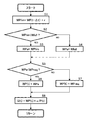
- FIG. 8 is a flowchart showing the calculation procedure of the pump flow rate command value Q by the controller 80. As shown in FIG. 8, when the controller 80 recognizes that the engine 22 is rotationally driven by the engine speed N, for example, the procedure of steps S1 to S8 in FIG. 8 is performed for a set time ⁇ t (for example, 0.1 s). The pump flow rate command value Q corresponding to the situation is repeatedly calculated and output to the pump regulator 43.
- ⁇ t for example, 0.1 s
- Step S1 When the procedure of FIG. 8 is started, the controller 80 inputs the power storage device information from the monitoring device 28, and calculates the allowable increase rate r of the pump absorption power according to the power storage device information by the increase rate calculation device 81.
- the calculated allowable increase rate r is added to the target pump power WP (t ⁇ t) of the hydraulic pump 41 calculated in the immediately preceding processing cycle by the limit power calculation device 82, and the minimum value selection device 85 as the limit pump power WPlim. Is output.
- step S2 the controller 80 determines whether the limit pump power WPlim calculated in step S1 is smaller than the outputable power Wfull calculated by the outputable power calculation device 84 based on the engine speed N. Determination is made by the value selection device 85. If the limited pump power WPlim according to the power storage device information is smaller than the outputtable power Wfull and the determination of step S2 is satisfied in the minimum value selection device 85, the controller 80 moves the procedure to step S3. On the other hand, when the limit pump power WPlim is equal to or greater than the output possible power Wfull and the determination is not satisfied in the minimum value selection device 85, the controller 80 shifts the procedure to step S4.
- step S3 the controller 80 sets the limit pump power WPlim, which is the smaller value, to the intermediate variable WPa.
- the controller 80 sets the output possible power Wfull, which is the smaller value, to the intermediate variable WPa.
- Steps S5-S7 the controller 80 determines whether or not the intermediate variable WPa calculated in step S3 or S4 is smaller than the required pump power WPreq calculated by the required power calculation device 83 based on the operation signal. To do. If the intermediate variable WPa is smaller than the required pump power WPreq and the determination is satisfied in the minimum value selection device 85, the controller 80 moves the procedure to step S6. Conversely, if the intermediate variable WPa is equal to or greater than the required pump power WPreq and the determination is not satisfied in the minimum value selection device 85, the controller 80 moves the procedure to step S7.
- step S6 the controller 80 sets the intermediate variable WPa, which is the smaller value, to the target pump power WP (t) of the current cycle.
- step S7 the controller 80 sets the requested pump power WPreq, which is the smaller value, to the target pump power WP (t).
- Step S8 When the procedure of step S6 or S7 is completed, the controller 80 moves the procedure to step S8, and uses the target pump power WP (t), the pump efficiency e and the current pump discharge pressure P (t) calculated in steps S2-S7. Then, the pump controller 86 calculates the pump flow rate command value Q (t) in the current cycle and outputs it to the pump regulator 43.
- the pump flow rate command value Q that is updated as needed for each cycle is output to the pump regulator 43, and the hydraulic pressure so that the pump absorption power approaches the target pump power WP (t).
- the discharge flow rate of the pump 41 is controlled.
- FIG. 9 is a diagram illustrating an example of changes over time in pump absorption power, pump discharge pressure, and pump discharge flow rate in the present embodiment.
- time t ⁇ b> 0 is an operation start time by the operation device 70.
- the limit pump power WPlim is selected as the target pump power WP by the minimum value selection device 85 because the power storage device 24 has a small amount of remaining power.
- the operation amount of the operation device 70 is the maximum operation amount, for example, the requested pump power WPreq for the hydraulic pump 41 rises rapidly as shown by the dotted line.
- the target pump power WP rises at a moderate increase rate compared to the requested pump power WPreq according to the power storage device information, and then the target pump power WP reaches the requested pump power WPreq.
- target pump powers WP1 and WP2 having different increase rates are illustrated.
- the target pump power WP1 catches up with the required pump power WPreq at time t2 (> t0), and the target pump power WP2 having a relatively low increase rate catches up with the requested pump power WPreq at time t3 (> t2).
- the difference between the two increases is due to the state of the power storage device 24. If the remaining amount of power storage is small, for example, when the target pump power WP1 is calculated, the target pump power WP2 is equal to the target pump power WP1 as shown in FIG. It is set at a slower rate of increase.
- the pump flow rate command value Q is set small even if the discharge pressure P (hydraulic load) of the hydraulic pump 41 is the same.
- Q1 and Q2 are pump flow rate command values calculated based on the target pump powers WP1 and WP2, respectively. In the case of the figure, the pump flow rate command value Q2 is calculated smaller than the pump flow rate command value Q1 from time t0 to t3.
- FIG. 10 is a PQ diagram in which the horizontal axis represents the discharge pressure and the vertical axis represents the flow rate.
- the dotted line in the figure represents an equal horsepower line, and the solid line represents a change in the pump flow rate command value Q.
- points A1 and B1 represent time t1
- points A2 and B2 represent time t2
- points A3 and B3 represent pump discharge pressure P and pump flow rate command value Q at time t3.
- the output (horsepower) increases toward the upper right. It can be seen that the output by the pump flow rate command value Q2 is suppressed from the output by the pump flow rate command value Q1 at the same time (t1, t2) until the time t3. Further, after the target pump power WP2 catches up with WP1 at time t3, the outputs by the pump flow rate commands Q1 and Q2 are the same.
- FIG. 11 is an explanatory diagram of the effect of this embodiment.
- Engine power WE is limited according to engine speed N from the viewpoint of engine stall and lag-down prevention. For this reason, for example, at the start of a sudden operation, even if the requested pump power WPreq suddenly rises and reaches the rated maximum output WEmax of the engine 22, the engine power WE can be increased only at a predetermined increase rate.
- the shortage of the engine power WE relative to the requested pump power WPreq at the start of movement can be supplemented by the power of the assist power generation motor 23.
- the power supply to the assist power generation motor 23 is not restricted by the state of the power storage device 24, for example, when the remaining amount of power storage is sufficient, the shortage of the engine power WE is assisted as shown in FIG.
- the power corresponding to the required pump power WPreq can be applied to the hydraulic pump 41 by making up for the power of the generator motor 23 (hatched portion in FIG. 11A).
- the engine power WE may not be compensated for by the power of the assist generator motor 23 with respect to the required pump power WPreq.
- the maximum value WPmax of the limit pump power WPlim (hereinafter referred to as the maximum limit pump power WPmax) is as shown in FIG.
- the maximum limit pump power WPmax is set lower than the rated maximum output WEmax of the engine 22. This is because if the maximum limit pump power WPmax is not suppressed, engine stall or lug-down can be performed when the remaining amount of power storage is exhausted and power is not added by the assist power generation motor 23.
- the target pump power WP is equal to the limit pump power WPlim
- the maximum value of the target pump power WP is equal to the maximum limit pump power WPmax. Therefore, if the maximum limited pump power WPmax is set lower than the rated maximum output WEmax, the power that can be output when the engine speed N increases after that cannot be output. For example, the target pump power WP (t1) at time t1 immediately after the start of operation can be made to follow the required pump power WPreq, but the target pump power WP (t2) reaches the maximum limit pump power WPmax at time t2.
- the target pump power WP (t3) remains at the maximum limited pump power WPmax and the rated maximum output WEmax is output even when the engine reaches the time t3 when the rated maximum output WEmax can be output by itself. Can not do it.
- the rated maximum output WEmax can be reached thereafter even under the restriction of power supply.
- the target pump power WP rises more slowly than the required pump power WPreq. Therefore, the maximum value of the target pump power WP is not excessively suppressed, and the engine power WE at the time of starting movement can be assisted by the power of the assist power generation motor 23 within a limited range.
- the target pump power WP (t1) at the time t1 immediately after the start of the operation is lower than that in the example of FIG. 11B, but the target pump has a higher rate of increase than the engine power WE.
- the power WP can be increased, and the target pump power WP (t3) can reach the rated maximum output WEmax at time t3.
- the allowable increase rate r when the allowable increase rate r is determined based on the remaining amount of stored electricity, there is an advantage that a decrease in the remaining amount of stored electricity can be suppressed.
- the target pump power WP can be flexibly set according to the situation, such as a region where power consumption suppression is prioritized over output decrease suppression in a region where the specified value a4 or less is applied. it can.
- the target pump power WP can be flexibly set according to the scene, such as the region, the region of the specified value a6 or more, in which the discharge suppression is suppressed rather than the output decrease suppression.
- the allowable increase rate r is calculated by the increase rate calculation device 81 according to the effective current or the temperature of the power storage device 24 instead of the effective power. It is good also as composition to do.
- the effective current can be obtained by the root mean square of the charge / discharge current of the set time based on the charge / discharge current input from the monitoring device 28.
- temperature information of the power storage device 24 measured by the temperature sensor of the monitoring device 28 can be used.
- the effective power or effective current may be input from the monitoring device 28 to the increase rate calculation device 81.
- FIG. 12 is a control block diagram relating to the pump flow rate control of the controller provided in the hybrid work machine according to the second embodiment of the present invention. This figure corresponds to FIG. 3 of the first embodiment.
- the controller 80A shown in FIG. 12 is different from the controller 80 shown in FIG. 3 in that the controller 80A further includes a maximum limit power calculation device 90 that calculates the maximum limit pump power WPmax (the maximum value of the limit pump power WPlim). It is.
- the other elements are the same as those of the controller 80 in FIG. 3, and the same reference numerals as those in the first embodiment are given in FIG.
- the relationship between the power storage device information and the maximum limit pump power WPmax is stored in the maximum limit power calculation device 90 in advance. Based on this relationship, the maximum limit power calculation device 90 calculates the maximum limit pump power WPmax according to the power storage device information input from the monitoring device 28, and outputs it to the minimum value selection device 85. In the minimum value selection device 85, the minimum value is selected from the limit pump power WPlim, the requested pump power WPreq, the output possible power Wfull, and the maximum limit pump power WPmax, and this is output to the pump control device 86 as the target pump power WP. Other configurations and operations of the present embodiment are the same as those of the first embodiment.
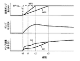
- FIG. 13 is a diagram showing an example of changes over time in pump absorption power, pump discharge pressure, and pump discharge flow rate in the present embodiment.
- the maximum limited pump power WPmax is suppressed according to the remaining amount of electricity stored.
- the limit pump power WPlim is output as the target pump power WP in the region where the limit pump power WPlim is equal to or less than the maximum limit pump power WPmax, and the limit pump power WPlim is the maximum limit pump power. In a region exceeding WPmax, maximum limited pump power WPmax is output as target pump power WP.
- the target pump power WP is set at a moderate increase rate with respect to the requested pump power WPreq in the present embodiment as in the first embodiment, The same effect as in the first embodiment can be obtained.
- the target pump power WP is set lower in the present embodiment than in the first embodiment as shown in FIG.
- the command value Q is also reduced. In this case, since the maximum limit pump power WPmax is lowered with a decrease in the remaining amount of power storage, there is an advantage that the continuous discharge amount of the power storage device 24 can be suppressed as compared with the first embodiment.
Abstract
電動モータへの給電が制限される状況でもポンプ吸収動力が過度に制限されることを抑制することができるハイブリッド式作業機械を提供する。 エンジン22と、エンジン22とトルク伝達可能に接続されたアシスト発電モータ23と、アシスト発電モータ23に給電する蓄電装置24と、蓄電装置24を監視して蓄電装置情報を取得する監視装置28と、エンジン22及びアシスト発電モータ23で駆動される油圧ポンプ41と、油圧ポンプ41の吐出流量を調整するポンプレギュレータ43とを備えたハイブリッド式作業機械において、ポンプ吸収動力について蓄電装置情報に応じた許容増加率rを演算する増加率演算装置81と、許容増加率rに基づいてポンプ吸収動力の制限値WPlimを演算する制限動力演算装置82と、制限ポンプ動力WPlimに応じて油圧ポンプ41の吐出流量を制御するポンプ制御装置86とを備える。
Description
本発明は、動力源としてエンジンの他に電動モータを備える油圧ショベルやホイールローダ等のハイブリッド式作業機械に関する。
エンジンの排気ガスの低減や省エネルギー化を目的としてエンジンに加えて発電モータを動力源とするハイブリッド式作業機械が知られている(特許文献1等参照)。この種のハイブリッド式作業機械では、エンジンと発電モータを同軸上に設け、発電モータとエンジンとで油圧ポンプを駆動し、油圧ポンプから吐出される圧油で油圧アクチュエータを駆動する。ポンプ吸収動力に対してエンジン動力が大きい場合には、余剰のエンジン動力で発電モータが駆動されて蓄電装置が充電される。ポンプ吸収動力に対してエンジン動力が小さい場合には、蓄電装置からの給電で発電モータを駆動してエンジン動力をアシストする。このようにして車体に要求される出力が発電モータで補われるため、エンジンの小型化により燃費が改善される。急操作時等のように油圧ポンプに要求される動力の急増時に、エンジン動力の不足分を発電モータの動力で補うものもある(特許文献2等参照)。
ハイブリッド式作業機械では、油圧アクチュエータの負荷が高い作業が連続すると蓄電残量の低下により発電モータで動力を出力することができなくなり、ラグダウンやエンストが発生する恐れがある。それに対し、特許文献1では、ポンプ吸収動力の最大値を蓄電残量に応じて制限することが開示されている。これはラグダウンやエンストの抑制に効果的である。
しかし、特許文献2のように負荷急増時にエンジン出力の不足分を補うために発電モータで動力を出力する場合、蓄電残量が足りない場合には発電モータで補える動力に限りがあるため、エンスト等を起こさないように動き出し時等にポンプ吸収動力が低く設定されてしまう。ポンプ吸収動力が制限された状態では、その後の作業において機体本来の性能が発揮できない。
本発明の目的は、電動モータへの給電が制限される状況でもポンプ吸収動力が過度に制限されることを抑制することができるハイブリッド式作業機械を提供することである。
上記目的を達成するために、本発明は、エンジンと、前記エンジンとトルク伝達可能に接続された電動モータと、前記電動モータに給電する蓄電装置と、前記蓄電装置の状態を監視して蓄電装置情報を取得する監視装置と、前記エンジン及び前記電動モータの動力で駆動される油圧ポンプと、前記油圧ポンプの吐出流量を調整するポンプレギュレータとを備えたハイブリッド式作業機械において、前記油圧ポンプの吸収動力であるポンプ吸収動力について前記蓄電装置情報に応じた許容増加率を演算する増加率演算装置と、前記許容増加率に基づいて前記ポンプ吸収動力の制限値である制限ポンプ動力を演算する制限動力演算装置と、前記制限ポンプ動力に応じて前記ポンプレギュレータに対して指令信号を出力し前記油圧ポンプの吐出流量を制御するポンプ制御装置とを備えたことを特徴とする。
本発明によれば、電動モータへの給電が制限される状況でもポンプ吸収動力が過度に制限されることを抑制することができる。
以下に図面を用いて本発明の実施の形態を説明する。
(第1実施形態)
1.ハイブリッド式作業機械
図1は本発明の第1実施形態に係るハイブリッド式作業機械の一例であるハイブリッド式油圧ショベルの一部透視側面図である。但し、ハイブリッド式油圧ショベルは一適用例であり、ハイブリッド式のホイールローダ等、他のハイブリッド式作業機械にも本発明は適用可能である。図1に示したハイブリッド式油圧ショベルは、走行体10、走行体10上に旋回可能に設けた旋回体20、及び旋回体20に設けたショベル機構(フロント作業機)30を備えている。
1.ハイブリッド式作業機械
図1は本発明の第1実施形態に係るハイブリッド式作業機械の一例であるハイブリッド式油圧ショベルの一部透視側面図である。但し、ハイブリッド式油圧ショベルは一適用例であり、ハイブリッド式のホイールローダ等、他のハイブリッド式作業機械にも本発明は適用可能である。図1に示したハイブリッド式油圧ショベルは、走行体10、走行体10上に旋回可能に設けた旋回体20、及び旋回体20に設けたショベル機構(フロント作業機)30を備えている。
走行体10は、左右一対のクローラ11a,11b及びクローラフレーム12a,12b、左右のクローラ11a,11bをそれぞれ駆動する走行用油圧モータ13,14、並びに走行用油圧モータ13,14の減速機等を備えている。クローラ11a,11b及びクローラフレーム12a,12bについてはそれぞれ左側のもののみ図1に図示する。
旋回体20は運転室やエンジン室等を含み、旋回フレーム21を介してクローラフレーム12a,12bの上部に搭載されている。運転室には油圧アクチュエータ(後述)の動作を指示する操作装置70(図2参照)等が備わっている。旋回フレーム21は旋回輪を介してクローラフレーム12a,12bの上部に鉛直軸を中心に旋回可能に設けてある。特に図示していないが、旋回輪はクローラフレーム12a,12bに接続した内輪と旋回フレーム21に接続した外輪を備えていて、内輪に対して外輪が回転する構成である。旋回フレーム21上には旋回用発電モータ25及び旋回用油圧モータ27が設けられている。旋回用発電モータ25は旋回用油圧モータ27と共に旋回輪の外輪に支持されていて、減速機26を介して内輪の内歯車に出力軸を噛合させている。旋回用油圧モータ27は旋回用発電モータ25と同軸に設けられている。また、旋回用発電モータ25には蓄電装置24が接続されていて、蓄電装置24からの給電により旋回用発電モータ25が駆動される。この構成より旋回用油圧モータ27及び旋回用発電モータ25の駆動力が減速機26を介して旋回輪に伝達され、走行体10に対して旋回フレーム21と共に旋回体20が旋回する。
ショベル機構30は、ブーム31、アーム33、バケット35を備えた多関節構造のフロント作業機である。ブーム31は旋回体20の旋回フレーム21に上下方向に回動動可能に連結されている。アーム33はブーム31の先端部に前後方向に回動可能に連結されている。バケット35はアーム33の先端部に回動可能に連結されている。そして、ブーム31、アーム33及びバケット35は、ブームシリンダ32、アームシリンダ34及びバケットシリンダ36でそれぞれ駆動される。ブームシリンダ32、アームシリンダ34及びバケットシリンダ36は油圧シリンダである。
2.駆動システム
上記旋回フレーム21上には、各種アクチュエータを駆動するための駆動システムが搭載されている。この駆動システムには、油圧システム40、電動システム及びコントローラ80(図2参照)が含まれる。油圧システム40は、走行用油圧モータ13,14、旋回用油圧モータ27、ブームシリンダ32、アームシリンダ34、バケットシリンダ36等の油圧アクチュエータを駆動する装置である。以下、走行用油圧モータ13,14、旋回用油圧モータ27、ブームシリンダ32、アームシリンダ34、バケットシリンダ36等を総称して油圧アクチュエータと適宜記載する。電動システムは、旋回用発電モータ25の他、後述するアシスト発電モータ23等の電動アクチュエータを駆動する装置である。油圧システム40及び電動システムを制御するのがコントローラ80である。駆動システムの模式図を図2に示す。
上記旋回フレーム21上には、各種アクチュエータを駆動するための駆動システムが搭載されている。この駆動システムには、油圧システム40、電動システム及びコントローラ80(図2参照)が含まれる。油圧システム40は、走行用油圧モータ13,14、旋回用油圧モータ27、ブームシリンダ32、アームシリンダ34、バケットシリンダ36等の油圧アクチュエータを駆動する装置である。以下、走行用油圧モータ13,14、旋回用油圧モータ27、ブームシリンダ32、アームシリンダ34、バケットシリンダ36等を総称して油圧アクチュエータと適宜記載する。電動システムは、旋回用発電モータ25の他、後述するアシスト発電モータ23等の電動アクチュエータを駆動する装置である。油圧システム40及び電動システムを制御するのがコントローラ80である。駆動システムの模式図を図2に示す。
・油圧システム
図2に示したように、油圧システム40は、油圧ポンプ41、ポンプレギュレータ43及びコントロールバルブ42を含む。油圧ポンプ41は油圧を発生する可変容量型の油圧ポンプであり、エンジン22が出力する動力によって駆動されて、油圧アクチュエータを駆動する圧油を吐出する。エンジン22には回転数センサが設けられており、回転数センサでエンジン回転数Nが検出される。油圧ポンプ41の吐出管路には吐出圧センサ44が設けられており、吐出圧センサ44で油圧ポンプ41の吐出圧Pが検出される。コントロールバルブ42は各油圧アクチュエータを駆動制御するバルブユニットであり、運転室内にある操作装置70からの操作信号(本実施形態では油圧パイロット信号)で対応するスプールを動作させて、油圧ポンプ41から各油圧アクチュエータにそれぞれ供給される圧油の流量と方向を制御する。操作装置70からの操作信号はまた、電気信号に変換されてコントローラ80にも入力される。ポンプレギュレータ43は、コントローラ80からの信号に基づいて油圧ポンプ41の押し退け容積(吐出流量)を調整する。
図2に示したように、油圧システム40は、油圧ポンプ41、ポンプレギュレータ43及びコントロールバルブ42を含む。油圧ポンプ41は油圧を発生する可変容量型の油圧ポンプであり、エンジン22が出力する動力によって駆動されて、油圧アクチュエータを駆動する圧油を吐出する。エンジン22には回転数センサが設けられており、回転数センサでエンジン回転数Nが検出される。油圧ポンプ41の吐出管路には吐出圧センサ44が設けられており、吐出圧センサ44で油圧ポンプ41の吐出圧Pが検出される。コントロールバルブ42は各油圧アクチュエータを駆動制御するバルブユニットであり、運転室内にある操作装置70からの操作信号(本実施形態では油圧パイロット信号)で対応するスプールを動作させて、油圧ポンプ41から各油圧アクチュエータにそれぞれ供給される圧油の流量と方向を制御する。操作装置70からの操作信号はまた、電気信号に変換されてコントローラ80にも入力される。ポンプレギュレータ43は、コントローラ80からの信号に基づいて油圧ポンプ41の押し退け容積(吐出流量)を調整する。
・電動システム
電動システムは、上述した蓄電装置24の他、インバータ50、アシスト発電モータ23及び蓄電装置24を含んでいる。アシスト発電モータ23は、エンジン22とトルク伝達可能に接続された電動モータであり、蓄電装置24からの給電により駆動されてエンジン22と共に油圧ポンプ41を駆動する。本実施形態ではアシスト発電モータ23に発電機としても機能する発電モータを用いた場合を例示するが、発電機能のない単なる電動モータを用いても良い。インバータ50はアシスト発電モータ23の他、旋回用発電モータ25(図1参照)と電気的に接続しており、またコンタクタ(不図示)を介して蓄電装置24に接続している。アシスト発電モータ23及び旋回用発電モータ25の駆動状態(力行するか回生するか)は、コントローラ80からの指令に従ってインバータ50によって制御される。蓄電装置24は、インバータ50からの信号に基づき、アシスト発電モータ23及び旋回用発電モータ25の駆動状態によって充放電される。蓄電装置24には、当該蓄電装置24の充電残量(SOC)、充放電電力量、充放電電流量、実効電力、温度等を監視して、これら蓄電装置情報を取得する監視装置28が設けられている。
電動システムは、上述した蓄電装置24の他、インバータ50、アシスト発電モータ23及び蓄電装置24を含んでいる。アシスト発電モータ23は、エンジン22とトルク伝達可能に接続された電動モータであり、蓄電装置24からの給電により駆動されてエンジン22と共に油圧ポンプ41を駆動する。本実施形態ではアシスト発電モータ23に発電機としても機能する発電モータを用いた場合を例示するが、発電機能のない単なる電動モータを用いても良い。インバータ50はアシスト発電モータ23の他、旋回用発電モータ25(図1参照)と電気的に接続しており、またコンタクタ(不図示)を介して蓄電装置24に接続している。アシスト発電モータ23及び旋回用発電モータ25の駆動状態(力行するか回生するか)は、コントローラ80からの指令に従ってインバータ50によって制御される。蓄電装置24は、インバータ50からの信号に基づき、アシスト発電モータ23及び旋回用発電モータ25の駆動状態によって充放電される。蓄電装置24には、当該蓄電装置24の充電残量(SOC)、充放電電力量、充放電電流量、実効電力、温度等を監視して、これら蓄電装置情報を取得する監視装置28が設けられている。
・コントローラ
コントローラ80には、吐出圧センサ44で検出された油圧ポンプ41の吐出圧P、回転数センサで検出されたエンジン回転数N、操作装置70からの操作信号、及び監視装置28からの蓄電装置情報が入力される。コントローラ80は、これら種入力信号を基に、エンジン22の燃料噴射装置、ポンプレギュレータ43、インバータ50等に対する制御指令を生成し、アシスト発電モータ23及び旋回用発電モータ25の力行及び回生の切り換え並びに出力制御、油圧ポンプ41の吐出流量制御、エンジン22の出力制御等を実行する。
コントローラ80には、吐出圧センサ44で検出された油圧ポンプ41の吐出圧P、回転数センサで検出されたエンジン回転数N、操作装置70からの操作信号、及び監視装置28からの蓄電装置情報が入力される。コントローラ80は、これら種入力信号を基に、エンジン22の燃料噴射装置、ポンプレギュレータ43、インバータ50等に対する制御指令を生成し、アシスト発電モータ23及び旋回用発電モータ25の力行及び回生の切り換え並びに出力制御、油圧ポンプ41の吐出流量制御、エンジン22の出力制御等を実行する。
図3はコントローラ80のポンプ流量制御に係る制御ブロック図である。この図に示したコントローラ80は、増加率演算装置81、制限動力演算装置82、要求動力演算装置83、出力可能動力演算装置84、最小値選択装置85、ポンプ制御装置86及び記憶装置87等を備えている。
増加率演算装置81は、駆動システムが出力する動力のうち油圧ポンプ41で消費される動力(以下、ポンプ吸収動力と記載する)の許容増加率rを演算する機能部である。この許容増加率rは、蓄電装置24の状態によって定まる値であり、エンジン22の出力動力WE(以下、エンジン動力WEと記載する)の増加率よりは高い増加率でポンプ吸収動力が増加するように、操作装置70の操作信号に応じたポンプ吸収動力の要求値WPreq(以下、要求ポンプ動力WPreqと記載する)に関わらず蓄電装置情報に応じて設定される。増加率演算装置81には蓄電装置情報(蓄電残量、充放電電流量、実効電力、蓄電装置温度等の少なくとも1つ)と許容増加率rとの関係が予め格納されており、増加率演算装置81では、この関係に基づき、監視装置28から入力された蓄電装置情報に応じた許容増加率rが演算される。
ここで、図4は増加率演算装置81の一例を示すブロック図である。この図に例示した増加率演算装置81aは、蓄電装置情報として蓄電残量を監視装置28から入力する。許容増加率rの演算の基礎として蓄電残量を入力する場合、増加率演算装置81aには蓄電残量が少ないほど許容増加率rが小さくなる関係が格納され、入力された蓄電残量が小さいほど許容増加率rは小さく演算される。本実施形態では、蓄電残量が設定の規定値a1以下の領域において、蓄電残量が規定値a1から減少するのに正比例して許容増加率rも減少するようにしてある。
図5は増加率演算装置81の他の例を示すブロック図である。この図に例示した増加率演算装置81bは、蓄電装置情報として蓄電装置24の充放電電力を監視装置28から入力する。許容増加率rの演算の基礎として充放電電力を入力する場合、増加率演算装置81bには実効電力が大きいほど許容増加率rが小さくなる関係が格納される。実効電力は、蓄電装置24の設定時間の充放電電力の二乗平均平方根で求められる。例えば設定時間を100秒間とすると、100秒前から現在までの蓄電装置24の充放電電力の二乗平均を求め、その平方根を採ることで実効電力を基得ることができる。実効電力の演算は、監視装置28で実行されない場合は増加率演算装置81bで実行するようにしても良い。増加率演算装置81bには実効電力が大きいほど許容増加率rが小さくなる関係が格納され、求めた実効電力が大きいほど許容増加率rは小さく演算される。本実施形態では、実効電力が設定の規定値a2以上の領域において、実効電力が規定値a2から増加するのに正比例して許容増加率rが減少するようにしてある。
図6は増加率演算装置81の更に他の例を示すブロック図である。この図に例示した増加率演算装置81cは、蓄電装置情報として蓄電装置24の蓄電残量を監視装置28から入力する。図6の増加率演算装置81cに格納された蓄電残量と許容増加率rの関係は、蓄電残量が少ないほど許容増加率rが小さくなる点で図4の例と同様であるが、蓄電残量によって許容増加率rの増減率に差がある点で相違する。図6の例では、蓄電残量が規定値a3からa4(<a3)にかけて減少する際には許容増加率rが一定割合α1で減少していき、規定値a4を下回って減少する際には許容増加率rがより大きな一定割合α2(>α1)で減少する。蓄電残量によって許容増加率rに差を付ける場合、蓄電残量と許容増加率rの関係線を蓄電残量が小さいほど許容増加率rの減少率が大きくなるような曲線に設定することも考えられる。
図7は増加率演算装置81の更に他の例を示すブロック図である。この図に例示した増加率演算装置81dは、蓄電装置情報として蓄電装置24の充放電電力を監視装置28から入力する。図7の増加率演算装置81dに格納された実効電力と許容増加率rの関係は、実効電力が大きいほど許容増加率rが小さくなる点で図5の例と同様であるが、実効電力によって許容増加率rの増減率に差がある点で相違する。図7の例では、実効電力が規定値a5からa6(>a5)にかけて増加する際には許容増加率rが一定割合α3で減少していき、規定値a6を超えて増加する際には許容増加率rがより大きな一定割合α4(>α3)で減少する。実効電力によって許容増加率rに差を付ける場合、実効電力と許容増加率rの関係線を実効電力が大きいほど許容増加率rの減少率が大きくなるような曲線に設定することも考えられる。
図3に戻り、制限動力演算装置82は、蓄電装置情報に応じた許容増加率rに基づいてポンプ吸収動力の制限値WPlim(以下、制限ポンプ動力WPlimと記載する)を演算する。本実施形態では制限動力演算装置82に加算器を用いている。制限ポンプ動力WPlimは、制限動力演算装置82において、前回(1つ前のサイクルで)最小値選択装置58で演算された目標ポンプ動力WP(後述)に、今回(現在のサイクルで)増加率演算装置81で演算された許容増加率rを加算することによって演算される。制限ポンプ動力WPlimは、コントローラ80のサイクル処理の進捗に伴って許容増加率rで経時的に変化していく。
要求動力演算装置83は、前述した要求ポンプ動力WPreqを演算する機能部である。要求動力演算装置83には操作装置70の操作量と要求ポンプ動力WPreqとの関係が予め格納されており、要求動力演算装置83では、この関係に基づき、操作装置70から入力された操作信号に応じた要求ポンプ動力WPreqが演算される。
出力可能動力演算装置84は、出力可能動力Wfull(以下、出力可能動力Wfull)を演算する機能部である。出力可能動力Wfullとは、その時点で(現在のサイクルにおいて)エンジン22及びアシスト発電モータ23によって駆動システムがエンストやラグダウン等することなく出力することができる最大動力である。この出力可能動力Wfullは、エンジン回転数Nによってエンジン22のトルクカーブが変わることからエンジン回転数Nに応じて値が変化するが、その演算に蓄電装置情報は考慮されない。出力可能動力演算装置84にはエンジン回転数Nと出力可能動力Wfullとの関係が予め格納されており、出力可能動力演算装置84では、この関係に基づき、エンジン回転数Nに応じた出力可能動力Wfullが演算される。
最小値選択装置85は、制限ポンプ動力WPlim、要求ポンプ動力WPreq及び出力可能動力Wfullを入力し、3つの入力値から選択した最小値を現在のサイクルにおけるポンプ吸収動力の目標値WP(以下、目標ポンプ動力WPと記載する)として出力する。この目標ポンプ動力WPは、前述したように次回(1つ後のサイクル)の制限ポンプ動力WPlimの演算のために制限動力演算装置82にも出力される。
ポンプ制御装置86は、目標ポンプ動力WPに基づいてポンプレギュレータ43を制御する機能部である。このポンプ制御装置86には乗算器88と除算器89が含まれている。ポンプ制御装置86においては、最小値選択装置85から入力された目標ポンプ動力WPに対し、記憶装置87から読み出された油圧ポンプ41のポンプ効率eを乗算器88で掛け、更に除算器89において吐出圧センサ44から入力された油圧ポンプ41の現在のサイクルの吐出圧Pで割ることで、ポンプ流量指令値Qが算出される。コントローラ80は、このポンプ流量指令値Qをポンプレギュレータ43に出力する。これにより、油圧ポンプ41の吸収動力が目標ポンプ動力WPになるように、油圧ポンプ41の吐出流量(容積)が制御される。
3.ポンプ流量指令値Qの演算手順
図8はコントローラ80によるポンプ流量指令値Qの演算手順を表したフローチャートである。図8に示したように、コントローラ80は、例えばエンジン回転数Nによりエンジン22が回転駆動中であることを認識すると、図8のステップS1-S8の手順を設定時間Δt(例えば0.1s)のサイクルで実行し、状況に応じたポンプ流量指令値Qを繰り返し演算しポンプレギュレータ43に出力する。
図8はコントローラ80によるポンプ流量指令値Qの演算手順を表したフローチャートである。図8に示したように、コントローラ80は、例えばエンジン回転数Nによりエンジン22が回転駆動中であることを認識すると、図8のステップS1-S8の手順を設定時間Δt(例えば0.1s)のサイクルで実行し、状況に応じたポンプ流量指令値Qを繰り返し演算しポンプレギュレータ43に出力する。
・ステップS1
図8の手順を開始すると、コントローラ80は、監視装置28から蓄電装置情報を入力し、蓄電装置情報に応じたポンプ吸収動力の許容増加率rを増加率演算装置81で演算する。演算された許容増加率rは1つ前の処理サイクルで演算した油圧ポンプ41の目標ポンプ動力WP(t-Δt)に制限動力演算装置82で加算され、制限ポンプ動力WPlimとして最小値選択装置85に出力される。
図8の手順を開始すると、コントローラ80は、監視装置28から蓄電装置情報を入力し、蓄電装置情報に応じたポンプ吸収動力の許容増加率rを増加率演算装置81で演算する。演算された許容増加率rは1つ前の処理サイクルで演算した油圧ポンプ41の目標ポンプ動力WP(t-Δt)に制限動力演算装置82で加算され、制限ポンプ動力WPlimとして最小値選択装置85に出力される。
・ステップS2-S4
続くステップS2に手順を移すと、コントローラ80は、ステップS1で算出した制限ポンプ動力WPlimが、エンジン回転数Nを基に出力可能動力演算装置84で演算した出力可能動力Wfullより小さいかどうかを最小値選択装置85で判断する。コントローラ80は、蓄電装置情報に応じた制限ポンプ動力WPlimが出力可能動力Wfullよりも小さく、最小値選択装置85においてステップS2の判定が満たされた場合にはステップS3に手順を移す。反対に、コントローラ80は、制限ポンプ動力WPlimが出力可能動力Wfull以上で、最小値選択装置85において判定が満たされない場合にはステップS4に手順を移す。ステップS3に進んだ場合、コントローラ80は、小さい方の値である制限ポンプ動力WPlimを中間変数WPaに設定する。一方、ステップS4に進んだ場合、コントローラ80は、小さい方の値である出力可能動力Wfullを中間変数WPaに設定する。
続くステップS2に手順を移すと、コントローラ80は、ステップS1で算出した制限ポンプ動力WPlimが、エンジン回転数Nを基に出力可能動力演算装置84で演算した出力可能動力Wfullより小さいかどうかを最小値選択装置85で判断する。コントローラ80は、蓄電装置情報に応じた制限ポンプ動力WPlimが出力可能動力Wfullよりも小さく、最小値選択装置85においてステップS2の判定が満たされた場合にはステップS3に手順を移す。反対に、コントローラ80は、制限ポンプ動力WPlimが出力可能動力Wfull以上で、最小値選択装置85において判定が満たされない場合にはステップS4に手順を移す。ステップS3に進んだ場合、コントローラ80は、小さい方の値である制限ポンプ動力WPlimを中間変数WPaに設定する。一方、ステップS4に進んだ場合、コントローラ80は、小さい方の値である出力可能動力Wfullを中間変数WPaに設定する。
・ステップS5-S7
続くステップS5では、コントローラ80は、ステップS3又はS4で計算した中間変数WPaが、操作信号を基に要求動力演算装置83で演算した要求ポンプ動力WPreqより小さいかどうかを最小値選択装置85で判断する。コントローラ80は、中間変数WPaが要求ポンプ動力WPreqよりも小さく、最小値選択装置85において判定が満たされる場合にはステップS6に手順を移す。反対に、コントローラ80は、中間変数WPaが要求ポンプ動力WPreq以上で、最小値選択装置85において判定が満たされない場合にはステップS7に手順を移す。ステップS6に進んだ場合、コントローラ80は、小さい方の値である中間変数WPaを現在のサイクルの目標ポンプ動力WP(t)に設定する。一方、ステップS7に進んだ場合、コントローラ80は、小さい方の値である要求ポンプ動力WPreqを目標ポンプ動力WP(t)に設定する。ステップS2-S7の処理により、制限ポンプ動力WPlim、要求ポンプ動力WPreq及び出力可能動力Wfullの最小値が目標ポンプ動力WP(t)に設定される。
続くステップS5では、コントローラ80は、ステップS3又はS4で計算した中間変数WPaが、操作信号を基に要求動力演算装置83で演算した要求ポンプ動力WPreqより小さいかどうかを最小値選択装置85で判断する。コントローラ80は、中間変数WPaが要求ポンプ動力WPreqよりも小さく、最小値選択装置85において判定が満たされる場合にはステップS6に手順を移す。反対に、コントローラ80は、中間変数WPaが要求ポンプ動力WPreq以上で、最小値選択装置85において判定が満たされない場合にはステップS7に手順を移す。ステップS6に進んだ場合、コントローラ80は、小さい方の値である中間変数WPaを現在のサイクルの目標ポンプ動力WP(t)に設定する。一方、ステップS7に進んだ場合、コントローラ80は、小さい方の値である要求ポンプ動力WPreqを目標ポンプ動力WP(t)に設定する。ステップS2-S7の処理により、制限ポンプ動力WPlim、要求ポンプ動力WPreq及び出力可能動力Wfullの最小値が目標ポンプ動力WP(t)に設定される。
・ステップS8
ステップS6又はS7の手順を終えたら、コントローラ80はステップS8に手順を移し、ステップS2-S7で演算した目標ポンプ動力WP(t)、ポンプ効率e及び現在のポンプ吐出圧P(t)を用いてポンプ制御装置86で現在のサイクルにおけるポンプ流量指令値Q(t)を算出し、ポンプレギュレータ43に出力する。
ステップS6又はS7の手順を終えたら、コントローラ80はステップS8に手順を移し、ステップS2-S7で演算した目標ポンプ動力WP(t)、ポンプ効率e及び現在のポンプ吐出圧P(t)を用いてポンプ制御装置86で現在のサイクルにおけるポンプ流量指令値Q(t)を算出し、ポンプレギュレータ43に出力する。
以上の手順を設定時間Δtで繰り返し実行することで、サイクル毎に随時更新されるポンプ流量指令値Qがポンプレギュレータ43に出力され、ポンプ吸収動力が目標ポンプ動力WP(t)に近づくように油圧ポンプ41の吐出流量が制御される。
4.目標ポンプ動力の挙動
図9は本実施形態におけるポンプ吸収動力、ポンプ吐出圧及びポンプ吐出流量の経時的変化の一例を示す図である。図9において時刻t0は操作装置70による操作開始時刻である。また、蓄電装置24の蓄電残量が少ない等の理由により最小値選択装置85で目標ポンプ動力WPとして制限ポンプ動力WPlimが選択されるものとする。
図9は本実施形態におけるポンプ吸収動力、ポンプ吐出圧及びポンプ吐出流量の経時的変化の一例を示す図である。図9において時刻t0は操作装置70による操作開始時刻である。また、蓄電装置24の蓄電残量が少ない等の理由により最小値選択装置85で目標ポンプ動力WPとして制限ポンプ動力WPlimが選択されるものとする。
操作装置70の操作量が例えば最大操作量であるとすると、油圧ポンプ41に対する要求ポンプ動力WPreqは点線に示したように急激に立ち上がる。それに対し、本実施形態においては、蓄電装置情報に応じて要求ポンプ動力WPreqに比べて緩やかな増加率で目標ポンプ動力WPが立ち上がり、その後目標ポンプ動力WPが要求ポンプ動力WPreqに到達する。同図では増加率の異なる目標ポンプ動力WP1,WP2を例示している。目標ポンプ動力WP1は時刻t2(>t0)で、相対して増加率が低い目標ポンプ動力WP2は時刻t3(>t2)でそれぞれ要求ポンプ動力WPreqに追い付く。両者の増加率の違いは蓄電装置24の状態に起因しており、目標ポンプ動力WP1の演算時に相対して例えば蓄電残量が少ない場合、同図のように目標ポンプ動力WP2は目標ポンプ動力WP1よりも緩やかな増加率で設定される。目標ポンプ動力WPが小さい場合、油圧ポンプ41の吐出圧P(油圧負荷)が同じでもポンプ流量指令値Qは小さく設定される。Q1,Q2はそれぞれ目標ポンプ動力WP1,WP2に基づいて演算されたポンプ流量指令値である。同図の場合、ポンプ流量指令値Q2はポンプ流量指令値Q1に対して時刻t0からt3にかけて小さく演算される。
図10は図9の例を横軸に吐出圧、縦軸に流量をとって表したPQ線図である。図中の点線は等馬力線を、実線はポンプ流量指令値Qの変化を表している。図中の点A1,B1は図9の時刻t1、点A2,B2は時刻t2、点A3,B3は時刻t3におけるポンプ吐出圧P及びポンプ流量指令値Qを表す点である。この図では右上に行くほど出力(馬力)が大きくなる。時刻t3に至るまでの間、同時刻(t1,t2)ではポンプ流量指令値Q2による出力がポンプ流量指令値Q1による出力に対して抑えられることが分かる。また、時刻t3で目標ポンプ動力WP2がWP1に追い付いて以降、ポンプ流量指令Q1,Q2による出力は同一となる。
5.効果
図11は本実施形態の効果の説明図である。エンジン動力WEはエンストやラグダウン防止の観点からエンジン回転数Nに応じて制限される。そのため、例えば急操作による動き出し時には、要求ポンプ動力WPreqが急激に立ち上がってエンジン22の定格最大出力WEmaxに到達しても、エンジン動力WEについては所定の増加率でしか増加させることができない。それに対し、本実施形態のようなハイブリッド式作業機械の場合、動き出し時の要求ポンプ動力WPreqに対するエンジン動力WEの不足分をアシスト発電モータ23の動力で補うことができる。このとき、例えば蓄電残量が十分にある場合のように蓄電装置24の状態によってアシスト発電モータ23に対する給電が制約されない場合、図11(a)に示すようにエンジン動力WEの不足分相当をアシスト発電モータ23の動力(図11(a)におけるハッチング部分)で補い、要求ポンプ動力WPreq相当の動力を油圧ポンプ41に対して与えることができる。
図11は本実施形態の効果の説明図である。エンジン動力WEはエンストやラグダウン防止の観点からエンジン回転数Nに応じて制限される。そのため、例えば急操作による動き出し時には、要求ポンプ動力WPreqが急激に立ち上がってエンジン22の定格最大出力WEmaxに到達しても、エンジン動力WEについては所定の増加率でしか増加させることができない。それに対し、本実施形態のようなハイブリッド式作業機械の場合、動き出し時の要求ポンプ動力WPreqに対するエンジン動力WEの不足分をアシスト発電モータ23の動力で補うことができる。このとき、例えば蓄電残量が十分にある場合のように蓄電装置24の状態によってアシスト発電モータ23に対する給電が制約されない場合、図11(a)に示すようにエンジン動力WEの不足分相当をアシスト発電モータ23の動力(図11(a)におけるハッチング部分)で補い、要求ポンプ動力WPreq相当の動力を油圧ポンプ41に対して与えることができる。
しかし、蓄電装置24の状態によっては要求ポンプ動力WPreqに対するエンジン動力WEの不足分をアシスト発電モータ23の動力で補いきれない場合もある。この場合、目標ポンプ動力WPを要求ポンプ動力WPreqに追従させて立ち上げると、制限ポンプ動力WPlimの最大値WPmax(以下、最大制限ポンプ動力WPmaxと記載する)は、図11(b)のように必然的にエンジン22の定格最大出力WEmaxよりも低く設定される。最大制限ポンプ動力WPmaxを抑えなければ、蓄電残量が尽きてアシスト発電モータ23による動力付加がなくなった際にエンストやラグダウンをし得るからである。ここでは目標ポンプ動力WPが制限ポンプ動力WPlimに等しくなる例を説明しているので、目標ポンプ動力WPの最大値は最大制限ポンプ動力WPmaxに等しい。従って、定格最大出力WEmaxよりも最大制限ポンプ動力WPmaxが低く設定されると、本来であればその後エンジン回転数Nが上昇した時に出せる動力が出力できなくなってしまう。例えば操作開始直後の時刻t1における目標ポンプ動力WP(t1)を要求ポンプ動力WPreqに追従させることはできるが、時刻t2で目標ポンプ動力WP(t2)は最大制限ポンプ動力WPmaxに達してしまう。その結果、本来であればその後エンジン単独で定格最大出力WEmaxが出せる筈の時刻t3になっても、目標ポンプ動力WP(t3)は最大制限ポンプ動力WPmaxのままであり、定格最大出力WEmaxを出力することができない。
それに対し、本実施形態においては、アシスト発電モータ23に対する給電が制限される場合には、図11(c)に示したように、給電の制約下でもその後定格最大出力WEmaxまで到達し得るように要求ポンプ動力WPreqよりも緩やかに目標ポンプ動力WPが立ち上がる。従って、目標ポンプ動力WPの最大値が過度に抑えられることがなく、制約の範囲で動き出し時のエンジン動力WEをアシスト発電モータ23の動力でアシストすることができる。図11(c)の例の場合、操作開始直後の時刻t1における目標ポンプ動力WP(t1)は図11(b)の例に比べて低くなるが、エンジン動力WEよりも高い増加率で目標ポンプ動力WPを上げていくことができ、時刻t3には目標ポンプ動力WP(t3)は定格最大出力WEmaxに到達し得る。
以上のように、本実施形態によれば、アシスト発電モータ23への給電が制限される状況でも、ポンプ吸収動力が過度に制限されることを抑制することができ、作業効率の低下を抑制することができる。
また、図4に示したように蓄電残量に基づいて許容増加率rを決定する場合、蓄電残量の減少を抑制することができるメリットがある。加えて図6のように蓄電残量によって許容増加率rの減少率に差を付ける場合、例えば同図の規定値a3-a4の領域は電力消費抑制の必要性はあるものの出力低下抑制が優先される領域、規定値a4以下の領域は出力低下抑制よりも電力消費抑制が優先される領域といったように、蓄電残量に応じて目標ポンプ動力WPの設定を場面に応じて柔軟にすることができる。
また、短時間の急激な充放電は蓄電装置24の劣化を進行させ得るが、図5に示したように実効電力を許容増加率rの演算の基礎とし、実効電力が大きく放電が急激な場合に許容増加率rを抑えることで、蓄電装置24の保護及び長寿命化にも寄与し得る。加えて図7のように実効電力によって許容増加率rの減少率に差を付ける場合、例えば同図の規定値a5-a6の領域は放電抑制の必要性はあるものの出力低下抑制が優先される領域、規定値a6以上の領域は出力低下抑制よりも放電抑制が抑制される領域といったように、実効電力に応じて目標ポンプ動力WPの設定を場面に応じて柔軟にすることができる。なお、蓄電装置24の使用強度を加味して目標ポンプ動力WPを決定する観点では、実効電力の代わりに実効電流や蓄電装置24の温度に応じて増加率演算装置81で許容増加率rを演算する構成としても良い。実効電流は、監視装置28から入力される充放電電流を基に、設定時間の充放電電流の二乗平均平方根で求めることができる。蓄電装置24の温度は監視装置28の温度センサで計測された蓄電装置24の温度情報を用いることができる。また、監視装置28で実効電力や実効電流の測定又は演算ができる場合には、実効電力や実効電流は監視装置28から増加率演算装置81に入力されるようにしても良い。
(第2実施形態)
図12は本発明の第2実施形態に係るハイブリッド式作業機械に備えられたコントローラのポンプ流量制御に係る制御ブロック図である。この図は第1実施形態の図3に対応している。図12に示したコントローラ80Aが図3のコントローラ80と相違する点は、前述した最大制限ポンプ動力WPmax(制限ポンプ動力WPlimの最大値)を演算する最大制限動力演算装置90を更に備えている点である。それ以外の要素は図3のコントローラ80と同様であり、図12において第1実施形態と同符号を付して説明を省略する。
図12は本発明の第2実施形態に係るハイブリッド式作業機械に備えられたコントローラのポンプ流量制御に係る制御ブロック図である。この図は第1実施形態の図3に対応している。図12に示したコントローラ80Aが図3のコントローラ80と相違する点は、前述した最大制限ポンプ動力WPmax(制限ポンプ動力WPlimの最大値)を演算する最大制限動力演算装置90を更に備えている点である。それ以外の要素は図3のコントローラ80と同様であり、図12において第1実施形態と同符号を付して説明を省略する。
最大制限動力演算装置90には蓄電装置情報と最大制限ポンプ動力WPmaxとの関係が予め格納されている。最大制限動力演算装置90は、この関係に基づき、監視装置28から入力された蓄電装置情報に応じた最大制限ポンプ動力WPmaxを演算し、最小値選択装置85に出力する。最小値選択装置85では、制限ポンプ動力WPlim、要求ポンプ動力WPreq、出力可能動力Wfull及び最大制限ポンプ動力WPmaxから最小値が選択されて、これが目標ポンプ動力WPとしてポンプ制御装置86に出力される。本実施形態のその他の構成及び動作については第1実施形態と同様である。
図13は本実施形態におけるポンプ吸収動力、ポンプ吐出圧及びポンプ吐出流量の経時的変化の一例を示す図である。本実施形態においては蓄電残量が規定値よりも少ない場合は、蓄電残量に応じて最大制限ポンプ動力WPmaxが抑えられる。アシスト発電モータ23に対する給電が制限されるような場合、制限ポンプ動力WPlimが最大制限ポンプ動力WPmax以下の領域では制限ポンプ動力WPlimが目標ポンプ動力WPとして出力され、制限ポンプ動力WPlimが最大制限ポンプ動力WPmaxを超える領域では最大制限ポンプ動力WPmaxが目標ポンプ動力WPとして出力される。
従って、蓄電残量が少ない場合又は実効電力が大きい場合等には、本実施形態においても第1実施形態と同様に要求ポンプ動力WPreqに対して緩やかな増加率で目標ポンプ動力WPが設定され、第1実施形態と同様の効果を得ることができる。但し、同じ条件下でも、制限ポンプ動力WPlimが最大制限ポンプ動力WPmaxを超える範囲では、図13に示したように本実施形態では第1実施形態よりも目標ポンプ動力WPが低く設定され、ポンプ流量指令値Qも小さくなる。この場合、蓄電残量の減少に伴って最大制限ポンプ動力WPmaxが低くなるので、第1実施形態に比べて蓄電装置24の連続放電量が抑制できるメリットがある。
13,14…走行用油圧モータ(油圧アクチュエータ)、22…エンジン、23…アシスト発電モータ(電動モータ)、24…蓄電装置、27…旋回用油圧モータ(油圧アクチュエータ)、28…監視装置、32…ブームシリンダ(油圧アクチュエータ)、34…アームシリンダ(油圧アクチュエータ)、36…バケットシリンダ(油圧アクチュエータ)、41…油圧ポンプ、43…ポンプレギュレータ、70…操作装置、81,81a-81d…増加率演算装置、82…制限動力演算装置、83…要求動力演算装置、85…最小値選択装置、86…ポンプ制御装置、90…最大制限動力演算装置、Q…ポンプ流量指令値(指令信号)、r…許容増加率、WE…エンジン動力(エンジン出力動力)、WP…目標ポンプ動力、WPlim…制限ポンプ動力、WPmax…最大制限ポンプ動力、WPreq…要求ポンプ動力
Claims (8)
- エンジンと、
前記エンジンとトルク伝達可能に接続された電動モータと、
前記電動モータに給電する蓄電装置と、
前記蓄電装置の状態を監視して蓄電装置情報を取得する監視装置と、
前記エンジン及び前記電動モータの動力で駆動される油圧ポンプと、
前記油圧ポンプの吐出流量を調整するポンプレギュレータとを備えたハイブリッド式作業機械において、
前記油圧ポンプの吸収動力であるポンプ吸収動力について前記蓄電装置情報に応じた許容増加率を演算する増加率演算装置と、
前記許容増加率に基づいて前記ポンプ吸収動力の制限値である制限ポンプ動力を演算する制限動力演算装置と、
前記制限ポンプ動力に応じて前記ポンプレギュレータに対して指令信号を出力し前記油圧ポンプの吐出流量を制御するポンプ制御装置と
を備えたことを特徴とするハイブリッド式作業機械。 - 前記油圧ポンプから吐出された圧油で駆動される油圧アクチュエータと、
前記油圧アクチュエータの動作を指示する操作装置と、
前記操作装置の操作信号に応じた前記ポンプ吸収動力の要求値である要求ポンプ動力を演算する要求動力演算装置とを更に備え、
前記許容増加率は、前記ポンプ吸収動力の目標値である目標ポンプ動力がエンジン出力動力よりも高い増加率で増加するように、前記要求ポンプ動力に関わらず前記蓄電装置情報に応じて設定されることを特徴とする請求項1に記載のハイブリッド式作業機械。 - 前記要求ポンプ動力及び前記制限ポンプ動力から最小値を選択し前記目標ポンプ動力として前記ポンプ制御装置に出力する最小値選択装置を備えていることを特徴とする請求項2に記載のハイブリッド式作業機械。
- 前記増加率演算装置は、前記蓄電装置情報として蓄電残量を前記監視装置から入力し、前記蓄電残量が少ないほど前記許容増加率を小さくすることを特徴とする請求項3に記載のハイブリッド式作業機械。
- 前記蓄電残量によって前記許容増加率の減少率に差が付けてあることを特徴とする請求項4に記載のハイブリッド式作業機械。
- 前記増加率演算装置は、前記蓄電装置情報として前記蓄電装置の充放電情報を前記監視装置から入力し、前記充放電情報を基に求めた実効電力若しくは実効電流、又は前記監視装置から入力した実効電力若しくは実効電流が大きいほど前記許容増加率を小さくすることを特徴とする請求項3に記載のハイブリッド式作業機械。
- 前記充放電情報を基に求めた実効電力若しくは実効電流、又は前記監視装置から入力した実効電力若しくは実効電流によって前記許容増加率の減少率に差が付けてあることを特徴とする請求項6に記載のハイブリッド式作業機械。
- 前記蓄電装置情報に応じた前記制限ポンプ動力の最大値である最大制限ポンプ動力を演算する最大制限動力演算装置を更に備え、
前記最小値選択装置は、前記要求ポンプ動力、前記制限ポンプ動力及び前記最大制限ポンプ動力から最小値を選択し前記目標ポンプ動力として前記ポンプ制御装置に出力する
ことを特徴とする請求項3に記載のハイブリッド式作業機械。
Priority Applications (4)
| Application Number | Priority Date | Filing Date | Title |
|---|---|---|---|
| CN201680048365.9A CN107923148B (zh) | 2015-12-24 | 2016-09-02 | 混合动力式作业机械 |
| KR1020187004040A KR102026117B1 (ko) | 2015-12-24 | 2016-09-02 | 하이브리드식 작업 기계 |
| EP16878054.2A EP3396074B1 (en) | 2015-12-24 | 2016-09-02 | Hybrid-type working machine comprising a hydraulic pump controller |
| US15/758,273 US10458097B2 (en) | 2015-12-24 | 2016-09-02 | Hybrid work machine |
Applications Claiming Priority (2)
| Application Number | Priority Date | Filing Date | Title |
|---|---|---|---|
| JP2015252636A JP6419063B2 (ja) | 2015-12-24 | 2015-12-24 | ハイブリッド式作業機械 |
| JP2015-252636 | 2015-12-24 |
Publications (1)
| Publication Number | Publication Date |
|---|---|
| WO2017110157A1 true WO2017110157A1 (ja) | 2017-06-29 |
Family
ID=59089991
Family Applications (1)
| Application Number | Title | Priority Date | Filing Date |
|---|---|---|---|
| PCT/JP2016/075909 WO2017110157A1 (ja) | 2015-12-24 | 2016-09-02 | ハイブリッド式作業機械 |
Country Status (6)
| Country | Link |
|---|---|
| US (1) | US10458097B2 (ja) |
| EP (1) | EP3396074B1 (ja) |
| JP (1) | JP6419063B2 (ja) |
| KR (1) | KR102026117B1 (ja) |
| CN (1) | CN107923148B (ja) |
| WO (1) | WO2017110157A1 (ja) |
Families Citing this family (3)
| Publication number | Priority date | Publication date | Assignee | Title |
|---|---|---|---|---|
| JP6360824B2 (ja) * | 2015-12-22 | 2018-07-18 | 日立建機株式会社 | 作業機械 |
| CN109538361B (zh) * | 2018-11-30 | 2021-04-27 | 恒天九五重工有限公司 | 一种防止工程机械加载起动时产生故障的方法 |
| JP7267775B2 (ja) * | 2019-02-28 | 2023-05-02 | 株式会社小松製作所 | 作業車両 |
Citations (6)
| Publication number | Priority date | Publication date | Assignee | Title |
|---|---|---|---|---|
| JP3941951B2 (ja) | 2003-09-08 | 2007-07-11 | 株式会社小松製作所 | ハイブリッド作業機械の駆動制御装置 |
| JP2010159648A (ja) * | 2009-01-06 | 2010-07-22 | Kobelco Contstruction Machinery Ltd | ハイブリッド作業機械の動力源装置 |
| JP2011002085A (ja) * | 2009-06-22 | 2011-01-06 | Takeuchi Seisakusho:Kk | 建設機械の油圧制御装置 |
| JP4633813B2 (ja) | 2008-03-12 | 2011-02-16 | 住友重機械工業株式会社 | 建設機械の制御方法 |
| JP2012233312A (ja) * | 2011-04-28 | 2012-11-29 | Kobelco Contstruction Machinery Ltd | ハイブリッド作業機械 |
| JP2013056647A (ja) * | 2011-09-09 | 2013-03-28 | Hitachi Constr Mach Co Ltd | 作業機械の駆動制御装置 |
Family Cites Families (12)
| Publication number | Priority date | Publication date | Assignee | Title |
|---|---|---|---|---|
| US6876098B1 (en) * | 2003-09-25 | 2005-04-05 | The United States Of America As Represented By The Administrator Of The Environmental Protection Agency | Methods of operating a series hybrid vehicle |
| JP2005237178A (ja) * | 2004-02-23 | 2005-09-02 | Kobelco Contstruction Machinery Ltd | 作業機械の動力源装置 |
| EP2265803A4 (en) * | 2008-04-04 | 2013-03-13 | Owl Power Company Inc | COGENERATOR OF RECOVERY OF ENERGY |
| WO2010146866A1 (ja) | 2009-06-18 | 2010-12-23 | 株式会社竹内製作所 | 建設機械の油圧制御装置 |
| JPWO2010147121A1 (ja) * | 2009-06-19 | 2012-12-06 | 住友重機械工業株式会社 | ハイブリッド型建設機械及びハイブリッド型建設機械の制御方法 |
| EP2628860B1 (en) * | 2010-10-15 | 2019-07-03 | Hitachi Construction Machinery Co., Ltd. | Hybrid construction machine |
| JP5585488B2 (ja) * | 2011-02-17 | 2014-09-10 | コベルコ建機株式会社 | ハイブリッド建設機械の動力源装置 |
| JP5356436B2 (ja) * | 2011-03-01 | 2013-12-04 | 日立建機株式会社 | 建設機械の制御装置 |
| KR101716943B1 (ko) * | 2012-05-14 | 2017-03-15 | 히다찌 겐끼 가부시키가이샤 | 하이브리드식 건설 기계 |
| JP6019956B2 (ja) * | 2012-09-06 | 2016-11-02 | コベルコ建機株式会社 | ハイブリッド建設機械の動力制御装置 |
| JP6232795B2 (ja) * | 2013-07-18 | 2017-11-22 | コベルコ建機株式会社 | ハイブリッド建設機械 |
| CN104358284B (zh) * | 2014-10-29 | 2016-10-05 | 华侨大学 | 一种液压挖掘机油电液混合驱动系统 |
-
2015
- 2015-12-24 JP JP2015252636A patent/JP6419063B2/ja active Active
-
2016
- 2016-09-02 KR KR1020187004040A patent/KR102026117B1/ko active IP Right Grant
- 2016-09-02 WO PCT/JP2016/075909 patent/WO2017110157A1/ja active Application Filing
- 2016-09-02 US US15/758,273 patent/US10458097B2/en active Active
- 2016-09-02 EP EP16878054.2A patent/EP3396074B1/en active Active
- 2016-09-02 CN CN201680048365.9A patent/CN107923148B/zh active Active
Patent Citations (6)
| Publication number | Priority date | Publication date | Assignee | Title |
|---|---|---|---|---|
| JP3941951B2 (ja) | 2003-09-08 | 2007-07-11 | 株式会社小松製作所 | ハイブリッド作業機械の駆動制御装置 |
| JP4633813B2 (ja) | 2008-03-12 | 2011-02-16 | 住友重機械工業株式会社 | 建設機械の制御方法 |
| JP2010159648A (ja) * | 2009-01-06 | 2010-07-22 | Kobelco Contstruction Machinery Ltd | ハイブリッド作業機械の動力源装置 |
| JP2011002085A (ja) * | 2009-06-22 | 2011-01-06 | Takeuchi Seisakusho:Kk | 建設機械の油圧制御装置 |
| JP2012233312A (ja) * | 2011-04-28 | 2012-11-29 | Kobelco Contstruction Machinery Ltd | ハイブリッド作業機械 |
| JP2013056647A (ja) * | 2011-09-09 | 2013-03-28 | Hitachi Constr Mach Co Ltd | 作業機械の駆動制御装置 |
Also Published As
| Publication number | Publication date |
|---|---|
| KR20180034475A (ko) | 2018-04-04 |
| CN107923148A (zh) | 2018-04-17 |
| CN107923148B (zh) | 2020-08-11 |
| KR102026117B1 (ko) | 2019-09-30 |
| EP3396074B1 (en) | 2020-11-18 |
| EP3396074A1 (en) | 2018-10-31 |
| US10458097B2 (en) | 2019-10-29 |
| JP2017115454A (ja) | 2017-06-29 |
| EP3396074A4 (en) | 2019-08-07 |
| US20180258613A1 (en) | 2018-09-13 |
| JP6419063B2 (ja) | 2018-11-07 |
Similar Documents
| Publication | Publication Date | Title |
|---|---|---|
| JP5356427B2 (ja) | ハイブリッド式建設機械 | |
| EP2573281A1 (en) | Hybrid construction machinery | |
| JP5974014B2 (ja) | ハイブリッド駆動式の油圧作業機械 | |
| JP5997361B2 (ja) | 建設機械 | |
| CN108137035B (zh) | 混合动力工程机械 | |
| WO2015151917A1 (ja) | ショベル | |
| JP6419063B2 (ja) | ハイブリッド式作業機械 | |
| WO2019044468A1 (ja) | ハイブリッド作業機械 | |
| KR101549117B1 (ko) | 하이브리드식 작업기계 및 그 제어방법 | |
| JP6529721B2 (ja) | 建設機械 | |
| JP6382023B2 (ja) | 動力制御装置及びこれを備えたハイブリッド建設機械 | |
| WO2016117547A1 (ja) | ハイブリッド建設機械 | |
| JP5596583B2 (ja) | 作業機械の駆動制御装置 | |
| KR20130114871A (ko) | 굴삭기 전기 동력시스템 | |
| JP2005210869A (ja) | ハイブリッドシステム | |
| JP6227911B2 (ja) | ハイブリッド作業機械 | |
| JP5808635B2 (ja) | ハイブリッド式ショベルの制御方法 | |
| JP6232875B2 (ja) | ハイブリッド建設機械の動力制御装置 | |
| WO2020044921A1 (ja) | ハイブリッド建設機械 | |
| WO2020039862A1 (ja) | ハイブリッド建設機械 | |
| JP2016125243A (ja) | ショベル | |
| KR101998379B1 (ko) | 하이브리드 쇼벨 및 하이브리드 쇼벨의 제어방법 | |
| JP6042303B2 (ja) | 作業車両 |
Legal Events
| Date | Code | Title | Description |
|---|---|---|---|
| 121 | Ep: the epo has been informed by wipo that ep was designated in this application |
Ref document number: 16878054 Country of ref document: EP Kind code of ref document: A1 |
|
| ENP | Entry into the national phase |
Ref document number: 20187004040 Country of ref document: KR Kind code of ref document: A |
|
| WWE | Wipo information: entry into national phase |
Ref document number: 15758273 Country of ref document: US |
|
| NENP | Non-entry into the national phase |
Ref country code: DE |