WO2017104393A1 - Bloc-batterie - Google Patents
Bloc-batterie Download PDFInfo
- Publication number
- WO2017104393A1 WO2017104393A1 PCT/JP2016/085290 JP2016085290W WO2017104393A1 WO 2017104393 A1 WO2017104393 A1 WO 2017104393A1 JP 2016085290 W JP2016085290 W JP 2016085290W WO 2017104393 A1 WO2017104393 A1 WO 2017104393A1
- Authority
- WO
- WIPO (PCT)
- Prior art keywords
- relays
- battery
- control unit
- turned
- battery pack
- Prior art date
Links
Images


Classifications
-
- B—PERFORMING OPERATIONS; TRANSPORTING
- B60—VEHICLES IN GENERAL
- B60L—PROPULSION OF ELECTRICALLY-PROPELLED VEHICLES; SUPPLYING ELECTRIC POWER FOR AUXILIARY EQUIPMENT OF ELECTRICALLY-PROPELLED VEHICLES; ELECTRODYNAMIC BRAKE SYSTEMS FOR VEHICLES IN GENERAL; MAGNETIC SUSPENSION OR LEVITATION FOR VEHICLES; MONITORING OPERATING VARIABLES OF ELECTRICALLY-PROPELLED VEHICLES; ELECTRIC SAFETY DEVICES FOR ELECTRICALLY-PROPELLED VEHICLES
- B60L3/00—Electric devices on electrically-propelled vehicles for safety purposes; Monitoring operating variables, e.g. speed, deceleration or energy consumption
- B60L3/04—Cutting off the power supply under fault conditions
-
- B—PERFORMING OPERATIONS; TRANSPORTING
- B60—VEHICLES IN GENERAL
- B60L—PROPULSION OF ELECTRICALLY-PROPELLED VEHICLES; SUPPLYING ELECTRIC POWER FOR AUXILIARY EQUIPMENT OF ELECTRICALLY-PROPELLED VEHICLES; ELECTRODYNAMIC BRAKE SYSTEMS FOR VEHICLES IN GENERAL; MAGNETIC SUSPENSION OR LEVITATION FOR VEHICLES; MONITORING OPERATING VARIABLES OF ELECTRICALLY-PROPELLED VEHICLES; ELECTRIC SAFETY DEVICES FOR ELECTRICALLY-PROPELLED VEHICLES
- B60L58/00—Methods or circuit arrangements for monitoring or controlling batteries or fuel cells, specially adapted for electric vehicles
- B60L58/10—Methods or circuit arrangements for monitoring or controlling batteries or fuel cells, specially adapted for electric vehicles for monitoring or controlling batteries
- B60L58/12—Methods or circuit arrangements for monitoring or controlling batteries or fuel cells, specially adapted for electric vehicles for monitoring or controlling batteries responding to state of charge [SoC]
- B60L58/15—Preventing overcharging
-
- B—PERFORMING OPERATIONS; TRANSPORTING
- B60—VEHICLES IN GENERAL
- B60L—PROPULSION OF ELECTRICALLY-PROPELLED VEHICLES; SUPPLYING ELECTRIC POWER FOR AUXILIARY EQUIPMENT OF ELECTRICALLY-PROPELLED VEHICLES; ELECTRODYNAMIC BRAKE SYSTEMS FOR VEHICLES IN GENERAL; MAGNETIC SUSPENSION OR LEVITATION FOR VEHICLES; MONITORING OPERATING VARIABLES OF ELECTRICALLY-PROPELLED VEHICLES; ELECTRIC SAFETY DEVICES FOR ELECTRICALLY-PROPELLED VEHICLES
- B60L58/00—Methods or circuit arrangements for monitoring or controlling batteries or fuel cells, specially adapted for electric vehicles
- B60L58/10—Methods or circuit arrangements for monitoring or controlling batteries or fuel cells, specially adapted for electric vehicles for monitoring or controlling batteries
- B60L58/18—Methods or circuit arrangements for monitoring or controlling batteries or fuel cells, specially adapted for electric vehicles for monitoring or controlling batteries of two or more battery modules
-
- B—PERFORMING OPERATIONS; TRANSPORTING
- B60—VEHICLES IN GENERAL
- B60L—PROPULSION OF ELECTRICALLY-PROPELLED VEHICLES; SUPPLYING ELECTRIC POWER FOR AUXILIARY EQUIPMENT OF ELECTRICALLY-PROPELLED VEHICLES; ELECTRODYNAMIC BRAKE SYSTEMS FOR VEHICLES IN GENERAL; MAGNETIC SUSPENSION OR LEVITATION FOR VEHICLES; MONITORING OPERATING VARIABLES OF ELECTRICALLY-PROPELLED VEHICLES; ELECTRIC SAFETY DEVICES FOR ELECTRICALLY-PROPELLED VEHICLES
- B60L58/00—Methods or circuit arrangements for monitoring or controlling batteries or fuel cells, specially adapted for electric vehicles
- B60L58/10—Methods or circuit arrangements for monitoring or controlling batteries or fuel cells, specially adapted for electric vehicles for monitoring or controlling batteries
- B60L58/24—Methods or circuit arrangements for monitoring or controlling batteries or fuel cells, specially adapted for electric vehicles for monitoring or controlling batteries for controlling the temperature of batteries
-
- H—ELECTRICITY
- H01—ELECTRIC ELEMENTS
- H01M—PROCESSES OR MEANS, e.g. BATTERIES, FOR THE DIRECT CONVERSION OF CHEMICAL ENERGY INTO ELECTRICAL ENERGY
- H01M10/00—Secondary cells; Manufacture thereof
- H01M10/42—Methods or arrangements for servicing or maintenance of secondary cells or secondary half-cells
- H01M10/44—Methods for charging or discharging
-
- H—ELECTRICITY
- H01—ELECTRIC ELEMENTS
- H01M—PROCESSES OR MEANS, e.g. BATTERIES, FOR THE DIRECT CONVERSION OF CHEMICAL ENERGY INTO ELECTRICAL ENERGY
- H01M10/00—Secondary cells; Manufacture thereof
- H01M10/42—Methods or arrangements for servicing or maintenance of secondary cells or secondary half-cells
- H01M10/48—Accumulators combined with arrangements for measuring, testing or indicating the condition of cells, e.g. the level or density of the electrolyte
-
- H—ELECTRICITY
- H02—GENERATION; CONVERSION OR DISTRIBUTION OF ELECTRIC POWER
- H02H—EMERGENCY PROTECTIVE CIRCUIT ARRANGEMENTS
- H02H7/00—Emergency protective circuit arrangements specially adapted for specific types of electric machines or apparatus or for sectionalised protection of cable or line systems, and effecting automatic switching in the event of an undesired change from normal working conditions
- H02H7/18—Emergency protective circuit arrangements specially adapted for specific types of electric machines or apparatus or for sectionalised protection of cable or line systems, and effecting automatic switching in the event of an undesired change from normal working conditions for batteries; for accumulators
-
- H—ELECTRICITY
- H02—GENERATION; CONVERSION OR DISTRIBUTION OF ELECTRIC POWER
- H02J—CIRCUIT ARRANGEMENTS OR SYSTEMS FOR SUPPLYING OR DISTRIBUTING ELECTRIC POWER; SYSTEMS FOR STORING ELECTRIC ENERGY
- H02J7/00—Circuit arrangements for charging or depolarising batteries or for supplying loads from batteries
-
- Y—GENERAL TAGGING OF NEW TECHNOLOGICAL DEVELOPMENTS; GENERAL TAGGING OF CROSS-SECTIONAL TECHNOLOGIES SPANNING OVER SEVERAL SECTIONS OF THE IPC; TECHNICAL SUBJECTS COVERED BY FORMER USPC CROSS-REFERENCE ART COLLECTIONS [XRACs] AND DIGESTS
- Y02—TECHNOLOGIES OR APPLICATIONS FOR MITIGATION OR ADAPTATION AGAINST CLIMATE CHANGE
- Y02E—REDUCTION OF GREENHOUSE GAS [GHG] EMISSIONS, RELATED TO ENERGY GENERATION, TRANSMISSION OR DISTRIBUTION
- Y02E60/00—Enabling technologies; Technologies with a potential or indirect contribution to GHG emissions mitigation
- Y02E60/10—Energy storage using batteries
-
- Y—GENERAL TAGGING OF NEW TECHNOLOGICAL DEVELOPMENTS; GENERAL TAGGING OF CROSS-SECTIONAL TECHNOLOGIES SPANNING OVER SEVERAL SECTIONS OF THE IPC; TECHNICAL SUBJECTS COVERED BY FORMER USPC CROSS-REFERENCE ART COLLECTIONS [XRACs] AND DIGESTS
- Y02—TECHNOLOGIES OR APPLICATIONS FOR MITIGATION OR ADAPTATION AGAINST CLIMATE CHANGE
- Y02T—CLIMATE CHANGE MITIGATION TECHNOLOGIES RELATED TO TRANSPORTATION
- Y02T10/00—Road transport of goods or passengers
- Y02T10/60—Other road transportation technologies with climate change mitigation effect
- Y02T10/70—Energy storage systems for electromobility, e.g. batteries
Definitions
- the present invention relates to a battery pack including a plurality of battery modules connected in parallel to each other.
- Patent Document 1 As a related technique, there is a technique for determining whether or not negative relays connected to a plurality of battery pack units connected in parallel are welded. For example, see Patent Document 1. Further, as another related technique, when an abnormality occurs in the operation of the main control unit that monitors the state of the assembled battery, there is a technique in which power supply by the assembled battery is continued until the evacuable traveling time of the vehicle has elapsed. For example, see Patent Document 2.
- an object according to one aspect of the present invention is to close a relay that is closed and fixed even when at least one relay is closed and fixed when all relays of a plurality of battery modules connected in parallel to each other are turned off. It is an object of the present invention to provide a battery pack capable of concentrating on a battery module having a current and preventing current from flowing.
- Each of the battery packs according to the present invention includes a battery and a relay that are connected in series, and includes a plurality of battery modules that are connected in parallel to each other, and a controller that turns each relay on or off,
- the regenerative brake is used to perform a travel stop process, and the regenerative current flows to the battery by the travel stop process.
- control unit determines that all the relays should be turned off, the control unit turns off all the relays after a predetermined time has elapsed.
- the present invention when all the relays included in a plurality of battery modules connected in parallel to each other are turned off, even if at least one relay is closed and fixed, the battery module having the closed and fixed relay is concentrated. Thus, current can be prevented from flowing.
- Drawing 1 is a figure showing an example of a battery pack of an embodiment.
- a battery pack 1 shown in FIG. 1 is mounted on a vehicle such as an electric forklift or an electric vehicle, and supplies power to a load Lo such as an inverter that drives a traveling motor. It is assumed that a regenerative current flows from the load Lo to the battery pack 1 when the vehicle is stopped.
- the battery pack 1 includes a plurality of battery modules 2 and a control unit 3 that are connected in parallel to each other.
- the control unit 3 is configured by, for example, a CPU (Central Processing Unit) or a programmable device.
- Each battery module 2 includes a battery B, a relay R, a current detection unit 21, a temperature detection unit 22, and a monitoring unit 23, respectively.
- Battery B is composed of a plurality of batteries (for example, a lithium ion battery, a nickel metal hydride battery, or an electric double layer capacitor) connected in series. Note that the battery B may be configured by one battery.
- the relay R is configured by, for example, a semiconductor relay or an electromagnetic relay such as a MOSFET (Metal Oxide Semiconductor Semiconductor Field Effect Transistor), and is connected in series to the battery B.
- MOSFET Metal Oxide Semiconductor Semiconductor Field Effect Transistor
- the relay R is connected to the negative terminal side of the battery B, but the relay R may be connected to the positive terminal side of the battery B.
- the current detection unit 21 is configured by a Hall element, for example, and detects a current flowing through the battery module 2 (battery B).
- the temperature detection unit 22 is configured by a thermistor, for example, and detects the ambient temperature of the battery B.
- the monitoring unit 23 is configured by, for example, a CPU or a programmable device, and detects the voltage of the battery B. In addition, the monitoring unit 23 controls on / off of the relay R according to an instruction sent from the control unit 3. In addition, the monitoring unit 23 sends battery state information indicating the voltage of the battery B, the current detected by the current detection unit 21, and the temperature detected by the temperature detection unit 22 to the control unit 3.
- the control unit 3 determines whether or not the battery module 2 that is the source of the battery state information is abnormal based on the voltage, current, and temperature indicated in the battery state information. Moreover, the control part 3 electrically disconnects the battery module 2 from the other battery module 2 by turning off the relay R included in the abnormal battery module 2, and flows to the abnormal battery module 2.
- the current (such as the regenerative current flowing from the load Lo to the battery B of the battery module 2 that has become abnormal or the recirculation current flowing from the battery B of another battery module 2 to the battery B of the battery module 2 that is abnormal) is interrupted.
- control unit 3 turns off the relays R included in all the battery modules 2, thereby electrically disconnecting all the battery modules 2 from each other, and the current flowing to all the battery modules 2 (all the battery modules from the load Lo).
- the regenerative current flowing to the battery B of 2) is cut off.
- FIG. 2 is a flowchart showing an example of the operation of the control unit 3 when the battery pack 1 is used (during vehicle travel). It is assumed that all relays R are on.
- the control unit 3 determines that no abnormality has occurred in all the battery modules 2 (S21: No), the current state is maintained, and at least one of the battery modules 2 is assigned to at least one battery module 2. If it is determined that an abnormality has occurred (S21: Yes), it is determined whether or not all the relays R should be turned off based on the type of the abnormality (S22). For example, if the control unit 3 determines that the battery B of the battery module 2 that is the source of the battery state information is in an overcharge state based on the voltage indicated in the battery state information, all the relays R should be turned off. Judge.
- control unit 3 determines that an overcurrent is flowing in the battery B of the battery module 2 that is the source of the battery state information based on the current indicated in the battery state information, all the relays R should be turned off. Judge that there is. Further, when the control unit 3 determines that the battery B of the battery module 2 that is the source of the battery state information is overtemperature based on the temperature indicated in the battery state information, it is not necessary to turn off all the relays R. That is, it is determined that only the relay R included in the battery module 2 that has become abnormal needs to be turned off.
- the control unit 3 determines that the battery B of the battery module 2 that is the source of the battery state information is overtemperature based on the temperature indicated in the battery state information, all the relays R should be turned off. to decide.
- control unit 3 determines that it is only necessary to turn off the relay R included in the abnormal battery module 2 (S22: No)
- the control unit 3 turns off the relay R included in the abnormal battery module 2 (S23). ).
- the control unit 3 turns off all the relays R after a predetermined time has elapsed (S24: Yes) (S25). For example, when the control unit 3 determines that all the relays R should be turned off, the control unit 3 sends a message to that effect to the vehicle-side travel control unit 4. When the traveling control unit 4 receives the determination that all the relays R should be turned off, the traveling control unit 4 starts the traveling stop process.
- the battery pack 1 of this embodiment is effective for a vehicle in which a regenerative current continues to flow from the load Lo to the battery pack 1 until the vehicle stops after the travel control unit 4 starts the travel stop process.
- the travel stop process is performed using the regenerative brake, and the travel is stopped. It is effective when mounted on a vehicle in which a regenerative current flows from the load Lo to the battery B of the battery pack 1 by the stop process.
- the predetermined time is, for example, that the control unit 3 determines that all the relays R should be turned off and sends the fact to the vehicle-side travel control unit 4, and then the travel control unit 4 starts the travel stop process and loads The time until the regenerative current flowing from Lo to the battery pack 1 stops is taken.
- the relays R when it is determined that all the relays R should be turned off, the relays R are all turned off after a predetermined time has elapsed. After the regenerative current flowing to the pack 1 stops, all the relays R can be turned off. Thereby, when all the relays R are turned off, even if at least one relay R is closed and fixed, current is not concentrated on the battery module 2 having the closed and fixed relay R. Can do.
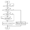
- FIG. 3 is a flowchart illustrating another example of the operation of the control unit 3 when the battery pack 1 is used (during vehicle travel). It is assumed that all relays R are on. Also, S31, S32, and S33 shown in FIG. 3 are the same processes as S21, S22, and S23 shown in FIG.
- each relay R is immediately selected. All R are turned off (S36). For example, the control unit 3 determines whether or not each relay R is closed and fixed at the start of charging of the battery pack 1 or at the end of charging of the battery pack 1, and the determination result is used as the processing of S34. Used when Further, when the control unit 3 sends an instruction to turn off the relay R to the monitoring unit 23 but the current indicated in the battery state information sent from the monitoring unit 23 is not zero, the relay R Is determined to be closed and stuck.
- control unit 3 determines that all the relays R should be turned off (S32: Yes), and determines that at least one relay R is closed and fixed (S34: Yes), a predetermined time. After the elapse (S35: Yes), all the relays R are turned off (S36).
- FIG. 4 is a flowchart showing still another example of the operation of the control unit 3 when the battery pack 1 is used (during vehicle travel). It is assumed that all relays R are on. Also, S41, S42, and S43 shown in FIG. 4 are the same processes as S21, S22, and S23 shown in FIG.
- the control unit 3 determines that all the relays R should be turned off (S42: Yes)
- the control unit 3 transmits a message to that effect to the travel control unit 4 (S44) and notifies the travel control unit 4 that the travel stop process has started.
- S45: Yes when the fact that the vehicle has stopped is received from the travel control unit 4 (S46: No), all the relays R are turned off (S47).
- the travel control unit 4 receives from the control unit 3 that it has determined that all the relays R should be turned off, the travel control unit 4 starts the travel stop process and informs the control unit 3 that the travel stop process has started. After that, when the vehicle is stopped by the travel stop process, the fact is transmitted to the control unit 3. Further, when the vehicle stops, the regenerative current does not flow from the load Lo to the battery pack 1.
- the relay R when it is determined that all the relays R should be turned off, the relay R is turned off after the vehicle stops after starting the travel stop process. Therefore, similarly to the battery pack 1 of the first embodiment, for example, after the regenerative current flowing from the load Lo to the battery pack 1 stops, all the relays R can be turned off. Thereby, when all the relays R are turned off, even if at least one relay R is closed and fixed, current is not concentrated on the battery module 2 having the closed and fixed relay R. Can do.
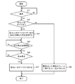
- FIG. 5 is a flowchart showing still another example of the operation of the control unit 3 when the battery pack 1 is in use (during vehicle travel). It is assumed that all relays R are on. Also, S51, S52, and S53 shown in FIG. 5 are the same processes as S21, S22, and S23 shown in FIG.
- the control unit 3 determines that all the relays R should be turned off (S52: Yes)
- the control unit 3 transmits a message to that effect to the travel control unit 4 (S54) and notifies the travel control unit 4 that the travel stop process has started.
- S55: Yes when it is determined that the current flowing through the entire battery pack 1 has become a predetermined value or less (S56: Yes), all the relays R are turned off (S57).
- the control unit 3 sets the total current flowing through each battery B as the current flowing through the battery pack 1 as a whole.
- the control unit 3 sets the multiplication result of the current flowing through one battery module 2 and the number of battery modules 2 provided in the battery pack 1 as the current flowing through the battery pack 1 as a whole.
- the said predetermined value shall be set based on the rated current of the battery B, the relay R, etc., for example.
- the battery pack 1 of the fourth embodiment when it is determined that all the relays R should be turned off, after the travel stop process is started, the current flowing through the battery pack 1 as a whole becomes a predetermined value or less. Since all the relays R are turned off, all the relays R can be turned off after the regenerative current flowing from the load Lo to the battery pack 1 becomes a predetermined value or less. Thereby, when all the relays R are turned off, even if at least one of the relays R is closed and fixed, it is possible to suppress the current that flows in a concentrated manner in the battery module 2 having the closed and fixed relay R. It is possible to suppress an overcurrent from flowing through the battery B of the battery module 2.
- the predetermined time is not limited to the time after the control unit 3 determines that all the relays R should be turned off and sends the fact to the travel control unit 4 on the vehicle side. It may be the time after it is determined that all should be turned off, or after the fact that the control unit 3 has decided to be sent to the vehicle-side travel control unit 4, the fact that the travel stop process has been started is received from the travel control unit 4. It may be a long time.
Abstract
L'invention concerne un bloc-batterie (1) comprenant: une pluralité de modules de batterie (2) comprenant chacun une batterie (B) et un relais (R) connectés en série, les modules de batterie (2) étant connectés en parallèle les uns aux autres ; et une unité de commande (3) permettant d'activer ou de désactiver chacun des relais (R). Lorsqu'il est déterminé que tous les relais (R) doivent être désactivés, l'unité de commande (3) désactive tous les relais (R) après l'écoulement d'une durée prédéterminé.
Applications Claiming Priority (2)
| Application Number | Priority Date | Filing Date | Title |
|---|---|---|---|
| JP2015-246073 | 2015-12-17 | ||
| JP2015246073A JP6555114B2 (ja) | 2015-12-17 | 2015-12-17 | 電池パック |
Publications (1)
| Publication Number | Publication Date |
|---|---|
| WO2017104393A1 true WO2017104393A1 (fr) | 2017-06-22 |
Family
ID=59056404
Family Applications (1)
| Application Number | Title | Priority Date | Filing Date |
|---|---|---|---|
| PCT/JP2016/085290 WO2017104393A1 (fr) | 2015-12-17 | 2016-11-29 | Bloc-batterie |
Country Status (2)
| Country | Link |
|---|---|
| JP (1) | JP6555114B2 (fr) |
| WO (1) | WO2017104393A1 (fr) |
Cited By (1)
| Publication number | Priority date | Publication date | Assignee | Title |
|---|---|---|---|---|
| JP2021097501A (ja) * | 2019-12-17 | 2021-06-24 | 京セラ株式会社 | 電力制御装置および電力制御方法 |
Families Citing this family (4)
| Publication number | Priority date | Publication date | Assignee | Title |
|---|---|---|---|---|
| KR102433848B1 (ko) * | 2018-09-12 | 2022-08-17 | 주식회사 엘지에너지솔루션 | 스위치 진단 장치 및 방법 |
| CN109849733B (zh) * | 2019-02-19 | 2021-02-19 | 广州小鹏汽车科技有限公司 | 用于电动车辆高压继电器粘连检测及处理的装置和方法 |
| CN110774937B (zh) * | 2019-10-30 | 2022-11-08 | 电子科技大学 | 一种车载集中配电式并联电池管理系统 |
| CN111251943B (zh) * | 2020-03-17 | 2021-07-27 | 上海度普新能源科技有限公司 | 一种电池组的均衡方法及装置 |
Citations (5)
| Publication number | Priority date | Publication date | Assignee | Title |
|---|---|---|---|---|
| JPH10271603A (ja) * | 1997-03-28 | 1998-10-09 | Mitsubishi Motors Corp | 電気自動車 |
| JP2000294297A (ja) * | 1999-04-02 | 2000-10-20 | Toyota Motor Corp | 電池充放電装置 |
| JP2006020380A (ja) * | 2004-06-30 | 2006-01-19 | Sanyo Electric Co Ltd | 車両用の電源装置 |
| JP2014050138A (ja) * | 2012-08-29 | 2014-03-17 | Toyota Industries Corp | バッテリシステム及びバッテリ |
| JP2014147168A (ja) * | 2013-01-28 | 2014-08-14 | Toyota Industries Corp | 退避走行時車速制限方法及び車両 |
-
2015
- 2015-12-17 JP JP2015246073A patent/JP6555114B2/ja active Active
-
2016
- 2016-11-29 WO PCT/JP2016/085290 patent/WO2017104393A1/fr active Application Filing
Patent Citations (5)
| Publication number | Priority date | Publication date | Assignee | Title |
|---|---|---|---|---|
| JPH10271603A (ja) * | 1997-03-28 | 1998-10-09 | Mitsubishi Motors Corp | 電気自動車 |
| JP2000294297A (ja) * | 1999-04-02 | 2000-10-20 | Toyota Motor Corp | 電池充放電装置 |
| JP2006020380A (ja) * | 2004-06-30 | 2006-01-19 | Sanyo Electric Co Ltd | 車両用の電源装置 |
| JP2014050138A (ja) * | 2012-08-29 | 2014-03-17 | Toyota Industries Corp | バッテリシステム及びバッテリ |
| JP2014147168A (ja) * | 2013-01-28 | 2014-08-14 | Toyota Industries Corp | 退避走行時車速制限方法及び車両 |
Cited By (2)
| Publication number | Priority date | Publication date | Assignee | Title |
|---|---|---|---|---|
| JP2021097501A (ja) * | 2019-12-17 | 2021-06-24 | 京セラ株式会社 | 電力制御装置および電力制御方法 |
| JP7325319B2 (ja) | 2019-12-17 | 2023-08-14 | 京セラ株式会社 | 電力制御装置および電力制御方法 |
Also Published As
| Publication number | Publication date |
|---|---|
| JP2017112759A (ja) | 2017-06-22 |
| JP6555114B2 (ja) | 2019-08-07 |
Similar Documents
| Publication | Publication Date | Title |
|---|---|---|
| WO2017104393A1 (fr) | Bloc-batterie | |
| US9211800B2 (en) | Battery system and control method of battery system | |
| US9041243B2 (en) | Power control apparatus | |
| JP2010088202A (ja) | 電池ユニットおよびこれを用いた電池システム | |
| US20140203735A1 (en) | Electric storage system and control method of electric storage system | |
| JP6708148B2 (ja) | 車載用電池の保護回路 | |
| JP6135823B2 (ja) | 電池監視装置 | |
| JP2005295697A (ja) | 車両用の電源装置 | |
| JP6087675B2 (ja) | 電池モジュール | |
| JP2014050138A (ja) | バッテリシステム及びバッテリ | |
| KR102351067B1 (ko) | 전기 자동차용 배터리 전원 공급 장치 및 방법 | |
| JP5864320B2 (ja) | バランス補正装置および蓄電システム | |
| JP2017114373A (ja) | ジャンクションボックス | |
| US10177560B2 (en) | Battery monitoring device | |
| JP2016086506A (ja) | 電池監視装置及び方法 | |
| WO2016060009A1 (fr) | Dispositif de commande de relais et procédé de commande de relais | |
| JP6265024B2 (ja) | 電池監視装置 | |
| JP6733581B2 (ja) | 電池パック | |
| JP6337793B2 (ja) | 蓄電装置 | |
| JP6323162B2 (ja) | 電池監視装置 | |
| JP6772931B2 (ja) | 電池パックの放電制御装置 | |
| JP2020072620A (ja) | 電源回路保護装置 | |
| JP5764680B2 (ja) | 突入電流防止装置 | |
| JP2016140163A (ja) | 給電路遮断装置及び給電路遮断方法 | |
| JP6409582B2 (ja) | 蓄電装置 |
Legal Events
| Date | Code | Title | Description |
|---|---|---|---|
| 121 | Ep: the epo has been informed by wipo that ep was designated in this application |
Ref document number: 16875377 Country of ref document: EP Kind code of ref document: A1 |
|
| NENP | Non-entry into the national phase |
Ref country code: DE |
|
| 122 | Ep: pct application non-entry in european phase |
Ref document number: 16875377 Country of ref document: EP Kind code of ref document: A1 |