WO2017104383A1 - 電池パック - Google Patents
電池パック Download PDFInfo
- Publication number
- WO2017104383A1 WO2017104383A1 PCT/JP2016/085026 JP2016085026W WO2017104383A1 WO 2017104383 A1 WO2017104383 A1 WO 2017104383A1 JP 2016085026 W JP2016085026 W JP 2016085026W WO 2017104383 A1 WO2017104383 A1 WO 2017104383A1
- Authority
- WO
- WIPO (PCT)
- Prior art keywords
- flow path
- battery pack
- path forming
- plate
- battery
- Prior art date
Links
Images


Classifications
-
- H—ELECTRICITY
- H01—ELECTRIC ELEMENTS
- H01M—PROCESSES OR MEANS, e.g. BATTERIES, FOR THE DIRECT CONVERSION OF CHEMICAL ENERGY INTO ELECTRICAL ENERGY
- H01M10/00—Secondary cells; Manufacture thereof
- H01M10/60—Heating or cooling; Temperature control
- H01M10/61—Types of temperature control
- H01M10/613—Cooling or keeping cold
-
- H—ELECTRICITY
- H01—ELECTRIC ELEMENTS
- H01M—PROCESSES OR MEANS, e.g. BATTERIES, FOR THE DIRECT CONVERSION OF CHEMICAL ENERGY INTO ELECTRICAL ENERGY
- H01M50/00—Constructional details or processes of manufacture of the non-active parts of electrochemical cells other than fuel cells, e.g. hybrid cells
- H01M50/20—Mountings; Secondary casings or frames; Racks, modules or packs; Suspension devices; Shock absorbers; Transport or carrying devices; Holders
- H01M50/249—Mountings; Secondary casings or frames; Racks, modules or packs; Suspension devices; Shock absorbers; Transport or carrying devices; Holders specially adapted for aircraft or vehicles, e.g. cars or trains
-
- B—PERFORMING OPERATIONS; TRANSPORTING
- B60—VEHICLES IN GENERAL
- B60L—PROPULSION OF ELECTRICALLY-PROPELLED VEHICLES; SUPPLYING ELECTRIC POWER FOR AUXILIARY EQUIPMENT OF ELECTRICALLY-PROPELLED VEHICLES; ELECTRODYNAMIC BRAKE SYSTEMS FOR VEHICLES IN GENERAL; MAGNETIC SUSPENSION OR LEVITATION FOR VEHICLES; MONITORING OPERATING VARIABLES OF ELECTRICALLY-PROPELLED VEHICLES; ELECTRIC SAFETY DEVICES FOR ELECTRICALLY-PROPELLED VEHICLES
- B60L50/00—Electric propulsion with power supplied within the vehicle
- B60L50/50—Electric propulsion with power supplied within the vehicle using propulsion power supplied by batteries or fuel cells
- B60L50/60—Electric propulsion with power supplied within the vehicle using propulsion power supplied by batteries or fuel cells using power supplied by batteries
- B60L50/64—Constructional details of batteries specially adapted for electric vehicles
-
- H—ELECTRICITY
- H01—ELECTRIC ELEMENTS
- H01M—PROCESSES OR MEANS, e.g. BATTERIES, FOR THE DIRECT CONVERSION OF CHEMICAL ENERGY INTO ELECTRICAL ENERGY
- H01M10/00—Secondary cells; Manufacture thereof
- H01M10/60—Heating or cooling; Temperature control
- H01M10/62—Heating or cooling; Temperature control specially adapted for specific applications
- H01M10/625—Vehicles
-
- H—ELECTRICITY
- H01—ELECTRIC ELEMENTS
- H01M—PROCESSES OR MEANS, e.g. BATTERIES, FOR THE DIRECT CONVERSION OF CHEMICAL ENERGY INTO ELECTRICAL ENERGY
- H01M10/00—Secondary cells; Manufacture thereof
- H01M10/60—Heating or cooling; Temperature control
- H01M10/65—Means for temperature control structurally associated with the cells
- H01M10/651—Means for temperature control structurally associated with the cells characterised by parameters specified by a numeric value or mathematical formula, e.g. ratios, sizes or concentrations
- H01M10/652—Means for temperature control structurally associated with the cells characterised by parameters specified by a numeric value or mathematical formula, e.g. ratios, sizes or concentrations characterised by gradients
-
- H—ELECTRICITY
- H01—ELECTRIC ELEMENTS
- H01M—PROCESSES OR MEANS, e.g. BATTERIES, FOR THE DIRECT CONVERSION OF CHEMICAL ENERGY INTO ELECTRICAL ENERGY
- H01M10/00—Secondary cells; Manufacture thereof
- H01M10/60—Heating or cooling; Temperature control
- H01M10/65—Means for temperature control structurally associated with the cells
- H01M10/655—Solid structures for heat exchange or heat conduction
- H01M10/6554—Rods or plates
-
- H—ELECTRICITY
- H01—ELECTRIC ELEMENTS
- H01M—PROCESSES OR MEANS, e.g. BATTERIES, FOR THE DIRECT CONVERSION OF CHEMICAL ENERGY INTO ELECTRICAL ENERGY
- H01M10/00—Secondary cells; Manufacture thereof
- H01M10/60—Heating or cooling; Temperature control
- H01M10/65—Means for temperature control structurally associated with the cells
- H01M10/655—Solid structures for heat exchange or heat conduction
- H01M10/6556—Solid parts with flow channel passages or pipes for heat exchange
-
- H—ELECTRICITY
- H01—ELECTRIC ELEMENTS
- H01M—PROCESSES OR MEANS, e.g. BATTERIES, FOR THE DIRECT CONVERSION OF CHEMICAL ENERGY INTO ELECTRICAL ENERGY
- H01M10/00—Secondary cells; Manufacture thereof
- H01M10/60—Heating or cooling; Temperature control
- H01M10/65—Means for temperature control structurally associated with the cells
- H01M10/656—Means for temperature control structurally associated with the cells characterised by the type of heat-exchange fluid
- H01M10/6561—Gases
- H01M10/6562—Gases with free flow by convection only
-
- H—ELECTRICITY
- H01—ELECTRIC ELEMENTS
- H01M—PROCESSES OR MEANS, e.g. BATTERIES, FOR THE DIRECT CONVERSION OF CHEMICAL ENERGY INTO ELECTRICAL ENERGY
- H01M10/00—Secondary cells; Manufacture thereof
- H01M10/60—Heating or cooling; Temperature control
- H01M10/65—Means for temperature control structurally associated with the cells
- H01M10/658—Means for temperature control structurally associated with the cells by thermal insulation or shielding
-
- H—ELECTRICITY
- H01—ELECTRIC ELEMENTS
- H01M—PROCESSES OR MEANS, e.g. BATTERIES, FOR THE DIRECT CONVERSION OF CHEMICAL ENERGY INTO ELECTRICAL ENERGY
- H01M50/00—Constructional details or processes of manufacture of the non-active parts of electrochemical cells other than fuel cells, e.g. hybrid cells
- H01M50/20—Mountings; Secondary casings or frames; Racks, modules or packs; Suspension devices; Shock absorbers; Transport or carrying devices; Holders
- H01M50/204—Racks, modules or packs for multiple batteries or multiple cells
- H01M50/207—Racks, modules or packs for multiple batteries or multiple cells characterised by their shape
- H01M50/209—Racks, modules or packs for multiple batteries or multiple cells characterised by their shape adapted for prismatic or rectangular cells
-
- H—ELECTRICITY
- H01—ELECTRIC ELEMENTS
- H01M—PROCESSES OR MEANS, e.g. BATTERIES, FOR THE DIRECT CONVERSION OF CHEMICAL ENERGY INTO ELECTRICAL ENERGY
- H01M50/00—Constructional details or processes of manufacture of the non-active parts of electrochemical cells other than fuel cells, e.g. hybrid cells
- H01M50/20—Mountings; Secondary casings or frames; Racks, modules or packs; Suspension devices; Shock absorbers; Transport or carrying devices; Holders
- H01M50/271—Lids or covers for the racks or secondary casings
-
- Y—GENERAL TAGGING OF NEW TECHNOLOGICAL DEVELOPMENTS; GENERAL TAGGING OF CROSS-SECTIONAL TECHNOLOGIES SPANNING OVER SEVERAL SECTIONS OF THE IPC; TECHNICAL SUBJECTS COVERED BY FORMER USPC CROSS-REFERENCE ART COLLECTIONS [XRACs] AND DIGESTS
- Y02—TECHNOLOGIES OR APPLICATIONS FOR MITIGATION OR ADAPTATION AGAINST CLIMATE CHANGE
- Y02E—REDUCTION OF GREENHOUSE GAS [GHG] EMISSIONS, RELATED TO ENERGY GENERATION, TRANSMISSION OR DISTRIBUTION
- Y02E60/00—Enabling technologies; Technologies with a potential or indirect contribution to GHG emissions mitigation
- Y02E60/10—Energy storage using batteries
Definitions
- One aspect of the present invention relates to a battery pack.
- Patent Document 1 describes a battery-type forklift.
- the forklift includes a pump driving motor that drives a hydraulic pump, a battery that supplies driving power to the electric motor, and a controller for traveling and work control.
- a pump driving motor that generates heat during operation and an electrical device such as a controller with low heat resistance are arranged apart from each other with a battery in between.
- the motor and the electric device are separated from each other with the battery interposed therebetween, thereby preventing the electric device from being heated by the heat generated by the motor or the like.
- the cooling effect is improved.
- the battery may be heated because the motor or the like adjacent to the battery generates heat.
- improvement of the cooling effect of the battery itself has not been studied. From these viewpoints, according to the forklift described in Patent Document 1, there is a risk that the reliability of the battery may be lowered, for example, the durability of the battery may be reduced due to the temperature rise of the battery.
- an object of one aspect of the present invention is to provide a battery pack capable of improving reliability.
- a battery pack is a battery pack that is mounted on a vehicle including a heat generating portion, and includes a battery module including a plurality of battery cells, a first outer surface, and houses the battery module.
- the member is a first coolant channel that extends in a vertical direction between a first fixing portion for fixing the first plate-like member to the housing and a first outer surface connected to the first fixing portion.
- the housing that houses the battery module includes a first outer surface that faces the heat generating portion of the vehicle.
- a first plate-like member is fixed to the housing so as to face the first outer surface.
- the first flow path forming portion forms a first refrigerant flow path extending in the up-down direction between the first outer surface of the housing. For this reason, the heat from the heat generating part of the vehicle is blocked by the first flow path forming portion of the first plate-like member and the first refrigerant flow path, and is difficult to reach the battery pack. Therefore, it is suppressed that a battery cell is heated with the heat from the heat-emitting part of a vehicle.
- a refrigerant for example, air
- a chimney effect in the first refrigerant flow path, heat dissipation from the battery cells is promoted in addition to the interruption of heat from the heat generating portion. Therefore, according to this battery pack, it is possible to suppress a decrease in durability due to a temperature rise of the battery cell and to improve reliability.
- the first fixing portion is disposed on the first outer surface, and the first flow path forming portion is separated from the first outer surface.
- the first plate-like member is fixed to the housing by fastening the first fixing portion to the first outer surface by a fastening member, and the first flow from the first fixing portion is
- the protruding amount of the path forming portion may be larger than the protruding amount of the fastening member from the first fixed portion. In this case, it is avoided that the fastening member protrudes most in the entire outer shape of the battery pack. For this reason, for example, when the battery pack is mounted on the vehicle or when the battery pack is removed from the vehicle, the fastening member is prevented from coming into contact with the vehicle-side components. As a result, the fixing of the first plate member to the housing is stabilized, and the reliability is further improved.
- the first flow path forming portion may have a corrugated shape by arranging concave and convex portions extending in the vertical direction along the first outer surface. Good. In this case, heat dissipation through the first refrigerant channel is improved by increasing the surface area of the first channel forming portion. In addition, the strength of the first flow path forming portion is improved.
- the housing includes a bottom surface that is connected to the lower end of the first outer surface and extends in a direction intersecting the first outer surface, and the bottom surface intersects the first outer surface.
- a groove portion may be formed that extends to reach the first outer surface along the direction.
- the lower end of the first flow path forming portion may be located between the flat portion defining the groove portion on the bottom surface and the bottom portion of the groove portion. In this case, the refrigerant that flows toward the first outer surface along the bottom of the groove can be reliably introduced into the first refrigerant flow path.
- the lower end portion including the lower end of the first flow path forming portion may be inclined so as to approach the first outer surface toward the bottom surface. In this case, the refrigerant that flows toward the first outer surface along the bottom of the groove can be more reliably introduced into the first refrigerant flow path.
- the battery pack according to one aspect of the present invention includes a second plate-like member fixed to the housing on the second outer surface opposite to the first outer surface of the housing, and the second plate-like member is Forming a second refrigerant channel extending in the vertical direction between the second fixing portion for fixing the second plate-shaped member to the housing and the second outer surface connected to the second fixing portion.
- the bottom surface is connected to the lower end of the second outer surface, and the groove portion may extend to reach the second outer surface.
- heat dissipation of the battery cell can be promoted via the second refrigerant flow path.
- the refrigerant flowing through the groove toward the second outer surface can be introduced into the second refrigerant flow path.
- the refrigerant flowing through the groove portion as the vehicle advances or retreats is set to either the first refrigerant flow path or the second refrigerant flow path. It becomes possible to introduce.
- a battery pack capable of improving reliability can be provided.
- FIG. It is a side view which shows a reach lift. It is a schematic diagram which shows the vehicle body shown by FIG. It is a figure which shows the battery module shown by FIG. It is a figure which shows the battery pack shown by FIG. It is a figure which shows the modification of the battery pack shown by FIG. It is a schematic diagram which shows the vehicle body shown by FIG. It is a figure which shows the battery pack shown by FIG. It is a figure which shows the battery pack shown by FIG. It is sectional drawing which shows a mode that a refrigerant
- the battery pack according to this embodiment is mounted on a vehicle.
- the vehicle is, for example, an industrial vehicle.
- An example of the industrial vehicle is a forklift that performs a cargo handling operation.
- a reach lift will be described as an example of a forklift.
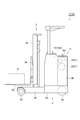
- FIG. 1 is a side view showing a reach lift.
- FIG. 2 is a schematic diagram showing the vehicle body shown in FIG. 2A is a schematic cross-sectional view in plan view
- FIG. 2B is a schematic cross-sectional view in side view.
- the reach lift 1 includes a vehicle body 2, a cargo handling device 3, and a cab 4.
- the reach lift 1 is a compact forklift that a driver stands and operates.
- the body 2 of the reach lift 1 is smaller than the body of the counter-type forklift.
- the size of the vehicle body 2 in the front-rear direction is relatively small.
- “front”, “rear”, “left”, and “right” indicate directions when the direction from the cab 4 toward the cargo handling device 3 is the “front” direction.
- “upper” and “lower” in the following description indicate a vertically upward direction and a vertically downward direction, respectively.
- the vehicle body 2 includes a pedestal portion 2a and a main body portion 2b.
- the pedestal portion 2 a is disposed at the lower part of the vehicle body 2.
- the pedestal portion 2a has a rectangular parallelepiped shape, for example.
- a rear wheel (drive wheel and steering wheel) 2c and a caster wheel (not shown) are provided in the lower rear portion of the pedestal portion 2a.
- the right rear part on the upper surface of the base part 2a is a floor E on which the driver stands.
- the main body 2b is disposed on the top of the pedestal 2a.
- the main body 2b is substantially L-shaped in plan view.
- the interior of the main body 2b is a storage space S for various devices.
- the front portion of the accommodation space S is a space that extends over substantially the entire region of the reach lift 1 in the left-right direction (vehicle width direction).
- the rear portion of the accommodation space S is a space that extends over a substantially left half region of the reach lift 1 in the left-right direction.
- a traveling motor 2d and a cargo handling motor 2e are disposed on the upper side of the rear portion of the accommodation space S.
- the traveling motor 2d is a motor that is a drive source of the drive wheels.
- the cargo handling motor 2 e is a motor that is a drive source of the cargo handling device 3.
- the battery pack 10 is disposed in the front part of the accommodation space S.
- the battery pack 10 serves as a power source for the traveling motor 2d and the cargo handling motor 2e.
- the traveling motor 2d, the cargo handling motor 2e, the inverter for driving them, and the like generate heat during operation and may be hotter than the battery pack 10. That is, the traveling motor 2d, the cargo handling motor 2e, the inverter, and the like constitute a heat generating portion T in the reach lift (vehicle) 1.
- the cargo handling device 3 has a pair of left and right reach legs 3a, a fork 3b, and a mast 3c.
- the reach leg 3a is provided forward from the front end of the pedestal 2a.
- a front wheel 3d is provided at the lower front part of each reach leg 3a.
- the mast 3c is erected in front of the main body 2b.
- the mast 3c is attached to a pair of left and right reach legs 3a so as to be movable in the front-rear direction.
- the mast 3c is movable in the front-rear direction along a pair of left and right reach legs 3a by a driving force of a reach cylinder (not shown).
- the fork 3b is attached to the mast 3c via a lift bracket 3e.
- the fork 3b is a member for supporting the load A.
- the fork 3b is movable in the vertical direction along the mast 3c by a driving force of a lift cylinder (not shown) coupled to the mast 3c.
- a lift cylinder (not shown) coupled to the mast 3c.
- a vacant space on the right side of the rear part of the vehicle body 2 is the floor E.
- a handle 4 a is provided on the left side of the floor E.
- FIG. 3 is a diagram illustrating the battery module illustrated in FIG. 2.
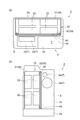
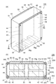
- FIG. 4 is a diagram showing the battery pack shown in FIGS. 4A is a perspective view, and FIG. 4B is a cross-sectional view along IVb-IVb in FIG. 4A.
- the battery pack 10 according to the present embodiment is mounted on a reach lift 1 including a heat generating portion T.
- the battery pack 10 includes a plurality of battery modules 20, a housing 30 that houses the battery modules 20, and a heat shield plate (first plate-like member) 40.
- the battery module 20 is arranged in seven out of a total of eight places, which are arranged in two rows in the vertical direction in the housing 30, two rows in the front-rear direction, and two rows in the left-right direction.
- another member other than the battery module 20 can be disposed in the remaining one place.
- the number of the battery modules 20 it can set suitably according to a specification.
- the arrangement location of the battery module 20 can be appropriately set according to the shape of the housing 30 and the like.
- a smaller number of battery modules 20 than the number that can be accommodated in the housing 30 may be accommodated.
- a dummy module for adjusting the weight of the counterweight may be provided in a vacant part in the housing 30.
- the battery module 20 includes a plurality (seven in this case) of battery cells 21 stacked on each other. Each battery cell 21 is held by a holder 22. The battery cells 21 are arranged in one direction while being held by the holder 22.
- the battery cell 21 is, for example, a storage battery such as a non-aqueous electrolyte secondary battery such as a lithium ion secondary battery, or an electric double layer capacitor.
- the battery cell 21 is configured, for example, by accommodating an electrolytic solution and an electrode assembly (not shown) in a case.
- the electrode assembly has a plurality of separators that insulate the positive electrode, the negative electrode, and the positive electrode and the negative electrode.
- the plurality of positive electrodes, negative electrodes, and separators are stacked with the separators sandwiched between the positive electrodes and the negative electrodes.
- the battery cell 21 has a positive electrode terminal 21a and a negative electrode terminal 21b.
- the plurality of battery cells 21 are arranged so that the positive electrode terminal 21a and the negative electrode terminal 21b are adjacent to each other. Between the battery cells 21, the positive terminal 21 a and the negative terminal 21 b are electrically connected by the bus bar 23. Thereby, the battery cells 21 are connected in series with each other.
- a heat transfer plate 24 is provided between the battery cells 21 adjacent to each other.
- the heat transfer plate 24 has a substantially L-shaped flat plate shape.
- One flat plate portion of the heat transfer plate 24 is disposed between the battery cells 21 and the battery cell 21, and the other flat plate portion is disposed in contact with the housing 30. Thereby, the heat transfer plate 24 thermally connects the battery cell 21 and the housing 30.
- the material of the heat transfer plate 24 is, for example, a metal such as iron.
- End plates 25 are provided at both ends in the stacking direction of the battery cells 21.
- the plurality of battery cells 21 are restrained using restraining bolts 26 while being sandwiched between a pair of end plates 25, and a restraining load is applied thereto.
- a bracket 27 is attached to the outer surface 25 a of the end plate 25.
- the bracket 27 is formed in a substantially L-shaped flat plate shape using, for example, a metal such as iron.
- the bracket 27 includes a first flat plate portion 27a and a second flat plate portion 27b formed so as to be orthogonal to the first flat plate portion 27a at one edge portion of the first flat plate portion 27a. .
- the first flat plate portion 27 a is fixed to the end plate 25 using bolts 28.
- the second flat plate portion 27 b is fixed to the housing 30 using bolts 29.
- the battery module 20 is fixed to the housing 30 using a pair of brackets 27.
- the housing 30 includes a rectangular box-shaped storage portion 31 that is open on one side, and a rectangular plate-shaped lid portion 32 that is fixed to the storage portion 31 so as to close an open portion of the storage portion 31.
- the battery module 20 is accommodated in the accommodating portion 31 in a state where the lid portion 32 is fixed to the accommodating portion 31.
- the battery module 20 on the bottom wall 31a side of the accommodating portion 31 among the plurality of battery modules 20 is fixed to the bottom wall 31a.
- the battery module 20 on the bottom wall 31 a side is thermally connected to the bottom wall 31 a via the heat transfer plate 24.
- the battery module 20 on the lid portion 32 side among the plurality of battery modules 20 is fixed to the lid portion 32.
- the battery module 20 on the lid portion 32 side is thermally connected to the lid portion 32 via the heat transfer plate 24.
- the housing 30 includes a first outer surface 33 and a second outer surface 34 opposite to the first outer surface 33.
- the first outer surface 33 is an outer surface on the opposite side of the housing portion 31 in the lid portion 32.
- the second outer surface 34 is an outer surface of the bottom wall 31a opposite to the lid portion 32.
- the first outer surface 33 is a surface facing the heat generating portion T when the battery pack 10 is mounted on the reach lift 1.
- the first outer surface 33 and the second outer surface 34 are parallel to each other and intersect the advance direction and the reverse direction of the reach lift 1.
- the housing 30 includes a bottom surface 35 connected to the lower end of the first outer surface 33 and the lower end of the second outer surface 34.
- the bottom surface 35 is a surface along the forward direction and the backward direction of the reach lift 1.
- the heat shield plate 40 is fixed to the housing 30 so as to face the first outer surface 33 of the housing 30.
- the heat shield plate 40 is made of, for example, a metal such as aluminum, iron, and copper, or a resin.
- the heat shield plate 40 is provided so as to cover the entire first outer surface 33 when viewed from the direction intersecting the first outer surface 33.
- the heat shield plate 40 includes a pair of plate-like fixing portions (first fixing portions) 41, a plate-like flow passage forming portion (first flow passage forming portion) 42, and a pair of plate-like connecting portions 43. And including.
- the fixing part 41, the flow path forming part 42, and the connection part 43 are integrally formed with each other.
- the fixing part 41 is used for fixing the heat shield plate 40 to the housing 30. More specifically, the fixing portion 41 is disposed at both left and right end portions of the first outer surface 33 and has a rectangular plate shape extending in the vertical direction along the first outer surface 33.
- the heat shield plate 40 is fixed to the housing 30 by fastening the fixing portion 41 to the first outer surface 33 with a bolt (fastening member) 44 in a state where the fixing portion 41 is in contact with the first outer surface 33. Yes.
- the bolt 44 penetrates the fixing portion 41, the lid portion 32, and the accommodating portion 31, and fastens them together. A head 44 h of the bolt 44 protrudes from the fixing portion 41.
- the flow path forming part 42 is connected to the fixing part 41 via the connection part 43. More specifically, the flow path forming portion 42 extends from one fixing portion 41 to the other fixing portion 41 and is connected to each fixing portion 41 via a connection portion 43.
- the flow path forming portion 42 has a flat plate shape extending so as to cover the entire portion where the battery module 20 is disposed in the lid portion 32 when viewed from the direction intersecting the first outer surface 33. .
- the flow path forming portion 42 is substantially parallel to the first outer surface 33.
- the flow path forming portion 42 protrudes from the fixed portion 41 so as to be separated from the first outer surface 33.
- the protrusion amount A42 of the flow path forming portion 42 from the fixed portion 41 is larger than the protrusion amount A44 of the head portion 44h of the bolt 44 from the fixed portion 41. Therefore, the flow path forming portion 42 protrudes from the head 44 h of the bolt 44 as the entire outer shape of the battery pack 10.
- the flow path forming portion 42 faces the first outer surface 33 while being separated from the first outer surface 33.
- the flow path forming unit 42 forms a refrigerant flow path (first refrigerant flow path) 45 extending in the vertical direction between the first outer surface 33 and the first outer surface 33.
- the refrigerant channel 45 is opened in the vertical direction. Therefore, for example, a refrigerant (for example, air) can be introduced from the lower end of the refrigerant flow path 45 and the refrigerant can be discharged from the upper end of the refrigerant flow path 45. That is, a refrigerant layer (for example, an air layer) that can move at least in the vertical direction is formed between the first outer surface 33 and the heat generating portion T.
- a refrigerant layer for example, an air layer
- the housing 30 that houses the battery module 20 includes the first outer surface 33 that faces the heat generating portion T when the battery pack 10 is mounted on the reach lift 1.
- a heat shield plate 40 is fixed to the housing 30 so as to face the first outer surface 33.
- the flow path forming portion 42 is provided between the first outer surface 33 of the housing 30 and the refrigerant flow path 45 extending in the vertical direction with the battery pack 10 mounted on the reach lift 1. Forming. For this reason, the heat from the heat generating portion T of the reach lift 1 is blocked by the flow path forming portion 42 of the heat shield plate 40 and the refrigerant flow path 45 and is unlikely to reach the battery pack 10.
- the battery cell 21 is suppressed from being heated by the heat from the heat generating portion T of the reach lift 1.
- a refrigerant for example, air
- the refrigerant flow path 45 in addition to the heat blocking from the heat generating portion T, the heat radiation of the battery cell 21 is promoted. Therefore, according to the battery pack 10, it is possible to suppress a decrease in durability due to a temperature rise of the battery cell 21 and improve reliability.
- the fixing portion 41 of the heat shield plate 40 is disposed on the first outer surface 33, and the flow path forming portion 42 protrudes from the fixing portion 41 so as to be separated from the first outer surface 33. Yes.
- the heat shield plate 40 is fixed to the housing 30 by fastening the fixing portion 41 to the first outer surface 33 with bolts 44.
- the protrusion amount A42 of the flow path forming portion 42 from the fixing portion 41 is larger than the protrusion amount A44 of the head portion 44h of the bolt 44 from the fixing portion 41.
- the head 44h of the bolt 44 from protruding most in the entire outer shape of the battery pack 10.
- the head 44h of the bolt 44 contacts the components on the reach lift 1 side. It is suppressed. Therefore, the fixing of the heat shield plate 40 to the housing 30 is stabilized, and the reliability is further improved.
- the heat shield plate 40 may not cover the entire first outer surface 33 when viewed from the direction intersecting the first outer surface 33.
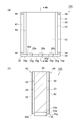
- a heat shield plate may be selectively provided on a part of the first outer surface 33 when viewed from the direction intersecting the first outer surface 33. An example of this case will be described.
- the battery pack 10 can include a heat shield plate 40A shown in FIG. 5A instead of the heat shield plate 40.
- the heat shield plate 40 ⁇ / b> A is provided only in the facing region F that faces the heat generation site T in the first outer surface 33.
- the facing region F extends from one end (left end) of the first outer surface 33 to the center of the first outer surface 33.
- One end (left end) of the facing region F coincides with one end of the first outer surface 33.
- the other end portion (right end portion) of the facing region F is located at the center portion of the first outer surface 33 so as to be positioned between the battery modules 20 adjacent to each other when viewed from the direction intersecting the first outer surface 33. is doing.
- the heat shield plate 40 ⁇ / b> A includes a pair of fixing portions 41, a flow path forming portion (first flow path forming portion) 42 ⁇ / b> A, and a pair of connection portions 43.
- the fixed portion 41 is disposed at both ends of the facing region F. That is, one fixing portion 41 is disposed at one end portion of the first outer surface 33.
- the other fixing portion 41 is disposed at the center of the first outer surface 33 so as to be positioned between the battery modules 20 adjacent to each other when viewed from the direction intersecting the first outer surface 33.
- the heat shield plate 40A is fixed to the casing 30 by fastening one fixing portion 41 to the first outer surface 33 with a bolt 44 and welding the other fixing portion 41 to the lid portion 32. Yes.
- the fixing of the heat shield plate to the housing 30 is not limited to the fastening by the fastening member, and any fixing method such as welding or adhesion can be used.
- the flow path forming part 42 ⁇ / b> A is connected to the fixed part 41 via the connection part 43. More specifically, the flow path forming part 42 ⁇ / b> A extends from one fixing part 41 to the other fixing part 41, and is connected to each fixing part 41 via a connection part 43. Therefore, here, the flow path forming portion 42 ⁇ / b> A has a flat plate shape extending so as to cover only the facing region F when viewed from the direction intersecting the first outer surface 33. Further, the flow path forming portion 42 ⁇ / b> A is substantially parallel to the first outer surface 33. The flow path forming portion 42 ⁇ / b> A faces the first outer surface 33 while being separated from the first outer surface 33. Thereby, the flow path forming part 42 ⁇ / b> A forms the refrigerant flow path 45 between the first outer surface 33 and the facing area F.
- the refrigerant flow path 45 is formed only in the facing region F facing the heat generation site T in the first outer surface 33, the heat from the heat generation site T can be blocked with the minimum necessary configuration. it can.
- the position which provides 40 A of heat shields can be selected arbitrarily. For example, in the vertical direction, when the facing region F occurs only in a part of the first outer surface 33 and / or when the facing region F occurs only in a part of the inner part of the first outer surface 33, The refrigerant flow path 45 may be formed by providing the heat shield plate 40A and the flow path forming portion 42A only in part.
- the facing region F is formed on a part of the first outer surface 33 so as to correspond to the lower battery module 20 among the battery modules 20 arranged in the vertical direction.
- it is effective to form the refrigerant flow path 45 only in a part thereof. This is because the refrigerant heated by the heat of the heat generating part T rises in the refrigerant flow path 45 toward the upper battery module 20 not facing the heat generating part T, thereby warming the battery module 20. It is for suppressing.
- the battery pack 10 can include a heat shield plate 40 ⁇ / b> B instead of the heat shield plate 40.
- the heat shield plate 40B is fixed to the housing 30 so as to face the first outer surface 33.
- the heat shield plate 40 ⁇ / b> B is provided so as to cover the entire first outer surface 33 when viewed from the direction intersecting the first outer surface 33.
- the heat shield plate 40 ⁇ / b> B includes a pair of fixing parts 41, a flow path forming part (first flow path forming part) 42 ⁇ / b> B, and a pair of connection parts 43.
- the heat shield plate 40 ⁇ / b> B is fixed to the housing 30 by fastening the fixing portion 41 to the first outer surface 33 with a bolt 44.
- the flow path forming part 42 ⁇ / b> B is connected to the fixing part 41 via the connection part 43. More specifically, the flow path forming part 42 ⁇ / b> B extends from one fixing part 41 to the other fixing part 41, and is connected to each fixing part 41 via a connection part 43.
- the flow path forming part 42 ⁇ / b> B faces the first outer surface 33 while being separated from the first outer surface 33. Thereby, the flow path forming part 42 ⁇ / b> B forms the refrigerant flow path 45 between the first outer surface 33.
- the flow path forming part 42 ⁇ / b> B has a corrugated plate shape in which a plurality of concave parts 42 a and convex parts 42 b extending in the vertical direction are arranged in the horizontal direction along the first outer surface 33.
- the flow path forming part 42B has a constant thickness also in the concave part 42a and the convex part 42b. Therefore, the flow path forming portion 42B is relatively far away from the first outer surface 33 in the convex portion 42b as compared with the concave portion 42a. Therefore, the coolant channel 45 is relatively wide at the convex portion 42b and relatively narrow at the concave portion 42a.
- the flow path forming portion 42B is also separated from the first outer surface 33 in the concave portion 42a. Therefore, the coolant channel 45 is also formed in the recess 42a.
- the flow path forming part 42B forming the refrigerant flow path 45 is formed into a corrugated plate shape by the concave part 42a and the convex part 42b, the surface area of the flow path forming part 42B is increased and the refrigerant flow path 45 is interposed. Improved heat dissipation. Further, the strength of the flow path forming part 42B is improved. Note that the heat shield plate 40B and the flow path forming portion 42B may be selectively provided only on a part of the first outer surface 33, similarly to the heat shield plate 40A and the flow path forming portion 42A. [Second Embodiment]
- FIG. 6 is a schematic diagram showing the vehicle body shown in FIG. 6A is a schematic cross-sectional view in plan view
- FIG. 6B is a schematic cross-sectional view in side view
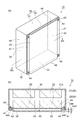
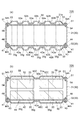
- 7 and 8 are diagrams showing the battery pack shown in FIGS. 7A is a perspective view
- FIG. 7B is a cross-sectional view taken along VIIb-VIIb in FIG. 7A
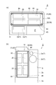
- 8A is a front view
- FIG. 8B is a cross-sectional view taken along line VIIIb-VIIIb in FIG. 8A.
- the battery pack 10A according to the present embodiment is mounted on a reach lift 1A including a heat generating portion T.
- the reach lift 1 ⁇ / b> A is the same as the reach lift 1 except that the battery pack 10 ⁇ / b> A is provided instead of the battery pack 10.
- the battery pack 10A is different from the battery pack 10 in that a plurality of grooves 35g are provided on the bottom surface 35 of the housing 30 and a heat shield plate (second plate-like member) 50 is further provided.
- the groove portions 35g extend along directions intersecting the first outer surface 33 and the second outer surface 34, respectively.
- the groove portion 35 g reaches both the first outer surface 33 and the second outer surface 34. Therefore, the groove portion 35 g is open on both the first outer surface 33 and the second outer surface 34.
- the groove part 35g has a rectangular parallelepiped shape. Accordingly, the bottom 35b of the groove 35g is flat.
- a portion between adjacent groove portions 35g is also a flat portion 35p.
- the heat shield plate 40 is provided so that the lower end 42 e of the flow path forming portion 42 does not reach the bottom surface 35 when viewed from the direction intersecting the first outer surface 33.
- the lower end 42e of the flow path forming portion 42 is located between the flat portion 35p that defines the groove portion 35g on the bottom surface 35 and the bottom portion 35b of the groove portion 35g. Therefore, as viewed from the direction intersecting the first outer surface 33, a part of the groove 35g on the bottom 35b side is covered with the flow path forming part 42, and the remaining part of the groove 35g is exposed from the flow path forming part 42. .
- the heat shield plate 50 has the same configuration as the heat shield plate 40 except for the difference in the position where it is provided. That is, the heat shield plate 50 is fixed to the housing 30 so as to face the second outer surface 34 of the housing 30.
- the heat shield plate 50 is made of, for example, a metal such as aluminum, iron, and copper, or a resin.
- the heat shield plate 50 is provided so as to cover substantially the entire second outer surface 34 when viewed from the direction intersecting the second outer surface 34.
- the heat shield plate 50 includes a pair of plate-like fixing portions (second fixing portions) 51, a plate-like flow passage forming portion (second flow passage forming portion) 52, and a pair of plate-like connecting portions 53. And including.
- the fixed part 51, the flow path forming part 52, and the connecting part 53 are integrally formed with each other.
- the fixing part 51 is used for fixing the heat shield plate 50 to the housing 30. More specifically, the fixing portion 51 is disposed at both left and right ends of the second outer surface 34 and has a rectangular plate shape extending in the vertical direction along the second outer surface 34.
- the heat shield plate 50 is fixed to the housing 30 by fastening the fixing portion 51 to the second outer surface 34 with a bolt (fastening member) 54 in a state where the fixing portion 51 is in contact with the second outer surface 34. Yes.
- the bolt 54 penetrates the fixing portion 51 and the accommodating portion 31 and fastens them together. A head 54 h of the bolt 54 protrudes from the fixing portion 51.
- the flow path forming part 52 is connected to the fixing part 51 via the connection part 53. More specifically, the flow path forming part 52 extends from one fixing part 51 to the other fixing part 51 and is connected to each fixing part 51 via a connection part 53.
- the flow path forming part 52 has a flat plate shape extending so as to cover substantially the entire part of the housing part 31 where the battery module 20 is disposed, as viewed from the direction intersecting the second outer surface 34. is there.
- the flow path forming part 52 is substantially parallel to the second outer surface 34.
- the flow path forming portion 52 protrudes from the fixed portion 51 so as to be separated from the second outer surface 34.
- the protrusion amount A52 of the flow path forming portion 52 from the fixed portion 51 is larger than the protrusion amount A54 of the head 54h of the bolt 54 from the fixed portion 51.
- the flow path forming part 52 faces the second outer surface 34 while being separated from the second outer surface 34. Thereby, the flow path forming part 52 forms a refrigerant flow path (second refrigerant flow path) 55 extending in the vertical direction between the second outer surface 34.
- the refrigerant channel 55 is open in the up-down direction.
- the refrigerant for example, air
- the refrigerant can be introduced from the lower end of the refrigerant flow path 55 and the refrigerant can be discharged from the upper end of the refrigerant flow path 55.
- a refrigerant layer for example, an air layer that can move at least in the vertical direction is formed on the second outer surface 34.
- the heat shield plate 50 is provided so that the lower end 52 e of the flow path forming portion 52 does not reach the bottom surface 35 when viewed from the direction intersecting the second outer surface 34.
- the lower end 52e of the flow path forming portion 52 is located between the flat portion 35p that defines the groove portion 35g on the bottom surface 35 and the bottom portion 35b of the groove portion 35g. Therefore, when viewed from the direction intersecting the second outer surface 34, a part of the groove 35 g on the bottom 35 b side is covered with the flow path forming part 52, and the remaining part of the groove 35 g is exposed from the flow path forming part 52. .
- the battery pack 10A as described above can exhibit the following new effects. That is, in the battery pack 10 ⁇ / b> A, the bottom surface 35 of the housing 30 is formed with a groove portion 35 g that extends to reach the first outer surface 33 along the direction intersecting the first outer surface 33. For this reason, as shown in FIG. 9A, for example, when the reach lift 1A moves forward, the refrigerant C flowing through the groove 35g toward the first outer surface 33 can be introduced into the refrigerant flow path 45. it can. For this reason, the heat dissipation through the refrigerant flow path 45 is improved.
- the lower end 42e of the flow path forming portion 42 is located between the flat portion 35p on the bottom surface 35 and the bottom portion 35b of the groove portion 35g. For this reason, it becomes possible to reliably introduce the refrigerant C flowing toward the first outer surface 33 along the bottom 35b of the groove 35g into the refrigerant flow path 45.
- the refrigerant C is air around the battery pack 10A, for example, and flows through the groove 35g by moving relative to the battery pack 10A as the reach lift 1A moves forward or backward.
- the battery pack 10 ⁇ / b> A includes a heat shield plate 50 on the second outer surface 34 opposite to the first outer surface 33.
- the heat shield plate 50 includes a flow path forming portion 52 that forms a coolant flow path 55 extending in the vertical direction between the heat shield plate 50 and the second outer surface 34. Therefore, according to the battery pack 10 ⁇ / b> A, the heat radiation of the battery cell 21 can be promoted through the refrigerant flow path 55.
- the groove portion 35 g of the bottom surface 35 extends so as to reach the second outer surface 34. For this reason, as shown in FIG. 9B, for example, when the reach lift 1A is retracted, the refrigerant C flowing through the groove 35g toward the second outer surface 34 can be introduced into the refrigerant flow path 55. it can. Therefore, heat dissipation through the refrigerant flow path 55 is improved.
- the lower end 52e of the flow path forming portion 52 is located between the flat portion 35p on the bottom surface 35 and the bottom portion 35b of the groove portion 35g. For this reason, it becomes possible to reliably introduce the refrigerant C flowing toward the second outer surface 34 along the bottom 35b of the groove 35g into the refrigerant flow channel 55.
- the battery pack 10A for example, if the extending direction of the groove 35g is set along the advance / retreat direction of the reach lift 1A, the refrigerant C flowing through the groove 35g as the reach lift 1A advances and retreats is allowed to flow through the refrigerant flow. It becomes possible to introduce into either the channel 45 or the refrigerant channel 55.
- the battery pack 10A can be deformed as shown in FIG. That is, in the battery pack 10 ⁇ / b> A, the lower end portion 42 p including the lower end 42 e of the flow path forming portion 42 may be inclined so as to approach the first outer surface 33 toward the bottom surface 35. Further, the lower end 52 p including the lower end 52 e of the flow path forming unit 52 may be inclined so as to approach the second outer surface 34 toward the bottom surface 35. The lower end 42 e is separated from the first outer surface 33, and the lower end 52 e is separated from the second outer surface 34.
- the battery pack 10A includes the heat shield plate 40B instead of the heat shield plate 40, and includes the heat shield plate 50B instead of the heat shield plate 50.
- the heat shield plate 50B has the same configuration as the heat shield plate 40B except for the difference in the position where it is provided. That is, the heat shield plate 50 ⁇ / b> B includes a pair of fixing parts 51, a flow path forming part (first flow path forming part) 52 ⁇ / b> B, and a pair of connection parts 53.
- the flow path forming part 52 ⁇ / b> B is connected to the fixed part 51 via the connection part 53. More specifically, the flow path forming part 52 ⁇ / b> B extends from one fixing part 51 to the other fixing part 51, and is connected to each fixing part 51 via a connection part 53.
- the flow path forming part 52 ⁇ / b> B faces the second outer surface 34 while being separated from the second outer surface 34. Thereby, the flow path forming part 52 ⁇ / b> B forms the refrigerant flow path 55 between the second outer surface 34.
- the flow path forming portion 52B has a corrugated plate shape in which a plurality of concave portions 52a and convex portions 52b extending in the vertical direction are arranged in the horizontal direction along the second outer surface 34.
- the flow path forming portion 52B has a constant thickness also in the concave portion 52a and the convex portion 52b. Therefore, the flow path forming part 52B is relatively far away from the second outer surface 34 in the convex part 52b as compared with the concave part 52a. Therefore, the coolant channel 55 is relatively wide at the convex portion 52b and relatively narrow at the concave portion 52a.
- the flow path forming portion 52B is also separated from the second outer surface 34 in the recess 52a. Therefore, the coolant channel 55 is also formed in the recess 52a.
- the recess 42a of the flow path forming part 42B and the recess 52a of the flow path forming part 52B are provided at positions facing each other as viewed in the direction intersecting the first outer surface 33 and the second outer surface 34.
- the convex portion 42b of the flow path forming portion 42B and the convex portion 52b of the flow path forming portion 52B are opposed to each other when viewed from the direction intersecting the first outer surface 33 and the second outer surface 34. Is provided.
- the groove part 35g of the bottom face 35 is provided in the position corresponding to the convex parts 42b and 52b which mutually oppose, respectively. That is, the groove portion 35g extends from the convex portion 42b to the convex portion 52b facing the convex portion 42b.
- the flow path forming part 42B forming the refrigerant flow path 45 is formed into a corrugated plate shape by the concave part 42a and the convex part 42b, the surface area of the flow path forming part 42B is increased and the refrigerant flow path 45 is interposed. Improved heat dissipation. Further, if the flow path forming part 52B that forms the refrigerant flow path 55 is formed in a corrugated plate shape by the concave part 52a and the convex part 52b, the heat dissipation via the refrigerant flow path 55 is caused by the increase in the surface area of the flow path forming part 52B. Improves.
- the groove portion 35g of the bottom surface 35 is provided so as to correspond to the convex portions 42b and 52b. For this reason, it is possible to sufficiently introduce the refrigerant into a relatively wide portion in the refrigerant flow paths 45 and 55.
- the battery pack 10 ⁇ / b> A includes a heat shield plate 40 ⁇ / b> C instead of the heat shield plate 40, and a heat shield plate 50 ⁇ / b> C instead of the heat shield plate 50. it can.
- a recess 42a extending in the vertical direction with respect to the flow path forming portion 42 is provided.
- the flow path forming portion 42 is in contact with the first outer surface 33 in the concave portion 42a. Accordingly, here, two refrigerant flow paths 45 that are independent of each other across the recess 42a are formed.
- each of the refrigerant flow paths 45 extends in the vertical direction so as to correspond to one row of the battery modules 20 arranged in the vertical direction when viewed from the direction intersecting the first outer surface 33.
- a recess 52a extending in the vertical direction with respect to the flow path forming portion 52 is provided.
- the flow path forming part 52 is in contact with the second outer surface 34 in the recess 52a.
- two refrigerant flow paths 55 that are independent from each other with the recess 52a interposed therebetween are formed.
- the recess 52 a is provided so as to be positioned between the battery modules 20 adjacent to each other when viewed from the direction intersecting the second outer surface 34. Therefore, each of the refrigerant flow paths 55 extends in the vertical direction so as to correspond to one row of the battery modules 20 arranged in the vertical direction when viewed from the direction intersecting the second outer surface 34.
- the recess 42a of the flow path forming portion 42 and the recess 52a of the flow path forming portion 52 are provided at positions facing each other as viewed in the direction intersecting the first outer surface 33 and the second outer surface 34.
- One groove 35g among the plurality of grooves 35g is provided at a position corresponding to the recess 42a and the recess 52a. That is, one groove 35g among the plurality of grooves 35g extends from the recess 42a to the recess 52a.
- the opening by the side of the 1st outer surface 33 of the groove part 35g corresponding to the recessed parts 42a and 52a is wider than the contact part of the flow-path formation part 42 and the 1st outer surface 33 in the recessed part 42a. That is, the groove 35g corresponding to the recesses 42a and 52a is opened across the two refrigerant channels 45 on the first outer surface 33 side.
- the opening on the second outer surface 34 side of the groove portion 35g corresponding to the concave portions 42a and 52a is wider than the contact portion between the flow path forming portion 52 and the second outer surface 34 in the concave portion 52a. That is, the groove 35g corresponding to the recesses 42a and 52a is opened across the two refrigerant channels 55 on the second outer surface 34 side. For this reason, the refrigerant having passed through the groove 35g is distributed and introduced into the two refrigerant flow paths 45 or the two refrigerant flow paths 55.
- the independent coolant channels 45 and 55 can be provided for each of the rows of the battery modules 20 arranged in the vertical direction.
- the battery module 20 can be efficiently cooled by providing the groove 35g so as to distribute and introduce the refrigerant into the independent refrigerant channels 45 and 55, respectively.
- the battery pack according to one aspect of the present invention is not limited to the battery packs 10 and 10A.
- the battery pack according to one aspect of the present invention can be obtained by arbitrarily modifying the battery packs 10 and 10A as long as the gist of each claim is not changed.
- the configurations of the respective heat shield plates can be mutually adopted.
- the battery pack 10 may further include a heat shield plate 50, a heat shield plate 50B, or a heat shield plate 50C.
- the battery pack 10 may include a heat shield plate 40C instead of the heat shield plate 40.
- each heat shield plate may be selectively provided according to the positional relationship between the battery module 20 and the heat generating portion T, etc., similarly to the heat shield plate 40A.
- a plurality of heat shield plates may be used in combination with the first outer surface 33.
- the two heat shield plates 40 ⁇ / b> B can be used in combination with the first outer surface 33.
- the two heat shield plates 40B can be combined so that the concave portions 42a are in contact with each other and the convex portions 42b are separated from each other.
- the space between the convex portions 42 b of the two heat shield plates 40 ⁇ / b> B becomes the refrigerant flow path 45.
- the heat from the heat generating portion T can be reliably blocked by the two heat shield plates 40B themselves, and heat can be radiated through the refrigerant channel 45 formed by the two heat shield plates 40B. .
- the shape of the groove portion 35g of the bottom surface 35 is not limited to a rectangular parallelepiped shape, and may be an arbitrary shape such as a semi-cylindrical shape.
- the portion other than the groove portion 35g of the bottom surface 35 can be made flat like the flat portion 35p.
- the wave shapes of the flow path forming portions 42B and 52B may be constituted by a combination of straight lines as shown in FIG. 5B and FIG. It may be configured by a combination of straight lines and curves. Further, the flow path forming portion 42B may be in contact with the first outer surface 33 in the concave portion 42a, and the flow path forming portion 52B may be in contact with the second outer surface 34 in the concave portion 52a.
- each of the heat shielding plates described above can be an arbitrary plate-like member capable of maintaining a gap between the first outer surface 33 and the heat generating portion T, for example. That is, as the heat shield plate, for example, a plate member having an opening on a plate surface such as expanded metal may be used.
- the battery pack according to one aspect of the present invention is not limited to an industrial vehicle such as a forklift such as a reach lift, and may be mounted on a general vehicle.
- forklifts such as reach lifts have more opportunities for retreat than ordinary vehicles.
- the battery pack 10A that can introduce the refrigerant into the refrigerant flow path both in the forward and backward directions is particularly effective when applied to an industrial vehicle such as a forklift such as a reach lift.
Abstract
発熱部位を含む車両に搭載される電池パックであって、複数の電池セルを含む電池モジュールと、第1の外面を有し、前記電池モジュールを収容する筐体と、前記第1の外面に対向するように前記筐体に固定された第1の板状部材と、を備え、前記第1の外面は、前記発熱部位に対向する面であり、前記第1の板状部材は、前記第1の板状部材を前記筐体に固定するための第1の固定部と、前記第1の固定部に接続され前記第1の外面との間に上下方向に延びる第1の冷媒流路を形成する第1の流路形成部と、を含む、電池パック。
Description
本発明の一側面は、電池パックに関する。
特許文献1には、バッテリー式フォークリフトが記載されている。このフォークリフトは、油圧ポンプを駆動するポンプ駆動用モータと、電動モータに駆動電力を供給するバッテリーと、走行及び作業制御用のコントローラと、を備えている。このフォークリフトにおいては、作動中に発熱するポンプ駆動用モータ等と、耐熱性が小さいコントローラ等の電気機器とが、バッテリーを挟んで前後に離隔して配置されている。
特許文献1に記載のフォークリフトにあっては、上述したようにモータ等と電気機器とをバッテリーを挟んで隔離することにより、モータ等の発熱により電気機器が加熱されることを回避し、電気機器の冷却効果を高めることを図っている。しかしながら、特許文献1に記載のフォークリフトにあっては、バッテリーに隣接するモータ等が発熱することより、バッテリーが加熱されるおそれがある。また、特許文献1に記載のフォークリフトにあっては、バッテリー自体の冷却効果の向上について検討されていない。これらの観点から、特許文献1に記載のフォークリフトによれば、バッテリーの温度上昇によりバッテリーの耐久性が低下する等、信頼性が低下するおそれがある。
そこで、本発明の一側面は、信頼性を向上可能な電池パックを提供することを目的とする。
本発明の一側面に係る電池パックは、発熱部位を含む車両に搭載される電池パックであって、複数の電池セルを含む電池モジュールと、第1の外面を有し、前記電池モジュールを収容する筐体と、第1の外面に対向するように筐体に固定された第1の板状部材と、を備え、第1の外面は、発熱部位に対向する面であり、第1の板状部材は、第1の板状部材を筐体に固定するための第1の固定部と、第1の固定部に接続され第1の外面との間に上下方向に延びる第1の冷媒流路を形成する第1の流路形成部と、を含む。
この電池パックにおいては、電池モジュールを収容する筐体が、車両の発熱部位に対向する第1の外面を含む。筐体には、その第1の外面に対向するように第1の板状部材が固定されている。第1の板状部材においては、第1の流路形成部が、筐体の第1の外面との間に、上下方向に延びる第1の冷媒流路を形成している。このため、車両の発熱部位からの熱が、第1の板状部材の第1の流路形成部、及び、第1の冷媒流路によって遮断され、電池パックに至りにくい。したがって、車両の発熱部位からの熱により電池セルが加熱されることが抑制される。また、上下方向に延びる第1の冷媒流路においては、例えば煙突効果等により、冷媒(例えば空気)が流通する。したがって、第1の冷媒流路においては、発熱部位からの熱の遮断に加えて、電池セルの放熱が促進される。よって、この電池パックによれば、電池セルの温度上昇による耐久性の低下を抑制し、信頼性を向上可能である。
本発明の一側面に係る電池パックにおいては、第1の固定部は、第1の外面上に配置され、第1の流路形成部は、第1の外面から離れるように第1の固定部から突出しており、第1の板状部材は、締結部材によって第1の固定部を第1の外面に締結することにより筐体に固定されており、第1の固定部からの第1の流路形成部の突出量は、第1の固定部からの締結部材の突出量よりも大きくてもよい。この場合、電池パックの全体の外形において、締結部材が最も突出することが避けられる。このため、例えば、車両への電池パックの搭載時、又は、車両からの電池パックの取外し時等において、締結部材が車両側の部品等に接触することが抑制される。この結果、筐体への第1の板状部材の固定が安定化し、信頼性がより向上される。
本発明の一側面に係る電池パックにおいては、第1の流路形成部は、上下方向に延びる凹部及び凸部が第1の外面に沿って配列されることにより波板状とされていてもよい。この場合、第1の流路形成部の表面積の増加により、第1の冷媒流路を介した放熱性が向上する。また、第1の流路形成部の強度が向上する。
本発明の一側面に係る電池パックにおいては、筐体は、第1の外面の下端に接続され、第1の外面に交差する方向に延びる底面を含み、底面には、第1の外面に交差する方向に沿って第1の外面に至るように延びる溝部が形成されていてもよい。この場合、第1の外面に向かって溝部を流れる冷媒を、第1の冷媒流路に導入することができる。このため、第1の冷媒流路を介した放熱性が向上する。
本発明の一側面に係る電池パックにおいては、第1の流路形成部の下端は、底面における溝部を規定する平坦部と溝部の底部との間に位置していてもよい。この場合、溝部の底部に沿って第1の外面に向かって流れる冷媒を、第1の冷媒流路に確実に導入することが可能となる。
本発明の一側面に係る電池パックにおいては、第1の流路形成部の下端を含む下端部は、底面に向かうほど第1の外面に近づくように傾斜していてもよい。この場合、溝部の底部に沿って第1の外面に向かって流れる冷媒を、より確実に第1の冷媒流路に導入することが可能となる。
本発明の一側面に係る電池パックは、筐体における第1の外面の反対側の第2の外面上において筐体に固定された第2の板状部材を備え、第2の板状部材は、第2の板状部材を筐体に固定するための第2の固定部と、第2の固定部に接続され第2の外面との間に上下方向に延びる第2の冷媒流路を形成する第2の流路形成部と、を含み、底面は、第2の外面の下端に接続されており、溝部は、第2の外面に至るように延びていてもよい。この場合、第2の冷媒流路を介して電池セルの放熱を促進することができる。特に、この場合には、第2の外面に向かって溝部を流れる冷媒を、第2の冷媒流路に導入することができる。このため、例えば溝部の延びる方向を車両の進退方向に沿うように設定すれば、車両の進退に伴って溝部を流れる冷媒を、第1の冷媒流路又は第2の冷媒流路のいずれかに導入することが可能となる。
本発明の一側面によれば、信頼性を向上可能な電池パックを提供することができる。
引き続いて、一実施形態に係る電池パックついて、図面を参照しながら詳細に説明する。図面の説明において、同一の要素同士、及び、相当する要素同士には同一の符号を付し、重複する説明を省略する場合がある。
[第1実施形態]
[第1実施形態]
本実施形態に係る電池パックは、車両に搭載される。車両は、例えば産業車両である。産業車両としては、一例として、荷役作業を行うフォークリフトが挙げられる。以下では、フォークリフトの一例として、リーチリフトについて説明する。図1は、リーチリフトを示す側面図である。図2は、図1に示された車体を示す模式図である。図2の(a)は平面視における模式的な断面図であり、図2の(b)は側面視における模式的な断面図である。図1,2に示されるように、リーチリフト1は、車体2、荷役装置3、及び、運転室4を備えている。リーチリフト1は、運転者が立って操作するコンパクトなフォークリフトである。
そのため、リーチリフト1の車体2は、カウンタタイプのフォークリフトの車体と比べると小さい。特に、車体2の前後方向における寸法が、相対的に小さい。なお、以下の説明における「前」、「後」、「左」、及び、「右」は、運転室4から荷役装置3に向かう方向を「前」方向としたときの各方向を示す。また、以下の説明における「上」及び「下」は、それぞれ、鉛直上方及び鉛直下方向を示す。
車体2は、台座部2aと本体部2bとを含む。台座部2aは、車体2の下部に配置されている。台座部2aは、例えば直方体形状である。台座部2aの後方下部には、後輪(駆動輪、及び、操舵輪)2cとキャスタホイール(不図示)とが設けられている。台座部2aの上面における後方右部は、運転者が立つフロアEとされている。
本体部2bは、台座部2aの上部に配置されている。本体部2bは、平面視において、略L字形状である。本体部2bの内部は、各種機器の収容スペースSとなっている。収容スペースSの前部は、リーチリフト1の左右方向(車幅方向)の略全領域に広がるスペースである。収容スペースSの後部は、リーチリフト1の左右方向の略左半分の領域に広がるスペースである。収容スペースSの後部における上側には、走行用モータ2dと荷役用モータ2eが配置されている。走行用モータ2dは、駆動輪の駆動源となるモータである。荷役用モータ2eは、荷役装置3の駆動源となるモータである。
収容スペースSの前部には、電池パック10が配置されている。電池パック10は、走行用モータ2d及び荷役用モータ2e等の電力源となる。走行用モータ2d、荷役用モータ2e、及び、それらを駆動するためのインバータ等は、作動時に発熱し、電池パック10よりも高熱になる場合がある。すなわち、走行用モータ2d、荷役用モータ2e、及び、インバータ等は、リーチリフト(車両)1における発熱部位Tを構成する。
荷役装置3は、左右一対のリーチレグ3a、フォーク3b、及びマスト3cを有している。リーチレグ3aは、台座部2aの前端部から前方に向かって設けられている。各リーチレグ3aの前方下部には、前輪3dが設けられている。マスト3cは、本体部2bの前方に立設されている。マスト3cは、左右一対のリーチレグ3aに前後方向に移動自在に取り付けられている。マスト3cは、リーチシリンダ(不図示)の駆動力により、左右一対のリーチレグ3aに沿って前後方向に移動可能である。
フォーク3bは、マスト3cにリフトブラケット3eを介して取り付けられている。フォーク3bは、積荷Aを支持するための部材である。フォーク3bは、マスト3cに結合されたリフトシリンダ(不図示)の駆動力により、マスト3cに沿って上下方向に移動可能である。運転室4においては、車体2の後部の右側の空いているスペースが上記のフロアEとされている。運転室4には、フロアEの左側においてハンドル4aが設けられている。
引き続いて、電池パック10の詳細について説明する。図3は、図2に示された電池モジュールを示す図である。図4は、図1,2に示された電池パックを示す図である。図4の(a)は斜視図であり、図4の(b)は図4の(a)のIVb-IVbに沿っての断面図である。図1~4に示されるように、本実施形態に係る電池パック10は、発熱部位Tを含むリーチリフト1に搭載される。
電池パック10は、複数の電池モジュール20と、電池モジュール20を収容する筐体30と、遮熱板(第1の板状部材)40と、を備えている。電池モジュール20は、一例として、筐体30内の上下方向に2段、前後方向に2列、左右方向に2列からなる計8箇所のうちの7箇所に配置されている。残りの1箇所には、例えば、電池モジュール20以外の他の部材を配置することができる。なお、電池モジュール20の個数については、仕様に応じて適宜設定することができる。また、電池モジュール20の配置箇所についても、筐体30の形状などに応じて適宜設定することができる。さらに、電池パック10の仕様により、筐体30内に収容可能な個数よりも少ない個数の電池モジュール20が収容される場合がある。この場合、筐体30内の空いている箇所には、カウンタウエイトの重量調整用のダミーモジュールが設けられる場合がある。
電池モジュール20は、互いに積層された複数(ここでは7個)の電池セル21を含む。電池セル21は、それぞれ、ホルダ22に保持されている。電池セル21は、ホルダ22に保持された状態で一方向に並べられている。電池セル21は、例えば、リチウムイオン二次電池などの非水電解質二次電池といった蓄電池、又は、電気二重層キャパシタ等である。電池セル21は、例えば、ケース内に電解液と電極組立体(不図示)を収容して構成される。電極組立体は、正極、負極及び正極と負極とを絶縁するセパレータを複数有している。この複数の正極、負極及びセパレータは、正極と負極との間にセパレータを挟んだ状態で積層されている。
電池セル21は、正極端子21aと負極端子21bとを有している。複数の電池セル21は、正極端子21aと負極端子21bとが隣り合うように配列されている。電池セル21間においては、正極端子21aと負極端子21bとがバスバー23によって電気的に接続されている。これにより、電池セル21は、互いに直列に接続されている。互いに隣接する電池セル21の間には、伝熱プレート24が設けられている。伝熱プレート24は、略L字の平板状とされている。
伝熱プレート24における一方の平板部が電池セル21と電池セル21との間に配置され、他方の平板部が筐体30に接するように配置される。これにより、伝熱プレート24は、電池セル21と筐体30とを熱的に接続する。伝熱プレート24の材料は、例えば、鉄などの金属である。電池セル21の積層方向の両端には、エンドプレート25が設けられている。複数の電池セル21は、一対のエンドプレート25に挟まれた状態で拘束用ボルト26を用いて拘束され、拘束荷重が付加されている。
エンドプレート25の外側面25aには、ブラケット27が取り付けられている。ブラケット27は、例えば、鉄などの金属により、略L字の平板状に形成されている。ブラケット27は、第1の平板部27aと、第1の平板部27aの一縁部において当該第1の平板部27aに直交するように形成された第2の平板部27bとを有している。第1の平板部27aは、ボルト28を用いてエンドプレート25に固定されている。第2の平板部27bは、ボルト29を用いて筐体30に固定されている。電池モジュール20は、一対のブラケット27を用いて筐体30に固定されている。
筐体30は、一方が開放された矩形箱状の収容部31と、収容部31の開放部分を閉じるように収容部31に固定された矩形板状の蓋部32と、を含む。電池モジュール20は、収容部31に蓋部32が固定された状態において、収容部31内に収容されている。複数の電池モジュール20のうちの収容部31の底壁31a側の電池モジュール20は、底壁31aに固定されている。底壁31a側の電池モジュール20は、伝熱プレート24を介して底壁31aに熱的に接続されている。複数の電池モジュール20のうちの蓋部32側の電池モジュール20は、蓋部32に固定されている。蓋部32側の電池モジュール20は、伝熱プレート24を介して蓋部32に熱的に接続されている。
筐体30は、第1の外面33と、第1の外面33の反対側の第2の外面34と、を含む。第1の外面33は、蓋部32における収容部31と反対側の外表面である。第2の外面34は、底壁31aにおける蓋部32と反対側の外表面である。第1の外面33は、電池パック10がリーチリフト1に搭載されたときに発熱部位Tに対向する面である。第1の外面33及び第2の外面34は、互いに平行であり、且つ、リーチリフト1の前進方向及び後退方向に交差する。なお、筐体30は、第1の外面33の下端と第2の外面34の下端とに接続された底面35を含む。底面35は、リーチリフト1の前進方向及び後退方向に沿った面である。
遮熱板40は、筐体30の第1の外面33に対向するように筐体30に固定されている。遮熱板40は、例えば、アルミニウム、鉄、及び、銅等の金属、又は、樹脂から構成されている。ここでは、一例として、遮熱板40は、第1の外面33に交差する方向からみて、第1の外面33の全体を覆うように設けられている。遮熱板40は、一対の板状の固定部(第1の固定部)41と、板状の流路形成部(第1の流路形成部)42と、一対の板状の接続部43と、を含む。固定部41、流路形成部42、接続部43は、互いに一体に形成されている。
固定部41は、遮熱板40を筐体30に固定するために用いられる。より具体的には、固定部41は、第1の外面33の左右の両端部に配置されており、第1の外面33に沿って上下方向に延びる長方形板状を呈している。遮熱板40は、固定部41を第1の外面33に接触させた状態において、ボルト(締結部材)44によって固定部41を第1の外面33に締結することにより筐体30に固定されている。ボルト44は、固定部41、蓋部32、及び、収容部31を貫通し、それらを互いに締結している。ボルト44の頭部44hは、固定部41から突出している。
流路形成部42は、接続部43を介して固定部41に接続されている。より具体的には、流路形成部42は、一方の固定部41から他方の固定部41に至るように延び、それぞれの固定部41に接続部43を介して接続されている。ここでは、一例として、流路形成部42は、第1の外面33に交差する方向からみて、蓋部32における電池モジュール20が配置された部分の全体を覆うように延在する平板状である。また、ここでは、流路形成部42は、第1の外面33と略平行である。
流路形成部42は、第1の外面33から離れるように固定部41から突出している。固定部41からの流路形成部42の突出量A42は、固定部41からのボルト44の頭部44hの突出量A44よりも大きい。したがって、電池パック10の全体の外形として、ボルト44の頭部44hよりも流路形成部42の方が突出している。
流路形成部42は、第1の外面33から離間しつつ第1の外面33に対向している。これにより、流路形成部42は、第1の外面33との間に上下方向に延びる冷媒流路(第1の冷媒流路)45を形成している。冷媒流路45は、上下方向に開放されている。したがって、例えば、冷媒流路45の下端から冷媒(例えば空気)を導入すると共に、冷媒流路45の上端から冷媒を排出することができる。つまり、第1の外面33と発熱部位Tとの間には、少なくとも上下方向に移動可能な冷媒層(例えば空気層)が形成されている。
以上説明したように、電池パック10においては、電池モジュール20を収容する筐体30が、電池パック10がリーチリフト1に搭載されたときに発熱部位Tに対向する第1の外面33を含む。筐体30には、その第1の外面33に対向するように遮熱板40が固定されている。遮熱板40においては、流路形成部42が、筐体30の第1の外面33との間に、電池パック10がリーチリフト1に搭載された状態で上下方向に延びる冷媒流路45を形成している。このため、リーチリフト1の発熱部位Tからの熱が、遮熱板40の流路形成部42、及び、冷媒流路45によって遮断され、電池パック10に至りにくい。
したがって、リーチリフト1の発熱部位Tからの熱により電池セル21が加熱されることが抑制される。また、冷媒流路45においては、例えば煙突効果等により、冷媒(例えば空気)が流通する。したがって、冷媒流路45においては、発熱部位Tからの熱の遮断に加えて、電池セル21の放熱が促進される。よって、電池パック10によれば、電池セル21の温度上昇による耐久性の低下を抑制し、信頼性を向上可能である。
また、電池パック10においては、遮熱板40の固定部41は、第1の外面33上に配置され、流路形成部42は、第1の外面33から離れるように固定部41から突出している。また、遮熱板40は、ボルト44によって固定部41を第1の外面33に締結することにより、筐体30に固定されている。そして、固定部41からの流路形成部42の突出量A42は、固定部41からのボルト44の頭部44hの突出量A44よりも大きい。
このため、電池パック10の全体の外形において、ボルト44の頭部44hが最も突出することが避けられる。その結果、例えば、リーチリフト1への電池パック10の搭載時、又は、リーチリフト1からの電池パック10の取外し時等において、ボルト44の頭部44hがリーチリフト1側の部品等に接触することが抑制される。よって、筐体30への遮熱板40の固定が安定化し、信頼性がより向上される。
ここで、電池パック10においては、遮熱板40は、第1の外面33に交差する方向からみて、第1の外面33の全体を覆っていなくてもよい。換言すれば、電池パック10においては、第1の外面33に交差する方向からみて、第1の外面33の一部に選択的に遮熱板を設けてもよい。この場合の一例について説明する。電池パック10は、遮熱板40に代えて、図5の(a)に示される遮熱板40Aを備えることができる。
遮熱板40Aは、第1の外面33のうちの発熱部位Tに対向する対向領域Fのみに設けられている。対向領域Fは、ここでは、第1の外面33の一方の端部(左端部)から第1の外面33の中央部にわたって延びている。対向領域Fの一方の端部(左端部)は、第1の外面33の一方の端部と一致している。対向領域Fの他方の端部(右端部)は、第1の外面33に交差する方向からみて、互いに隣接する電池モジュール20の間に位置するように、第1の外面33の中央部に位置している。
遮熱板40Aは、一対の固定部41と、流路形成部(第1の流路形成部)42Aと、一対の接続部43と、を含む。固定部41は、対向領域Fの両端部に配置されている。すなわち、一方の固定部41は、第1の外面33の一方の端部に配置されている。また、他方の固定部41は、第1の外面33に交差する方向からみて、互いに隣接する電池モジュール20の間に位置するように、第1の外面33の中央部に配置されている。遮熱板40Aは、ここでは、一方の固定部41をボルト44により第1の外面33に締結する共に、他方の固定部41を蓋部32に溶接することにより、筐体30に固定されている。このように、遮熱板の筐体30への固定は、締結部材による締結に限らず、溶接や接着等、任意の固定方法を用いることができる。
流路形成部42Aは、接続部43を介して固定部41に接続されている。より具体的には、流路形成部42Aは、一方の固定部41から他方の固定部41に至るように延び、それぞれの固定部41に接続部43を介して接続されている。したがって、ここでは、流路形成部42Aは、第1の外面33に交差する方向からみて、対向領域Fのみを覆うように延在する平板状である。また、流路形成部42Aは、第1の外面33と略平行である。流路形成部42Aは、第1の外面33から離間しつつ第1の外面33に対向している。これにより、流路形成部42Aは、対向領域F上において、第1の外面33との間に冷媒流路45を形成している。
このように、第1の外面33のうちの発熱部位Tに対向する対向領域Fのみに冷媒流路45を形成すれば、必要最小限の構成により発熱部位Tからの熱の遮断を行うことができる。なお、対向領域Fの形状に応じて、遮熱板40Aを設ける位置を任意に選択することができる。例えば、上下方向について、第1の外面33の一部のみに対向領域Fが生じる場合、及び/又は、第1の外面33の内側部分の一部のみに対向領域Fが生じる場合には、当該一部のみに遮熱板40A及び流路形成部42Aを設けて冷媒流路45を形成してもよい。
特に、発熱部位Tが比較的下方にある場合、すなわち、対向領域Fが、上下方向に並ぶ電池モジュール20のうちの下側の電池モジュール20に対応するように第1の外面33の一部に生じる場合には、その一部のみに冷媒流路45を形成することが有効である。これは、発熱部位Tの熱により温められた冷媒が、発熱部位Tに対向していない上側の電池モジュール20に向けて冷媒流路45内を上昇することにより、当該電池モジュール20を温めることを抑制するためである。
一方、図5の(b)に示されるように、電池パック10は、遮熱板40に代えて遮熱板40Bを備えることができる。遮熱板40Bは、第1の外面33に対向するように筐体30に固定されている。遮熱板40Bは、一例として、第1の外面33に交差する方向からみて、第1の外面33の全体を覆うように設けられている。遮熱板40Bは、一対の固定部41と、流路形成部(第1の流路形成部)42Bと、一対の接続部43と、を含む。遮熱板40Bは、ここでは、固定部41をボルト44により第1の外面33に締結することにより、筐体30に固定されている。
流路形成部42Bは、接続部43を介して固定部41に接続されている。より具体的には、流路形成部42Bは、一方の固定部41から他方の固定部41に至るように延び、それぞれの固定部41に接続部43を介して接続されている。流路形成部42Bは、第1の外面33から離間しつつ第1の外面33に対向している。これにより、流路形成部42Bは、第1の外面33との間に冷媒流路45を形成している。
流路形成部42Bは、上下方向に延びる複数の凹部42a及び凸部42bが第1の外面33に沿って左右方向に配列されることにより波板状とされている。ここでは、流路形成部42Bは、凹部42a及び凸部42bにおいても一定の板厚とされている。したがって、流路形成部42Bは、凹部42aに比べて、凸部42bにおいて第1の外面33から相対的に大きく離間している。よって、冷媒流路45は、凸部42bにおいて相対的に広く、凹部42aにおいて相対的に狭い。なお、ここでは、流路形成部42Bは、凹部42aにおいても第1の外面33から離間している。したがって、凹部42aにおいても冷媒流路45が形成されている。
このように、冷媒流路45を形成する流路形成部42Bを、凹部42a及び凸部42bにより波板状に形成すれば、流路形成部42Bの表面積の増加により、冷媒流路45を介した放熱性が向上する。また、流路形成部42Bの強度が向上する。なお、遮熱板40B及び流路形成部42Bについても、遮熱板40A及び流路形成部42Aと同様に、第1の外面33の一部のみに選択的に設けてもよい。
[第2実施形態]
[第2実施形態]
図6は、図1に示された車体を示す模式図である。図6の(a)は平面視における模式的な断面図であり、図6の(b)は側面視における模式的な断面図である。図7及び図8は、図1,6に示された電池パックを示す図である。図7の(a)は斜視図であり、図7の(b)は図7の(a)のVIIb-VIIbに沿っての断面図である。図8の(a)は正面図であり、図8の(b)は図8の(a)のVIIIb-VIIIb線に沿っての断面図である。図1,6~8に示されるように、本実施形態に係る電池パック10Aは、発熱部位Tを含むリーチリフト1Aに搭載される。リーチリフト1Aは、電池パック10に代えて電池パック10Aを備える点を除いて、リーチリフト1と同様である。
電池パック10Aは、筐体30の底面35に複数の溝部35gが設けられている点、及び、遮熱板(第2の板状部材)50をさらに備える点において、電池パック10と相違している。溝部35gは、それぞれ、第1の外面33及び第2の外面34に交差する方向に沿って延びている。溝部35gは、第1の外面33及び第2の外面34の両方に至っている。したがって、溝部35gは、第1の外面33及び第2の外面34の両方に開口している。ここでは、溝部35gは、直方体状である。したがって、溝部35gの底部35bは、平坦である。また、互いに隣り合う溝部35gの間の部分も、平坦部35pとなっている。
遮熱板40は、ここでは、第1の外面33に交差する方向からみて、流路形成部42の下端42eが底面35に至らないように設けられている。特に、流路形成部42の下端42eは、底面35における溝部35gを規定する平坦部35pと、溝部35gの底部35bと、の間に位置している。したがって、第1の外面33に交差する方向からみて、溝部35gの底部35b側の一部が流路形成部42に覆われており、溝部35gの残部が流路形成部42から露出している。
遮熱板50は、その設けられる位置の相違を除いて、遮熱板40と同様の構成を有する。すなわち、遮熱板50は、筐体30の第2の外面34に対向するように筐体30に固定されている。遮熱板50は、例えば、アルミニウム、鉄、及び、銅等の金属、又は、樹脂から構成されている。ここでは、一例として、遮熱板50は、第2の外面34に交差する方向からみて、第2の外面34の概ね全体を覆うように設けられている。遮熱板50は、一対の板状の固定部(第2の固定部)51と、板状の流路形成部(第2の流路形成部)52と、一対の板状の接続部53と、を含む。固定部51、流路形成部52、接続部53は、互いに一体に形成されている。
固定部51は、遮熱板50を筐体30に固定するために用いられる。より具体的には、固定部51は、第2の外面34の左右の両端部に配置されており、第2の外面34に沿って上下方向に延びる長方形板状を呈している。遮熱板50は、固定部51を第2の外面34に接触させた状態において、ボルト(締結部材)54によって固定部51を第2の外面34に締結することにより筐体30に固定されている。ボルト54は、固定部51、及び、収容部31を貫通し、それらを互いに締結している。ボルト54の頭部54hは、固定部51から突出している。
流路形成部52は、接続部53を介して固定部51に接続されている。より具体的には、流路形成部52は、一方の固定部51から他方の固定部51に至るように延び、それぞれの固定部51に接続部53を介して接続されている。ここでは、一例として、流路形成部52は、第2の外面34に交差する方向からみて、収容部31における電池モジュール20が配置された部分の概ね全体を覆うように延在する平板状である。また、ここでは、流路形成部52は、第2の外面34と略平行である。
流路形成部52は、第2の外面34から離れるように固定部51から突出している。固定部51からの流路形成部52の突出量A52は、固定部51からのボルト54の頭部54hの突出量A54よりも大きい。流路形成部52は、第2の外面34から離間しつつ第2の外面34に対向している。これにより、流路形成部52は、第2の外面34との間に上下方向に延びる冷媒流路(第2の冷媒流路)55を形成している。冷媒流路55は、上下方向に開放されている。したがって、例えば、冷媒流路55の下端から冷媒(例えば空気)を導入すると共に、冷媒流路55の上端から冷媒を排出することができる。つまり、第2の外面34上には、少なくとも上下方向に移動可能な冷媒層(例えば空気層)が形成されている。
遮熱板50は、第2の外面34に交差する方向からみて、流路形成部52の下端52eが底面35に至らないように設けられている。特に、流路形成部52の下端52eは、底面35における溝部35gを規定する平坦部35pと、溝部35gの底部35bと、の間に位置している。したがって、第2の外面34に交差する方向からみて、溝部35gの底部35b側の一部が流路形成部52に覆われており、溝部35gの残部が流路形成部52から露出している。
以上のような電池パック10Aは、電池パック10と同様の効果に加えて、次のような新たな効果を奏することができる。すなわち、電池パック10Aにおいては、筐体30の底面35には、第1の外面33に交差する方向に沿って第1の外面33に至るように延びる溝部35gが形成されている。このため、図9の(a)に示されるように、例えばリーチリフト1Aが前進したときに、第1の外面33に向かって溝部35gを流れる冷媒Cを、冷媒流路45に導入することができる。このため、冷媒流路45を介した放熱性が向上する。
特に、電池パック10Aにおいては、流路形成部42の下端42eが、底面35における平坦部35pと溝部35gの底部35bとの間に位置している。このため、溝部35gの底部35bに沿って第1の外面33に向かって流れる冷媒Cを、冷媒流路45に確実に導入することが可能となる。なお、ここでの冷媒Cは、例えば、電池パック10Aの周囲の空気であって、リーチリフト1Aの前進又は後退に伴って電池パック10Aに対して相対移動することにより、溝部35gを流通する。
また、電池パック10Aは、第1の外面33の反対側の第2の外面34上に、遮熱板50を備えている。遮熱板50は、第2の外面34との間に上下方向に延びる冷媒流路55を形成する流路形成部52を含む。したがって、電池パック10Aによれば、冷媒流路55を介して電池セル21の放熱を促進することができる。
また、底面35の溝部35gは、第2の外面34に至るように延びている。このため、図9の(b)に示されるように、例えばリーチリフト1Aが後退したときに、第2の外面34に向かって溝部35gを流れる冷媒Cを、冷媒流路55に導入することができる。したがって、冷媒流路55を介した放熱性が向上する。特に、流路形成部52の下端52eは、底面35における平坦部35pと溝部35gの底部35bとの間に位置している。このため、溝部35gの底部35bに沿って第2の外面34に向かって流れる冷媒Cを、冷媒流路55に確実に導入することが可能となる。
このように、電池パック10Aによれば、例えば溝部35gの延びる方向をリーチリフト1Aの進退方向に沿うように設定すれば、リーチリフト1Aの進退に伴って溝部35gを流れる冷媒Cを、冷媒流路45又は冷媒流路55のいずれかに導入することが可能となる。
ここで、電池パック10Aは、図10に示されるように変形可能である。すなわち、電池パック10Aにおいては、流路形成部42の下端42eを含む下端部42pを、底面35に向かうほど、第1の外面33に近づくように傾斜させてもよい。また、流路形成部52の下端52eを含む下端部52pを、底面35に向かうほど、第2の外面34に近づくように傾斜させてもよい。なお、下端42eは第1の外面33から離間しており、下端52eは第2の外面34から離間している。
このように下端部42pを傾斜させることにより、溝部35gの底部35bに沿って第1の外面33に向かって流れる冷媒Cを、下端部42pにより冷媒流路45に案内し、より確実に冷媒流路45に導入することが可能となる。また、上記のように下端部52pを傾斜させることにより、溝部35gの底部35bに沿って第2の外面34に向かって流れる冷媒Cを、下端部52pにより冷媒流路55に案内し、より確実に冷媒流路55に導入することが可能となる。
また、図11の(a)に示されるように、電池パック10Aは、遮熱板40に代えて上記の遮熱板40Bを備えると共に、遮熱板50に代えて遮熱板50Bを備えることができる。遮熱板50Bは、その設けられる位置の相違を除いて、遮熱板40Bと同様の構成を有する。すなわち、遮熱板50Bは、一対の固定部51と、流路形成部(第1の流路形成部)52Bと、一対の接続部53と、を含む。
流路形成部52Bは、接続部53を介して固定部51に接続されている。より具体的には、流路形成部52Bは、一方の固定部51から他方の固定部51に至るように延び、それぞれの固定部51に接続部53を介して接続されている。流路形成部52Bは、第2の外面34から離間しつつ第2の外面34に対向している。これにより、流路形成部52Bは、第2の外面34との間に冷媒流路55を形成している。
流路形成部52Bは、上下方向に延びる複数の凹部52a及び凸部52bが第2の外面34に沿って左右方向に配列されることにより波板状とされている。ここでは、流路形成部52Bは、凹部52a及び凸部52bにおいても一定の板厚とされている。したがって、流路形成部52Bは、凹部52aに比べて、凸部52bにおいて第2の外面34から相対的に大きく離間している。よって、冷媒流路55は、凸部52bにおいて相対的に広く、凹部52aにおいて相対的に狭い。なお、ここでは、流路形成部52Bは、凹部52aにおいても第2の外面34から離間している。したがって、凹部52aにおいても冷媒流路55が形成されている。
流路形成部42Bの凹部42aと、流路形成部52Bの凹部52aとは、第1の外面33及び第2の外面34に交差する方向かみて、互いに対向する位置に設けられている。また、ここでは、流路形成部42Bの凸部42bと、流路形成部52Bの凸部52bとは、第1の外面33及び第2の外面34に交差する方向からみて、互いに対向する位置に設けられている。そして、底面35の溝部35gは、それぞれ、互いに対向する凸部42b,52bに対応する位置に設けられている。すなわち、溝部35gは、凸部42bから該凸部42bに対向する凸部52bに至るように延びている。
このように、冷媒流路45を形成する流路形成部42Bを、凹部42a及び凸部42bにより波板状に形成すれば、流路形成部42Bの表面積の増加により、冷媒流路45を介した放熱性が向上する。また、冷媒流路55を形成する流路形成部52Bを、凹部52a及び凸部52bにより波板状に形成すれば、流路形成部52Bの表面積の増加により、冷媒流路55を介した放熱性が向上する。特に、底面35の溝部35gが、凸部42b,52bに対応するように設けられている。このため、冷媒流路45,55における相対的に広い部分に対して、十分に冷媒を導入可能である。
さらに、図11の(b)に示されるように、電池パック10Aにおいては、遮熱板40に代えて遮熱板40Cを備えると共に、遮熱板50に代えて遮熱板50Cを備えることができる。遮熱板40Cにおいては、流路形成部42に対して上下方向に延びる凹部42aが設けられている。ここでは、流路形成部42は、凹部42aにおいて第1の外面33に接触している。したがって、ここでは、凹部42aを挟んで互いに独立した2つの冷媒流路45が形成される。凹部42aは、第1の外面33に交差する方向からみて、互いに隣り合う電池モジュール20の間に位置するように設けられている。したがって、冷媒流路45のそれぞれは、第1の外面33に交差する方向からみて、上下方向に並ぶ電池モジュール20の1つの列に対応するように上下方向に延びる。
遮熱板50Cにおいては、流路形成部52に対して上下方向に延びる凹部52aが設けられている。ここでは、流路形成部52は、凹部52aにおいて第2の外面34に接触している。したがって、ここでは、凹部52aを挟んで互いに独立した2つの冷媒流路55が形成される。凹部52aは、第2の外面34に交差する方向からみて、互いに隣り合う電池モジュール20の間に位置するように設けられている。したがって、冷媒流路55のそれぞれは、第2の外面34に交差する方向からみて、上下方向に並ぶ電池モジュール20の1つの列に対応するように上下方向に延びる。
流路形成部42の凹部42aと、流路形成部52の凹部52aとは、第1の外面33及び第2の外面34に交差する方向かみて、互いに対向する位置に設けられている。複数の溝部35gのうちの1つの溝部35gは、凹部42a及び凹部52aに対応する位置に設けられている。すなわち、複数の溝部35gのうちの1つの溝部35gは、凹部42aから凹部52aに至るように延びている。そして、凹部42a,52aに対応する溝部35gの第1の外面33側の開口は、凹部42aにおける流路形成部42と第1の外面33との接触部分よりも広い。つまり、凹部42a,52aに対応する溝部35gは、第1の外面33側において、2つの冷媒流路45にわたって開口している。
凹部42a,52aに対応する溝部35gの第2の外面34側の開口は、凹部52aにおける流路形成部52と第2の外面34との接触部分よりも広い。つまり、凹部42a,52aに対応する溝部35gは、第2の外面34側において、2つの冷媒流路55にわたって開口している。このため、このような溝部35gを通った冷媒は、2つの冷媒流路45、又は、2つの冷媒流路55に分配されて導入される。
このように、電池パック10Aにおいては、上下方向に並ぶ電池モジュール20の列のそれぞれに対して、それぞれ独立した冷媒流路45,55を設けることができる。その状態において、それぞれの独立した冷媒流路45,55に対して冷媒を分配して導入するように溝部35gを設けることにより、効率的に電池モジュール20の冷却を図ることができる。
以上の実施形態は、本発明の一側面に係る電池パックの一実施形態を説明したものである。したがって、本発明の一側面に係る電池パックは、上記の電池パック10,10Aに限定されない。本発明の一側面に係る電池パックは、各請求項の要旨を変更しない範囲において、上記の電池パック10,10Aを任意に変形したものとすることができる。
例えば、第1実施形態に係る電池パック10と、第2実施形態に係る電池パック10Aとの間では、それぞれの遮熱板の構成を相互に採用可能である。一例としては、電池パック10は、遮熱板50、遮熱板50B、又は、遮熱板50Cをさらに備えていてもよい。また、電池パック10は、遮熱板40に代えて遮熱板40Cを備えていてもよい。一方、電池パック10Aにおいては、各遮熱板を、遮熱板40Aと同様に、電池モジュール20と発熱部位Tとの位置関係等に応じて選択的に設けてもよい。
また、例えば第1の外面33に対して、複数の遮熱板を組み合わせて用いてもよい。例えば、電池パック10Aにおいて、第1の外面33に対して、2つの遮熱板40Bを組み合わせて用いることができる。この場合、凹部42a同士が接触するように、且つ、凸部42b同士が互いに離間するように、2つの遮熱板40Bを組み合わせることができる。この場合、2つの遮熱板40Bの凸部42b同士の間の空間が冷媒流路45となる。この場合には、2つの遮熱板40B自体によって、発熱部位Tからの熱を確実に遮断できるうえに、2つの遮熱板40Bによって形成される冷媒流路45を介した放熱が可能である。
また、底面35の溝部35gの形状は、直方体状に限定されず、例えば半円柱状等の任意の形状とすることができる。ただし、電池パック10Aを底面35側から車体2に安定して載置する要請からは、底面35の溝部35g以外の部分を、上記の平坦部35pのように平坦とすることができる。
また、流路形成部42B,52Bの波形状は、図5の(b)及び図11の(a)に示されるように直線の組合せにより構成されるものであってもよいし、曲線によって構成されるものであってもよいし、直線と曲線の組合せによって構成されるものであってもよい。また、流路形成部42Bは、凹部42aにおいて第1の外面33に接触していてもよいし、流路形成部52Bは、凹部52aにおいて第2の外面34に接触していてもよい。
また、上記の各遮熱板は、例えば第1の外面33と発熱部位Tとの間の隙間を維持可能な任意の板状部材とすることができる。すなわち、遮熱板として、例えばエキスパンドメタル等の板面に開口部を有する板状部材を用いてもよい。
さらに、本発明の一側面に係る電池パックは、リーチリフトといったフォークリフト等の産業車両に限らず、一般の車両に搭載して用いてもよい。ただし、リーチリフト等のフォークリフトにおいては、一般の車両に比べて後退の機会が多いと考えられる。このため、前進及び後退のいずれの場合にも冷媒流路に冷媒を導入可能とする電池パック10Aは、リーチリフトといったフォークリフト等の産業車両に適用すると特に有効である。
信頼性を向上可能な電池パックを提供することができる。
1,1A…リーチリフト(車両)、10,10A…電池パック、20…電池モジュール、30…筐体、33…第1の外面、34…第2の外面、35…底面、35g…溝部、35b…底部、35p…平坦部、40,40A,40B,40C…遮熱板(第1の板状部材)、41…固定部(第1の固定部)、42,42A,42B…流路形成部(第1の流路形成部)、42a…凹部、42b…凸部、42e…下端、42p…下端部、44…ボルト(締結部材)、45…冷媒流路、50,50B,50C…遮熱板(第2の板状部材)、51…固定部(第2の固定部)、52,52B…流路形成部(第2の流路形成部)、52e…下端、52p…下端部、A42,A44…突出量。
Claims (7)
- 発熱部位を含む車両に搭載される電池パックであって、
複数の電池セルを含む電池モジュールと、
第1の外面を有し、前記電池モジュールを収容する筐体と、
前記第1の外面に対向するように前記筐体に固定された第1の板状部材と、を備え、
前記第1の外面は、前記発熱部位に対向する面であり、
前記第1の板状部材は、前記第1の板状部材を前記筐体に固定するための第1の固定部と、前記第1の固定部に接続され前記第1の外面との間に上下方向に延びる第1の冷媒流路を形成する第1の流路形成部と、を含む、
電池パック。 - 前記第1の固定部は、前記第1の外面上に配置され、
前記第1の流路形成部は、前記第1の外面から離れるように前記第1の固定部から突出しており、
前記第1の板状部材は、締結部材によって前記第1の固定部を前記第1の外面に締結することにより前記筐体に固定されており、
前記第1の固定部からの前記第1の流路形成部の突出量は、前記第1の固定部からの前記締結部材の突出量よりも大きい、
請求項1に記載の電池パック。 - 前記第1の流路形成部は、上下方向に延びる凹部及び凸部が前記第1の外面に沿って配列されることにより波板状とされている、
請求項1又は2に記載の電池パック。 - 前記筐体は、前記第1の外面の下端に接続され、前記第1の外面に交差する方向に延びる底面を含み、
前記底面には、前記第1の外面に交差する方向に沿って前記第1の外面に至るように延びる溝部が形成されている、
請求項1~3のいずれか一項に記載の電池パック。 - 前記第1の流路形成部の下端は、前記底面における前記溝部を規定する平坦部と前記溝部の底部との間に位置している、
請求項4に記載の電池パック。 - 前記第1の流路形成部の前記下端を含む下端部は、前記底面に向かうほど前記第1の外面に近づくように傾斜している、
請求項5に記載の電池パック。 - 前記筐体における前記第1の外面の反対側の第2の外面上において前記筐体に固定された第2の板状部材を備え、
前記第2の板状部材は、前記第2の板状部材を前記筐体に固定するための第2の固定部と、前記第2の固定部に接続され前記第2の外面との間に上下方向に延びる第2の冷媒流路を形成する第2の流路形成部と、を含み、
前記底面は、前記第2の外面の下端に接続されており、
前記溝部は、前記第2の外面に至るように延びている、
請求項4~6のいずれか一項に記載の電池パック。
Applications Claiming Priority (2)
| Application Number | Priority Date | Filing Date | Title |
|---|---|---|---|
| JP2015247417A JP6497314B2 (ja) | 2015-12-18 | 2015-12-18 | 電池パック |
| JP2015-247417 | 2015-12-18 |
Publications (1)
| Publication Number | Publication Date |
|---|---|
| WO2017104383A1 true WO2017104383A1 (ja) | 2017-06-22 |
Family
ID=59056274
Family Applications (1)
| Application Number | Title | Priority Date | Filing Date |
|---|---|---|---|
| PCT/JP2016/085026 WO2017104383A1 (ja) | 2015-12-18 | 2016-11-25 | 電池パック |
Country Status (2)
| Country | Link |
|---|---|
| JP (1) | JP6497314B2 (ja) |
| WO (1) | WO2017104383A1 (ja) |
Cited By (2)
| Publication number | Priority date | Publication date | Assignee | Title |
|---|---|---|---|---|
| CN107331920A (zh) * | 2017-08-18 | 2017-11-07 | 上海蔚来汽车有限公司 | 具有换热功能的电池包壳体和电池包 |
| EP4152482A4 (en) * | 2021-03-24 | 2024-01-24 | Lg Energy Solution Ltd | BATTERY PACK AND DEVICE COMPRISING IT |
Families Citing this family (5)
| Publication number | Priority date | Publication date | Assignee | Title |
|---|---|---|---|---|
| CN108110188B (zh) * | 2017-12-14 | 2020-11-20 | 超容新能源科技有限公司 | 一种散热性能好且防爆的锂电池 |
| CN111192985A (zh) | 2018-11-15 | 2020-05-22 | 宁德时代新能源科技股份有限公司 | 用于电池包的箱体及电池包 |
| JP7151493B2 (ja) * | 2019-01-15 | 2022-10-12 | トヨタ自動車株式会社 | 電池装置 |
| JP7314706B2 (ja) | 2019-08-08 | 2023-07-26 | スズキ株式会社 | 車両用バッテリパック |
| JP7388306B2 (ja) | 2020-07-14 | 2023-11-29 | 株式会社豊田自動織機 | 電池システム |
Citations (4)
| Publication number | Priority date | Publication date | Assignee | Title |
|---|---|---|---|---|
| JPH08501655A (ja) * | 1992-09-22 | 1996-02-20 | リーダル・インコーポレーテッド | バッテリーカバー |
| WO2006126860A1 (en) * | 2005-05-26 | 2006-11-30 | Global Battery Co., Ltd. | Battery for automobile |
| JP2012234795A (ja) * | 2011-04-18 | 2012-11-29 | Denso Corp | 温度調整構造 |
| JP2014213678A (ja) * | 2013-04-24 | 2014-11-17 | 日東電工株式会社 | バッテリーカバー |
Family Cites Families (1)
| Publication number | Priority date | Publication date | Assignee | Title |
|---|---|---|---|---|
| DE102013013257A1 (de) * | 2013-08-09 | 2015-02-12 | Wolfram Kaiser | Vorrichtung mit elektrochemischem Speicher |
-
2015
- 2015-12-18 JP JP2015247417A patent/JP6497314B2/ja not_active Expired - Fee Related
-
2016
- 2016-11-25 WO PCT/JP2016/085026 patent/WO2017104383A1/ja active Application Filing
Patent Citations (4)
| Publication number | Priority date | Publication date | Assignee | Title |
|---|---|---|---|---|
| JPH08501655A (ja) * | 1992-09-22 | 1996-02-20 | リーダル・インコーポレーテッド | バッテリーカバー |
| WO2006126860A1 (en) * | 2005-05-26 | 2006-11-30 | Global Battery Co., Ltd. | Battery for automobile |
| JP2012234795A (ja) * | 2011-04-18 | 2012-11-29 | Denso Corp | 温度調整構造 |
| JP2014213678A (ja) * | 2013-04-24 | 2014-11-17 | 日東電工株式会社 | バッテリーカバー |
Cited By (2)
| Publication number | Priority date | Publication date | Assignee | Title |
|---|---|---|---|---|
| CN107331920A (zh) * | 2017-08-18 | 2017-11-07 | 上海蔚来汽车有限公司 | 具有换热功能的电池包壳体和电池包 |
| EP4152482A4 (en) * | 2021-03-24 | 2024-01-24 | Lg Energy Solution Ltd | BATTERY PACK AND DEVICE COMPRISING IT |
Also Published As
| Publication number | Publication date |
|---|---|
| JP2017112032A (ja) | 2017-06-22 |
| JP6497314B2 (ja) | 2019-04-10 |
Similar Documents
| Publication | Publication Date | Title |
|---|---|---|
| JP6497314B2 (ja) | 電池パック | |
| EP2930780B1 (en) | Battery module and method for manufacturing battery module | |
| US9481556B2 (en) | Industrial vehicle | |
| EP2933859B1 (en) | Battery pack and industrial vehicle | |
| EP2883730B1 (en) | Industrial vehicle | |
| US10003050B2 (en) | Battery module with heat transfer plate engagement section | |
| JP6127524B2 (ja) | 電池パック | |
| JP7266749B2 (ja) | 冷却流路構造の効率化及び安定性を向上させたバッテリーパック及びそれを含む自動車 | |
| JP5949422B2 (ja) | 産業車両 | |
| JP5660103B2 (ja) | 産業車両 | |
| JP5974721B2 (ja) | 電池パック | |
| JP5482864B1 (ja) | 電池モジュール | |
| JP6123299B2 (ja) | 電池パック及び産業車両 | |
| JP6094404B2 (ja) | 蓄電装置及び蓄電装置モジュール | |
| WO2014045863A1 (ja) | 産業車両 | |
| JP2024035421A (ja) | 蓄電装置 | |
| JP5978983B2 (ja) | 電池モジュール | |
| JP6304426B2 (ja) | 電池パック | |
| JP2014146461A (ja) | 電池パック | |
| JP6497104B2 (ja) | 産業車両 | |
| JP2014137921A (ja) | 電池モジュール |
Legal Events
| Date | Code | Title | Description |
|---|---|---|---|
| 121 | Ep: the epo has been informed by wipo that ep was designated in this application |
Ref document number: 16875367 Country of ref document: EP Kind code of ref document: A1 |
|
| NENP | Non-entry into the national phase |
Ref country code: DE |
|
| 122 | Ep: pct application non-entry in european phase |
Ref document number: 16875367 Country of ref document: EP Kind code of ref document: A1 |