WO2017104365A1 - 自動運転制御システム、運転情報出力装置、およびフットレスト - Google Patents
自動運転制御システム、運転情報出力装置、およびフットレスト Download PDFInfo
- Publication number
- WO2017104365A1 WO2017104365A1 PCT/JP2016/084696 JP2016084696W WO2017104365A1 WO 2017104365 A1 WO2017104365 A1 WO 2017104365A1 JP 2016084696 W JP2016084696 W JP 2016084696W WO 2017104365 A1 WO2017104365 A1 WO 2017104365A1
- Authority
- WO
- WIPO (PCT)
- Prior art keywords
- footrest
- driving
- vehicle
- information output
- driving information
- Prior art date
- Legal status (The legal status is an assumption and is not a legal conclusion. Google has not performed a legal analysis and makes no representation as to the accuracy of the status listed.)
- Ceased
Links
Images




Classifications
-
- G—PHYSICS
- G08—SIGNALLING
- G08G—TRAFFIC CONTROL SYSTEMS
- G08G1/00—Traffic control systems for road vehicles
- G08G1/16—Anti-collision systems
-
- B—PERFORMING OPERATIONS; TRANSPORTING
- B60—VEHICLES IN GENERAL
- B60R—VEHICLES, VEHICLE FITTINGS, OR VEHICLE PARTS, NOT OTHERWISE PROVIDED FOR
- B60R21/00—Arrangements or fittings on vehicles for protecting or preventing injuries to occupants or pedestrians in case of accidents or other traffic risks
Definitions
- the present invention relates to a technology for automatically driving a vehicle based on the situation around the vehicle.
- an automatic driving control device mounted on the vehicle drives the vehicle on behalf of the driver, so driving methods by the driving control device (for example, during curve driving or obstacle avoidance) Often, the driver feels uncomfortable with the timing and degree of acceleration / deceleration.
- a technique has been proposed in which the way of driving by the driving control device is as close as possible to the way of driving by a standard driver (for example, Patent Document 1).
- the proposed technology has a problem that the uncomfortable feeling given to the driver during the automatic driving cannot be alleviated sufficiently. This is because the driving method changes depending on the surrounding conditions and the individuality of the driver, and there is a limit even if the driving method by the automatic driving control device is brought closer to the driving method of the driver.
- the present invention has been made in view of the above-described problems of the prior art, and an object of the present invention is to provide a technique that enables automatic driving of a vehicle without giving a driver a sense of incongruity.
- one disclosed aspect of the automatic driving control system, the driving information output device, and the footrest of the present invention determines the content of the driving operation of the vehicle based on the situation around the vehicle.
- the content of the determined driving operation is output as driving information by moving a footrest portion of the footrest provided on the driver's seat side of the vehicle.
- the driver can recognize the content of the automatic driving operation in advance. For this reason, even if the way of driving at the time of automatic driving is different from the way of driving by the driver, the vehicle can be automatically driven without giving the driver a sense of incongruity.
- the footrest is provided with a floor mounting plate on the bottom surface side, and this floor mounting plate is mounted on the floor surface while covering the floor surface on the driver's seat side. For this reason, the footrest can be easily attached to the vehicle by attaching the floor mounting plate to the floor surface on the driver's seat side. Furthermore, the footrest is in a state of being supported by a floor surface having a large area via the floor mounting plate. For this reason, even if the occupant of the driver's seat moves the footrest while the foot is on, it is possible to hold the footrest so that the position and posture of the footrest do not wobble.
- the member is attached in a state where it is positioned by some method such as using a boss or a screw hole.
- some method such as using a boss or a screw hole.
- positioning is performed at one place, one member rotates with respect to the other member around the positioned position, and thus it is necessary to perform positioning at a plurality of places. For this reason, in order to position and attach a certain member with high accuracy, it is necessary to manufacture at least a plurality of locations with sufficient accuracy for each of the attached member and the attached member.
- the floor mounting plate is mounted so as to cover a large area of the floor surface. For this reason, a plurality of positioning portions for positioning the floor mounting plate with respect to the floor surface can be provided at positions sufficiently separated. And if it positions at a position sufficiently distant, it is possible to easily secure the mounting accuracy of the floor mounting plate to the floor surface, and as a result, it is possible to easily secure the mounting accuracy of the footrest to the floor surface. .
- FIG. 1 shows the explanatory view which showed a mode that the footrest of a present example rotated a footrest part in a roll direction.
- operation control system of a present Example is shown.
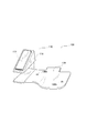
- An explanatory view about a footrest of a modification is shown.
- FIG. 1 shows a rough configuration of a vehicle 1 equipped with an automatic driving control system 200 of the present embodiment.
- the vehicle 1 of this embodiment is equipped with an automatic driving control device 10 and a driving information output device 100 that constitute a part of the automatic driving control system 200.
- the vehicle 1 includes an in-vehicle camera 2 that captures an image of the traveling direction, a navigation system (hereinafter referred to as a navigation system 3) that indicates a route to a preset destination, and an accelerator pedal actuator 4m that drives the accelerator pedal 4.
- a brake pedal actuator 5m for driving the brake pedal 5 and a steering handle actuator 6m for driving the steering handle 6 are also mounted.
- the automatic driving control device 10 detects the situation around the vehicle 1 based on the captured image obtained by the in-vehicle camera 2, and follows the route indicated by the navigation system 3 to the accelerator pedal actuator 4m and the brake pedal actuator 5m. The automatic operation is executed by driving the steering handle actuator 6m.
- the automatic operation control device 10 is described as detecting the surrounding situation exclusively using the image taken by the in-vehicle camera 2, but a sonar (not shown)
- the surrounding situation may be detected using a radar or a radar.
- the automatic operation control device 10 drives the accelerator pedal actuator 4m, the brake pedal actuator 5m, and the steering handle actuator 6m before executing the driving operation (hereinafter referred to as driving information). Is output toward the driving information output device 100.
- the driving information output device 100 includes a driving information acquisition unit 101 that receives driving information output from the automatic driving control device 10 and a footrest 110 mounted at the foot of the seat 7 on the driver's seat side.
- the footrest 110 according to the present embodiment is movable at the portion where the occupant places his / her foot.
- FIG. 2 shows a rough configuration of the automatic operation control system 200 of the present embodiment.
- the automatic driving control system 200 of this embodiment includes an automatic driving control device 10 and an driving information output device 100.
- the automatic operation control device 10 includes a driving operation determination unit 11, a driving operation control unit 13, and an operation information output unit 12.
- the driving operation determination unit 11 determines the driving operation of the vehicle 1 based on the situation around the vehicle 1 detected using the in-vehicle camera 2 and the like, and information on the route to the destination acquired from the navigation system 3. .
- the driving operation of the vehicle 1 means the types of driving operations such as acceleration and deceleration, left steering and right steering of the vehicle 1 and the operation amounts of these driving operations.
- the driving operation control unit 13 controls the accelerator pedal actuator 4m, the brake pedal actuator 5m, and the steering handle actuator 6m according to the driving operation determined by the driving operation determination unit 11.
- the driving information output unit 12 drives the driving operation contents (that is, driving information) before the driving operation control unit 13 controls the accelerator pedal actuator 4m, the brake pedal actuator 5m, and the steering handle actuator 6m. Obtained from the determination unit 11 and output toward the driving information output device 100.
- the driving information output device 100 of the present embodiment includes a driving information acquisition unit 101, a footrest 110, and the like.
- the driving information acquisition unit 101 receives the driving information from the driving information output unit 12, the driving information acquisition unit 101 outputs the driving information to the footrest 110.
- the footrest 110 the part on which the driver puts his / her foot (a footrest part described later) is movable, and this part can be moved based on the driving information. This point will be described in detail later.
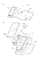
- FIG. 3 (a) and 3 (b) show the rough internal structure of the footrest 110 of this embodiment.
- the footrest 110 of this embodiment is provided movably with respect to the main body 111 placed on the floor surface in front of the seat 7 on the driver's seat side and the main body 111.
- An occupant sitting on the driver's seat 7 is naturally placed on the footrest 112.
- a floor mounting plate 130 having a large area is provided integrally with the main body 111 on the bottom surface side of the main body 111.
- the floor mounting plate 130 is provided with mounting holes 130h at two locations. By attaching the floor mounting plate 130 to the floor surface of the vehicle 1 on the driver seat side at these two locations, the floor mounting plate 130 can be attached to the feet on the driver seat side.
- a footrest 110 can be attached.
- the footrest 110 of the present embodiment will be described on the assumption that the main body 111 and the floor mounting plate 130 are integrally formed of a resin material. However, the main body 111 and the floor mounting plate 130 are formed as separate parts. You may keep it. Even in such a case, if the main body 111 is attached to the floor mounting plate 130 using screws or the like, the footrest 110 is attached by attaching the floor mounting plate 130 to the floor surface on the driver's seat side of the vehicle 1. Can do.
- FIG. 3B shows a rough internal structure of the footrest 110 of this embodiment.
- the footrest 110 of the present embodiment includes a main body portion 111 provided with a floor mounting plate 130 on the bottom surface side, a footrest portion 112 on which a driver's feet are placed, and a drive portion 120 that moves the footrest portion 112. ing.
- a large concave portion 111a is formed on the upper surface side of the main body 111, and the driving unit 120 is accommodated in the concave portion 111a through a substrate 113 made of metal and formed in a rectangular shape.
- the board 113 is formed with a screw hole 113h for screwing the drive unit 120 and a pair of convex portions 113r.
- a convex portion 113p is projected on the back side when the rectangular substrate 113 is viewed in the longitudinal direction. The reason why the convex portions 113r and the convex portions 113p are provided will be described later.
- the footrest portion 112 is formed of a metal plate member, and is formed by bending the left and right ends of the top plate 112a when viewed from the longitudinal direction of the top plate 112a and the top plate 112a.
- Side plate 112b when viewed from the longitudinal direction, the end on the back side of the top plate 112a is also bent to form the front plate 112c.
- the side plate 112b and the front plate 112c are members that ensure strength against bending and twisting of the top plate 112a. For this reason, since the footrest part 112 can be formed by a thin plate member, weight reduction can be achieved. Alternatively, the weight can be reduced by forming the footrest portion 112 using a hard resin material.
- the top plate 112a is attached to the upper surface of the drive unit 120 by screws (not shown). As a result, the top plate 112a is stored in the recess 111a of the main body 111 with the upper portion of the top plate 112a protruding (see FIG. 3A).
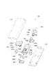
- FIG. 4 is an exploded view showing the internal structure of the drive unit 120 of this embodiment.
- the drive unit 120 has a structure in which various parts are assembled to a motor case 122 formed in a rectangular parallelepiped shape having a hollow inside.
- Rotating shafts 122r that rotate the motor case 122 in the roll direction project from the center positions of the front and back end faces when the motor case 122 is viewed in the longitudinal direction.
- a rear bearing 126 is attached to the front rotating shaft 122r.
- the rotation stop part 126s of the footrest part 112 protrudes. The reason why the rotation stop portion 126s is provided will be described later.
- a reduction gear 123 is attached to the inner rotary shaft 122r.
- a front bearing portion 125 is attached to the reduction gear 123 via a roll motion servo motor 124 that rotates the motor case 122 in the roll direction. It is attached.
- the rear side bearing part 126, the speed reducer 123, and the front side bearing part 125 are attached to the board
- a pitch motion servo motor 122m that rotates the motor case 122 in the pitch direction is mounted inside the motor case 122, and rotating shafts 122p project from the left and right side surfaces of the motor case 122.
- the upper surface rotating part 121 is attached to the upper surface of the motor case 122 so that the attaching part 121c is engaged with the left and right rotating shafts 122p.
- a gear portion 121b corresponding to a quarter circumference of a large gear projects from the lower surface side of the rectangular upper surface plate 121a, and further, mounting portions 121c are provided on both sides of the gear portion 121b.
- the gear portion 121b that protrudes from the lower surface of the upper surface plate 121a is attached to the drive shaft of the pitch motion servomotor 122m. Meshed with the gear 122g.
- the footrest portion 112 is screwed to the upper surface plate 121a with a screw (not shown).
- the footrest 110 of the present embodiment having the above-described structure can change the inclination of the footrest portion 112 by driving the pitch motion servomotor 122m or the roll motion servomotor 124.
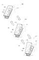
- the footrest 112 can be rotated in the pitch direction with the pitch motion rotation axis Axp as the rotation axis. 5 (a), 5 (b) and 5 (c), when the pitch servomotor 122m is driven, the upper surface rotating unit 121 rotates in the pitch direction with respect to the motor case 122. A state in which the placing portion 112 rotates in the pitch direction is shown.
- the footrest 112 can be rotated in the roll direction by driving the roll motion servo motor 124.
- the roll motion rotation axis Axr see FIG. 4 as the rotation axis. The state of rotating in the roll direction together with the motor case 122 and the upper surface rotating part 121 is shown.
- the automatic driving control device 10 tilts the footrest portion 112 of the footrest 110 in the pitch direction or the roll direction, so that the occupant sitting on the seat 7 on the driver's seat side does not feel uncomfortable. I am driving automatically.
- FIG. 7 shows a flowchart of the automatic driving control process executed by the automatic driving control device 10 of the present embodiment.
- the situation around the vehicle 1 is acquired (S100).
- the surrounding situation is acquired by analyzing a captured image obtained by the in-vehicle camera 2, but the present invention is not limited thereto, and a sonar or a radar is mounted on the vehicle 1, and these are used. You may acquire the surrounding situation.
- Whether or not a warning is necessary can be determined, for example, by analyzing a captured image obtained by the in-vehicle camera 2 or based on the output of a sonar or radar.
- a warning is issued by vibrating the footrest portion 112 of the footrest 110 (S102).
- the footrest portion 112 is vibrated by driving the roll motion servomotor 124 or the pitch motion servomotor 122m.
- a vibrator may be mounted on the footrest 110 separately from the roll motion servomotor 124 and the pitch motion servomotor 122m, and the footrest portion 112 may be vibrated by driving the vibrator.
- the content of the automatic driving operation is determined (S103). For example, when the destination is set for the navigation system 3, the accelerator pedal 4, the brake pedal 5, and the like are based on the route information indicated by the navigation system 3 and the situation around the vehicle 1. Whether or not to operate the steering handle 6 and the operation amount are determined.
- the content of the automatic driving operation determined in this way corresponds to “driving information” of the present invention.
- the footrest part 112 of the footrest 110 is tilted forward by driving the pitch motion servomotor 122m according to the degree of acceleration (S105).
- “inclined forward” refers to the pitch direction so that the tip on the back side of the footrest portion 112 is lowered when viewed from the occupant (driver during non-automatic driving) sitting on the seat 7 on the driver's seat side. The operation to rotate.
- the content of the automatic driving operation is not acceleration (S104: no)
- the footrest 112 of the footrest 110 is tilted backward by driving the pitch motion servomotor 122m according to the degree of deceleration (S107).
- backward tilt refers to rotation in the pitch direction so that the tip on the back side of the footrest portion 112 becomes higher when viewed from the occupant (driver during non-automatic driving) sitting on the seat 7 on the driver's seat side. Say the action to move.
- the pitch motion servomotor 122m is not driven. As a result, the footrest portion 112 of the footrest 110 is kept from tilting in the pitch direction.
- right steering the content of the automatic driving operation determined in S103 is steering of the steering handle 6 in the right direction (hereinafter referred to as right steering) (S108).
- right steering the roll moving servo motor 124 is driven according to the steering amount of the steering handle 6 to tilt the footrest portion 112 of the footrest 110 to the right (S109).
- “inclined to the right” means an operation of rotating in the roll direction so that the right side of the footrest portion 112 is lowered when viewed from the occupant (driver during non-automatic driving) sitting on the seat 7 on the driver's seat side.
- the roll moving servo motor 124 is driven according to the steering amount to tilt the footrest part 112 of the footrest 110 to the left (S111).
- “inclined to the left” refers to an operation of rotating in the roll direction so that the right side of the footrest 112 is lowered when viewed from the occupant sitting on the seat 7 on the driver's seat (driver during non-automatic driving).
- the roll servomotor 124 is not driven. As a result, the footrest portion 112 of the footrest 110 is kept from tilting in the roll direction.
- the driver can seat the seat 7 on the driver seat side even during the automatic driving so that the driving can be changed whenever the automatic driving control device 10 cannot cope. Is required to be seated. Therefore, when the footrest portion 112 of the footrest 110 is moved as described above, the movement is recognized by the occupant sitting on the seat 7 on the driver's seat side, and the content is transmitted to the occupant before the automatic driving operation is performed. be able to.
- the automatic driving control device 10 executes the automatic driving operation by driving the accelerator pedal actuator 4m, the brake pedal actuator 5m, and the steering handle actuator 6m in accordance with the contents determined in S103 (S112).
- the automatic driving control device 10 determines whether or not the automatic driving is to be ended (S113).
- the process returns to the top of the process and the surrounding conditions of the vehicle 1 are acquired.
- the subsequent series of processes S101 to S112 are executed.
- the automatic driving control process of FIG. 7 is ended.
- the footrest 112 rotates in the pitch direction before the vehicle 1 accelerates or decelerates (see FIG. 5). Further, before the vehicle 1 turns left or right, the footrest 112 rotates in the roll direction (see FIG. 6). For this reason, the occupant sitting on the seat 7 on the driver's seat side can recognize in advance the content of the automatic driving operation to be performed in the future, so that it is possible to automatically drive without causing the occupant to feel uncomfortable.
- the motion of the roll motion servo motor 124 is decelerated by the speed reducer 123 and transmitted to the motor case 122.
- the motion of the pitch motion servo motor 122m is controlled by the gear 122g.
- the gear portion 121b are decelerated and transmitted to the upper surface plate 121a.
- the pair of convex portions 113r are projected from the substrate 113, and when the footrest portion 112 rotates in the roll direction, the side plate 112b becomes the convex portion 113r. It will come into contact with and will not rotate any further. For this reason, even when the occupant sitting in the driver's seat steps on his / her foot and the footrest portion 112 rotates in the roll direction, a situation where the roll motion servo motor 124 rotates beyond the movable range and is damaged is avoided. be able to.
- the convex part 113r of a present Example corresponds to the "roll movement restriction
- the footrest 112 does not rotate excessively. That is, the protrusion 113p protrudes from the back side of the board 113 when viewed from the driver's seat side, and the footrest portion 112 tilts forward beyond the allowable range (that is, the back side is low when viewed from the driver's seat side).
- the front plate 112c of the footrest portion 112 abuts on the convex portion 113p so that it does not rotate any further.
- the rear bearing portion 126 is provided with a rotation stop portion 126s, and the footrest portion 112 tilts backward beyond an allowable range (that is, viewed from the driver seat side).
- the rear side becomes higher
- the rear end surface of the footrest portion 112 abuts against the rotation stop portion 126s so that it does not rotate any further.
- the pitch motion servomotor 122m rotates beyond the movable range and is damaged is avoided. be able to.
- each of the convex part 113p and the rotation stop part 126s of a present Example corresponds to the "pitch movement restriction
- the footrest 110 of the present embodiment rotates the footrest portion 112 in the pitch direction or the roll direction with a large force in a state where the feet of the occupant sitting on the driver's seat are placed, and thus the footrest 110 has a large force.
- the main body 111 of the footrest 110 needs to be firmly fixed so that it does not move even when a large force is applied.
- the footrest has a narrow shape, and the floor surface of the portion where the footrest on the driver's seat side of the vehicle 1 is attached is formed by a curved surface. For this reason, it is generally difficult to fix the footrest firmly.
- the footrest 110 of this embodiment is provided with a floor mounting plate 130 having a large area on the bottom surface side of the main body 111.
- the floor mounting plate 130 is mounted in a state of covering the floor surface on the driver's seat side by mounting the floor mounting plate 130 on the floor surface on the driver's seat side through the mounting hole 130h shown in FIG. For this reason, since the main body 111 of the footrest 110 is supported by the floor mounting plate 130 having a large area, it can be firmly fixed to the floor surface on the driver's seat side formed by a curved surface. .
- the floor mounting plate 130 has a large area, the interval between the plurality of mounting holes 130h for mounting the floor mounting plate 130 to the floor surface can be sufficiently increased.
- the floor mounting plate 130 can be assembled to the floor surface of the vehicle 1 with high accuracy, so that the footrest 110 can also be assembled to the floor surface of the vehicle 1 with high accuracy.
- the footrest 110 can also be assembled, so that the assembling work can be made more efficient.
- the footrest 110 of the above-described embodiment has been described on the assumption that the main body 111 and the floor mounting plate 130 are integrally formed. In this way, even when a large force is applied to the footrest portion 112, the main body portion 111 is not detached from the floor mounting plate 130.
- the main body portion 111 and the floor mounting plate 130 are formed separately, and the main body portion 111 and the floor mounting plate are bonded by a method such as screwing or bonding. 130 may be combined.
Landscapes
- Physics & Mathematics (AREA)
- General Physics & Mathematics (AREA)
- Control Of Driving Devices And Active Controlling Of Vehicle (AREA)
- Traffic Control Systems (AREA)
- Passenger Equipment (AREA)
Abstract
車両の周囲の状況に基づいて車両の運転動作の内容を決定すると、車両の運転席側に設けられたフットレストの足置き部を移動させることにより、決定した運転動作の内容を運転情報として出力する。こうすれば、自動運転動作の内容を運転者が予め認識することができる。このため、自動運転時の運転の仕方が運転者の運転の仕方とは異なっていても、運転者に違和感を与えることなく、車両を自動運転することが可能となる。加えて、フットレストの底面側には、運転席側の床面を覆った状態で床面に取り付けられるフロア取付板を設けておく。こうすれば、運転席側の床面にフロア取付板を取り付けることで、フットレストを車両に簡単に且つしっかりと取り付けることができる。
Description
本発明は、車両の周囲の状況に基づいて車両を自動運転する技術に関する。
今日では、車両が周囲の状況を把握しながら、走行中の車線を維持したり障害物を回避したりすることによって、車両の自動運転を実現する技術が開発されている。自動運転中は、車両に搭載されたコンピューター(以下、自動運転制御装置)が運転者に代わって車両を運転するので、運転制御装置による運転の仕方(例えばカーブ走行時や、障害物回避時のライン取り、加減速のタイミングや程度など)に運転者が違和感を覚えることがしばしば存在する。
そこで、運転制御装置による運転の仕方を、標準的な運転者による運転の仕方にできるだけ近付けようとする技術が提案されている(たとえば特許文献1)。
そこで、運転制御装置による運転の仕方を、標準的な運転者による運転の仕方にできるだけ近付けようとする技術が提案されている(たとえば特許文献1)。
しかし、提案されている技術では、自動運転中に運転者に与える違和感を十分に緩和することができないという問題があった。これは、運転の仕方は周囲の状況や運転者の個性などによっても変わるので、自動運転制御装置による運転の仕方を運転者の運転の仕方に近付けようとしても限界があるためである。
この発明は、従来技術が有する上述した問題に鑑みてなされたものであり、運転者に違和感を与えることなく、車両の自動運転を可能とする技術の提供を目的とする。
上述した問題を解決するために本発明の自動運転制御システム、運転情報出力装置、およびフットレストの、開示される一つの態様は、車両の周囲の状況に基づいて車両の運転動作の内容を決定すると、車両の運転席側に設けられたフットレストの足置き部を移動させることにより、決定した運転動作の内容を運転情報として出力する。
こうすれば、自動運転動作の内容を運転者が予め認識することができる。このため、自動運転時の運転の仕方が運転者の運転の仕方とは異なっていても、運転者に違和感を与えることなく、車両を自動運転することが可能となる。
こうすれば、自動運転動作の内容を運転者が予め認識することができる。このため、自動運転時の運転の仕方が運転者の運転の仕方とは異なっていても、運転者に違和感を与えることなく、車両を自動運転することが可能となる。
加えて、フットレストには、底面側にフロア取付板が設けられており、このフロア取付板は、運転席側の床面を覆った状態で床面に取り付けられる。
このため、運転席側の床面にフロア取付板を取り付けることで、フットレストを車両に簡単に取り付けることができる。更に、フットレストはフロア取付板を介して広い面積の床面で支えられた状態となる。このため、運転席の乗員が足を載せた状態で足置き部を移動させても、フットレストの位置や姿勢がぐらつかないように保持しておくことが可能となる。
このため、運転席側の床面にフロア取付板を取り付けることで、フットレストを車両に簡単に取り付けることができる。更に、フットレストはフロア取付板を介して広い面積の床面で支えられた状態となる。このため、運転席の乗員が足を載せた状態で足置き部を移動させても、フットレストの位置や姿勢がぐらつかないように保持しておくことが可能となる。
更に加えて、以下の理由から、フットレストの取付精度を確保することも容易となる。一般に、ある部材を別の部材に取り付ける際には、ボスやネジ穴を利用するなど、何らかの方法を用いて位置決めした状態で取り付けられる。また、1箇所で位置決めしたのでは、位置決めした位置を中心として、一方の部材が他方の部材に対して回転してしまうので、複数箇所で位置決めしておく必要がある。このため、ある部材を精度良く位置決めして取り付けるためには、取り付ける部材および取り付けられる部材のそれぞれについて、少なくとも複数箇所を、十分な精度が出るように製造しておく必要がある。
ここで、フロア取付板は床面の広い面積を覆うように取り付けられる。このため、床面に対してフロア取付板を位置決めするための複数の位置決め箇所を、十分に離れた位置に設けることができる。そして、十分に離れた位置で位置決めしてやれば、床面に対するフロア取付板の取付精度を容易に確保することができ、その結果、フットレストの床面に対する取付精度も容易に確保することが可能となる。
添付した図面において、
本実施例の自動運転制御システムおよび運転情報出力装置を搭載した車両の説明図を示す。
本実施例の自動運転制御システムおよび運転情報出力装置の大まかな構成を示すブロック図を示す。
(a)及び(b)は、本実施例の運転情報出力装置で採用された本実施例のフットレストの大まかな内部構造を示した説明図を示す。
本実施例のフットレストに搭載された駆動部の構造を示す分解組立図を示す。
(a)、(b)及び(c)は、本実施例のフットレストが足置き部をピッチ方向に回動させる様子を示した説明図を示す。
(a)、(b)及び(c)は、本実施例のフットレストが足置き部をロール方向に回動させる様子を示した説明図を示す。
本実施例の自動運転制御システムで実行される自動運転制御処理のフローチャートを示す。
変形例のフットレストについての説明図を示す。
以下では、上述した本願発明の内容を明確にするために実施例について説明する。
A.装置構成:
図1には、本実施例の自動運転制御システム200を搭載した車両1の大まかな構成が示されている。本実施例の車両1には、自動運転制御システム200の一部を構成する自動運転制御装置10や、運転情報出力装置100が搭載されている。更に、車両1には、進行方向の画像を撮影する車載カメラ2や、予め設定された目的地への経路を示すナビゲーションシステム(以下、ナビシステム3)、アクセルペダル4を駆動するアクセルペダルアクチュエーター4m、ブレーキペダル5を駆動するブレーキペダルアクチュエーター5m、ステアリングハンドル6を駆動するステアリングハンドルアクチュエーター6mなども搭載されている。
A.装置構成:
図1には、本実施例の自動運転制御システム200を搭載した車両1の大まかな構成が示されている。本実施例の車両1には、自動運転制御システム200の一部を構成する自動運転制御装置10や、運転情報出力装置100が搭載されている。更に、車両1には、進行方向の画像を撮影する車載カメラ2や、予め設定された目的地への経路を示すナビゲーションシステム(以下、ナビシステム3)、アクセルペダル4を駆動するアクセルペダルアクチュエーター4m、ブレーキペダル5を駆動するブレーキペダルアクチュエーター5m、ステアリングハンドル6を駆動するステアリングハンドルアクチュエーター6mなども搭載されている。
自動運転制御装置10は、車載カメラ2で得られた撮影画像に基づいて車両1の周囲の状況を検出しながら、ナビシステム3によって示された経路に従って、アクセルペダルアクチュエーター4mや、ブレーキペダルアクチュエーター5m、ステアリングハンドルアクチュエーター6mを駆動することによって自動運転を実行する。
尚、本実施例では、説明が複雑になることを回避する目的で、自動運転制御装置10はもっぱら車載カメラ2による撮影画像を用いて周囲の状況を検出するものとして説明するが、図示しないソナーやレーダーなどを用いて周囲の状況を検出しても良い。
また、自動運転制御装置10は、アクセルペダルアクチュエーター4mや、ブレーキペダルアクチュエーター5m、ステアリングハンドルアクチュエーター6mを駆動して運転操作を実行するに先立って、その運転操作の内容(以下、運転情報と称する)を、運転情報出力装置100に向かって出力する。
運転情報出力装置100は、自動運転制御装置10から出力された運転情報を受け取る運転情報取得部101や、運転席側のシート7の足元に搭載されたフットレスト110を備えている。詳細には後述するが、本実施例のフットレスト110は、乗員が足を載せる部分が可動式となっている。
図2には、本実施例の自動運転制御システム200の大まかな構成が示されている。図示されるように、本実施例の自動運転制御システム200は、自動運転制御装置10と、運転情報出力装置100とを備えている。
このうちの自動運転制御装置10は、運転動作決定部11や、運転動作制御部13、運転情報出力部12を備えている。
このうちの自動運転制御装置10は、運転動作決定部11や、運転動作制御部13、運転情報出力部12を備えている。
運転動作決定部11は、車載カメラ2等を用いて検出した車両1の周囲の状況と、ナビシステム3から取得した目的地への経路の情報とに基づいて、車両1の運転動作を決定する。ここで、車両1の運転動作とは、車両1の加速や減速、左操舵や右操舵といった運転操作の種類と、それら運転操作の操作量とを意味している。
運転動作制御部13は、運転動作決定部11で決定された運転動作に従って、アクセルペダルアクチュエーター4mや、ブレーキペダルアクチュエーター5m、ステアリングハンドルアクチュエーター6mを制御する。
また、運転情報出力部12は、運転動作制御部13がアクセルペダルアクチュエーター4mや、ブレーキペダルアクチュエーター5m、ステアリングハンドルアクチュエーター6mを制御するに先立って、運転動作の内容(すなわち、運転情報)を運転動作決定部11から取得して、運転情報出力装置100に向かって出力する。
また、本実施例の運転情報出力装置100は、運転情報取得部101や、フットレスト110などを備えている。
運転情報取得部101は、運転情報出力部12から運転情報を受け取ると、フットレスト110に出力する。上述したようにフットレスト110は、運転者が足を載せる部分(後述する足置き部)が可動式となっており、この部分を、運転情報に基づいて移動させることが可能となっている。この点については、後ほど詳しく説明する。
運転情報取得部101は、運転情報出力部12から運転情報を受け取ると、フットレスト110に出力する。上述したようにフットレスト110は、運転者が足を載せる部分(後述する足置き部)が可動式となっており、この部分を、運転情報に基づいて移動させることが可能となっている。この点については、後ほど詳しく説明する。
図3(a)及び(b)には、本実施例のフットレスト110の大まかな内部構造が示されている。図3(a)に示されるように、本実施例のフットレスト110は、運転席側のシート7の前方の床面に載置される本体部111と、本体部111に対して可動に設けられた足置き部112とを備えている。運転席側のシート7に座った乗員は、自然に、足置き部112の上に足を載せた状態となる。更に、本体部111の底面側には、広い面積を有するフロア取付板130が、本体部111と一体に設けられている。このフロア取付板130には、2箇所に取付穴130hが設けられており、この2箇所でフロア取付板130を、車両1の運転席側の床面に取り付けることによって、運転席側の足元にフットレスト110を取り付けることが可能となっている。
尚、本実施例のフットレスト110は、本体部111とフロア取付板130とが樹脂材料によって一体に成型されているものとして説明するが、本体部111とフロア取付板130とを別部品として形成しておいてもよい。このような場合でも、ネジなどを用いて、本体部111をフロア取付板130に取り付けておけば、車両1の運転席側の床面にフロア取付板130を取り付けることによって、フットレスト110を取り付けることができる。
図3(b)には、本実施例のフットレスト110の大まかな内部構造が示されている。本実施例のフットレスト110は、底面側にフロア取付板130が設けられた本体部111と、運転者の足が載せられる足置き部112と、足置き部112を移動させる駆動部120とを備えている。
本体部111の上面側には大きな凹部111aが形成されており、駆動部120は、金属製で長方形形状に形成された基板113を介して、凹部111a内に収納される。図示されるように、基板113には、駆動部120をネジ止めするためのネジ穴113hや、一対の凸部113rが形成されている。更に、長方形の基板113を長手方向に見て奥側には、凸部113pが突設されている。これら凸部113rや凸部113pが設けられている理由については後述する。
また、足置き部112は、金属製の板部材によって形成されており、長方形形状の天板112aと、天板112aの長手方向から見て、天板112aの左右の端部を折り曲げることによって形成された側板112bとを備えている。更に、本実施例では、長手方向から見て、天板112aの奥側の端部も折り曲げられて前板112cが形成されている。これら側板112bや前板112cは、天板112aの曲げや捻りに対する強度を確保する部材となっている。このため、足置き部112は、薄い板部材によって形成することができるので、軽量化を図ることができる。あるいは、硬質樹脂材料を用いて足置き部112を形成することによって、軽量化を図ることも可能である。
そして、天板112aが図示しないネジによって駆動部120の上面に取り付けられる。その結果、天板112aの上側部分が突出した状態で、本体部111の凹部111a内に天板112aが収納される(図3(a)を参照のこと)。
図4には、本実施例の駆動部120の内部構造を示す分解組立図が示されている。図示されるように駆動部120は、内部が空洞の直方体形状に形成されたモーターケース122に、様々な部品が組み付けられた構造となっている。
モーターケース122を長手方向に見て手前側および奥側の端面の中央位置には、モーターケース122をロール方向に回転させる回転軸122rが突設されている。そして、手前側の回転軸122rには、後側軸受部126が取り付けられている。尚、後側軸受部126の上部からは、足置き部112の回止部126sが突設されている。回止部126sが設けられている理由については後述する。また、奥側の回転軸122rには、減速器123が取り付けられており、その減速器123には、モーターケース122をロール方向に回動させるロール動サーボモーター124を介して前側軸受部125が取り付けられている。そして、後側軸受部126、減速器123、および前側軸受部125は、図示しないネジによって基板113に取り付けられる。
また、モーターケース122の内部には、モーターケース122をピッチ方向に回転させるピッチ動サーボモーター122mが搭載されており、モーターケース122の左右の側面には、回転軸122pが突設されている。
更に、モーターケース122の上面には、左右の回転軸122pに取付部121cを係合させるようにして、上面回転部121が取り付けられている。この上面回転部121は、矩形形状の上面板121aの下面側に、大きな歯車の1/4円周分に相当する歯車部121bが突設され、更に歯車部121bの両側には、取付部121cが突設された形状となっている。そして、取付部121cを、モーターケース122の左右の側面に突設する回転軸122pに取り付けると、上面板121aの下面から突設する歯車部121bが、ピッチ動サーボモーター122mの駆動軸に取り付けられた歯車122gに噛合するようになっている。足置き部112は、図示しないネジによって上面板121aにネジ止めされる。
以上のような構造を有する本実施例のフットレスト110は、ピッチ動サーボモーター122m、あるいはロール動サーボモーター124を駆動することによって、足置き部112の傾きを変更することができる。
例えば、ピッチ動サーボモーター122mを駆動すれば、ピッチ動回転軸Axpを回転軸として、足置き部112をピッチ方向に回動させることができる。図5(a)、(b)及び(c)には、ピッチ動サーボモーター122mを駆動することによって、上面回転部121がモーターケース122に対してピッチ方向に回動し、その結果として、足置き部112がピッチ方向に回動する様子が示されている。
また、足置き部112をピッチ方向に回動させた状態でも、ロール動サーボモーター124を駆動すすることによって、足置き部112をロール方向に回動させることができる。図6(a)、(b)及び(c)には、ロール動サーボモーター124を駆動することによって、ロール動回転軸Axr(図4を参照のこと)を回転軸として、足置き部112が、モーターケース122および上面回転部121と一緒にロール方向に回動する様子が示されている。
本実施例の自動運転制御装置10は、フットレスト110の足置き部112を、ピッチ方向あるいはロール方向に傾けることによって、運転席側のシート7に座った乗員に違和感を与えることなく、車両1を自動運転している。
B.自動運転制御処理:
図7には、本実施例の自動運転制御装置10が実行する自動運転制御処理のフローチャートが示されている。
図示されるように、自動運転制御処理では先ず始めに、車両1の周囲の状況を取得する(S100)。本実施例では、車載カメラ2によって得られた撮影画像を解析することによって周囲の状況を取得するものとしているが、これに限らず、車両1にソナーやレーダーを搭載しておき、これらを用いて周囲の状況を取得しても良い。
図7には、本実施例の自動運転制御装置10が実行する自動運転制御処理のフローチャートが示されている。
図示されるように、自動運転制御処理では先ず始めに、車両1の周囲の状況を取得する(S100)。本実施例では、車載カメラ2によって得られた撮影画像を解析することによって周囲の状況を取得するものとしているが、これに限らず、車両1にソナーやレーダーを搭載しておき、これらを用いて周囲の状況を取得しても良い。
続いて、車両1の乗員に対して警告が必要か否かを判断する(S101)。警告が必要か否かについては、例えば、車載カメラ2によって得られた撮影画像を解析して、あるいはソナーやレーダーの出力に基づいて判断することができる。
その結果、警告が必要と判断した場合は(S101:yes)、フットレスト110の足置き部112を振動させることによって警告する(S102)。本実施例では、ロール動サーボモーター124、あるいはピッチ動サーボモーター122mを駆動することによって足置き部112を振動させる。もちろん、ロール動サーボモーター124やピッチ動サーボモーター122mとは別に、バイブレーターをフットレスト110に搭載しておき、バイブレーターを駆動することによって足置き部112を振動させても良い。
これに対して、警告が不要であった場合は(S101:no)、自動運転動作の内容を決定する(S103)。例えば、ナビシステム3に対して目的地が設定されている場合には、ナビシステム3によって示された経路の情報と、車両1の周囲の状況とに基づいて、アクセルペダル4やブレーキペダル5、ステアリングハンドル6を操作するか否か、および操作量を決定する。
あるいは、先行車両を追走するように設定されている場合には、車載カメラ2によって得られた撮影画像に基づいて、先行車両の位置を含めた車両1の周囲の状況を検出することによって、アクセルペダル4やブレーキペダル5、ステアリングハンドル6を操作するか否か、および操作量を決定する。
尚、以下の説明では、こうして決定された自動運転動作の内容が、本発明の「運転情報」に対応する。
尚、以下の説明では、こうして決定された自動運転動作の内容が、本発明の「運転情報」に対応する。
そして、決定した自動運転動作の内容が加速か否かを判断する(S104)。その結果、加速であった場合は(S104:yes)、加速の程度に応じてピッチ動サーボモーター122mを駆動することにより、フットレスト110の足置き部112を前傾させる(S105)。ここで「前傾」とは、運転席側のシート7に座っている乗員(非自動運転時の運転者)からみて、足置き部112の奥側の先端が低くなるように、ピッチ方向に回動させる動作を言う。
これに対して、自動運転動作の内容が加速ではなかった場合は(S104:no)、減速か否かを判断する(S106)。その結果、減速であった場合は(S106:yes)、減速の程度に応じてピッチ動サーボモーター122mを駆動することにより、フットレスト110の足置き部112を後傾させる(S107)。ここで「後傾」とは、運転席側のシート7に座っている乗員(非自動運転時の運転者)からみて足置き部112の奥側の先端が高くなるように、ピッチ方向に回動させる動作を言う。
また、自動運転動作の内容が加速でも減速でも無かった場合は(S104:no)、ピッチ動サーボモーター122mは駆動しない。この結果、フットレスト110の足置き部112は、ピッチ方向には傾かない状態が保たれる。
続いて、S103で決定した自動運転動作の内容が、ステアリングハンドル6の右方向への操舵(以下、右操舵)か否かを判断する(S108)。その結果、右操舵であった場合は(S108:yes)、ステアリングハンドル6の操舵量に応じてロール動サーボモーター124を駆動することにより、フットレスト110の足置き部112を右傾させる(S109)。ここで「右傾」とは、運転席側のシート7に座っている乗員(非自動運転時の運転者)からみて、足置き部112の右側が低くなるように、ロール方向に回動させる動作を言う。
これに対して、自動運転動作の内容が右操舵ではなかった場合は(S108:no)、ステアリングハンドル6の左方向への操舵(以下、左操舵)か否かを判断する(S110)。その結果、左操舵であった場合は(S110:yes)、操舵量に応じてロール動サーボモーター124を駆動することにより、フットレスト110の足置き部112を左傾させる(S111)。ここで「左傾」とは、運転席側のシート7に座っている乗員(非自動運転時の運転者)からみて、足置き部112の右側が低くなるように、ロール方向に回動させる動作を言う。
また、自動運転動作の内容が右操舵でも左操舵でも無かった場合は(S110:no)、ロール動サーボモーター124は駆動しない。この結果、フットレスト110の足置き部112は、ロール方向には傾かない状態が保たれる。
自動運転中は乗員が車両1を運転することはないが、自動運転制御装置10が対応しきれない事態が生じた時にはいつでも運転を替われるように、自動運転中も運転席側のシート7には乗員が座っていることが要請される。従って、以上のようにしてフットレスト110の足置き部112を動かすと、その動きは運転席側のシート7に座っている乗員に認識されて、自動運転動作の実行前にその内容を乗員に伝えることができる。
その後、自動運転制御装置10は、S103で決定した内容に従って、アクセルペダルアクチュエーター4mや、ブレーキペダルアクチュエーター5m、ステアリングハンドルアクチュエーター6mを駆動することによって、自動運転動作を実行する(S112)。
続いて、自動運転制御装置10は自動運転を終了するか否かを判断し(S113)、終了しない場合は(S113:no)、処理の先頭に戻って、車両1の周囲の状況を取得した後(S100)、続く上述した一連の処理(S101~S112)を実行する。そして、このような操作を繰り返しているうちに、自動運転を終了すると判断した場合は(S113:yes)、図7の自動運転制御処理を終了する。
本実施例の自動運転制御システム200を搭載した車両1では、車両1が加速または減速する前に、足置き部112がピッチ方向に回動する(図5参照)。また、車両1が左旋回または右旋回する前には、足置き部112がロール方向に回動する(図6参照)。このため、運転席側のシート7に座った乗員は、これから行われる自動運転動作の内容を予め認識することができるので、乗員に違和感を与えることなく自動運転することが可能となる。
ここで、フットレスト110の足置き部112には、運転席に座った乗員の足が載せられるので、足置き部112を動かそうとした時に大きな力が必要となる場合がある。そこで、本実施例のフットレスト110では、ロール動サーボモーター124の動きを減速器123で減速してモーターケース122に伝えるようになっており、同様に、ピッチ動サーボモーター122mの動きは、歯車122gと歯車部121bとの間で減速して上面板121aに伝えるようになっている。
もっとも、このように、ロール動サーボモーター124あるいはピッチ動サーボモーター122mの回転を減速して足置き部112に伝えると、運転席に座った乗員が足を踏ん張るなどした場合に、これらのサーボモーターを破損させる虞がある。これは、運転席に座った乗員が足を踏ん張るなどして足置き部112を回転させると、その回転が増大して伝わるので、これらサーボモーターの可動範囲を超えて、ロール動サーボモーター124あるいはピッチ動サーボモーター122mを回転させてしまう虞があるためである。
そこで、本実施例のフットレスト110では、図3に示したように、基板113に一対の凸部113rが突設されており、足置き部112がロール方向に回転すると、側板112bが凸部113rに当接して、それ以上に回転しないようになっている。
このため、運転席に座った乗員が足を踏ん張るなどして、足置き部112がロール方向に回転した場合でも、ロール動サーボモーター124が可動範囲を超えて回転して破損する事態を回避することができる。
尚、本実施例の凸部113rは、本発明の「ロール動制限部」に該当する。
このため、運転席に座った乗員が足を踏ん張るなどして、足置き部112がロール方向に回転した場合でも、ロール動サーボモーター124が可動範囲を超えて回転して破損する事態を回避することができる。
尚、本実施例の凸部113rは、本発明の「ロール動制限部」に該当する。
同様に、足置き部112がピッチ方向に回転する場合でも、足置き部112が過大に回転しないようになっている。すなわち、運転席側から見て基板113の奥側には凸部113pが突設されており、足置き部112が許容範囲を超えて前傾する(すなわち、運転席側から見て奥側が低くなる)と、足置き部112の前板112cが凸部113pに当接して、それ以上に回転しないようになっている。
また、図4に示したように、後側軸受部126には回止部126sが突設されており、足置き部112が許容範囲を超えて後傾する(すなわち、運転席側から見て奥側が高くなる)と、足置き部112の後端面が回止部126sに当接して、それ以上に回転しないようになっている。
このため、運転席に座った乗員が足を踏ん張るなどして、足置き部112がピッチ方向に回転した場合でも、ピッチ動サーボモーター122mが可動範囲を超えて回転して破損する事態を回避することができる。
尚、本実施例の凸部113pおよび回止部126sのそれぞれは、本発明の「ピッチ動制限部」に該当する。
このため、運転席に座った乗員が足を踏ん張るなどして、足置き部112がピッチ方向に回転した場合でも、ピッチ動サーボモーター122mが可動範囲を超えて回転して破損する事態を回避することができる。
尚、本実施例の凸部113pおよび回止部126sのそれぞれは、本発明の「ピッチ動制限部」に該当する。
また、本実施例のフットレスト110は、運転席に座った乗員の足が載せられた状態で、足置き部112を大きな力でピッチ方向あるいはロール方向に回動させるので、フットレスト110にも大きな力が作用する。このため、フットレスト110の本体部111は、大きな力が作用しても動かないようにしっかりと固定しておく必要がある。
ところが、一般に、フットレストは幅の狭い形状であり、しかも、車両1の運転席側のフットレストが取り付けられる部分の床面は、曲面によって形成されている。このため、フットレストを、しっかりと固定しておくことは、一般的には難しい。
ところが、一般に、フットレストは幅の狭い形状であり、しかも、車両1の運転席側のフットレストが取り付けられる部分の床面は、曲面によって形成されている。このため、フットレストを、しっかりと固定しておくことは、一般的には難しい。
ところが、本実施例のフットレスト110は、本体部111の底面側に、広い面積を有するフロア取付板130が設けられている。そして、このフロア取付板130は、図3に示した取付穴130hで運転席側の床面に取り付けることによって、運転席側の床面を覆った状態で取り付けられる。
このため、フットレスト110の本体部111は、広い面積を有するフロア取付板130で支えられることになるので、曲面によって形成された運転席側の床面にも、しっかりと固定することが可能となる。
このため、フットレスト110の本体部111は、広い面積を有するフロア取付板130で支えられることになるので、曲面によって形成された運転席側の床面にも、しっかりと固定することが可能となる。
また、フロア取付板130は広い面積を有しているので、フロア取付板130を床面に取り付けるための複数の取付穴130hの間隔も十分に大きくすることができる。その結果、車両1の床面に対してフロア取付板130を精度良く組み付けることができるので、フットレスト110も車両1の床面に対して精度良く組み付けることが可能となる。
加えて、車両1の運転席側の床面に、単にフロア取付板130を組み付ければ、フットレスト110も組み付けることができるので、組み付け作業を効率化することも可能となる。
加えて、車両1の運転席側の床面に、単にフロア取付板130を組み付ければ、フットレスト110も組み付けることができるので、組み付け作業を効率化することも可能となる。
尚、上述した本実施例のフットレスト110は、本体部111とフロア取付板130とが一体に形成されているものとして説明した。このようにしておけば、足置き部112に大きな力が作用した場合でも、フロア取付板130から本体部111が外れることがない。もっとも、図8に例示した変形例のフットレスト150のように、本体部111とフロア取付板130とを別体に形成しておき、ネジ止めあるいは接着などの方法で、本体部111とフロア取付板130とを結合しても構わない。
以上、本実施例について説明したが、本発明は上記の実施例あるいは変形例に限られるものではなく、その要旨を逸脱しない範囲において種々の態様で実施することができる。
1…車両
2…車載カメラ
3…ナビシステム
4…アクセルペダル
5…ブレーキペダル
6…ステアリングハンドル
7…シート
10…自動運転制御装置
11…運転動作決定部
12…運転情報出力部
13…運転動作制御部
100…運転情報出力装置
101…運転情報取得部
110…フットレスト
111…本体部
112…足置き部
112a…天板
112b…側板
112c…前板
113p…凸部
113r…凸部
120…駆動部
121b…歯車部
122…モーターケース
122g…歯車
122m…ピッチ動サーボモーター
122p…回転軸
122r…回転軸
123…減速器
124…ロール動サーボモーター
125…前側軸受部
126…後側軸受部
126s…回止部
130…フロア取付板
130h…取付穴
150…フットレスト
200…自動運転制御システム
2…車載カメラ
3…ナビシステム
4…アクセルペダル
5…ブレーキペダル
6…ステアリングハンドル
7…シート
10…自動運転制御装置
11…運転動作決定部
12…運転情報出力部
13…運転動作制御部
100…運転情報出力装置
101…運転情報取得部
110…フットレスト
111…本体部
112…足置き部
112a…天板
112b…側板
112c…前板
113p…凸部
113r…凸部
120…駆動部
121b…歯車部
122…モーターケース
122g…歯車
122m…ピッチ動サーボモーター
122p…回転軸
122r…回転軸
123…減速器
124…ロール動サーボモーター
125…前側軸受部
126…後側軸受部
126s…回止部
130…フロア取付板
130h…取付穴
150…フットレスト
200…自動運転制御システム
Claims (8)
- 車両(1)の周囲の状況に基づいて該車両の運転動作を制御することによって自動運転を実現する自動運転制御装置(10)と、該自動運転中の運転動作の内容に関する運転情報を前記車両の乗員に対して出力する運転情報出力装置(100)とを備える自動運転制御システム(200)であって、
前記自動運転制御装置は、
前記車両の周囲の状況に基づいて前記運転動作の内容を決定する運転動作決定部(11)と、
前記決定された運転動作の内容に応じて、前記運転情報を前記運転情報出力装置に出力する運転情報出力部(12)と、
前記決定された運転動作の内容に従って、前記車両の運転動作を制御する運転動作制御部(13)とを備えており、
前記運転情報出力装置は、
前記車両の運転席側に設けられて、足置き部(112)を有するフットレスト(110、150)と、
前記フットレストに内蔵されて、前記運転情報出力部から出力される前記運転情報に応じて前記足置き部を移動させる駆動部(120)と、
前記フットレストの底面側に設けられて、前記車両の運転席側の床面を覆った状態で該床面に取り付けられるフロア取付板(130)とを備えている自動運転制御システム。 - 周囲の状況に基づいて自動運転可能な車両(1)に搭載されて、該自動運転中の運転動作の内容に関する運転情報を前記車両の乗員に対して出力する運転情報出力装置(100)であって、
前記自動運転中に前記車両の運転動作を制御する自動運転制御装置から、前記運転情報を取得する運転情報取得部(101)と、
前記車両の運転席側に設けられて、足置き部(112)を有するフットレスト(110、150)と、
前記フットレストに内蔵されて、運転情報出力部(12)から出力される前記運転情報に応じて前記足置き部を移動させる駆動部(120)と、
前記フットレストの底面側に設けられて、前記車両の運転席側の床面を覆った状態で該床面に取り付けられるフロア取付板(130)とを備える運転情報出力装置。 - 請求項2に記載の運転情報出力装置であって、
前記フットレストと前記フロア取付板とは一体に形成されていることを特徴とする運転情報出力装置。 - 請求項2または請求項3に記載の運転情報出力装置であって、
前記足置き部は、
長手方向を有する形状の天板(112a)と、
前記天板の裏面側で、且つ、該天板の前記長手方向に対して左端および右端の位置に、前記長手方向に延設された側板(112b)と、を有しており、
前記駆動部は、前記足置き部を、前記天板の前記長手方向に向かってロール方向に移動させる駆動部であり、
前記フットレストは、前記側板に当接することによって、前記足置き部の前記ロール方向の移動範囲を制限するロール動制限部(113r)を有することを特徴とする運転情報出力装置。 - 請求項4に記載の運転情報出力装置であって、
前記側板は、前記天板の前記長手方向に対して左右の部分を折り曲げることによって形成されていることを特徴とする運転情報出力装置。 - 請求項2ないし請求項5の何れか一項に記載の運転情報出力装置であって、
前記駆動部は、前記足置き部を、前記天板の前記長手方向に向かってピッチ方向に移動させる駆動部であり、
前記フットレストは、前記足置き部の一部に当接することによって、前記足置き部の前記ピッチ方向の移動範囲を制限するピッチ動制限部(113p、126s)を備えることを特徴とする運転情報出力装置。 - 車両の運転席に座った乗員が足を載せるためのフットレスト(110、150)であって、
前記乗員の足が載せられる足置き部と、
前記車両側からの制御に従って前記足置き部を移動させる駆動部と、
前記駆動部を内蔵する本体部(111)と、
前記本体部の底面側に設けられて、前記車両の運転席側の床面を覆った状態で該床面に取り付けられるフロア取付板(130)とを備えるフットレスト。 - 請求項7に記載のフットレストであって、
前記本体部と前記フロア取付板とは一体に形成されていることを特徴とするフットレスト。
Applications Claiming Priority (2)
| Application Number | Priority Date | Filing Date | Title |
|---|---|---|---|
| JP2015242840A JP2017111468A (ja) | 2015-12-14 | 2015-12-14 | 自動運転制御システム、運転情報出力装置、およびフットレスト |
| JP2015-242840 | 2015-12-14 |
Publications (1)
| Publication Number | Publication Date |
|---|---|
| WO2017104365A1 true WO2017104365A1 (ja) | 2017-06-22 |
Family
ID=59056292
Family Applications (1)
| Application Number | Title | Priority Date | Filing Date |
|---|---|---|---|
| PCT/JP2016/084696 Ceased WO2017104365A1 (ja) | 2015-12-14 | 2016-11-24 | 自動運転制御システム、運転情報出力装置、およびフットレスト |
Country Status (2)
| Country | Link |
|---|---|
| JP (1) | JP2017111468A (ja) |
| WO (1) | WO2017104365A1 (ja) |
Families Citing this family (6)
| Publication number | Priority date | Publication date | Assignee | Title |
|---|---|---|---|---|
| JP2019026213A (ja) * | 2017-08-03 | 2019-02-21 | 株式会社デンソー | 情報提示装置 |
| JP2019026214A (ja) * | 2017-08-03 | 2019-02-21 | 株式会社デンソー | 情報提示装置 |
| JP2019142392A (ja) * | 2018-02-22 | 2019-08-29 | 株式会社Soken | ユーザに車両情報を提供する情報提示装置 |
| KR102437476B1 (ko) | 2021-01-27 | 2022-08-30 | 쌍용자동차 주식회사 | 자율주행차량의 운전자 풋레스트장치 |
| KR20250043678A (ko) | 2023-09-22 | 2025-03-31 | 케이지모빌리티 주식회사 | 자율주행 및 오토크루징 상황을 고려한 차량용 풋레스트 |
| KR20250043680A (ko) | 2023-09-22 | 2025-03-31 | 케이지모빌리티 주식회사 | 자율주행 및 오토크루징 상황을 고려한 차량용 풋레스트 |
Citations (4)
| Publication number | Priority date | Publication date | Assignee | Title |
|---|---|---|---|---|
| JPS6178038U (ja) * | 1984-10-30 | 1986-05-24 | ||
| JPH07282370A (ja) * | 1994-04-04 | 1995-10-27 | Yazaki Corp | 運転状況出力装置 |
| JP2006281796A (ja) * | 2005-03-31 | 2006-10-19 | Honda Motor Co Ltd | 車両用フットレスト |
| JP2012111282A (ja) * | 2010-11-22 | 2012-06-14 | Suzuki Motor Corp | ダッシュパネル下部周辺の構造 |
-
2015
- 2015-12-14 JP JP2015242840A patent/JP2017111468A/ja active Pending
-
2016
- 2016-11-24 WO PCT/JP2016/084696 patent/WO2017104365A1/ja not_active Ceased
Patent Citations (4)
| Publication number | Priority date | Publication date | Assignee | Title |
|---|---|---|---|---|
| JPS6178038U (ja) * | 1984-10-30 | 1986-05-24 | ||
| JPH07282370A (ja) * | 1994-04-04 | 1995-10-27 | Yazaki Corp | 運転状況出力装置 |
| JP2006281796A (ja) * | 2005-03-31 | 2006-10-19 | Honda Motor Co Ltd | 車両用フットレスト |
| JP2012111282A (ja) * | 2010-11-22 | 2012-06-14 | Suzuki Motor Corp | ダッシュパネル下部周辺の構造 |
Also Published As
| Publication number | Publication date |
|---|---|
| JP2017111468A (ja) | 2017-06-22 |
Similar Documents
| Publication | Publication Date | Title |
|---|---|---|
| WO2017104365A1 (ja) | 自動運転制御システム、運転情報出力装置、およびフットレスト | |
| JP6521803B2 (ja) | 自動運転制御装置、フットレスト、自動運転制御方法、および運転情報出力方法 | |
| JP7000980B2 (ja) | 駐車支援装置 | |
| US20220118971A1 (en) | Lane change assist device | |
| CN111252140B (zh) | 转向判定装置及自动驾驶系统 | |
| JP6761323B2 (ja) | 車輌用アクセルペダル装置 | |
| CN112208545B (zh) | 自动行驶系统及自动减速控制装置 | |
| EP3533652A1 (en) | Vehicular accelerator pedal device | |
| US20200134777A1 (en) | Image processing device | |
| JP2013244767A (ja) | 車線逸脱警報装置、それを搭載した車両、及びその制御方法。 | |
| JP4211685B2 (ja) | 運転支援装置 | |
| US9139224B2 (en) | Inverted pendulum type vehicle | |
| JP4078889B2 (ja) | 電動車椅子 | |
| JP7480856B2 (ja) | 車両運動制御方法及び車両運動制御装置 | |
| US12145441B2 (en) | Pedal device | |
| WO2016092773A1 (ja) | 自動運転制御装置、運転情報出力装置、フットレスト、自動運転制御方法、および運転情報出力方法 | |
| JP3858485B2 (ja) | 車両の制御装置 | |
| JP2021115975A (ja) | 車両制御システム | |
| JP2018070029A (ja) | 運転支援装置 | |
| JP2006123605A (ja) | 自動誘導装置 | |
| JP6063978B2 (ja) | 乗物用シート | |
| JP3821038B2 (ja) | 車両の運転装置 | |
| JP4692170B2 (ja) | 車両用操舵装置 | |
| JP2019137364A (ja) | 駐車支援装置 | |
| JP2020013360A (ja) | ペダル装置 |
Legal Events
| Date | Code | Title | Description |
|---|---|---|---|
| 121 | Ep: the epo has been informed by wipo that ep was designated in this application |
Ref document number: 16875349 Country of ref document: EP Kind code of ref document: A1 |
|
| NENP | Non-entry into the national phase |
Ref country code: DE |
|
| 122 | Ep: pct application non-entry in european phase |
Ref document number: 16875349 Country of ref document: EP Kind code of ref document: A1 |