WO2017098766A1 - 折畳式車両 - Google Patents
折畳式車両 Download PDFInfo
- Publication number
- WO2017098766A1 WO2017098766A1 PCT/JP2016/076742 JP2016076742W WO2017098766A1 WO 2017098766 A1 WO2017098766 A1 WO 2017098766A1 JP 2016076742 W JP2016076742 W JP 2016076742W WO 2017098766 A1 WO2017098766 A1 WO 2017098766A1
- Authority
- WO
- WIPO (PCT)
- Prior art keywords
- frame
- cam
- lock mechanism
- saddle
- link
- Prior art date
- Legal status (The legal status is an assumption and is not a legal conclusion. Google has not performed a legal analysis and makes no representation as to the accuracy of the status listed.)
- Ceased
Links
Images



Classifications
-
- B—PERFORMING OPERATIONS; TRANSPORTING
- B62—LAND VEHICLES FOR TRAVELLING OTHERWISE THAN ON RAILS
- B62J—CYCLE SADDLES OR SEATS; AUXILIARY DEVICES OR ACCESSORIES SPECIALLY ADAPTED TO CYCLES AND NOT OTHERWISE PROVIDED FOR, e.g. ARTICLE CARRIERS OR CYCLE PROTECTORS
- B62J1/00—Saddles or other seats for cycles; Arrangement thereof; Component parts
- B62J1/08—Frames for saddles; Connections between saddle frames and seat pillars; Seat pillars
-
- B—PERFORMING OPERATIONS; TRANSPORTING
- B62—LAND VEHICLES FOR TRAVELLING OTHERWISE THAN ON RAILS
- B62K—CYCLES; CYCLE FRAMES; CYCLE STEERING DEVICES; RIDER-OPERATED TERMINAL CONTROLS SPECIALLY ADAPTED FOR CYCLES; CYCLE AXLE SUSPENSIONS; CYCLE SIDECARS, FORECARS, OR THE LIKE
- B62K15/00—Collapsible or foldable cycles
-
- B—PERFORMING OPERATIONS; TRANSPORTING
- B62—LAND VEHICLES FOR TRAVELLING OTHERWISE THAN ON RAILS
- B62K—CYCLES; CYCLE FRAMES; CYCLE STEERING DEVICES; RIDER-OPERATED TERMINAL CONTROLS SPECIALLY ADAPTED FOR CYCLES; CYCLE AXLE SUSPENSIONS; CYCLE SIDECARS, FORECARS, OR THE LIKE
- B62K5/00—Cycles with handlebars, equipped with three or more main road wheels
- B62K5/02—Tricycles
- B62K5/06—Frames for tricycles
Definitions
- the present invention relates to a foldable vehicle capable of switching between an unfolded state for traveling and a folded state for storing and transporting.
- each hinge pin is connected to the rear end of the front frame and the front end of the main frame and the cam frame is connected to the front frame and the main frame to the center frame. It is supported so that it can rotate around an axis parallel to the axis.
- Each cam is fixed to each cam shaft.
- each camshaft is rotated so that each cam can move the front rod in the backward direction and the rear rod can move in the forward direction, the front hook is a spring, and the rear hook is rotated upward by a spring. The locks between the head frame and the front frame and between the main frame and the rear fork are released.
- the locking device described in Patent Document 1 below can be locked and unlocked at multiple locations by one-touch operation of a single toggle mechanism, improving usability, and quickly folding and unfolding in a short time. Has the advantage that can be done.
- the present invention has been made in view of the above-described points, and has a new structure for switching between an unfolded state and a folded state.
- the present invention has two lock mechanisms and releases one of the lock mechanisms. It is an object of the present invention to provide a foldable vehicle capable of further improving usability by a structure in which the other of the lock mechanism is released and fixed while interlocking with a link mechanism that can be operated later.
- the invention according to claim 1 made to solve this problem is a foldable vehicle capable of switching between an unfolded state for traveling and a foldable state for storage conveyance.
- the first lock mechanism that is released at the time of switching, the cam mechanism that can be rotated by releasing the first lock mechanism, the link mechanism that reciprocates according to the rotation direction of the cam mechanism, and the reciprocation of the link mechanism And a second lock mechanism that is released or fixed according to the moving direction.
- the invention according to claim 2 is the folding vehicle according to claim 1, wherein the saddle frame is provided with a saddle attached to the upper end portion and provided with a first lock mechanism at the lower end portion, and an upper end portion of the saddle frame. And an operation unit for performing a release operation of the first lock mechanism.
- the invention according to claim 3 is the folding vehicle according to claim 2, wherein the front frame has a handle attached to the upper end and a front wheel attached to the lower end, and the front end is pivotally supported by the front frame.
- the base frame that can be rotated with respect to the front frame, the rear end portion of which is pivotally supported by the saddle frame, and the rear wheel is attached to the rear end portion.
- a rear frame that is pivotally supported by the base frame and is rotatable with respect to the base frame.
- the cam mechanism is composed of a driving side cam and a driven side cam, and the driving side cam of the cam mechanism is Provided at the lower end of the saddle frame, the driven cam of the cam mechanism is provided at the rear end of the base frame and connected to one end of the link mechanism. Characterized in that provided in the front frame while being connected to the other end.
- the invention according to claim 4 is the foldable vehicle according to any one of claims 1 to 3, wherein the foldable vehicle includes a grip that appears by one touch or when the handle is locked, and is folded using the grip. Is stored and conveyed.
- a new structure capable of switching between the unfolded state and the folded state is configured by the first lock mechanism, the cam mechanism, the link mechanism, and the second lock mechanism. Yes.
- the cam mechanism can be rotated, the link mechanism reciprocates according to the rotation direction, and the second lock mechanism is released or fixed according to the reciprocation direction. Is done.
- the new structure which is configured by the folding vehicle of the invention according to claim 1 and which switches between the unfolded state and the folded state has the first lock mechanism and the second lock mechanism,
- This is a structure in which the second lock mechanism is released and fixed while interlocking with the link mechanism that is operable via the cam mechanism after the release of the one lock mechanism.
- a saddle frame in which a saddle is attached to the upper end portion and a first lock mechanism is provided in the lower end portion, and a first lock mechanism that is provided in the upper end portion of the saddle frame is released. And an operation unit for performing an operation. Thereby, since the operation part is provided in the vicinity of the saddle, the release operation of the first lock mechanism can be performed in an easy posture.
- the operation portion and the first lock mechanism are separated from each other at both ends of the saddle frame, and the operation of the operation portion is separated from the operating range of the first lock mechanism. Since it is performed at the position, it is possible to improve the safety when operating the operation unit.
- the cam mechanism is composed of a driving cam and a driven cam
- the driving cam of the cam mechanism is provided at the lower end of the saddle frame
- the driven cam of the cam mechanism is
- the second lock mechanism is connected to the other end portion of the link mechanism and is provided to the front frame while being provided at the rear end portion of the base frame and connected to one end portion of the link mechanism.
- the foldable vehicle of this embodiment is an electric tricycle capable of folding a frame.
- a part of the basic configuration may be omitted, and the dimensional ratios of the drawn parts are not necessarily accurate.
- the brake relation and the electric wiring relation are omitted.
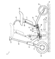
- the folding vehicle 1 of this embodiment includes a front frame 3, a base frame 5, a saddle frame 7, and a pair of rear frames 9.
- a handle 11 is horizontally attached to the upper end of the front frame 3 via a handle stem 13.
- a front wheel 15 is rotatably supported by a lower end portion of the front frame 3 via a front fork 17.
- a base frame 5 is rotatably supported by a rear end portion of the front frame 3 via a first rotation shaft 19.
- a saddle frame 7 and a pair of rear frames 9 are rotatably supported via a second rotation shaft 21.
- the saddle frame 7 is supported by the base frame 5 and the pair of rear frames 9 via the second rotation shaft 21 so as to be rotatable.
- the pair of rear frames 9 are supported so as to be rotatable with respect to the base frame 5 and the saddle frame 7 via the second rotation shaft 21.
- the pair of rear frames 9 are integrated by a connecting arm 23.
- a saddle 25 (see FIG. 2) is attached to the upper end of the saddle frame 7.
- Rear wheels 27 (see FIG. 2) are rotatably supported at the rear ends of the pair of rear frames 9, respectively.
- an operation lever 29 is provided near the lower side of the saddle 25 (see FIG. 2).
- a first lock mechanism 31 that is fixed and released by an operation lever 29 is provided at the lower end of the saddle frame 7. The first lock mechanism 31 will be described later.
- a driving side cam 33 is formed at the lower end of the saddle frame 7 on both the left and right sides with respect to the front direction.
- driven cams 35 are rotatably supported on both the left and right sides with respect to the front direction.
- the driving side cam 33 and the driven side cam 35 constitute a cam mechanism 37.
- the cam mechanism 37 will be described later.
- second lock mechanisms 39 are formed on both the left and right sides with respect to the front direction.
- the second lock mechanism 39 is connected to the driven cam 35 by the link mechanism 41.
- the link mechanism 41 fixes / releases the second lock mechanism 39.
- the second lock mechanism 39 and the link mechanism 41 will be described later.
- the foldable vehicle 1 rotates the saddle 25 toward the handle 11 counterclockwise as viewed in FIG.
- the unfolded state is switched to the folded state.
- the rear end portion of the front frame 3 and the front end portions of the pair of rear frames 9 are connected by a first link portion 43.
- the first link portion 43 operates according to the relative positional relationship between the rear end portion of the front frame 3 and the front end portions of the pair of rear frames 9 when switched from the expanded state to the folded state.
- the operation lever 29 forms a bent link portion and is rotatably supported on the upper end portion of the saddle frame 7 via the first shaft support portion 45.
- a first bent link portion 49 is rotatably supported at the lower end portion of the saddle frame 7 via a second shaft support portion 47.
- the operation lever 29 and the first bent link portion 49 are connected to both ends of the second link portion 55 via the first joint portion 51 and the second joint portion 53, respectively.
- the rear end portion of the third link portion 59 is connected to the lower end portion of the first bent link portion 49 via the third joint portion 57.
- a first roller 61 is provided at the front end of the third link portion 59.
- the first roller 61 is fitted in the bent guide groove 63.
- the bent guide groove 63 is provided at the lower end of the saddle frame 7.
- the first lock mechanism 31 is configured by the third link portion 59, the first roller 61, and the bent guide groove 63.
- the first roller 61 is positioned in a notch portion formed at one end portion (lower side in FIG. 4) of the bent guide groove 63 in the unfolded state.
- the first roller 61 is positioned in the notch portion formed at the other end portion (upper side in FIG. 4) of the bent guide groove 63 in the folded state.
- the saddle frame 7 can be rotated counterclockwise (counterclockwise in the direction of arrow D) as viewed in FIGS.
- the driving side cam 33 is counterclockwise as viewed in FIGS. Rotate around (leftward of arrow E).
- the driving side cam 33 is provided with a notch portion 65 on a side surface facing the driven side cam 35, and a first arcuate guide groove 67 is provided below the notch portion 65.
- a second roller 69 is fitted in the first arcuate guide groove 67.
- the second roller 69 is provided at the rear end portion of the first link portion 43.
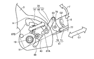
- a rear end portion of the fourth link portion 71 is rotatably supported by the driven side cam 35 via a fourth joint portion 73. Therefore, when the driven cam 35 rotates clockwise in the direction shown in FIGS. 3 and 4 (clockwise in the direction of arrow F), the fourth link portion 71 moves forward in the direction in FIGS. 3 and 4 (leftward in the direction of arrow G1). Move to.
- the lower end portion of the second bent link portion 75 is rotatably supported at the front end portion of the fourth link portion 71 via the fifth joint portion 77.
- the second bent link portion 75 is rotatably supported by the base frame 5 via the third shaft support portion 79.
- the link mechanism 41 is configured by the fourth link portion 71 and the second bent link portion 75.
- the rear end portion of the fifth link portion 81 is rotatably supported on the upper end portion of the second bent link portion 75 via the sixth joint portion 83.
- a third roller 85 is provided at the upper end of the fifth link portion 81.
- the third roller 85 is fitted in the second arcuate guide groove 87.
- the second arcuate guide groove 87 is provided at the lower end of the front frame 3.
- a second lock mechanism 39 is configured by the fifth link portion 81, the third roller 85, and the second arcuate guide groove 87.
- notches 87A and 87B are formed at both ends of the second arcuate guide groove 87.
- the notch part 87A formed in the lower end part of the 2nd circular arc guide groove 87 has the 3rd roller 85 located in the expansion
- the third roller 85 is positioned in the notch portion 87B formed at the upper end portion of the second arcuate guide groove 87 in the folded state.
- a third arcuate guide groove 89 is provided below the second arcuate guide groove 87 at the lower end of the front frame 3.
- a fourth roller 91 is fitted in the third arcuate guide groove 89. The fourth roller 91 is provided at the front end portion of the first link portion 43.
- the operation lever 29 when switching from the unfolded state to the folded state, the operation lever 29 is rotated counterclockwise (counterclockwise in the arrow B1) in FIG. Then, the second link portion 55 moves in the downward direction of the saddle frame 7 (lower left direction of the arrow B2), and the first bent link portion 49 rotates counterclockwise as viewed in FIGS. 3 and 4 (counterclockwise of the arrow B3).
- the third link portion 59 moves in the upper right direction (upper right direction of the arrow C) in FIGS. 3 and 4.
- the first roller 61 moves from one end portion of the bent guide groove 63 (the notch portion on the lower side in FIG. 4) to the center portion, so that the first lock mechanism 31 is released.
- the saddle frame 7 can be rotated counterclockwise (counterclockwise in the direction of arrow D) as viewed in FIGS. Therefore, when the saddle frame 7 is rotated counterclockwise as viewed in FIGS. 3 and 4 (counterclockwise as indicated by arrow D), the driving cam 33 is rotated counterclockwise as viewed in FIGS. 3 and 4 (counterclockwise as indicated by arrow E). ), The driven cam 35 is rotated clockwise in the direction of FIG. 3 and FIG. 4 (clockwise in the direction of arrow F), and the fourth link portion 71 is forward in FIG. 3 and FIG. To the left).
- the second bent link portion 75 rotates clockwise as viewed in FIGS. 3 and 5 (clockwise in the arrow G2), and the fifth link portion 81 moves in the upper right direction (indicated by the arrow H in FIGS. 3 and 5). Move to the upper right) As a result, the third roller 85 comes out of the notch portion 87A of the second arcuate guide groove 87, so that the second lock mechanism 39 is released.
- the saddle 25 is rotated counterclockwise (counterclockwise in the direction of arrow A1) in FIG. 2 toward the handle 11, and the rear wheel 27 is directed toward the front wheel 15.
- the road surface S is moved in the left direction (left direction of the arrow A2).
- the rear frame 9 rotates clockwise as viewed in FIG. 3 (clockwise as indicated by arrow I) and the base frame 5 rotates counterclockwise as viewed in FIGS. 3 and 5 (counterclockwise as indicated by arrow J).
- the second roller 69 moves toward the upper end portion of the first arcuate guide groove 67 and the fourth roller 91 moves toward the lower end portion of the third arcuate guide groove 89.
- the third roller 85 moves along the second arcuate guide groove 87 toward the notch portion 87B.
- the operation lever 29 is rotated clockwise as viewed in FIG. 3 (clockwise in the arrow B1).
- the second link portion 55 moves in the upward direction of the saddle frame 7 (upper right direction of the arrow B2)
- the first bent link portion 49 rotates clockwise as viewed in FIGS. 3 and 4 (clockwise direction of the arrow B3).
- the third link portion 59 moves in the lower left direction (the lower left direction of the arrow C) when viewed in FIGS. 3 and 4.
- the first roller 61 moves from the central portion of the bent guide groove 63 to the other end portion (the notch portion on the upper side in FIG. 4), so that the first lock mechanism 31 is fixed.
- the folding vehicle 1 of the present embodiment shifts from the unfolded state to the folded state, and the folded state is fixed.
- the operation lever 29 when switching from the folded state to the unfolded state, the operation lever 29 is rotated counterclockwise (counterclockwise in the arrow B1) in FIG.
- the saddle 25 is moved away from the handle 11 and rotated clockwise as viewed in FIG. 2 (clockwise in the arrow A1), and the rear wheel 27 is moved away from the front wheel 15 in the right direction as viewed in FIG. 2 (rightward in the arrow A2).
- an operation opposite to the above-described operation is performed.
- a new structure that can be switched between the unfolded state and the folded state has the first lock mechanism 31, the cam mechanism 37, the link mechanism 41, and the second lock mechanism 39. It consists of.
- the cam mechanism 37 can rotate, the link mechanism 41 reciprocates in the front-rear direction according to the rotation direction, and the second lock according to the front-rear direction.
- the mechanism 39 is released or fixed.
- the new structure which is configured by the folding vehicle 1 of the present embodiment and which switches between the unfolded state and the folded state has the first lock mechanism 31 and the second lock mechanism 39, and This is a structure in which the second lock mechanism 39 is released and fixed while interlocking with the link mechanism 41 that is operable via the cam mechanism 37 after being released from the first lock mechanism 31.
- an input operation for releasing the first lock mechanism 31 at the time of switching is performed by the operation lever 29 at a high position in the expanded state or the folded state. It is possible to improve further.
- the saddle frame 7 provided with the saddle 25 at the upper end and the first lock mechanism 31 at the lower end, and the upper end of the saddle frame 7 are provided.
- an operation lever 29 for releasing the lock mechanism 31 is provided.
- the operation lever 29 and the first lock mechanism 31 are separated from each other at both ends of the saddle frame 7, and the operation of the operation lever 29 is within the operating range of the first lock mechanism 31. Since the operation is performed at a remote position, it is possible to improve the safety when the operation lever 29 is operated.
- the cam mechanism 37 is constituted by the driving side cam 33 and the driven side cam 35, and the driving side cam 33 of the cam mechanism 37 is provided at the lower end portion of the saddle frame 7.
- the driven cam 35 of the mechanism 37 is provided at the rear end portion of the base frame 5 and is connected to one end portion of the link mechanism 41, and the second lock mechanism 39 is connected to the other end portion of the link mechanism 41 and the front frame. 3 is provided.
- the operation lever 29 is an example of an “operation unit”.
- this invention is not limited to the said embodiment, A various change is possible in the range which does not deviate from the meaning.
- the grip may appear when the folded state is maintained or when the handle 11 is locked.
- the emerging grip is useful as a convenient part for storing and transporting in a folded state.
Landscapes
- Engineering & Computer Science (AREA)
- Mechanical Engineering (AREA)
- Motorcycle And Bicycle Frame (AREA)
Abstract
本発明は、展開状態と折畳状態との切り替えを行う構造であって、2つのロック機構を有し、ロック機構の一方に対する解除後に動作可能となるリンク機構に連動させながら、ロック機構の他方が解除・固定される構造により、使い勝手をより向上させることが可能な折畳式車両を提供する。折畳式車両(1)は、展開状態と折畳状態との切り替えが可能な構造を、第1ロック機構(31)、カム機構(37)、リンク機構(41)、及び第2ロック機構(39)で構成している。切り替え時に第1ロック機構(31)の解除が行われると、カム機構(37)が回動可能となり、そのカム機構(37)の回動方向に従って、リンク機構(41)が前後方向に往復動し、そのリンク機構(41)の前後方向の往復動に従って、第2ロック機構(39)が解除又は固定される。
Description
本発明は、走行のための展開状態と収納搬送のための折畳状態との切り替えが可能な折畳式車両に関するものである。
従来より、展開状態と折畳状態との切り替えが可能な車両に関する技術が種々提案されている。例えば、下記特許文献1に記載された、折り畳み自転車におけるロック装置では、フロントフレームの後端とメインフレームの前端とに各カム軸をフロントフレーム及びメインフレームとセンタフレームとを結合している各ヒンジピンと平行な軸線回りに回転可能に軸承している。この各カム軸にはそれぞれ各カムが固設されている。
自転車を折り畳むために各ヒンジピン部のロックを解除するには、トグル機構のトグルレバーとトグルリンクのデットポイントを超えた伸張状態からデットポイントが逆側に超えた反転状態に引き動かす。このとき、各カム軸を回転し、各カムは前方ロッドを後退方向に、また、後方ロッドは前進方向に移動可能な状態とし、前方フックはスプリングで、後方フックはスプリングでそれぞれ上方に回転し、ヘッドフレームとフロントフレームとの間と、メインフレームとリヤフォークとの間の各ロックを解除する。
これにより、下記特許文献1に記載のロック装置では、1箇所のトグル機構を操作するワンタッチにより多数個所のロック及びロック解除が得られ、使い勝手が向上すると共に、折り畳み、展開が短時間で迅速に行うことができる利点を有している。
しかしながら、このようにして行われる折り畳みと展開との切り替え構造では、トグル機構が折り畳み自転車の低位置にあることから、トグル機構の操作を、中腰など、身体への負担が大きい姿勢で行わなければならない。従って、使い勝手をより向上させる新たな構造の技術開発が絶えず望まれている。
そこで、本発明は、上述した点を鑑みてなされたものであり、展開状態と折畳状態との切り替えを行う新たな構造であって、2つのロック機構を有し、ロック機構の一方に対する解除後に動作可能となるリンク機構に連動させながらロック機構の他方が解除・固定される構造により、使い勝手をより向上させることが可能な折畳式車両を提供することを課題とする。
この課題を解決するためになされた請求項1に係る発明は、折畳式車両であって、走行のための展開状態と収納搬送のための折畳状態との切り替えが可能な折畳式車両であって、切り替え時に解除が行われる第1ロック機構と、第1ロック機構の解除により回動可能となるカム機構と、カム機構の回動方向に従って往復動するリンク機構と、リンク機構の往復動方向に従って解除又は固定される第2ロック機構とを備えることを特徴とする。
請求項2に係る発明は、請求項1に記載の折畳式車両であって、上端部にサドルが取り付けられると共に下端部に第1ロック機構が設けられるサドルフレームと、サドルフレームの上端部に設けられ、第1ロック機構の解除操作を行うための操作部とを備えることを特徴とする。
請求項3に係る発明は、請求項2に記載の折畳式車両であって、上端部にハンドルが取り付けられると共に下端部に前輪が取り付けられるフロントフレームと、前端部がフロントフレームに軸支され、フロントフレームに対して回動可能とされると共に、後端部がサドルフレームに軸支され、サドルフレームに対して回動可能とされるベースフレームと、後端部に後輪が取り付けられており、前端部がベースフレームに軸支され、ベースフレームに対して回動可能とされるリアフレームとを備え、カム機構を原動側カムと従動側カムで構成し、カム機構の原動側カムがサドルフレームの下端部に設けられ、カム機構の従動側カムがベースフレームの後端部に設けられると共にリンク機構の一端部に連結され、第2ロック機構は、リンク機構の他端部に連結されると共にフロントフレームに設けられることを特徴とする。
請求項4に係る発明は、請求項1乃至請求項3のいずれか一つに記載の折畳式車両であって、ワンタッチにより又はハンドルロック時に出現するグリップを備え、グリップを用いて折畳状態の収納搬送が行われることを特徴とする。
請求項1に係る発明の折畳式車両では、展開状態と折畳状態との切り替えが可能な新たな構造を、第1ロック機構、カム機構、リンク機構、及び第2ロック機構で構成している。その構成では、第1ロック機構の解除が切り替え時に行われると、カム機構が回動可能となり、その回動方向に従ってリンク機構が往復動し、その往復動方向に従って第2ロック機構が解除又は固定される。
従って、請求項1に係る発明の折畳式車両で構成される、展開状態と折畳状態との切り替えを行う新たな構造は、第1ロック機構と第2ロック機構を有しており、第1ロック機構に対する解除後にカム機構を介して動作可能となるリンク機構に連動させながら第2ロック機構が解除・固定される構造である。
また、このような構造では、例えば、切り替え時に第1ロック機構の解除を行わせるための入力動作が、展開状態や折畳状態において高い位置で実行されるようにすれば、使い勝手をより向上させることが可能である。
請求項2に係る発明の折畳式車両では、上端部にサドルが取り付けられると共に下端部に第1ロック機構が設けられるサドルフレームと、サドルフレームの上端部に設けられ、第1ロック機構の解除操作を行うための操作部とを備える。これにより、操作部がサドル付近に設けられるので、第1ロック機構の解除操作を楽な姿勢で行うことができる。
さらに、請求項2に係る発明の折畳式車両では、操作部と第1ロック機構がサドルフレームの両端にあって離れており、操作部の操作が第1ロック機構の作動域とは隔たる位置で行われるので、操作部の操作時における安全性の向上を図ることが可能である。
請求項3に係る発明の折畳式車両では、カム機構を原動側カムと従動側カムで構成し、カム機構の原動側カムがサドルフレームの下端部に設けられ、カム機構の従動側カムがベースフレームの後端部に設けられると共にリンク機構の一端部に連結され、第2ロック機構は、リンク機構の他端部に連結されると共にフロントフレームに設けられる。これにより、操作部の操作が、カム機構、リンク機構、及び第2ロック機構の各作動域とは隔たる位置で行われるので、操作部の操作時における安全性の向上を図ることが可能である。
請求項4に係る発明の折畳式車両では、折畳状態の収納搬送に便利なグリップをワンタッチにより又はハンドルロック時に出現させることが可能である。
[1.折畳式車両の概要]
以下、本発明に係る折畳式車両について、具体化した本実施形態に基づき、図面を参照しつつ説明する。本実施形態の折畳式車両は、フレームを折り畳むことが可能な電動三輪車である。尚、以下の説明に用いる各図面では、基本的構成の一部が省略されて描かれていることがあり、描かれた各部の寸法比等は必ずしも正確ではない。また、ブレーキ関係や電気配線関係等は、省略されて描かれている。
以下、本発明に係る折畳式車両について、具体化した本実施形態に基づき、図面を参照しつつ説明する。本実施形態の折畳式車両は、フレームを折り畳むことが可能な電動三輪車である。尚、以下の説明に用いる各図面では、基本的構成の一部が省略されて描かれていることがあり、描かれた各部の寸法比等は必ずしも正確ではない。また、ブレーキ関係や電気配線関係等は、省略されて描かれている。
図1及び図2に表すように、本実施形態の折畳式車両1は、フロントフレーム3、ベースフレーム5、サドルフレーム7、及び一対のリアフレーム9を備えている。フロントフレーム3の上端部には、ハンドル11がハンドルステム13を介して水平に取り付けられている。フロントフレーム3の下端部には、前輪15がフロントフォーク17を介して回動可能に支持されている。フロントフレーム3の後端部には、ベースフレーム5が第1回動軸19を介して回動可能に支持されている。
ベースフレーム5の後端部には、サドルフレーム7及び一対のリアフレーム9が第2回動軸21を介して回動可能に支持されている。これにより、サドルフレーム7は、第2回動軸21を介して、ベースフレーム5及び一対のリアフレーム9に対して回動可能に支持されている。さらに、一対のリアフレーム9は、第2回動軸21を介して、ベースフレーム5及びサドルフレーム7に対して回動可能に支持されている。
一対のリアフレーム9は、連結アーム23によって一体化されている。
尚、サドルフレーム7の上端部には、サドル25(図2参照)が取り付けられている。一対のリアフレーム9の後端部には、後輪27(図2参照)がそれぞれ回動可能に支持されている。
サドルフレーム7の上端部には、サドル25(図2参照)の下側近傍に操作レバー29が設けられている。サドルフレーム7の下端部には、操作レバー29により固定・解除される第1ロック機構31が設けられている。尚、第1ロック機構31については、後述する。
サドルフレーム7の下端部には、前方向に対する左右の両側において、原動側カム33がそれぞれ形成されている。ベースフレーム5の後端部には、前方向に対する左右の両側において、従動側カム35が回動可能に支持されている。原動側カム33と従動側カム35によって、カム機構37が構成されている。尚、カム機構37については、後述する。
フロントフレーム3の後端部には、前方向に対する左右の両側において、第2ロック機構39がそれぞれ形成されている。第2ロック機構39は、リンク機構41によって、従動側カム35に連結される。リンク機構41は、第2ロック機構39を固定・解除する。尚、第2ロック機構39及びリンク機構41については、後述する。
本実施形態の折畳式車両1は、図2に表すように、サドル25をハンドル11に向けて図2視上反時計回り(矢印A1の左回り)に回動させると共に、後輪27を前輪15に向けて図2視上左方向(矢印A2の左方向)に路面S上を移動させることにより、展開状態から折畳状態に切り替えられる。
尚、フロントフレーム3の後端部と一対のリアフレーム9の前端部は、第1リンク部43によって連結されている。第1リンク部43は、展開状態から折畳状態に切り替えられる際に、フロントフレーム3の後端部と一対のリアフレーム9の前端部の相対的位置関係によって動作する。
[2.展開状態と折畳状態の切り替え時の動作]
本実施形態の折畳式車両1では、展開状態から折畳状態に切り替えられる際に、図3乃至図5に表すように、操作レバー29、第1ロック機構31、カム機構37、第2ロック機構39、及びリンク機構41等が動作する。
本実施形態の折畳式車両1では、展開状態から折畳状態に切り替えられる際に、図3乃至図5に表すように、操作レバー29、第1ロック機構31、カム機構37、第2ロック機構39、及びリンク機構41等が動作する。
図3に表すように、操作レバー29は、屈曲状のリンク部を形成しており、第1軸支部45を介して、サドルフレーム7の上端部に回動可能に支持されている。一方、サドルフレーム7の下端部には、第2軸支部47を介して、第1屈曲状リンク部49が回動可能に支持されている。操作レバー29と第1屈曲状リンク部49は、第1ジョイント部51及び第2ジョイント部53を介して、第2リンク部55の両端にそれぞれ連結されている。
従って、操作レバー29を図3視上反時計回り(矢印B1の左回り)に回動させると、第2リンク部55がサドルフレーム7の下方向(矢印B2の左下方向)に移動し、第1屈曲状リンク部49が図3視上反時計回り(矢印B3の左回り)に回動する。
図4に表すように、第1屈曲状リンク部49の下端部には、第3ジョイント部57を介して、第3リンク部59の後端部が連結されている。第3リンク部59の前端部には、第1ローラー61が設けられている。第1ローラー61は、屈曲状ガイド溝63に嵌め込まれている。屈曲状ガイド溝63は、サドルフレーム7の下端部に設けられている。第3リンク部59、第1ローラー61、及び屈曲状ガイド溝63によって、第1ロック機構31が構成されている。
屈曲状ガイド溝63の両端部には、ノッチ部が形成されている。屈曲状ガイド溝63の一端部(図4視で下方側)に形成されたノッチ部は、展開状態時に第1ローラー61が位置する。屈曲状ガイド溝63の他端部(図4視で上方側)に形成されたノッチ部は、折畳状態時に第1ローラー61が位置する。
そして、第1屈曲状リンク部49が図3視上反時計回り(矢印B3の左回り)に回動すると、第3リンク部59が図4視上右上方向(矢印Cの右上方向)に移動し、第1ローラー61が屈曲状ガイド溝63の中央部に移動する。
従って、展開状態時に操作レバー29を図3視上反時計回り(矢印B1の左回り)に回動させると、第1ローラー61は、屈曲状ガイド溝63の一端部(図4視で下方側のノッチ部)から中央部に移動する。これにより、第1ロック機構31は解除される。
ちなみに、折畳状態時に操作レバー29を図3視上反時計回り(矢印B1の左回り)に回動させると、第1ローラー61は、屈曲状ガイド溝63の他端部(図4視で上方側のノッチ部)から中央部に移動する。これにより、第1ロック機構31は解除される。
第1ロック機構31が解除されると、サドルフレーム7を図3及び図4視上反時計回り(矢印Dの左回り)に回動させることができる。サドルフレーム7が図3及び図4視上反時計回り(矢印Dの左回り)に回動すると、原動側カム33が第2回動軸21を中心にして図3及び図4視上反時計回り(矢印Eの左回り)に回動する。
原動側カム33には、従動側カム35に対向する側面に切欠部65が設けられ、切欠部65の下方に第1円弧状ガイド溝67が設けられている。第1円弧状ガイド溝67には、第2ローラー69が嵌め込まれている。第2ローラー69は、第1リンク部43の後端部に設けられている。
原動側カム33が図3及び図4視上反時計回り(矢印Eの左回り)に回動すると、切欠部65の上方段差部が従動側カム35に突き当たり、従動側カム35が図3及び図4視上時計回り(矢印Fの右回り)に回動する。
従動側カム35には、第4リンク部71の後端部が第4ジョイント部73を介して回動可能に支持されている。従って、従動側カム35が図3及び図4視上時計回り(矢印Fの右回り)に回動すると、第4リンク部71が図3及び図4視上前方向(矢印G1の左方向)に移動する。
図5に表すように、第4リンク部71の前端部には、第2屈曲状リンク部75の下端部が第5ジョイント部77を介して回動可能に支持されている。第2屈曲状リンク部75は、ベースフレーム5に第3軸支部79を介して回動可能に支持されている。第4リンク部71及び第2屈曲状リンク部75によって、リンク機構41が構成されている。
従って、第4リンク部71が図3乃至図5視上前方向(矢印G1の左方向)に移動すると、第2屈曲状リンク部75が図3及び図5視上時計回り(矢印G2の右回り)に回動する。
第2屈曲状リンク部75の上端部には、第5リンク部81の後端部が第6ジョイント部83を介して回動可能に支持されている。第5リンク部81の上端部には、第3ローラー85が設けられている。第3ローラー85は、第2円弧状ガイド溝87に嵌め込まれている。第2円弧状ガイド溝87は、フロントフレーム3の下端部に設けられている。第5リンク部81、第3ローラー85、及び第2円弧状ガイド溝87によって、第2ロック機構39が構成されている。
第2円弧状ガイド溝87の両端部には、ノッチ部87A,87Bが形成されている。第2円弧状ガイド溝87の下端部に形成されたノッチ部87Aは、展開状態時に第3ローラー85が位置する。第2円弧状ガイド溝87の上端部に形成されたノッチ部87Bは、折畳状態時に第3ローラー85が位置する。
そして、第2屈曲状リンク部75が図3及び図5視上時計回り(矢印G2の右回り)に回動すると、第5リンク部81が図3及び図5視上右上方向(矢印Hの右上方向)に移動し、第3ローラー85が第2円弧状ガイド溝87の図3及び図5視上右上方向(矢印Hの右上方向)に移動する。
従って、展開状態時に第4リンク部71が図3乃至図5視上前方向(矢印G1の左方向)に移動すると、第3ローラー85は、第2円弧状ガイド溝87のノッチ部87Aから抜け出る。これにより、第2ロック機構39は解除される。
ちなみに、折畳状態時に第4リンク部71が図3乃至図5視上前方向(矢印G1の左方向)に移動すると、第3ローラー85は、第2円弧状ガイド溝87のノッチ部87Bから抜け出る。これにより、第2ロック機構39は解除される。
尚、フロントフレーム3の下端部には、第2円弧状ガイド溝87の下方に第3円弧状ガイド溝89が設けられている。第3円弧状ガイド溝89には、第4ローラー91が嵌め込まれている。第4ローラー91は、第1リンク部43の前端部に設けられている。
つまり、本実施形態の折畳式車両1において、展開状態から折畳状態に切り替える際は、操作レバー29を図3視上反時計回り(矢印B1の左回り)に回動させる。すると、第2リンク部55がサドルフレーム7の下方向(矢印B2の左下方向)に移動し、第1屈曲状リンク部49が図3及び図4視上反時計回り(矢印B3の左回り)に回動し、第3リンク部59が図3及び図4視上右上方向(矢印Cの右上方向)に移動する。これにより、第1ローラー61は、屈曲状ガイド溝63の一端部(図4視で下方側のノッチ部)から中央部に移動するので、第1ロック機構31は解除される。
第1ロック機構31が解除されると、サドルフレーム7を図3及び図4視上反時計回り(矢印Dの左回り)に回動させることができる。そこで、サドルフレーム7を図3及び図4視上反時計回り(矢印Dの左回り)に回動させると、原動側カム33が図3及び図4視上反時計回り(矢印Eの左回り)に回動し、従動側カム35が図3及び図4視上時計回り(矢印Fの右回り)に回動し、第4リンク部71が図3及び図4視上前方向(矢印G1の左方向)に移動する。
さらに、第2屈曲状リンク部75が図3及び図5視上時計回り(矢印G2の右回り)に回動し、第5リンク部81が図3及び図5視上右上方向(矢印Hの右上方向)に移動する。これにより、第3ローラー85は、第2円弧状ガイド溝87のノッチ部87Aから抜け出るので、第2ロック機構39は解除される。
第2ロック機構39が解除された後、サドル25をハンドル11に向けて図2視上反時計回り(矢印A1の左回り)に回動させる共に、後輪27を前輪15に向けて図2視上左方向(矢印A2の左方向)に路面S上を移動させる。すると、リアフレーム9が図3視上時計回り(矢印Iの右回り)に回動すると共にベースフレーム5が図3及び図5視上反時計回り(矢印Jの左回り)に回動するので、第2ローラー69が第1円弧状ガイド溝67の上端部に向かって移動する共に、第4ローラー91が第3円弧状ガイド溝89の下端部に向かって移動する。
これにより、第3ローラー85は、第2円弧状ガイド溝87に沿ってノッチ部87B側に向かって移動する。
同時に、第2ローラー69が第1円弧状ガイド溝67の上端部に向かって移動して、原動側カム33が図3及び図4視上時計回り(矢印Eの右回り)に回動するので、切欠部65の下方段差部が従動側カム35に突き当たり、従動側カム35が図3及び図4視上反時計回り(矢印Fの左回り)に回動する。
さらに、第4リンク部71が図3及び図4視上後方向(矢印G1の右方向)に移動するので、第2屈曲状リンク部75が図3及び図5視上反時計回り(矢印G2の左回り)に回動し、第5リンク部81が図3及び図5視上左下方向(矢印Hの左下方向)に移動する。これにより、第3ローラー85は、第2円弧状ガイド溝87のノッチ部87Bに位置するので、第2ロック機構39が固定される。
その後、操作レバー29を図3視上時計回り(矢印B1の右回り)に回動させる。すると、第2リンク部55がサドルフレーム7の上方向(矢印B2の右上方向)に移動し、第1屈曲状リンク部49が図3及び図4視上時計回り(矢印B3の右回り)に回動し、第3リンク部59が図3及び図4視上左下方向(矢印Cの左下方向)に移動する。このとき、第1ローラー61は、屈曲状ガイド溝63の中央部から他端部(図4視で上方側のノッチ部)に移動するので、第1ロック機構31が固定される。
このようにして、本実施形態の折畳式車両1は、展開状態から折畳状態に移行し、折畳状態が固定される。
一方、本実施形態の折畳式車両1において、折畳状態から展開状態に切り替える際は、操作レバー29を図3視上反時計回り(矢印B1の左回り)に回動させた後で、サドル25をハンドル11から遠ざけて図2視上時計回り(矢印A1の右回り)に回動させると共に、後輪27を前輪15から遠ざけて図2視上右方向(矢印A2の右方向)に路面S上を移動させる。このとき、上述した動作とは反対の動作が行われる。
[3.まとめ]
すなわち、本実施形態の折畳式車両1では、展開状態と折畳状態との切り替えが可能な新たな構造を、第1ロック機構31、カム機構37、リンク機構41、及び第2ロック機構39で構成している。その構成では、第1ロック機構31の解除が切り替え時に行われると、カム機構37が回動可能となり、その回動方向に従ってリンク機構41が前後方向の往復動し、その前後方向に従って第2ロック機構39が解除又は固定される。
すなわち、本実施形態の折畳式車両1では、展開状態と折畳状態との切り替えが可能な新たな構造を、第1ロック機構31、カム機構37、リンク機構41、及び第2ロック機構39で構成している。その構成では、第1ロック機構31の解除が切り替え時に行われると、カム機構37が回動可能となり、その回動方向に従ってリンク機構41が前後方向の往復動し、その前後方向に従って第2ロック機構39が解除又は固定される。
従って、本実施形態の折畳式車両1で構成される、展開状態と折畳状態との切り替えを行う新たな構造は、第1ロック機構31と第2ロック機構39を有しており、第1ロック機構31に対する解除後にカム機構37を介して動作可能となるリンク機構41に連動させながら第2ロック機構39が解除・固定される構造である。
また、このような構造では、例えば、切り替え時に第1ロック機構31の解除を行わせるための入力動作が、展開状態や折畳状態において高い位置にある操作レバー29で実行されており、使い勝手をより向上させることが可能である。
また、本実施形態の折畳式車両1では、上端部にサドル25が取り付けられると共に下端部に第1ロック機構31が設けられるサドルフレーム7と、サドルフレーム7の上端部に設けられ、第1ロック機構31の解除操作を行うための操作レバー29とを備える。これにより、操作レバー29がサドル25付近に設けられているので、第1ロック機構31の解除操作を楽な姿勢で行うことができる。
さらに、本実施形態の折畳式車両1では、操作レバー29と第1ロック機構31がサドルフレーム7の両端にあって離れており、操作レバー29の操作が第1ロック機構31の作動域とは隔たる位置で行われるので、操作レバー29の操作時における安全性の向上を図ることが可能である。
また、本実施形態の折畳式車両1では、カム機構37を原動側カム33と従動側カム35で構成し、カム機構37の原動側カム33がサドルフレーム7の下端部に設けられ、カム機構37の従動側カム35がベースフレーム5の後端部に設けられると共にリンク機構41の一端部に連結され、第2ロック機構39は、リンク機構41の他端部に連結されると共にフロントフレーム3に設けられる。これにより、操作レバー29の操作が、カム機構37、リンク機構41、及び第2ロック機構39の各作動域とは隔たる位置で行われるので、操作レバー29の操作時における安全性の向上を図ることが可能である。
ちなみに、本実施形態において、操作レバー29は「操作部」の一例である。
[4.その他]
尚、本発明は上記実施形態に限定されるものでなく、その趣旨を逸脱しない範囲で様々な変更が可能である。
例えば、本実施形態の折畳式車両1では、折畳状態が保持されているとき又はハンドル11がロックされているときにグリップを出現させてもよい。出現したグリップは、折畳状態の収納搬送するときに便利な部品として役立つ。
尚、本発明は上記実施形態に限定されるものでなく、その趣旨を逸脱しない範囲で様々な変更が可能である。
例えば、本実施形態の折畳式車両1では、折畳状態が保持されているとき又はハンドル11がロックされているときにグリップを出現させてもよい。出現したグリップは、折畳状態の収納搬送するときに便利な部品として役立つ。
1 折畳式車両
3 フロントフレーム
5 ベースフレーム
7 サドルフレーム
9 リアフレーム
11 ハンドル
25 サドル
27 後輪
29 操作レバー
31 第1ロック機構
33 原動側カム
35 従動側カム
37 カム機構
39 第2ロック機構
41 リンク機構
3 フロントフレーム
5 ベースフレーム
7 サドルフレーム
9 リアフレーム
11 ハンドル
25 サドル
27 後輪
29 操作レバー
31 第1ロック機構
33 原動側カム
35 従動側カム
37 カム機構
39 第2ロック機構
41 リンク機構
Claims (4)
- 走行のための展開状態と収納搬送のための折畳状態との切り替えが可能な折畳式車両であって、
前記切り替え時に解除が行われる第1ロック機構と、
前記第1ロック機構の解除により回動可能となるカム機構と、
前記カム機構の回動方向に従って往復動するリンク機構と、
前記リンク機構の往復動方向に従って解除又は固定される第2ロック機構とを備えることを特徴とする折畳式車両。 - 上端部にサドルが取り付けられると共に下端部に前記第1ロック機構が設けられるサドルフレームと、
前記サドルフレームの上端部に設けられ、前記第1ロック機構の解除操作を行うための操作部とを備えることを特徴とする請求項1に記載の折畳式車両。 - 上端部にハンドルが取り付けられると共に下端部に前輪が取り付けられるフロントフレームと、
前端部が前記フロントフレームに軸支され、前記フロントフレームに対して回動可能とされると共に、後端部が前記サドルフレームに軸支され、前記サドルフレームに対して回動可能とされるベースフレームと、
後端部に後輪が取り付けられており、前端部が前記ベースフレームに軸支され、前記ベースフレームに対して回動可能とされるリアフレームとを備え、
前記カム機構を原動側カムと従動側カムで構成し、
前記カム機構の前記原動側カムが前記サドルフレームの下端部に設けられ、
前記カム機構の前記従動側カムが前記ベースフレームの後端部に設けられると共に前記リンク機構の一端部に連結され、
前記第2ロック機構は、前記リンク機構の他端部に連結されると共に前記フロントフレームに設けられることを特徴とする請求項2に記載の折畳式車両。 - ワンタッチにより又はハンドルロック時に出現するグリップを備え、前記グリップを用いて前記折畳状態の収納搬送が行われることを特徴とする請求項1乃至請求項3のいずれか一つに記載の折畳式車両。
Applications Claiming Priority (2)
| Application Number | Priority Date | Filing Date | Title |
|---|---|---|---|
| JP2015240211A JP6514096B2 (ja) | 2015-12-09 | 2015-12-09 | 折畳式車両 |
| JP2015-240211 | 2015-12-09 |
Publications (1)
| Publication Number | Publication Date |
|---|---|
| WO2017098766A1 true WO2017098766A1 (ja) | 2017-06-15 |
Family
ID=59012944
Family Applications (1)
| Application Number | Title | Priority Date | Filing Date |
|---|---|---|---|
| PCT/JP2016/076742 Ceased WO2017098766A1 (ja) | 2015-12-09 | 2016-09-12 | 折畳式車両 |
Country Status (2)
| Country | Link |
|---|---|
| JP (1) | JP6514096B2 (ja) |
| WO (1) | WO2017098766A1 (ja) |
Cited By (1)
| Publication number | Priority date | Publication date | Assignee | Title |
|---|---|---|---|---|
| JP2022053807A (ja) * | 2020-09-25 | 2022-04-06 | 本田技研工業株式会社 | 車両 |
Families Citing this family (5)
| Publication number | Priority date | Publication date | Assignee | Title |
|---|---|---|---|---|
| JP7212679B2 (ja) * | 2017-09-27 | 2023-01-25 | ラジオ・フライヤー・インコーポレイテッド | 折り畳み式三輪車 |
| JP2025081141A (ja) * | 2023-11-15 | 2025-05-27 | 株式会社Gear | 電動カート |
| JP2025154785A (ja) * | 2024-03-29 | 2025-10-10 | 株式会社アイシン | 折り畳み装置 |
| JP2025154496A (ja) * | 2024-03-29 | 2025-10-10 | 株式会社アイシン | 折り畳み装置 |
| JP2025154652A (ja) * | 2024-03-29 | 2025-10-10 | 株式会社アイシン | 折り畳み装置 |
Citations (10)
| Publication number | Priority date | Publication date | Assignee | Title |
|---|---|---|---|---|
| JPH0554184U (ja) * | 1991-12-24 | 1993-07-20 | 丸石自転車株式会社 | 折り畳み式自転車 |
| JPH07196062A (ja) * | 1993-12-28 | 1995-08-01 | Sekinemasahiko Shoten:Kk | 折り畳み式二輪車 |
| JPH10291488A (ja) * | 1997-04-21 | 1998-11-04 | Kanto Auto Works Ltd | 折り畳み自転車におけるロック装置 |
| WO2004028890A1 (ja) * | 2002-09-25 | 2004-04-08 | Kouji Kobayashi | 折り畳み自転車 |
| JP2006082777A (ja) * | 2004-09-17 | 2006-03-30 | Aidesu Kk | 折畳み三輪車 |
| JP2006327237A (ja) * | 2005-05-23 | 2006-12-07 | Kazutaka Kitahara | 自転車用フレーム |
| JP2012166706A (ja) * | 2011-02-15 | 2012-09-06 | Hisanori Nanba | 折り畳み自転車 |
| JP2013043469A (ja) * | 2011-08-22 | 2013-03-04 | Denso Corp | 折りたたみ可能な乗り物 |
| JP2014088076A (ja) * | 2012-10-29 | 2014-05-15 | Aidesu Kk | 折畳み三輪車 |
| WO2016093002A1 (ja) * | 2014-12-10 | 2016-06-16 | 豊田鉄工株式会社 | 折り畳み式車両 |
-
2015
- 2015-12-09 JP JP2015240211A patent/JP6514096B2/ja active Active
-
2016
- 2016-09-12 WO PCT/JP2016/076742 patent/WO2017098766A1/ja not_active Ceased
Patent Citations (10)
| Publication number | Priority date | Publication date | Assignee | Title |
|---|---|---|---|---|
| JPH0554184U (ja) * | 1991-12-24 | 1993-07-20 | 丸石自転車株式会社 | 折り畳み式自転車 |
| JPH07196062A (ja) * | 1993-12-28 | 1995-08-01 | Sekinemasahiko Shoten:Kk | 折り畳み式二輪車 |
| JPH10291488A (ja) * | 1997-04-21 | 1998-11-04 | Kanto Auto Works Ltd | 折り畳み自転車におけるロック装置 |
| WO2004028890A1 (ja) * | 2002-09-25 | 2004-04-08 | Kouji Kobayashi | 折り畳み自転車 |
| JP2006082777A (ja) * | 2004-09-17 | 2006-03-30 | Aidesu Kk | 折畳み三輪車 |
| JP2006327237A (ja) * | 2005-05-23 | 2006-12-07 | Kazutaka Kitahara | 自転車用フレーム |
| JP2012166706A (ja) * | 2011-02-15 | 2012-09-06 | Hisanori Nanba | 折り畳み自転車 |
| JP2013043469A (ja) * | 2011-08-22 | 2013-03-04 | Denso Corp | 折りたたみ可能な乗り物 |
| JP2014088076A (ja) * | 2012-10-29 | 2014-05-15 | Aidesu Kk | 折畳み三輪車 |
| WO2016093002A1 (ja) * | 2014-12-10 | 2016-06-16 | 豊田鉄工株式会社 | 折り畳み式車両 |
Cited By (2)
| Publication number | Priority date | Publication date | Assignee | Title |
|---|---|---|---|---|
| JP2022053807A (ja) * | 2020-09-25 | 2022-04-06 | 本田技研工業株式会社 | 車両 |
| JP7399056B2 (ja) | 2020-09-25 | 2023-12-15 | 本田技研工業株式会社 | 車両 |
Also Published As
| Publication number | Publication date |
|---|---|
| JP2017105303A (ja) | 2017-06-15 |
| JP6514096B2 (ja) | 2019-05-15 |
Similar Documents
| Publication | Publication Date | Title |
|---|---|---|
| WO2017098766A1 (ja) | 折畳式車両 | |
| JP4994925B2 (ja) | ベビーカー | |
| JP6510240B2 (ja) | 折畳式車両 | |
| TWI429549B (zh) | 嬰兒車(二) | |
| JP5436911B2 (ja) | ベビーカー | |
| JP5944141B2 (ja) | ベビーカー | |
| JP6195136B2 (ja) | 折りたたみ二輪車 | |
| JP6209100B2 (ja) | 折畳式乳母車 | |
| JP5913546B2 (ja) | ベビーカー | |
| JP2010253976A (ja) | 折畳式手押し車 | |
| JP5766772B2 (ja) | ベビーカー | |
| JP5101744B2 (ja) | ベビーカー | |
| CN101605688A (zh) | 婴儿车 | |
| JP2012136222A (ja) | ベビーカー | |
| JP6400939B2 (ja) | 乳母車 | |
| JP6546103B2 (ja) | 折畳車両 | |
| JP4549712B2 (ja) | ベビーカーのハンドルロック連動装置 | |
| JP5904464B2 (ja) | 折り畳み二輪車用フレーム及び二輪車 | |
| JP5898996B2 (ja) | 折り畳み二輪車用フレーム及び二輪車 | |
| JP2014065416A (ja) | 手押し車のロック機構 | |
| JP2017124641A (ja) | 複輪車両 | |
| HK1185044A (en) | Baby buggy | |
| HK1185044B (en) | Baby buggy |
Legal Events
| Date | Code | Title | Description |
|---|---|---|---|
| 121 | Ep: the epo has been informed by wipo that ep was designated in this application |
Ref document number: 16872666 Country of ref document: EP Kind code of ref document: A1 |
|
| NENP | Non-entry into the national phase |
Ref country code: DE |
|
| 122 | Ep: pct application non-entry in european phase |
Ref document number: 16872666 Country of ref document: EP Kind code of ref document: A1 |