WO2017094675A1 - 耐遅れ破壊性および疲労特性に優れた高強度ボルト、およびその製造方法 - Google Patents
耐遅れ破壊性および疲労特性に優れた高強度ボルト、およびその製造方法 Download PDFInfo
- Publication number
- WO2017094675A1 WO2017094675A1 PCT/JP2016/085217 JP2016085217W WO2017094675A1 WO 2017094675 A1 WO2017094675 A1 WO 2017094675A1 JP 2016085217 W JP2016085217 W JP 2016085217W WO 2017094675 A1 WO2017094675 A1 WO 2017094675A1
- Authority
- WO
- WIPO (PCT)
- Prior art keywords
- bolt
- less
- amount
- delayed fracture
- fracture resistance
- Prior art date
- Legal status (The legal status is an assumption and is not a legal conclusion. Google has not performed a legal analysis and makes no representation as to the accuracy of the status listed.)
- Ceased
Links
Classifications
-
- C—CHEMISTRY; METALLURGY
- C21—METALLURGY OF IRON
- C21D—MODIFYING THE PHYSICAL STRUCTURE OF FERROUS METALS; GENERAL DEVICES FOR HEAT TREATMENT OF FERROUS OR NON-FERROUS METALS OR ALLOYS; MAKING METAL MALLEABLE, e.g. BY DECARBURISATION OR TEMPERING
- C21D7/00—Modifying the physical properties of iron or steel by deformation
- C21D7/02—Modifying the physical properties of iron or steel by deformation by cold working
- C21D7/04—Modifying the physical properties of iron or steel by deformation by cold working of the surface
- C21D7/06—Modifying the physical properties of iron or steel by deformation by cold working of the surface by shot-peening or the like
-
- C—CHEMISTRY; METALLURGY
- C21—METALLURGY OF IRON
- C21D—MODIFYING THE PHYSICAL STRUCTURE OF FERROUS METALS; GENERAL DEVICES FOR HEAT TREATMENT OF FERROUS OR NON-FERROUS METALS OR ALLOYS; MAKING METAL MALLEABLE, e.g. BY DECARBURISATION OR TEMPERING
- C21D9/00—Heat treatment, e.g. annealing, hardening, quenching or tempering, adapted for particular articles; Furnaces therefor
-
- C—CHEMISTRY; METALLURGY
- C22—METALLURGY; FERROUS OR NON-FERROUS ALLOYS; TREATMENT OF ALLOYS OR NON-FERROUS METALS
- C22C—ALLOYS
- C22C38/00—Ferrous alloys, e.g. steel alloys
-
- C—CHEMISTRY; METALLURGY
- C22—METALLURGY; FERROUS OR NON-FERROUS ALLOYS; TREATMENT OF ALLOYS OR NON-FERROUS METALS
- C22C—ALLOYS
- C22C38/00—Ferrous alloys, e.g. steel alloys
- C22C38/18—Ferrous alloys, e.g. steel alloys containing chromium
- C22C38/34—Ferrous alloys, e.g. steel alloys containing chromium with more than 1.5% by weight of silicon
-
- C—CHEMISTRY; METALLURGY
- C22—METALLURGY; FERROUS OR NON-FERROUS ALLOYS; TREATMENT OF ALLOYS OR NON-FERROUS METALS
- C22C—ALLOYS
- C22C38/00—Ferrous alloys, e.g. steel alloys
- C22C38/18—Ferrous alloys, e.g. steel alloys containing chromium
- C22C38/40—Ferrous alloys, e.g. steel alloys containing chromium with nickel
- C22C38/50—Ferrous alloys, e.g. steel alloys containing chromium with nickel with titanium or zirconium
-
- Y—GENERAL TAGGING OF NEW TECHNOLOGICAL DEVELOPMENTS; GENERAL TAGGING OF CROSS-SECTIONAL TECHNOLOGIES SPANNING OVER SEVERAL SECTIONS OF THE IPC; TECHNICAL SUBJECTS COVERED BY FORMER USPC CROSS-REFERENCE ART COLLECTIONS [XRACs] AND DIGESTS
- Y02—TECHNOLOGIES OR APPLICATIONS FOR MITIGATION OR ADAPTATION AGAINST CLIMATE CHANGE
- Y02P—CLIMATE CHANGE MITIGATION TECHNOLOGIES IN THE PRODUCTION OR PROCESSING OF GOODS
- Y02P10/00—Technologies related to metal processing
- Y02P10/20—Recycling
Definitions
- This disclosure relates to bolts used in automobiles and various industrial machines. Specifically, the present invention relates to a technique for improving delayed fracture resistance and fatigue characteristics of a high-strength bolt having a tensile strength of 1500 MPa or more.
- Delayed fracture is a fracture that occurs after a certain time has elapsed since the stress was applied to the steel material. About this cause, since it is thought that various factors are intertwined intricately, it is difficult to specify the cause. That is, as factors that influence the delayed fracture phenomenon, the effects of tempering temperature, structure, material hardness, crystal grain size, various alloy elements, etc. have been recognized. However, the means for preventing delayed destruction has not been established, and the fact is that various methods have only been proposed by trial and error. However, in general, there is a common recognition that hydrogen embrittlement is involved.
- Patent Documents 1 and 2 have been proposed as techniques for improving delayed fracture resistance.
- Patent Document 1 discloses a high-strength bolt having a tensile strength of 1400 MPa or more, a compressive residual stress of 20 to 95% of the tensile strength, and a 10-point average roughness of the surface controlled to 10 ⁇ m or less. Proposed.
- As a method of applying the compressive residual stress a method of focusing and irradiating a pulse laser beam on the bolt surface is described.
- Patent Document 2 contains the maximum value of the compressive residual stress within 200 ⁇ m from the surface of the steel material with a tensile strength of 125 kgf / mm 2 or more after containing 0.2 to 1.2% of Mo as the component composition ( High strength steels for mechanical structures have been proposed in which ⁇ r) satisfies ⁇ r / ⁇ B ⁇ 0.6 with respect to the tensile strength ( ⁇ B) of the material. As a method for applying the compressive residual stress, shot peening is described.
- Mo is 0.2 to 1.2% in order to obtain hardenability of steel, have temper softening resistance, and obtain a tensile strength of 125 kgf / mm 2 or more at a tempering temperature of 400 ° C. or higher. Contains. However, adding 0.2% or more of Mo to a steel type containing 1.5 to 3.0% of Si in order to increase the strength may significantly reduce hot ductility, making it difficult to industrially mass-produce. May be.
- Delayed fracture generally tends to occur as the amount of C increases.
- the surface layer of a bolt is intentionally decarburized.
- the hardness of the surface layer is reduced, so that the fatigue characteristics are deteriorated. Therefore, it is difficult to achieve both delayed fracture resistance and fatigue characteristics at a high level.
- the present disclosure has been made in view of the above circumstances, and its purpose is to secure a tensile strength of 1500 MPa or more and to provide a high-strength bolt excellent in delayed fracture resistance and fatigue characteristics, and a method for manufacturing the same. It is to provide.
- the high-strength bolt according to the present disclosure that has solved the above-mentioned problems is that the composition of the base material is, by mass%, C: 0.25 to 0.5%, Si: 1.5 to 3.0% , Mn: 0.1 to 1.5%, P: more than 0% to 0.03% or less, S: more than 0% to 0.03% or less, Cr: 0.05 to 1.5%, Mo: 0% or more Less than 0.2%, Al: 0.01 to 0.1%, and N: 0.002 to 0.020%, Ti: 0.02 to 0.1%, and Nb: 0.0. It is a bolt containing 02 to 0.1% of one or two, the balance being iron and inevitable impurities.
- the bolt has a tensile strength of 1500 MPa or more, a compressive residual stress at a depth of 0.05 mm from the screw bottom surface of the bolt is tensile strength ⁇ 0.15 MPa or more, and the diameter of the bolt shaft is D.
- the gist is that the average grain size of the prior austenite crystal grains at the D / 4 position is 5 to 15 ⁇ m.
- the bolt may further contain other elements by mass% so as to satisfy at least the following (a) or (b).
- the ratio of the C amount at a depth of 0.05 mm from the screw bottom surface of the bolt is preferably 50 to 110% with respect to the C amount of the base material.
- the high-strength bolt according to the present disclosure can be manufactured by applying compressive residual stress by performing at least one selected from rolling and shot peening after quenching and tempering.
- the quenching is preferably performed in an atmosphere having a carbon potential of 50 to 110% with respect to the C content of the base material.
- annealing may be further performed.
- the component composition of the bolt, the compressive residual stress at a depth of 0.05 mm from the thread bottom surface of the bolt, and the average grain size of the prior austenite grains at the D / 4 position with respect to the diameter D at the bolt shaft Since the tensile strength of 1500 MPa or more is secured, a high-strength bolt that achieves both delayed fracture resistance and fatigue characteristics at a high level can be provided. Moreover, according to this indication, the manufacturing method of the said high intensity
- the component composition of the bolt in particular, the Si content is as high as 1.5 to 3.0%, the Mo content is controlled as low as less than 0.2%, and the depth from the screw bottom surface of the bolt is 0.05 mm
- High-strength bolts with a tensile strength of 1500 MPa or more with excellent delayed fracture resistance and fatigue properties by appropriately controlling the compressive residual stress and the average grain size of the prior austenite grains at the D / 4 position in the bolt shaft The present disclosure has been completed.
- the bolt according to the embodiment of the present invention includes, as basic components, C: 0.25 to 0.5%, Si: 1.5 to 3.0%, Mn: 0.1 to 1.5%, P: 0 %: 0.0% to 0.03%, S: more than 0% to 0.03%, Cr: 0.05 to 1.5%, Mo: 0% to less than 0.2%, Al: 0.01 to 0.1 %, And N: 0.002 to 0.020%, and further, Ti: 0.02 to 0.1% and Nb: 0.02 to 0.1%, or one or two of them .
- % in the component composition means mass%.
- C is an element necessary for securing the strength of the bolt, and in order to make the tensile strength 1500 MPa or more, the C amount is 0.25% or more.
- the amount of C is preferably 0.30% or more, more preferably 0.33% or more. However, if C is contained excessively, delayed fracture resistance and fatigue characteristics deteriorate, so the C content is 0.5% or less.
- the amount of C is preferably 0.45% or less, more preferably 0.43% or less.
- Si is an element required to act as a deoxidizer and to ensure the strength of the bolt.
- Si is an element that suppresses the precipitation of coarse cementite and contributes to the improvement of delayed fracture resistance. Further, by containing Si, a high compressive residual stress can be imparted to the surface layer of the bolt by a rolling process after quenching and tempering, shot peening of the rolling process, etc., so that delayed fracture resistance and fatigue characteristics can be improved.
- the Si amount is set to 1.5% or more.
- the amount of Si is preferably 1.6% or more, more preferably 1.7% or more.
- the Si amount is 3.0% or less.
- the amount of Si is preferably 2.5% or less, more preferably 2.0% or less.
- Mn is an element that increases the strength of the bolt and suppresses the formation of FeS that deteriorates delayed fracture resistance by forming a compound with S.
- the amount of Mn is made 0.1% or more.
- the amount of Mn is preferably 0.13% or more, more preferably 0.15% or more.
- the amount of Mn is 1.5% or less.
- the amount of Mn is preferably 1.3% or less, more preferably 1.1% or less.
- the P amount is 0.03% or less.
- the amount of P is preferably 0.015% or less, more preferably 0.010% or less.
- the amount of P is preferably as small as possible, but it is difficult to make it 0%, and usually about 0.003% is contained.
- the S amount is 0.03% or less.
- the amount of S is preferably 0.015% or less, more preferably 0.010% or less.
- the amount of S is preferably as small as possible, but it is difficult to make it 0%, and usually about 0.003% is contained.
- the Cr amount is an element necessary for improving the corrosion resistance of bolts and improving delayed fracture resistance.
- the Cr amount is set to 0.05% or more.
- the amount of Cr is preferably 0.10% or more, more preferably 0.20% or more.
- the Cr content is 1.5% or less.
- the amount of Cr is preferably 1.3% or less, more preferably 1.1% or less.
- Mo is an element that finely precipitates during tempering to increase the tough ductility of the steel and improve delayed fracture resistance and fatigue characteristics of the bolt.
- the Mo amount is set to 0% or more.
- the amount of Mo is preferably 0.001% or more, more preferably 0.004% or more, and still more preferably 0.01% or more.
- Mo is contained in an amount of 0.2% or more in the component composition defined in the embodiment of the present invention, the hot ductility is lowered and the production becomes impossible. Further, since Mo is an expensive element, excessive addition increases the cost. Therefore, in the embodiment of the present invention, the Mo amount is less than 0.2%.
- the amount of Mo is preferably 0.15% or less, more preferably 0.10% or less.
- Al is an element that acts as a deoxidizer and forms nitrides to prevent coarsening of the prior austenite grains due to the pinning effect, improving the toughness of steel, delay fracture resistance and fatigue properties. Can improve.
- the Al content is set to 0.01% or more.
- the amount of Al is preferably 0.015% or more, more preferably 0.020% or more. However, if Al is contained excessively, coarse nitrides are formed and the fatigue characteristics are deteriorated. Therefore, in the embodiment of the present invention, the Al amount is 0.1% or less.
- the amount of Al is preferably 0.08% or less, more preferably 0.06% or less.
- N is an element that forms a nitride by combining with Al, Ti, Nb or the like, and prevents the coarsening of the prior austenite crystal grains due to the pinning effect, and improves the toughness of the steel, delayed fracture resistance and The fatigue characteristics can be improved.
- the N content is set to 0.002% or more.
- the N amount is preferably 0.003% or more, more preferably 0.0035% or more.
- the N amount is 0.02% or less.
- the N amount is preferably 0.01% or less, more preferably 0.008% or less.
- Ti and Nb are elements that form carbonitrides with C and N and prevent the coarsening of the prior austenite grains due to the pinning effect, and improve the toughness of the steel, resulting in delayed fracture resistance and fatigue properties. improves. Ti and Nb may be used alone or in combination.
- the Ti amount is 0.02% or more, preferably 0.03% or more, more preferably 0.05% or more.
- the Nb content is 0.02% or more, preferably 0.03% or more, more preferably 0.05% or more.
- the Ti amount is 0.1% or less, preferably 0.08% or less, more preferably 0.06% or less.
- the Nb content is 0.1% or less, preferably 0.08% or less, more preferably 0.06% or less.
- the basic components of the bolt according to the embodiment of the present invention are as described above, and the balance is substantially iron.
- the bolt according to the embodiment of the present invention may further include other elements as necessary.
- B) one or two of V: more than 0% and 0.5% or less, and W: more than 0% and 0.5% or less, Etc. may be contained.
- Cu and Ni are elements that act to improve the corrosion resistance of steel and the delayed fracture resistance of bolts. Cu and Ni may be used alone or in combination.
- Cu is preferably 0.05% or more, more preferably 0.10% or more, and still more preferably 0.13% or more.
- the amount of Cu is preferably 0.5% or less, more preferably 0.4% or less, and still more preferably 0.35% or less.
- Ni is preferably 0.05% or more, more preferably 0.10% or more, and further preferably 0.15% or more. However, even if Ni is contained excessively, the above-described effect is saturated and the cost is increased. Therefore, in the embodiment of the present invention, the amount of Ni is preferably 1% or less, more preferably 0.8% or less, and still more preferably 0.7% or less.
- V and W are elements that form carbonitrides and prevent coarsening of the prior austenite crystal grains by a pinning effect, and act to improve delayed fracture resistance and fatigue characteristics. V and W may be used alone or in combination.
- V is preferably 0.01% or more, more preferably 0.03% or more, and still more preferably 0.05% or more.
- the V amount is preferably 0.5% or less, more preferably 0.3% or less, and still more preferably 0.2% or less.
- W is preferably 0.01% or more, more preferably 0.05% or more, and still more preferably 0.1% or more.
- the W amount is preferably 0.5% or less, more preferably 0.3% or less, and still more preferably 0.2% or less.
- the bolt according to the embodiment of the present invention is premised on a tensile strength of 1500 MPa or more.
- the tensile strength is preferably 1600 MPa or more, more preferably 1700 MPa or more.
- the upper limit of tensile strength is not specifically limited, For example, it is about 2200 MPa.
- the compressive residual stress at a depth of 0.05 mm from the screw bottom surface of the bolt has a tensile strength of 0.15 MPa or more, and the diameter at the shaft portion of the bolt is D ( mm), it is important that the average grain size of the prior austenite crystal grains at the D / 4 position is 5 to 15 ⁇ m.
- the compressive residual stress at a position of a depth of 0.05 mm from the screw bottom surface of the bolt is controlled. Specifically, the compressive residual stress at a depth of 0.05 mm from the screw bottom surface is tensile strength ⁇ 0.15 MPa or more.
- the delayed fracture resistance and fatigue characteristics can be improved by applying a compressive residual stress of tensile strength x 0.15 MPa or more to the 0.05 mm depth position.
- the compressive residual stress is preferably tensile strength ⁇ 0.25 MPa or more, more preferably tensile strength ⁇ 0.30 MPa or more.
- the compressive residual stress at the depth of 0.05 mm is preferably as high as possible, but never higher than the tensile strength of the bolt.
- the compressive residual stress is approximately tensile strength ⁇ 0.90 MPa or less.
- the compressive residual stress at the depth of 0.05 mm can be measured by the X-ray residual stress measurement method.
- the average grain size of the prior austenite crystal grains at the D / 4 position is 15 ⁇ m or less.
- the average particle diameter is preferably 10 ⁇ m or less, more preferably 8 ⁇ m or less.
- the ratio of the C amount (mass%) at a position of 0.05 mm in depth from the screw bottom surface of the bolt is more than the C amount (mass%) in the base material of the bolt. It is preferably 50 to 110%.
- the ratio of the C amount (mass%) at a depth of 0.05 mm from the screw bottom surface of the bolt is preferably 60% or more, more preferably 65% or more with respect to the C amount (mass%) of the base material. It is.
- the ratio of the C amount (mass%) at a depth of 0.05 mm from the screw bottom surface of the bolt is preferably 100% or less, more preferably 95% or less with respect to the C amount (mass%) of the base material. It is.
- the average grain size of the prior austenite crystal grains at a depth of 0.05 mm from the screw bottom surface of the bolt is 0.01 to 5 ⁇ m.
- the average particle diameter is more preferably 3 ⁇ m or less, still more preferably 2 ⁇ m or less.
- the prior austenite crystal grains at a depth of 0.05 mm from the screw bottom surface of the bolt are preferably as small as possible.
- the average grain size is approximately 0. It is 01 ⁇ m or more.
- steel having the above chemical components is melted in accordance with a conventional method, cast into a steel material, and hot rolled to produce a rolled wire.
- the heating temperature of the steel material before hot rolling is not particularly limited, but it may be 900 to 1100 ° C., for example, and finish rolled into a wire or bar shape.
- the finish rolling temperature is not particularly limited, but may be 800 to 1000 ° C., for example.
- the obtained rolled wire is subjected to heat treatment such as descaling and spheroidizing annealing, coating treatment, and finish drawing as necessary to produce a steel wire.
- the bolt according to the embodiment of the present invention is obtained by applying compressive residual stress to the intermediate product obtained by forming into a bolt shape.
- compressive residual stress by performing at least one selected from rolling and shot peening after quenching and tempering the intermediate product. That is, (a) Rolling processing is performed after quenching and tempering, (b) Shot peening is performed after quenching and tempering, or (c) Rolling processing and shot peening are performed in random order after quenching and tempering. Therefore, compressive residual stress may be applied.
- the heating temperature at the time of quenching is preferably 850 ° C. or higher in order to stably perform the austenitizing treatment.
- the heating temperature at the time of quenching is more preferably 880 ° C. or higher, more preferably 890 ° C. or higher.
- the heating temperature during quenching is preferably less than 950 ° C.
- the heating temperature at the time of quenching is more preferably 940 ° C. or lower, and further preferably 930 ° C. or lower.
- the atmosphere during quenching heating is not particularly limited, but the carbon potential (hereinafter referred to as “CP”) is preferably controlled to 50 to 110% with respect to the C amount of the base material of the bolt, for example. That is, if excessive decarburization proceeds, the surface crystal grains become coarse, and delayed fracture resistance and fatigue characteristics may deteriorate. Further, when the decarburization further proceeds, ferrite is deposited on the surface layer, and the fatigue characteristics are further deteriorated. In order to suppress excessive decarburization, it is preferable to control the carbon potential in the furnace by setting the atmosphere in the furnace to a mixture of carbon monoxide and carbon dioxide.
- CP is preferably 50% or more, more preferably 60% or more, and still more preferably 65% or more with respect to the C content of the base material of the bolt.
- the CP is preferably 110% or less, more preferably 100% or less, and still more preferably 90% or less with respect to the C amount of the bolt base material.
- CP is a value obtained by measuring the carbon content of a coiled piano wire (CP coil) installed in the furnace.
- the tempering temperature is preferably 300 ° C. or higher.
- the tempering temperature is more preferably 330 ° C. or higher, still more preferably 350 ° C. or higher.
- the tempering temperature is preferably 480 ° C. or lower.
- the tempering temperature is more preferably 460 ° C. or less, and further preferably 450 ° C. or less.
- Hot peening SP Compressive residual stress can be imparted by shot peening after quenching and tempering.
- the conditions for shot peening are not particularly limited, for example, it is preferable to limit the shot particle size, the projection speed, and the projection time as follows.
- the shot particle size is preferably 30 to 150 ⁇ m. If the shot particle size is reduced, the compressive residual stress in the surface layer of the bolt can be increased, and if the shot particle size is increased, the compressive residual stress can be applied to the deep part of the bolt. Therefore, in the embodiment of the present invention, the shot particle size may be selected in order to set the compressive residual stress at a depth of 0.05 mm from the screw bottom surface of the bolt to the tensile strength ⁇ 0.15 MPa or more.
- the shot particle size is preferably 30 ⁇ m or more, more preferably 40 ⁇ m or more, and still more preferably 45 ⁇ m or more.
- the shot particle diameter is preferably 150 ⁇ m or less.
- the shot particle size is more preferably 130 ⁇ m or less, and still more preferably 120 ⁇ m or less.
- the projection speed is preferably 30 to 150 m / sec.
- the projection speed may be set in order to set the compressive residual stress at a depth of 0.05 mm from the screw bottom surface of the bolt to a tensile strength ⁇ 0.15 MPa or more.
- the projection speed is preferably 30 m / second or more, more preferably 35 m / second or more, and further preferably 40 m / second or more. A higher projection speed is recommended, but the upper limit is approximately 150 m / second or less due to equipment limitations.
- Projection time is preferably 10 to 60 minutes.
- the projection time is more preferably 15 minutes or longer, more preferably 20 minutes or longer.
- the upper limit is preferably 60 minutes or less, for example.
- the projection time is more preferably 50 minutes or less, still more preferably 40 minutes or less.
- the number of shot peenings is not limited to one, but may be multiple.
- the compressive residual stress on the surface layer of the bolt can be further increased, so that the delayed fracture resistance and fatigue characteristics can be further improved.
- shot peening is performed multiple times, after applying compressive residual stress to the deep part of the bolt using a shot with a relatively large particle size, the surface roughness of the bolt is reduced using a shot with a relatively small particle size. It is effective to apply a large compressive residual stress to the surface layer of the bolt.
- Annealing A After applying compressive residual stress to the surface layer of the bolt, it may be annealed as necessary. By annealing, the strain on the surface layer of the bolt becomes uniform, so that the delayed fracture resistance and fatigue characteristics can be further improved.
- the annealing conditions are not particularly limited, but the annealing temperature may be a low temperature of, for example, 150 to 300 ° C., and the annealing time may be, for example, 15 to 60 minutes.
- the bolt thus obtained has a tensile strength of 1500 MPa or more and is excellent in delayed fracture resistance and fatigue characteristics, and therefore can be suitably used for automobiles, various industrial machines and the like.
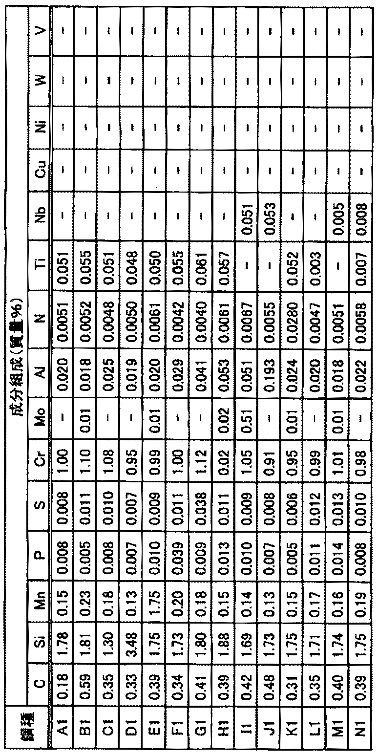
- the base metal is a billet obtained by melting steel having the composition shown in Table 1-1 or Table 1-2 below (the balance is iron and inevitable impurities), and the resulting billet is hot-rolled to obtain a diameter ⁇ Produced a 14 mm rolled wire rod.
- the billet heating temperature was 1100 ° C. and the finish rolling temperature was 850 ° C.
- the part represented by “-” means no addition.
- the obtained rolled wire is subjected to a metal structure in the order of descaling treatment, spheroidizing annealing, descaling treatment, coating treatment, wire drawing, spheroidizing annealing, descaling treatment, coating treatment, and finish wire drawing in accordance with a conventional method. And the wire diameter was adjusted and the steel wire whose diameter (phi) is 11.8 mm was manufactured.
- a flange bolt of M12 mm ⁇ P1.25 mm and neck length L70 mm was produced from the obtained steel wire by cold forging using a multistage former.
- M represents the diameter of the shaft portion
- P represents the pitch.
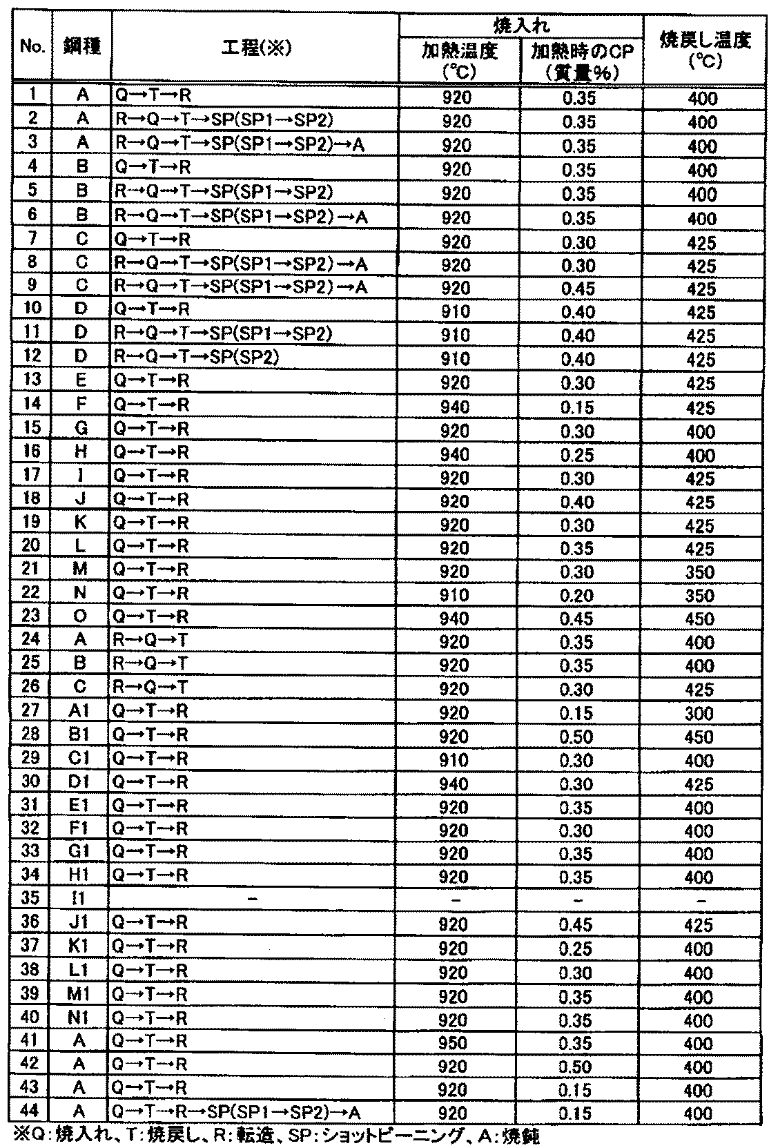
- the obtained flange bolt was processed by changing the conditions and order of quenching Q, tempering T, rolling process R, shot peening SP, annealing A.
- Table 2 below shows the conditions and process order.
- Q means quenching
- T means tempering
- R means rolling
- SP means shot peening
- A means annealing.
- Quenching Q was heated to the temperature shown in Table 2 below, and the carbon potential (CP) during quenching heating was controlled in Table 2 below to perform quenching.
- the heating time for quenching was 20 minutes, and quenching was performed with oil cooling at 60 ° C.
- Tempering T was performed by heating to the temperature shown in Table 2 below. The heating time for tempering was 45 minutes.
- the shot peening SP was performed by combining the following conditions SP1 or SP2. Table 2 below shows specific combinations in the shot peening SP.
- SP1 shot particle size: 100 ⁇ m
- SP2 shot particle size: 50 ⁇ m
- annealing A was performed at a heating temperature of 190 ° C. and a heating time of 30 minutes as necessary.
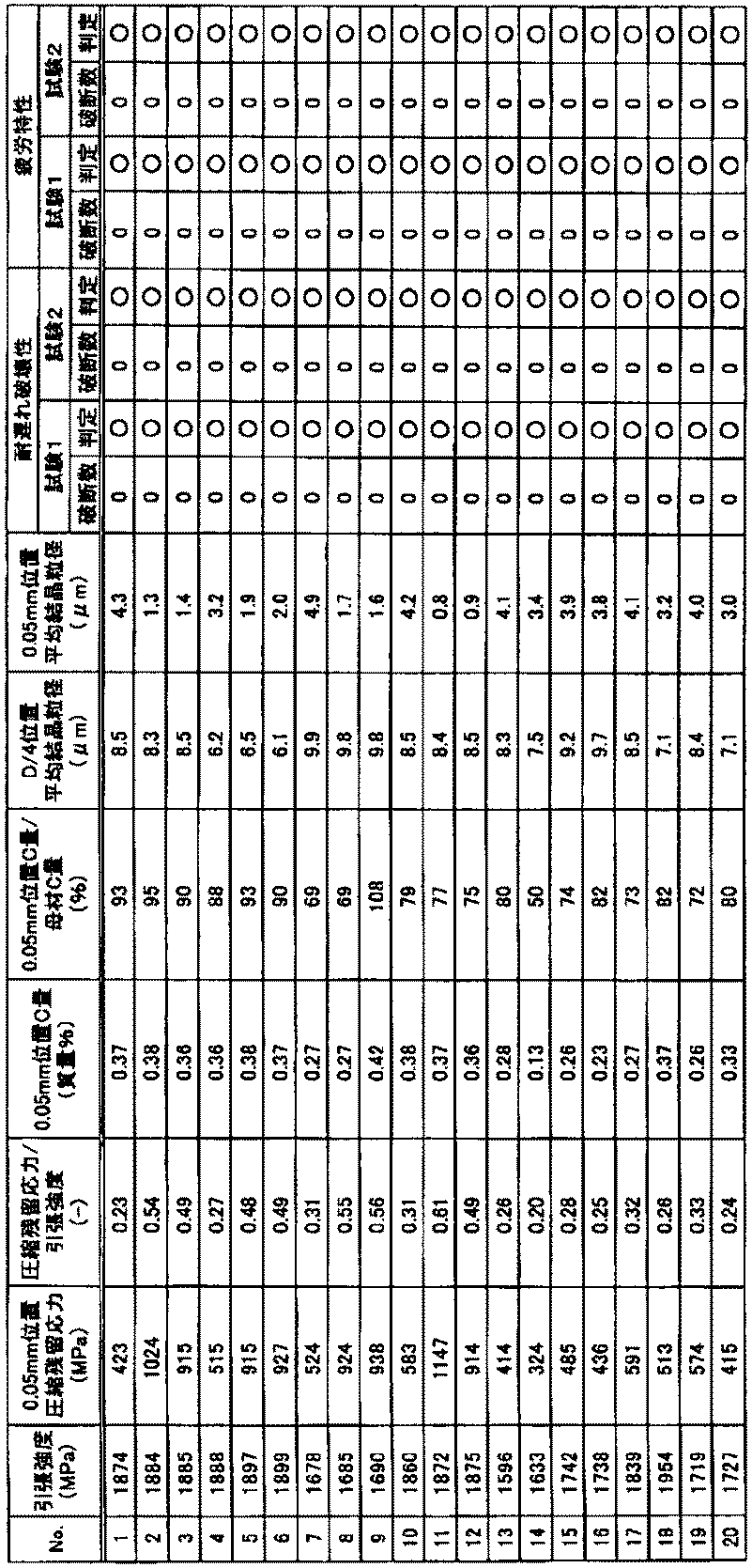
- the tensile strength of the bolt was measured according to JIS B1051 (2009). The results are shown in Table 3-1 or Table 3-2 below. In an example of the present invention, a tensile strength of 1500 MPa or more was considered acceptable.
- the ratio of the compressive residual stress to the tensile strength was calculated, and the results are shown in Table 3-1 or Table 3-2 below. In an example of the present invention, the ratio is 0.15 or more.
- the ratio of the C amount at a depth of 0.05 mm from the screw bottom surface to the C amount of the base material was calculated.
- the results are shown in Table 3-1 or Table 3-2 below.
- the C amount of the base material of the bolt the above ratio was calculated using the C amount shown in Table 1-1 or Table 1-2.
- the obtained bolt was set in a jig incorporating a load cell, and the relation between the rotation angle of the bolt and the axial force was examined by rotating the bolt with a nut runner and tightening the jig. Based on this relationship, the rotation angle at which the axial force applied to the bolt becomes the yield point and the rotation angle at which the axial force applied to the bolt becomes the maximum axial force were obtained.
- the following two levels of delayed fracture tests were performed.
- the conditions of the following delayed fracture test 2 were conditions more severe than the conditions of the following delayed fracture test 1, and the bolts that failed the following delayed fracture test 1 were not subjected to the delayed fracture test 2 below.
- a bolt that passed ( ⁇ ) in the following delayed fracture test 1 was evaluated as being excellent in delayed fracture resistance
- a bolt that passed ( ⁇ ) in the following delayed fracture test 2 was evaluated as delayed fracture resistance. It was evaluated as extremely excellent.
- Delayed fracture test 2 In the delayed fracture test 1, instead of rotating the bolt to the rotation angle at which the axial force applied to the bolt becomes the yield point and tightening the jig, the axial force applied to the bolt is the maximum axial force (bolt rotation angle). The test was performed under the same conditions except that the jig was tightened by rotating the bolt to the rotation angle (maximum axial force in the axial force diagram), and further tightened by + 90 °, and the delayed fracture resistance was evaluated according to the same criteria. The results are shown in Tables 3-1 and 3-2 below.
- the following two levels of fatigue tests were performed using a hydraulic servo pulser.
- the conditions of the following fatigue test 2 were conditions more severe than the conditions of the following fatigue test 1, and the following fatigue test 2 was not performed on the bolts that failed in the following fatigue test 1.
- a bolt that passed ( ⁇ ) in the following fatigue test 1 was evaluated as excellent in fatigue characteristics
- a bolt that passed ( ⁇ ) in the following fatigue test 2 was evaluated as extremely excellent in fatigue characteristics. .
- Fatigue test 1 Fatigue characteristics were evaluated by carrying out the test up to 2 ⁇ 10 6 times with 0.5 times the tensile strength of the bolt as the average stress and the amplitude stress as 16% of the average stress. Each of the five bolts was evaluated, and if one of the five bolts did not break, it was judged as acceptable. In Tables 3-1 and 3-2 below, it was indicated as “ ⁇ ”. A case where one of the five pieces broke was rejected, and in Tables 3-1 and 3-2 below, it was indicated as x.
- No. Nos. 1 to 23 and 42 to 44 are examples satisfying the requirements defined in the present disclosure, and show that they exhibit high strength and excellent delayed fracture resistance and fatigue characteristics. That is, no. As for 1 to 23 and 42 to 44, all are passed on the basis of the delayed fracture test 1 and the fatigue test 1. In particular, no. 42, 43 and Comparing 1 to 23 and 44, delayed fracture resistance is achieved by adjusting the ratio of the C amount at a depth of 0.05 mm from the screw bottom surface of the bolt to 50 to 110% of the C amount of the base material. It can be seen that the fatigue characteristics can be further improved. That is, no. Nos. 1 to 23 and 44 also pass the criteria based on the delayed fracture test 2 and the fatigue test 2.
- No. Nos. 24-41 are examples that do not satisfy any of the requirements stipulated in the present disclosure, and the bolt itself cannot be manufactured, or even if the bolt is manufactured, at least one of strength, delayed fracture resistance, and fatigue characteristics. One characteristic is degraded.
- No. Nos. 24 to 26 are examples in which the compressive residual stress at a depth of 0.05 mm from the screw bottom surface of the bolt was too low in relation to the tensile strength because quenching and tempering were performed after rolling. As a result, delayed fracture resistance and fatigue characteristics could not be improved.
- No. No. 27 is an example in which the amount of C is too small, and even when the tempering temperature was 300 ° C., a tensile strength of 1500 MPa or more could not be secured.
- No. No. 28 is an example in which the amount of C is too much, and the tough ductility of the steel was lowered, so that delayed fracture resistance and fatigue characteristics could not be improved.
- No. No. 29 is an example in which the amount of Si is too small, and coarse cementite was precipitated at the grain boundaries, so that delayed fracture resistance and fatigue characteristics could not be improved.
- No. No. 30 is an example in which the amount of Si is too large, and since ferrite precipitated, fatigue characteristics could not be improved.
- No. No. 31 was an example in which the amount of Mn was too large, and coarse MnS was generated, so that delayed fracture resistance and fatigue characteristics could not be improved.
- No. No. 32 is an example in which the amount of P is too much, and since P is concentrated at the grain boundary and the toughness of the steel is lowered, the delayed fracture resistance cannot be improved.
- No. No. 33 was an example in which the amount of S was too much. Like P, S was concentrated at the grain boundary and the tough ductility of the steel was lowered, so that the delayed fracture resistance could not be improved.
- No. No. 34 is an example in which the amount of Cr was too small, and the corrosion resistance of the steel was lowered, so that the delayed fracture resistance could not be improved.
- No. No. 35 is an example in which the amount of Mo was too large, the hot ductility was lowered, and the wire itself could not be produced.
- No. No. 36 is an example in which the amount of Al was too large, and since coarse nitrides were formed, the fatigue characteristics could not be improved.
- No. No. 37 is an example in which the amount of N is too large, and since coarse nitrides were formed, the fatigue characteristics could not be improved.
- No. Nos. 38 to 40 are examples in which the Ti amount and Nb amount were less than the ranges specified in the present disclosure, and the former austenite crystal grains at the D / 4 position were coarsened, thereby improving delayed fracture resistance and fatigue characteristics. could not.
- No. No. 41 is an example in which the quenching temperature was too high, so that the prior austenite crystal grains at the D / 4 position were coarsened and the toughness of the steel was reduced. As a result, delayed fracture resistance and fatigue characteristics could not be improved.
- the disclosure of the present specification includes the following aspects.
- Aspect: 1 The composition of the base material is mass%, C: 0.25 to 0.5% Si: 1.5 to 3.0%, Mn: 0.1 to 1.5% P: more than 0% and 0.03% or less, S: more than 0% and 0.03% or less, Cr: 0.05 to 1.5%, Mo: 0% or more and less than 0.2%, Al: 0.01 to 0.1%, and N: 0.002 to 0.020%, Furthermore, Containing one or two of Ti: 0.02-0.1% and Nb: 0.02-0.1%, The balance consists of iron and inevitable impurities, The tensile strength is 1500 MPa or more, The compressive residual stress at a depth of 0.05 mm from the screw bottom surface of the bolt is tensile strength ⁇ 0.15 MPa or more, A high-strength bolt excellent in delayed fracture resistance and fatigue characteristics, wherein the average grain size of prior austenite crystal grains at the D / 4 position is 5 to 15 ⁇ m, where D is the diameter of
- Aspect 2 Furthermore, as other elements, The high-strength bolt according to aspect 1, containing one or two of Cu: more than 0% and 0.5% or less and Ni: more than 0% and 1% or less.
- Aspect 3 Furthermore, as other elements, The high-strength bolt according to the aspect 1 or 2, containing one or two of V: more than 0% and 0.5% or less and W: more than 0% and 0.5% or less.
- Aspect 4 The high-strength bolt according to any one of aspects 1 to 3, wherein a ratio of a C amount at a depth of 0.05 mm from a screw bottom surface of the bolt is 50 to 110% with respect to a C amount of the base material.
- a method for producing a high-strength bolt according to any one of aspects 1 to 4 The method for producing a high-strength bolt according to any one of aspects 1 to 4, wherein compressive residual stress is applied by performing at least one selected from rolling and shot peening after quenching and tempering.
- Aspect 6 The production method according to embodiment 5, wherein the quenching is performed in an atmosphere having a carbon potential of 50 to 110% with respect to the C content of the base material.
- Aspect 7 The manufacturing method of the aspect 5 or 6 which anneals, after providing a compressive residual stress.
Landscapes
- Chemical & Material Sciences (AREA)
- Engineering & Computer Science (AREA)
- Materials Engineering (AREA)
- Mechanical Engineering (AREA)
- Metallurgy (AREA)
- Organic Chemistry (AREA)
- Crystallography & Structural Chemistry (AREA)
- Physics & Mathematics (AREA)
- Thermal Sciences (AREA)
- Heat Treatment Of Articles (AREA)
Abstract
1500MPa以上の引張強度を確保したうえで、耐遅れ破壊性および疲労特性に優れた高強度ボルト、およびその製造方法を提供する。 引張強度が1500MPa以上で、ボルトのねじ底表面から深さ0.05mm位置における圧縮残留応力が、引張強度×0.15MPa以上であり、ボルトの軸部における直径をDとしたとき、D/4位置における旧オーステナイト結晶粒の平均粒径が5~15μmであることを特徴とする耐遅れ破壊性および疲労特性に優れた高強度ボルト。
Description
本開示は、自動車や各種産業機械等に用いられるボルトに関する。詳細には、引張強度が1500MPa以上の高強度ボルトについて、耐遅れ破壊性および疲労特性を改善する技術に関する。
自動車や各種産業機械等に用いられるボルトには、高強度化が望まれており、近年では、1500MPa以上の引張強度が必要となっている。
上記ボルトには、高強度化と共に、耐遅れ破壊性の向上も望まれている。遅れ破壊とは、鉄鋼材料に応力が与えられてからある時間を経過した後に発生する破壊である。この原因については、種々の要因が複雑に絡み合っていると考えられるので、その原因を特定することは難しい。即ち、遅れ破壊現象を左右する因子としては、焼戻し温度、組織、材料硬さ、結晶粒度、各種合金元素の影響等が一応認められている。しかしながら、遅れ破壊の防止手段が確立されている訳ではなく、種々の方法が試行錯誤的に提案されているに過ぎないのが実情である。しかし、一般的には、水素脆化現象が関与しているという点で共通の認識が持たれている。
耐遅れ破壊性を改善する技術として、特許文献1および2が提案されている。これらのうち、特許文献1には、引張強さが1400MPa以上で、圧縮残留応力が引張強さの20~95%であり、表面の十点平均粗さが10μm以下に制御した高強度ボルトが提案されている。上記圧縮残留応力を付与する方法としては、ボルト表面にパルスレーザービームを集光および照射する方法が記載されている。
一方、特許文献2には、成分組成として、Moを0.2~1.2%含有したうえで、引張強度125kgf/mm2以上で、鋼材の表面から200μm以内の圧縮残留応力の最大値(σr)が素材の引張強度(σB)に対して、σr/σB≧0.6を満足する高強度機械構造用鋼が提案されている。上記圧縮残留応力を付与する方法としては、ショットピーニングが記載されている。
上記特許文献1では、圧縮残留応力を付与する方法として、ボルト表面にパルスレーザービームを照射する方法を採用しているため、生産性が極めて悪く、工業的に量産することは難しい。また、上記特許文献1の実施例では、焼入れ温度を950℃として熱処理を行っているため、ボルトの旧オーステナイト結晶粒が粗大化し、耐遅れ破壊性を充分に改善できていないと考えられる。
上記特許文献2では、鋼の焼入れ性を得るとともに、焼戻し軟化抵抗を有し、400℃以上の焼戻し温度で125kgf/mm2以上の引張強度を得るためにMoを0.2~1.2%含有している。しかしながら、強度を高めるためにSiを1.5~3.0%含有する鋼種においてMoを0.2%以上添加すると、熱間延性が著しく低下することがあり、工業的に量産することが難しくなることがある。
遅れ破壊は、一般的に、C量が高くなるほど生じやすくなるため、例えば、ボルトの表層を意図的に脱炭させることが考えられる。しかし、表層を脱炭すると、表層の硬さが低下するため、疲労特性が悪化する。よって、耐遅れ破壊性と疲労特性を高いレベルで両立することは困難である。
本開示は、上記の事情に鑑みてなされたものであり、その目的は、1500MPa以上の引張強度を確保したうえで、耐遅れ破壊性および疲労特性に優れた高強度ボルト、およびその製造方法を提供することにある。
上記課題を解決することのできた本開示に係る高強度ボルトとは、母材の成分組成が、質量%で、C:0.25~0.5%、Si:1.5~3.0%、Mn:0.1~1.5%、P:0%超0.03%以下、S:0%超0.03%以下、Cr:0.05~1.5%、Mo:0%以上0.2%未満、Al:0.01~0.1%、およびN:0.002~0.020%を含有し、更に、Ti:0.02~0.1%、およびNb:0.02~0.1%の1種または2種を含有し、残部が鉄および不可避的不純物からなるボルトである。そして、上記ボルトは、引張強度が1500MPa以上で、ボルトのねじ底表面から深さ0.05mm位置における圧縮残留応力が、引張強度×0.15MPa以上であり、ボルトの軸部における直径をDとしたとき、D/4位置における旧オーステナイト結晶粒の平均粒径が5~15μmである点に要旨を有する。
上記ボルトは、更に、質量%で、少なくとも以下の(a)または(b)を満たすように、他の元素を含有してもよい。
(a)Cu:0%超0.5%以下、およびNi:0%超1%以下の1種または2種、
(b)V:0%超0.5%以下、およびW:0%超0.5%以下の1種または2種
(a)Cu:0%超0.5%以下、およびNi:0%超1%以下の1種または2種、
(b)V:0%超0.5%以下、およびW:0%超0.5%以下の1種または2種
上記ボルトのねじ底表面から深さ0.05mm位置におけるC量の割合は、前記母材のC量に対して50~110%であることが好ましい。
本開示に係る高強度ボルトは、焼入れ焼戻し後に、転造加工およびショットピーニングより選ばれる少なくとも一つを行うことによって圧縮残留応力を付与することにより製造できる。前記焼入れは、カーボンポテンシャルが母材のC量に対して50~110%の雰囲気で行なうことが好ましい。上記圧縮残留応力を付与した後は、更に焼鈍してもよい。
本開示によれば、ボルトの成分組成、ボルトのねじ底表面から深さ0.05mm位置における圧縮残留応力、およびボルトの軸部における直径Dに対するD/4位置における旧オーステナイト結晶粒の平均粒径を適切に制御しているため、1500MPa以上の引張強度を確保したうえで、耐遅れ破壊性および疲労特性を高いレベルで両立した高強度ボルトを提供できる。また、本開示によれば、上記高強度ボルトの製造方法も提供できる。
発明者は、引張強度が1500MPa以上の高強度ボルトにおける耐遅れ破壊性および疲労特性を改善するために、鋭意検討を重ねた。その結果、ボルトの成分組成、特に、Si量を1.5~3.0%と高く、Mo量を0.2%未満と低く制御すると共に、ボルトのねじ底表面から深さ0.05mm位置における圧縮残留応力と、ボルトの軸部におけるD/4位置の旧オーステナイト結晶粒の平均粒径を適切に制御すれば、耐遅れ破壊性および疲労特性に優れた引張強度が1500MPa以上の高強度ボルトを実現できることを見出し、本開示を完成した。
まず、本発明の実施形態に係るボルトの母材の成分組成について説明する。本発明の実施形態に係るボルトは、基本成分として、C:0.25~0.5%、Si:1.5~3.0%、Mn:0.1~1.5%、P:0%超0.03%以下、S:0%超0.03%以下、Cr:0.05~1.5%、Mo:0%以上0.2%未満、Al:0.01~0.1%、およびN:0.002~0.020%を含有し、更に、Ti:0.02~0.1%、およびNb:0.02~0.1%の1種または2種を含有する。以下、成分組成における%は質量%を意味する。
Cは、ボルトの強度を確保するのに必要な元素であり、引張強度を1500MPa以上とするために、C量は0.25%以上とする。C量は、好ましくは0.30%以上、より好ましくは0.33%以上である。しかし、Cを過剰に含有すると耐遅れ破壊性および疲労特性が悪化するため、C量は0.5%以下とする。C量は、好ましくは0.45%以下、より好ましくは0.43%以下である。
Siは、脱酸剤として作用すると共に、ボルトの強度を確保するために必要な元素である。また、Siは、粗大なセメンタイトの析出を抑制し、耐遅れ破壊性の向上にも寄与する元素である。また、Siを含有することで、焼入れ焼戻し後の転造加工、転造加工のショットピーニング等によってボルトの表層に高圧縮残留応力を付与できるため、耐遅れ破壊性および疲労特性を向上できる。こうした効果を発揮させるために、Si量は1.5%以上とする。Si量は、好ましくは1.6%以上、より好ましくは1.7%以上である。しかし、Siはフェライトを安定化させる元素であるため、過剰に含有すると焼入れ後にフェライトが析出し、疲労特性が悪化する。従って、本発明の実施形態では、Si量は3.0%以下とする。Si量は、好ましくは2.5%以下、より好ましくは2.0%以下である。
Mnは、ボルトの強度を高めると共に、Sと化合物を形成することによって耐遅れ破壊性を悪化するFeSの生成を抑制する元素である。こうした効果を発揮させるため、Mn量は0.1%以上とする。Mn量は、好ましくは0.13%以上、より好ましくは0.15%以上である。しかし、Mnを過剰に含有するとMnSが粗大化し、応力集中源となって耐遅れ破壊性および疲労特性が悪化する。従って、本発明の実施形態では、Mn量は1.5%以下とする。Mn量は、好ましくは1.3%以下、より好ましくは1.1%以下である。
Pは、不可避的不純物であり、結晶粒界に濃化して鋼の靭延性を低下させ、ボルトの耐遅れ破壊性を悪化する元素である。従って、本発明の実施形態では、P量は0.03%以下とする。P量は、好ましくは0.015%以下、より好ましくは0.010%以下である。P量はできるだけ少ない方が好ましいが、0%とするのは製造上困難であり、通常、0.003%程度は含有する。
SもPと同様、不可避的不純物であり、結晶粒界に濃化して鋼の靭延性を低下させ、ボルトの耐遅れ破壊性を悪化する元素である。従って、本発明の実施形態では、S量は0.03%以下とする。S量は、好ましくは0.015%以下、より好ましくは0.010%以下である。S量はできるだけ少ない方が好ましいが、0%とするのは製造上困難であり、通常、0.003%程度は含有する。
Crは、ボルトの耐食性を向上させ、耐遅れ破壊性を改善するために必要な元素である。こうした効果を得るため、本発明の実施形態では、Cr量は0.05%以上とする。Cr量は、好ましくは0.10%以上、より好ましくは0.20%以上である。しかし、Crを過剰に含有しても効果が飽和するため、コスト高となる。従って、本発明の実施形態では、Cr量は1.5%以下とする。Cr量は、好ましくは1.3%以下、より好ましくは1.1%以下である。
Moは、焼戻し時に微細析出して鋼の靭延性を高め、ボルトの耐遅れ破壊性および疲労特性を改善する元素である。こうした効果を発揮させるため、Mo量は、0%以上とする。Mo量は、好ましくは0.001%以上、より好ましくは0.004%以上、更に好ましくは0.01%以上である。しかし、本発明の実施形態で規定する成分組成においてMoを0.2%以上含有すると、熱間延性が低下し製造できなくなる。また、Moは高価な元素であるため、過剰な添加はコスト高となる。従って、本発明の実施形態では、Mo量は0.2%未満とする。Mo量は、好ましくは0.15%以下、より好ましくは0.10%以下である。
Alは、脱酸剤として作用すると共に、窒化物を形成してピンニング効果により旧オーステナイト結晶粒の粗大化を防止する元素であり、鋼の靭延性が向上し、耐遅れ破壊性および疲労特性を改善できる。こうした効果を発揮させるため、Al量は0.01%以上とする。Al量は、好ましくは0.015%以上、より好ましくは0.020%以上である。しかし、Alを過剰に含有すると粗大な窒化物を形成し、疲労特性を悪化させる。従って、本発明の実施形態では、Al量は0.1%以下とする。Al量は、好ましくは0.08%以下、より好ましくは0.06%以下である。
Nは、Al、Ti、またはNb等と化合して窒化物を形成し、ピンニング効果により旧オーステナイト結晶粒の粗大化を防止する元素であり、鋼の靭延性が向上し、耐遅れ破壊性および疲労特性を改善できる。これらの効果を発揮させるため、N量は0.002%以上とする。N量は、好ましくは0.003%以上、より好ましくは0.0035%以上である。しかし、Nを過剰に含有すると粗大な窒化物を形成し、疲労特性を悪化させる。従って、本発明の実施形態では、N量は0.02%以下とする。N量は、好ましくは0.01%以下、より好ましくは0.008%以下である。
TiおよびNbは、CおよびNと炭窒化物を形成し、ピンニング効果により旧オーステナイト結晶粒の粗大化を防止する元素であり、鋼の靭延性が向上するため、耐遅れ破壊性および疲労特性が向上する。TiとNbは、単独で用いてもよいし、併用してもよい。
Ti量は、0.02%以上とし、好ましくは0.03%以上、より好ましくは0.05%以上である。Nb量は、0.02%以上とし、好ましくは0.03%以上、より好ましくは0.05%以上である。しかし、TiおよびNbを過剰に含有すると、粗大な炭窒化物が形成され、疲労特性が悪化する。従って、本発明の実施形態では、Ti量は、0.1%以下とし、好ましくは0.08%以下、より好ましくは0.06%以下である。Nb量は、0.1%以下とし、好ましくは0.08%以下、より好ましくは0.06%以下である。
本発明の実施形態に係るボルトの基本成分は上記の通りであり、残部は実質的に鉄である。
但し、原料、資材、製造設備等の状況によって持ち込まれる不可避的不純物が鋼中に含まれることは当然に許容される。
本発明の実施形態に係るボルトは、必要に応じて、更に、他の元素として、
(a)Cu:0%超0.5%以下、およびNi:0%超1%以下の1種または2種、
(b)V:0%超0.5%以下、およびW:0%超0.5%以下の1種または2種、
等を含有してもよい。
(a)Cu:0%超0.5%以下、およびNi:0%超1%以下の1種または2種、
(b)V:0%超0.5%以下、およびW:0%超0.5%以下の1種または2種、
等を含有してもよい。
(a)CuおよびNiは、鋼の耐食性を向上させ、ボルトの耐遅れ破壊性を改善するのに作用する元素である。CuとNiは、単独で用いてもよいし、併用してもよい。
Cuは、好ましくは0.05%以上、より好ましくは0.10%以上、更に好ましくは0.13%以上である。しかし、Cuを過剰に含有しても上述した効果は飽和する。また、過剰に含有すると、熱間延性が低下して鋼の生産性が低下する。従って、本発明の実施形態では、Cu量は、好ましくは0.5%以下、より好ましくは0.4%以下、更に好ましくは0.35%以下である。
Niは、好ましくは0.05%以上、より好ましくは0.10%以上、更に好ましくは0.15%以上である。しかし、Niを過剰に含有しても上述した効果は飽和し、コスト高となる。従って、本発明の実施形態では、Ni量は、好ましくは1%以下、より好ましくは0.8%以下、更に好ましくは0.7%以下である。
(b)VおよびWは、炭窒化物を形成してピンニング効果により旧オーステナイト結晶粒の粗大化を防止する元素であり、耐遅れ破壊性および疲労特性を向上させるのに作用する。VとWは、単独で用いてもよいし、併用してもよい。
Vは、好ましくは0.01%以上、より好ましくは0.03%以上、更に好ましくは0.05%以上である。しかし、Vを過剰に含有しても上述した効果は飽和する。また、過剰に含有すると、焼入れ性が高くなりすぎて生産性が悪化する。従って、本発明の実施形態では、V量は、好ましくは0.5%以下、より好ましくは0.3%以下、更に好ましくは0.2%以下である。
Wは、好ましくは0.01%以上、より好ましくは0.05%以上、更に好ましくは0.1%以上である。しかし、Wを過剰に含有しても上述した効果は飽和する。また、過剰に含有すると、焼入れ性が高くなりすぎて生産性が悪化する。従って、本発明の実施形態では、W量は、好ましくは0.5%以下、より好ましくは0.3%以下、更に好ましくは0.2%以下である。
以上、ボルトの母材の成分組成について説明した。
本発明の実施形態に係るボルトは、引張強度が1500MPa以上を前提としている。引張強度は、好ましくは1600MPa以上、より好ましくは1700MPa以上である。引張強度の上限は特に限定されないが、例えば、2200MPa程度である。
そして、本発明の実施形態に係るボルトは、ボルトのねじ底表面から深さ0.05mm位置における圧縮残留応力が、引張強度×0.15MPa以上であると共に、ボルトの軸部における直径をD(mm)としたとき、D/4位置における旧オーステナイト結晶粒の平均粒径が、5~15μmであることが重要である。
(圧縮残留応力:引張強度×0.15MPa以上)
遅れ破壊と疲労破壊は、ボルトの中心部ではなく、表層部が破壊の起点となって発生することが多い。そこで、本発明の実施形態では、ボルトのねじ底表面から深さ0.05mm位置における圧縮残留応力を制御する。具体的には、ねじ底表面から深さ0.05mm位置における圧縮残留応力が、引張強度×0.15MPa以上である。
遅れ破壊と疲労破壊は、ボルトの中心部ではなく、表層部が破壊の起点となって発生することが多い。そこで、本発明の実施形態では、ボルトのねじ底表面から深さ0.05mm位置における圧縮残留応力を制御する。具体的には、ねじ底表面から深さ0.05mm位置における圧縮残留応力が、引張強度×0.15MPa以上である。
上記深さ0.05mm位置に、引張強度×0.15MPa以上の圧縮残留応力を付与することによって、耐遅れ破壊性および疲労特性を向上できる。上記圧縮残留応力は、好ましくは引張強度×0.25MPa以上、より好ましくは引張強度×0.30MPa以上である。上記深さ0.05mm位置における圧縮残留応力は、高ければ高いほど好ましいが、ボルトの引張強度より高くなることはない。上記圧縮残留応力は、おおむね引張強度×0.90MPa以下である。
上記深さ0.05mm位置における圧縮残留応力は、X線残留応力測定法によって測定できる。
(平均粒径:5~15μm)
ボルトの軸部における直径をD(mm)としたとき、D/4位置における旧オーステナイト結晶粒の平均粒径を15μm以下とすることも重要である。D/4位置における金属組織を適切に制御することによって、ボルトの靭延性を向上させることができ、耐遅れ破壊性および疲労特性を向上させることができる。上記平均粒径は、好ましくは10μm以下、より好ましくは8μm以下である。上記D/4位置における旧オーステナイト結晶粒はできるだけ小さい方が好ましいが、本発明の実施形態の成分組成および製造条件を考慮すると、上記平均粒径は、おおむね5μm以上である。
ボルトの軸部における直径をD(mm)としたとき、D/4位置における旧オーステナイト結晶粒の平均粒径を15μm以下とすることも重要である。D/4位置における金属組織を適切に制御することによって、ボルトの靭延性を向上させることができ、耐遅れ破壊性および疲労特性を向上させることができる。上記平均粒径は、好ましくは10μm以下、より好ましくは8μm以下である。上記D/4位置における旧オーステナイト結晶粒はできるだけ小さい方が好ましいが、本発明の実施形態の成分組成および製造条件を考慮すると、上記平均粒径は、おおむね5μm以上である。
本発明の実施形態に係るボルトは、更に、ボルトのねじ底表面から深さ0.05mm位置におけるC量(質量%)の割合が、ボルトの母材におけるC量(質量%)に対して、50~110%であることが好ましい。上記ボルトのねじ底表面から深さ0.05mm位置におけるC量の割合を、前記母材のC量に対して、50%以上とすることによって、表層硬さを一段と高めることができ、疲労特性を一層向上させることができる。上記ボルトのねじ底表面から深さ0.05mm位置におけるC量(質量%)の割合は、前記母材のC量(質量%)に対して、好ましくは60%以上、より好ましくは65%以上である。一方、上記ボルトのねじ底表面から深さ0.05mm位置におけるC量の割合を、前記母材のC量に対して、110%以下とすることによって、表面硬さが硬くなり過ぎるのを抑制できる。その結果、耐遅れ破壊性を一層改善できる。上記ボルトのねじ底表面から深さ0.05mm位置におけるC量(質量%)の割合は、前記母材のC量(質量%)に対して、好ましくは100%以下、より好ましくは95%以下である。
また、本発明の実施形態のボルトは、更に、ボルトのねじ底表面から深さ0.05mm位置における旧オーステナイト結晶粒の平均粒径が0.01~5μmであることが好ましい。ボルトのねじ底表面から深さ0.05mm位置における旧オーステナイト結晶粒の平均粒径を5μm以下とすることによって、遅れ破壊の起点となる部分の靭延性を向上させることができるため、耐遅れ破壊性を向上させることができる。上記平均粒径は、より好ましくは3μm以下、更に好ましくは2μm以下である。ボルトのねじ底表面から深さ0.05mm位置における旧オーステナイト結晶粒は、できるだけ小さい方が好ましいが、本発明の実施形態の成分組成および製造条件を考慮すると、上記平均粒径は、おおむね0.01μm以上である。
次に、本発明の実施形態に係るボルトの製造方法について説明する。
まず、上記化学成分を有する鋼を常法に従って溶製し、鋳造して鋼材とし、熱間圧延して圧延線材を製造する。熱間圧延前の鋼材の加熱温度は特に限定されないが、例えば、900~1100℃とし、線材または棒鋼形状に仕上げ圧延すればよい。仕上げ圧延温度も特に限定されないが、例えば、800~1000℃とすればよい。
次に、得られた圧延線材に、必要に応じて脱スケール処理、球状化焼鈍等の熱処理、皮膜処理および仕上げ伸線加工を施して鋼線を製造する。
次に、得られた鋼線を用い、冷間圧造などによってボルト形状に成形する。
次に、ボルト形状に成形して得られた中間製品に圧縮残留応力を付与することによって本発明の実施形態のボルトが得られる。
本発明の実施形態では、上記中間製品を焼入れ焼戻し後に、転造加工およびショットピーニングより選ばれる少なくとも一つを行うことによって圧縮残留応力を付与することが推奨される。即ち、(a)焼入れ焼戻ししてから転造加工を行うか、(b)焼入れ焼戻ししてからショットピーニングを行うか、(c)焼入れ焼戻ししてから、転造加工とショットピーニングを順不同で行うことによって圧縮残留応力を付与すればよい。
(焼入れQ)
焼入れ時の加熱温度は、安定的にオーステナイト化処理するために、850℃以上とすることが好ましい。焼入れ時の加熱温度は、より好ましくは880℃以上、より好ましくは890℃以上である。しかし、950℃以上の高温に加熱すると、Al、Ti、Nb等によるピンニング効果が低下し、旧オーステナイト結晶粒が粗大化するため、耐遅れ破壊性および疲労特性を改善しにくくなる。従って、本発明の実施形態では、焼入れ時の加熱温度は、950℃未満とすることが好ましい。焼入れ時の加熱温度は、より好ましくは940℃以下、更に好ましくは930℃以下である。
焼入れ時の加熱温度は、安定的にオーステナイト化処理するために、850℃以上とすることが好ましい。焼入れ時の加熱温度は、より好ましくは880℃以上、より好ましくは890℃以上である。しかし、950℃以上の高温に加熱すると、Al、Ti、Nb等によるピンニング効果が低下し、旧オーステナイト結晶粒が粗大化するため、耐遅れ破壊性および疲労特性を改善しにくくなる。従って、本発明の実施形態では、焼入れ時の加熱温度は、950℃未満とすることが好ましい。焼入れ時の加熱温度は、より好ましくは940℃以下、更に好ましくは930℃以下である。
焼入れ加熱時の雰囲気は特に限定されないが、カーボンポテンシャル(以下、「CP」という)は、例えば、ボルトの母材のC量に対して、50~110%に制御することが好ましい。即ち、過度な脱炭が進行すると表層の結晶粒が粗大化し、耐遅れ破壊性および疲労特性が悪化することがある。また、脱炭が更に進行すると、表層にフェライトが析出し、疲労特性が一段と悪化する。過度の脱炭を抑制するためには炉内雰囲気を一酸化炭素と二酸化炭素の混合気とし、炉内のカーボンポテンシャルを制御することが好ましい。CPはボルトの母材のC量に対して、好ましくは50%以上、より好ましくは60%以上、更に好ましくは65%以上である。一方、CPが高くなりすぎると過度な浸炭により耐遅れ破壊性が悪化することがある。従って、本発明の実施形態では、CPはボルトの母材のC量に対して好ましくは110%以下、より好ましくは100%以下、更に好ましくは90%以下である。なお、CPは炉内に設置したコイル状のピアノ線(CPコイル)の炭素量を測定した値である。
(焼戻しT)
焼入れしたままのボルトは、靭性および延性が低いため、焼戻し処理を施す必要がある。焼戻し温度は、300℃以上とすることが好ましい。焼戻し温度は、より好ましくは330℃以上、更に好ましくは350℃以上である。しかし、焼戻し温度が高くなりすぎると旧オーステナイト結晶粒界に粗大なセメンタイトが析出し、耐遅れ破壊性を改善しにくくなる。従って、本発明の実施形態では、焼戻し温度は、480℃以下とすることが好ましい。焼戻し温度は、より好ましくは460℃以下、更に好ましくは450℃以下である。
焼入れしたままのボルトは、靭性および延性が低いため、焼戻し処理を施す必要がある。焼戻し温度は、300℃以上とすることが好ましい。焼戻し温度は、より好ましくは330℃以上、更に好ましくは350℃以上である。しかし、焼戻し温度が高くなりすぎると旧オーステナイト結晶粒界に粗大なセメンタイトが析出し、耐遅れ破壊性を改善しにくくなる。従って、本発明の実施形態では、焼戻し温度は、480℃以下とすることが好ましい。焼戻し温度は、より好ましくは460℃以下、更に好ましくは450℃以下である。
(転造加工R)
焼入れ焼戻しした後、転造加工してねじ部を形成することによって、圧縮残留応力を付与できる。
焼入れ焼戻しした後、転造加工してねじ部を形成することによって、圧縮残留応力を付与できる。
(ショットピーニングSP)
焼入れ焼戻しした後、ショットピーニングすることによって、圧縮残留応力を付与できる。
焼入れ焼戻しした後、ショットピーニングすることによって、圧縮残留応力を付与できる。
ショットピーニングの条件は特に限定されないが、例えば、ショット粒径、投射速度および投射時間を次のように制限することが好ましい。
ショット粒径は、30~150μmとすることが好ましい。ショット粒径を小さくすると、ボルトの表層における圧縮残留応力を大きくすることができ、ショット粒径を大きくすると、ボルトの深部まで圧縮残留応力を付与できる。そこで、本発明の実施形態では、ボルトのねじ底表面から深さ0.05mm位置における圧縮残留応力を、引張強度×0.15MPa以上とするために、ショット粒径を選択すればよい。上記ショット粒径は、好ましくは30μm以上、より好ましくは40μm以上、更に好ましくは45μm以上である。しかし、ショット粒径を大きくし過ぎると、ボルトのねじ部の変形量が大きくなり、ねじの精度が悪くなる。従って、本発明の実施形態では、上記ショット粒径は、150μm以下とすることが好ましい。上記ショット粒径は、より好ましくは130μm以下、更に好ましくは120μm以下である。
投射速度は、30~150m/秒とすることが好ましい。投射速度を大きくすると、ボルトの表層における圧縮残留応力を大きくすることができる。そこで、本発明の実施形態では、ボルトのねじ底表面から深さ0.05mm位置における圧縮残留応力を、引張強度×0.15MPa以上とするために、投射速度を設定すればよい。上記投射速度は、好ましくは30m/秒以上、より好ましくは35m/秒以上、更に好ましくは40m/秒以上である。投射速度は大きければ大きいほど推奨されるが、設備上の制約により、上限は、概ね150m/秒以下となる。
投射時間は、10~60分とすることが好ましい。投射時間を長くするほど、均一な圧縮残留応力を付与できる。従って、本発明の実施形態では、投射時間は、10分以上とすることが好ましい。投射時間は、より好ましくは15分以上、より好ましくは20分以上である。しかし、投射時間を長くしすぎても効果は飽和するため、上限は、例えば、60分以下とすることが好ましい。投射時間は、より好ましくは50分以下、更に好ましくは40分以下である。
ショットピーニングの回数は、1回に限定されず、複数回でもよい。ショットピーニングを複数回行うことで、ボルトの表層の圧縮残留応力を一層高めることができるため、耐遅れ破壊性および疲労特性を一段と改善できる。ショットピーニングを複数回行う場合は、粒径が相対的に大きいショットを用いてボルトの深部まで圧縮残留応力を付与した後、粒径が相対的に小さいショットを用いてボルトの表面粗さを低下させると共に、ボルトの表層に大きな圧縮残留応力を付与することが有効である。
(焼鈍A)
ボルトの表層に圧縮残留応力を付与した後は、必要に応じて焼鈍してもよい。焼鈍することによってボルトの表層における歪みが均一化するため、耐遅れ破壊性および疲労特性を更に向上させることができる。
ボルトの表層に圧縮残留応力を付与した後は、必要に応じて焼鈍してもよい。焼鈍することによってボルトの表層における歪みが均一化するため、耐遅れ破壊性および疲労特性を更に向上させることができる。
焼鈍条件は特に限定されないが、焼鈍温度は、例えば、150~300℃の低温とし、焼鈍時間は、例えば、15~60分とすればよい。
こうして得られたボルトは、引張強度が1500MPa以上で、しかも耐遅れ破壊性および疲労特性に優れているため、自動車、各種産業機械等に好適に用いることができる。
以下、実施例を挙げて本発明の一例をより具体的に説明するが、本開示は下記実施例によって制限を受けるものではなく、前記および後記の趣旨に適合し得る範囲で変更を加えて実施することも勿論可能であり、それらはいずれも本開示の技術的範囲に包含される。
母材が、下記表1-1または表1-2に示す成分組成の鋼(残部は、鉄および不可避的不純物)を溶製してビレットとし、得られたビレットを熱間圧延して直径φが14mmの圧延線材を製造した。ビレットの加熱温度は1100℃、仕上げ圧延温度は850℃とした。尚、下記表1-1および表1-2において、「-」で表した箇所は無添加を意味する。
得られた圧延線材を、常法に従って、脱スケール処理、球状化焼鈍、脱スケール処理、皮膜処理、伸線加工、球状化焼鈍、脱スケール処理、皮膜処理、仕上げ伸線加工の順で金属組織および線径を整え、直径φが11.8mmの鋼線を製造した。
得られた鋼線から多段フォーマーを用いて冷間圧造にて、M12mm×P1.25mmおよび首下長さL70mmのフランジボルトを作製した。なお、Mは軸部の直径、Pはピッチを意味する。
得られたフランジボルトを、焼入れQ、焼戻しT、転造加工R、ショットピーニングSP、焼鈍Aの条件および順番を変えて処理した。下記表2に条件と工程順を示す。下記表2において、Qは焼入れ、Tは焼戻し、Rは転造加工、SPはショットピーニングおよびAは焼鈍を意味している。
焼入れQは、下記表2に示す温度に加熱し、焼入れ加熱時のカーボンポテンシャル(CP)を下記表2に制御し、焼入れを行った。焼入れの加熱時間は20分とし、焼入れは60℃の油冷で行った。
焼戻しTは、下記表2に示す温度に加熱して行った。焼戻しの加熱時間は、45分とした。
ショットピーニングSPは、下記SP1またはSP2の条件を組み合わせて行った。下記表2にショットピーニングSPにおける具体的な組み合わせを示す。
SP1=ショット粒径:100μm、投射速度:50m/秒、投射時間:10分
SP2=ショット粒径:50μm、投射速度:50m/秒、投射時間:10分
SP1=ショット粒径:100μm、投射速度:50m/秒、投射時間:10分
SP2=ショット粒径:50μm、投射速度:50m/秒、投射時間:10分
ショットピーニングSPの後、必要に応じて、加熱温度:190℃および加熱時間:30分として焼鈍Aを行った。
得られたボルトについて、以下の手順で、(1)引張強度、(2)ねじ底表面から深さ0.05mm位置における圧縮残留応力、(3)ねじ底表面から深さ0.05mm位置におけるC量、(4)D/4位置における旧オーステナイト結晶粒の平均粒径、および(5)ねじ底表面から深さ0.05mm位置における旧オーステナイト結晶粒の平均粒径を測定した。
(1)ボルトの引張強度は、JIS B1051(2009年)に従って測定した。結果を下記表3-1または表3-2に示す。本発明の一例では、引張強度が1500MPa以上を合格とした。
(2)ボルトのねじ部について、ねじ底表面から深さ0.05mm位置が露出するように電解研磨し、露出面における圧縮残留応力を、以下の条件でX線残留応力測定法にて測定した。結果を下記表3-1または表3-2に示す。
X線入社方向:ボルト円周方向
出力 :40kV、40mA
照射時間 :60sec
スリット :1.0mm
X線入社方向:ボルト円周方向
出力 :40kV、40mA
照射時間 :60sec
スリット :1.0mm
また、上記引張強度に対する上記圧縮残留応力の比(圧縮残留応力/引張強度)を算出し、結果を下記表3-1または表3-2に示す。本発明の一例では、上記比が0.15以上を合格とする。
(3)ボルトのねじ部を縦断面(ボルトの軸に対して平行な断面)で切断し、ねじ底表面から深さ方向に、EPMA(Electron Probe Micro Anlyzer)ライン分析を行い、ねじ底表面から深さ0.05mm位置におけるC量を測定した。結果を下記表3-1または表3-2に示す。
また、母材のC量に対するねじ底表面から深さ0.05mm位置におけるC量の割合を算出した。結果を下記表3-1または表3-2に示す。なお、ボルトの母材のC量としては、表1-1または表1-2に示したC量を用いて上記割合を算出した。
(4)ボルトの軸部を横断面(ボルトの軸に対して垂直な断面)で切断し、軸部の直径をDとしたとき、D/4位置における任意の0.039mm2の領域を、光学顕微鏡で、観察倍率400倍で観察した。画像解析してD/4位置における旧オーステナイト結晶粒の粒径を測定し、平均値を求めた。結果を下記表3-1または表3-2に示す。
(5)ボルトのねじ部を縦断面(ボルトの軸に対して平行な断面)で切断し、ねじ底表面から深さ0.05mm位置を、走査型電子顕微鏡で、観察倍率5000倍で観察し、電子線後方散乱回折法(Electron Backscatter Diffraction:EBSD)にて観察視野内における旧オーステナイト結晶粒の粒径を測定し、平均値を求めた。EBSD法による測定条件は、次の通りである。結果を下記表3-1または表3-2に示す。
装置名 :TSL製 OIM 結晶方位解析装置(EBSD)
加速電圧:15kV
分析範囲:幅50μm×縦52.5μm
Step:0.15μm
装置名 :TSL製 OIM 結晶方位解析装置(EBSD)
加速電圧:15kV
分析範囲:幅50μm×縦52.5μm
Step:0.15μm
次に、得られたボルトについて、(6)耐遅れ破壊性および(7)疲労特性を評価した。
(6)まず、得られたボルトを、ロードセルを組み込んだ冶具にセットし、ナットランナーでボルトを回転して冶具を締め付けることによってボルトの回転角度と軸力の関係について調べた。そして、この関係に基づいて、ボルトにかかる軸力が降伏点となる回転角度およびボルトにかかる軸力が最大軸力となる回転角度をそれぞれ求めた。次に、以下2水準の遅れ破壊試験を行なった。下記遅れ破壊試験2の条件は、下記遅れ破壊試験1の条件よりも過酷な条件であり、下記遅れ破壊試験1で不合格となったボルトは、下記遅れ破壊試験2は実施しなかった。本発明の一例では、下記遅れ破壊試験1で合格(○)となったボルトを耐遅れ破壊性に優れると評価し、下記遅れ破壊試験2で合格(○)となったボルトを耐遅れ破壊性に極めて優れると評価した。
(遅れ破壊試験1)ボルトにかかる軸力が降伏点となる回転角度までボルトを回転して冶具を締め付けた後、冶具ごとに1%HClに200時間浸漬することにより耐遅れ破壊性を評価した。ボルトは10本ずつ評価した。10本中1本も破断しなかった場合を合格とし、下記表3-1および表3-2では○と表記した。10本中1本でも破断した場合を不合格とし、下記表3-1および表3-2では×と表記した。
(遅れ破壊試験2)上記遅れ破壊試験1において、ボルトにかかる軸力が降伏点となる回転角度までボルトを回転して冶具を締め付ける代わりに、ボルトにかかる軸力が最大軸力(ボルト回転角度-軸力線図における最大軸力)となる回転角度までボルトを回転して冶具を締め付けた後、更に+90°締め付ける以外は同じ条件で試験を行ない、同じ基準で耐遅れ破壊性を評価した。結果を下記表3-1および表3-2に示す。
(7)油圧サーボパルサーを用いて以下2水準の疲労試験を行なった。下記疲労試験2の条件は、下記疲労試験1の条件よりも過酷な条件であり、下記疲労試験1で不合格となったボルトは、下記疲労試験2は実施しなかった。本発明の一例では、下記疲労試験1で合格(○)となったボルトを疲労特性に優れると評価し、下記疲労試験2で合格(○)となったボルトを疲労特性に極めて優れると評価した。
(疲労試験1)ボルトの引張強度の0.5倍を平均応力とし、振幅応力は平均応力の16%として2×10⁶回まで実施することで疲労特性を評価した。ボルトは5本ずつ評価し、5本中1本も破断しなかった場合を合格とし、下記表3-1および表3-2では○と表記した。5本中1本でも破断した場合を不合格とし、下記表3-1および表3-2では×と表記した。
(疲労試験2)上記疲労試験1において、ボルトの引張強度の0.5倍を平均応力とする代わりに、ボルトの引張強度の0.6倍を平均応力とする以外は同じ条件で試験を行ない、同じ基準で疲労特性を評価した。結果を下記表3-1および表3-2に示す。
下記表1-1、表1-2、表2、表3-1、および表3-2から、次のように考察できる。
No.1~23、42~44は、本開示で規定する要件を満足する例であり、高強度で、且つ優れた耐遅れ破壊性および疲労特性を発揮していることが分かる。即ち、No.1~23、42~44は、いずれも遅れ破壊試験1および疲労試験1による基準で合格となっている。特に、No.42、43と、No.1~23、44を比較すると、ボルトのねじ底表面から深さ0.05mm位置におけるC量の割合が、母材のC量に対して50~110%に調整することによって、耐遅れ破壊性および疲労特性を一段と向上できることが分かる。即ち、No.1~23、44は、遅れ破壊試験2および疲労試験2による基準においても合格となっている。
これに対し、No.24~41は、本開示で規定するいずれかの要件を満足しない例であり、ボルトの製造自体ができないか、ボルトを製造しても、強度、耐遅れ破壊性、および疲労特性のうち少なくとも一つの特性が劣化している。
これらのうち、No.24~26は、転造してから焼入焼戻しを行ったため、ボルトのねじ底表面から深さ0.05mm位置における圧縮残留応力が、引張強度との関係で低すぎた例である。その結果、耐遅れ破壊性および疲労特性を改善できなかった。
No.27は、C量が少なすぎる例であり、焼戻し温度を300℃としても1500MPa以上の引張強度を確保できなかった。
No.28は、C量が多すぎる例であり、鋼の靭延性が低下したため、耐遅れ破壊性および疲労特性を改善できなかった。
No.29は、Si量が少なすぎる例であり、結晶粒界に粗大なセメンタイトが析出したため、耐遅れ破壊性および疲労特性を改善できなかった。
No.30は、Si量が多すぎる例であり、フェライトが析出したため、疲労特性を改善できなかった。
No.31は、Mn量が多すぎた例であり、粗大なMnSが生成したため、耐遅れ破壊性および疲労特性を改善できなかった。
No.32は、P量が多すぎた例であり、Pが結晶粒界に濃化し、鋼の靭延性が低下したため、耐遅れ破壊性を改善できなかった。
No.33は、S量が多すぎた例であり、Pと同様、Sが結晶粒界に濃化し、鋼の靭延性が低下したため、耐遅れ破壊性を改善できなかった。
No.34は、Cr量が少なすぎた例であり、鋼の耐食性が低下したため、耐遅れ破壊性を改善できなかった。
No.35は、Mo量が多すぎた例であり、熱間延性が低下し、線材自体を製造できなかった。
No.36は、Al量が多すぎた例であり、粗大な窒化物が形成されたため、疲労特性を改善できなかった。
No.37は、N量が多すぎた例であり、粗大な窒化物が形成されたため、疲労特性を改善できなかった。
No.38~40は、Ti量およびNb量が本開示で規定する範囲を下回り、少なすぎた例であり、D/4位置における旧オーステナイト結晶粒が粗大化したため、耐遅れ破壊性および疲労特性を改善できなかった。
No.41は、焼入れ温度が高すぎたため、D/4位置における旧オーステナイト結晶粒が粗大化し、鋼の靭延性が低下した例である。その結果、耐遅れ破壊性および疲労特性を改善できなかった。


本明細書の開示内容は、以下の態様を含む。
態様:1
母材の成分組成が、質量%で、
C :0.25~0.5%、
Si:1.5~3.0%、
Mn:0.1~1.5%、
P :0%超0.03%以下、
S :0%超0.03%以下、
Cr:0.05~1.5%、
Mo:0%以上0.2%未満、
Al:0.01~0.1%、および
N :0.002~0.020%を含有し、
更に、
Ti:0.02~0.1%、および
Nb:0.02~0.1%の1種または2種を含有し、
残部が鉄および不可避的不純物からなり、
引張強度が1500MPa以上で、
ボルトのねじ底表面から深さ0.05mm位置における圧縮残留応力が、引張強度×0.15MPa以上であり、
ボルトの軸部における直径をDとしたとき、D/4位置における旧オーステナイト結晶粒の平均粒径が5~15μmであることを特徴とする耐遅れ破壊性および疲労特性に優れた高強度ボルト。
態様2:
更に、他の元素として、質量%で、
Cu:0%超0.5%以下、および
Ni:0%超1%以下の1種または2種を含有する態様1に記載の高強度ボルト。
態様3:
更に、他の元素として、質量%で、
V :0%超0.5%以下、および
W :0%超0.5%以下の1種または2種を含有する態様1または2に記載の高強度ボルト。
態様4:
ボルトのねじ底表面から深さ0.05mm位置におけるC量の割合が、前記母材のC量に対して50~110%である態様1~3のいずれかに記載の高強度ボルト。
態様5:
態様1~4のいずれかに記載の高強度ボルトの製造方法であって、
焼入れ焼戻し後に、転造加工およびショットピーニングより選ばれる少なくとも一つを行うことによって圧縮残留応力を付与することを特徴とする態様1~4のいずれかに記載の高強度ボルトの製造方法。
態様6:
前記焼入れは、カーボンポテンシャルが母材のC量に対して50~110%の雰囲気で行なう態様5に記載の製造方法。
態様7:
圧縮残留応力を付与した後、焼鈍する態様5または6に記載の製造方法。
態様:1
母材の成分組成が、質量%で、
C :0.25~0.5%、
Si:1.5~3.0%、
Mn:0.1~1.5%、
P :0%超0.03%以下、
S :0%超0.03%以下、
Cr:0.05~1.5%、
Mo:0%以上0.2%未満、
Al:0.01~0.1%、および
N :0.002~0.020%を含有し、
更に、
Ti:0.02~0.1%、および
Nb:0.02~0.1%の1種または2種を含有し、
残部が鉄および不可避的不純物からなり、
引張強度が1500MPa以上で、
ボルトのねじ底表面から深さ0.05mm位置における圧縮残留応力が、引張強度×0.15MPa以上であり、
ボルトの軸部における直径をDとしたとき、D/4位置における旧オーステナイト結晶粒の平均粒径が5~15μmであることを特徴とする耐遅れ破壊性および疲労特性に優れた高強度ボルト。
態様2:
更に、他の元素として、質量%で、
Cu:0%超0.5%以下、および
Ni:0%超1%以下の1種または2種を含有する態様1に記載の高強度ボルト。
態様3:
更に、他の元素として、質量%で、
V :0%超0.5%以下、および
W :0%超0.5%以下の1種または2種を含有する態様1または2に記載の高強度ボルト。
態様4:
ボルトのねじ底表面から深さ0.05mm位置におけるC量の割合が、前記母材のC量に対して50~110%である態様1~3のいずれかに記載の高強度ボルト。
態様5:
態様1~4のいずれかに記載の高強度ボルトの製造方法であって、
焼入れ焼戻し後に、転造加工およびショットピーニングより選ばれる少なくとも一つを行うことによって圧縮残留応力を付与することを特徴とする態様1~4のいずれかに記載の高強度ボルトの製造方法。
態様6:
前記焼入れは、カーボンポテンシャルが母材のC量に対して50~110%の雰囲気で行なう態様5に記載の製造方法。
態様7:
圧縮残留応力を付与した後、焼鈍する態様5または6に記載の製造方法。
本出願は、出願日が2015年12月1日である日本国特許出願、特願第2015-235196号を基礎出願とする優先権主張を伴う。特願第2015-235196号は参照することにより本明細書に取り込まれる。
Claims (6)
- 母材の成分組成が、質量%で、
C :0.25~0.5%、
Si:1.5~3.0%、
Mn:0.1~1.5%、
P :0%超0.03%以下、
S :0%超0.03%以下、
Cr:0.05~1.5%、
Mo:0%以上0.2%未満、
Al:0.01~0.1%、および
N :0.002~0.020%を含有し、
更に、
Ti:0.02~0.1%、および
Nb:0.02~0.1%の1種または2種を含有し、
残部が鉄および不可避的不純物からなり、
引張強度が1500MPa以上で、
ボルトのねじ底表面から深さ0.05mm位置における圧縮残留応力が、引張強度×0.15MPa以上であり、
ボルトの軸部における直径をDとしたとき、D/4位置における旧オーステナイト結晶粒の平均粒径が5~15μmであることを特徴とする耐遅れ破壊性および疲労特性に優れた高強度ボルト。 - 更に、質量%で、少なくとも以下の(a)または(b)を満たすように、他の元素を含有する請求項1に記載の高強度ボルト。
(a)Cu:0%超0.5%以下、およびNi:0%超1%以下の1種または2種
(b)V:0%超0.5%以下、およびW:0%超0.5%以下の1種または2種 - ボルトのねじ底表面から深さ0.05mm位置におけるC量の割合が、前記母材のC量に対して50~110%である請求項1または2に記載の高強度ボルト。
- 請求項1または2に記載の高強度ボルトの製造方法であって、
焼入れ焼戻し後に、転造加工およびショットピーニングより選ばれる少なくとも一つを行うことによって圧縮残留応力を付与することを特徴とする請求項1または2に記載の高強度ボルトの製造方法。 - 前記焼入れは、カーボンポテンシャルが母材のC量に対して50~110%の雰囲気で行なう請求項4に記載の製造方法。
- 圧縮残留応力を付与した後、焼鈍する請求項4に記載の製造方法。
Applications Claiming Priority (2)
| Application Number | Priority Date | Filing Date | Title |
|---|---|---|---|
| JP2015-235196 | 2015-12-01 | ||
| JP2015235196A JP6454635B2 (ja) | 2015-12-01 | 2015-12-01 | 耐遅れ破壊性および疲労特性に優れた高強度ボルト、およびその製造方法 |
Publications (1)
| Publication Number | Publication Date |
|---|---|
| WO2017094675A1 true WO2017094675A1 (ja) | 2017-06-08 |
Family
ID=58796744
Family Applications (1)
| Application Number | Title | Priority Date | Filing Date |
|---|---|---|---|
| PCT/JP2016/085217 Ceased WO2017094675A1 (ja) | 2015-12-01 | 2016-11-28 | 耐遅れ破壊性および疲労特性に優れた高強度ボルト、およびその製造方法 |
Country Status (3)
| Country | Link |
|---|---|
| JP (1) | JP6454635B2 (ja) |
| TW (1) | TWI612149B (ja) |
| WO (1) | WO2017094675A1 (ja) |
Cited By (1)
| Publication number | Priority date | Publication date | Assignee | Title |
|---|---|---|---|---|
| CN121065460A (zh) * | 2025-10-28 | 2025-12-05 | 福建省华盖机械制造有限公司 | 一种抗疲劳汽配螺栓及其热处理加工工艺 |
Families Citing this family (6)
| Publication number | Priority date | Publication date | Assignee | Title |
|---|---|---|---|---|
| CN111663084A (zh) * | 2020-06-29 | 2020-09-15 | 马鞍山钢铁股份有限公司 | 一种含钛16.9级螺栓用圆钢及其生产方法 |
| JP7757138B2 (ja) | 2020-11-10 | 2025-10-21 | Jfeスチール株式会社 | 高圧ガス用容器およびその製造方法 |
| CN112695241A (zh) * | 2020-11-25 | 2021-04-23 | 南京钢铁股份有限公司 | 12.9级抗延迟断裂耐候螺栓钢及制备方法 |
| CN112795854A (zh) * | 2020-12-23 | 2021-05-14 | 石家庄钢铁有限责任公司 | 高强度紧固件螺栓用钢及其生产方法 |
| CN116262961A (zh) * | 2021-12-14 | 2023-06-16 | 苏州剑派实业有限公司 | 一种用于变速箱的内六角螺栓及其生产工艺 |
| CN117549010A (zh) * | 2023-12-26 | 2024-02-13 | 鹏驰五金制品(昆山)有限公司 | 一种六爪螺栓及其牙纹加工方法 |
Citations (6)
| Publication number | Priority date | Publication date | Assignee | Title |
|---|---|---|---|---|
| JPH07292434A (ja) * | 1994-04-22 | 1995-11-07 | Nippon Steel Corp | 耐遅れ破壊特性及び耐水素侵入性に優れた高強度機械構造用鋼及びその製造方法 |
| JP2006131990A (ja) * | 2004-10-08 | 2006-05-25 | Nippon Steel Corp | 耐遅れ破壊特性に優れた高強度ボルトおよびその耐遅れ破壊特性向上方法 |
| JP2006291295A (ja) * | 2005-04-11 | 2006-10-26 | Nippon Steel Corp | 耐遅れ破壊特性に優れた高強度ボルトおよびその製造方法 |
| JP2012017484A (ja) * | 2010-07-06 | 2012-01-26 | Kobe Steel Ltd | ボルト用鋼、ボルトおよびボルトの製造方法 |
| JP2013163865A (ja) * | 2012-01-11 | 2013-08-22 | Kobe Steel Ltd | ボルトおよびボルトの製造方法 |
| JP2015014031A (ja) * | 2013-07-05 | 2015-01-22 | 株式会社神戸製鋼所 | ボルト用鋼およびボルト、並びにそれらの製造方法 |
-
2015
- 2015-12-01 JP JP2015235196A patent/JP6454635B2/ja not_active Expired - Fee Related
-
2016
- 2016-11-28 WO PCT/JP2016/085217 patent/WO2017094675A1/ja not_active Ceased
- 2016-11-30 TW TW105139497A patent/TWI612149B/zh not_active IP Right Cessation
Patent Citations (6)
| Publication number | Priority date | Publication date | Assignee | Title |
|---|---|---|---|---|
| JPH07292434A (ja) * | 1994-04-22 | 1995-11-07 | Nippon Steel Corp | 耐遅れ破壊特性及び耐水素侵入性に優れた高強度機械構造用鋼及びその製造方法 |
| JP2006131990A (ja) * | 2004-10-08 | 2006-05-25 | Nippon Steel Corp | 耐遅れ破壊特性に優れた高強度ボルトおよびその耐遅れ破壊特性向上方法 |
| JP2006291295A (ja) * | 2005-04-11 | 2006-10-26 | Nippon Steel Corp | 耐遅れ破壊特性に優れた高強度ボルトおよびその製造方法 |
| JP2012017484A (ja) * | 2010-07-06 | 2012-01-26 | Kobe Steel Ltd | ボルト用鋼、ボルトおよびボルトの製造方法 |
| JP2013163865A (ja) * | 2012-01-11 | 2013-08-22 | Kobe Steel Ltd | ボルトおよびボルトの製造方法 |
| JP2015014031A (ja) * | 2013-07-05 | 2015-01-22 | 株式会社神戸製鋼所 | ボルト用鋼およびボルト、並びにそれらの製造方法 |
Cited By (1)
| Publication number | Priority date | Publication date | Assignee | Title |
|---|---|---|---|---|
| CN121065460A (zh) * | 2025-10-28 | 2025-12-05 | 福建省华盖机械制造有限公司 | 一种抗疲劳汽配螺栓及其热处理加工工艺 |
Also Published As
| Publication number | Publication date |
|---|---|
| TWI612149B (zh) | 2018-01-21 |
| TW201732052A (zh) | 2017-09-16 |
| JP6454635B2 (ja) | 2019-01-16 |
| JP2017101284A (ja) | 2017-06-08 |
Similar Documents
| Publication | Publication Date | Title |
|---|---|---|
| US11203797B2 (en) | Steel wire and wire rod | |
| JP6454635B2 (ja) | 耐遅れ破壊性および疲労特性に優れた高強度ボルト、およびその製造方法 | |
| JP5482971B2 (ja) | 冷間鍛造性に優れた鋼線材または棒鋼 | |
| JP5674620B2 (ja) | ボルト用鋼線及びボルト、並びにその製造方法 | |
| KR102021216B1 (ko) | 산세성 및 담금질 템퍼링 후의 내지연파괴성이 우수한 볼트용 선재, 및 볼트 | |
| RU2733612C2 (ru) | Сталь, продукт, произведенный из такой стали, и способ его изготовления | |
| JP6267618B2 (ja) | ボルト用鋼およびボルト | |
| WO2015083599A1 (ja) | ボルト用鋼線およびボルト、並びにそれらの製造方法 | |
| KR20000028786A (ko) | 고강도 스프링용 강선 및 그 제조 방법 | |
| JP6065121B2 (ja) | 高炭素熱延鋼板およびその製造方法 | |
| JP6461672B2 (ja) | 冷間圧造性、および焼入れ焼戻し後の耐遅れ破壊性に優れたボルト用鋼線、並びにボルト | |
| KR20140129081A (ko) | 연질화용 강 및 이 강을 소재로 하는 연질화 부품 | |
| WO2015001950A1 (ja) | ボルト用鋼およびボルト、並びにそれらの製造方法 | |
| JP2020125538A (ja) | 冷間加工用機械構造用鋼およびその製造方法 | |
| WO2017090738A1 (ja) | 鋼、浸炭鋼部品、及び浸炭鋼部品の製造方法 | |
| WO2017090731A1 (ja) | 鋼、浸炭鋼部品、及び浸炭鋼部品の製造方法 | |
| WO2018061101A1 (ja) | 鋼 | |
| JPWO2020090149A1 (ja) | ボルト用鋼 | |
| JP7610175B1 (ja) | 鋼線及び機械部品 |
Legal Events
| Date | Code | Title | Description |
|---|---|---|---|
| 121 | Ep: the epo has been informed by wipo that ep was designated in this application |
Ref document number: 16870612 Country of ref document: EP Kind code of ref document: A1 |
|
| NENP | Non-entry into the national phase |
Ref country code: DE |
|
| 122 | Ep: pct application non-entry in european phase |
Ref document number: 16870612 Country of ref document: EP Kind code of ref document: A1 |