WO2017094450A1 - ぬいぐるみ - Google Patents
ぬいぐるみ Download PDFInfo
- Publication number
- WO2017094450A1 WO2017094450A1 PCT/JP2016/082961 JP2016082961W WO2017094450A1 WO 2017094450 A1 WO2017094450 A1 WO 2017094450A1 JP 2016082961 W JP2016082961 W JP 2016082961W WO 2017094450 A1 WO2017094450 A1 WO 2017094450A1
- Authority
- WO
- WIPO (PCT)
- Prior art keywords
- accessory
- stuffed toy
- unit
- mounting
- stuffed
- Prior art date
- Legal status (The legal status is an assumption and is not a legal conclusion. Google has not performed a legal analysis and makes no representation as to the accuracy of the status listed.)
- Ceased
Links
Images




Classifications
-
- A—HUMAN NECESSITIES
- A63—SPORTS; GAMES; AMUSEMENTS
- A63H—TOYS, e.g. TOPS, DOLLS, HOOPS OR BUILDING BLOCKS
- A63H3/00—Dolls
- A63H3/02—Dolls made of fabrics or stuffed
-
- A—HUMAN NECESSITIES
- A63—SPORTS; GAMES; AMUSEMENTS
- A63H—TOYS, e.g. TOPS, DOLLS, HOOPS OR BUILDING BLOCKS
- A63H29/00—Drive mechanisms for toys in general
- A63H29/22—Electric drives
-
- A—HUMAN NECESSITIES
- A63—SPORTS; GAMES; AMUSEMENTS
- A63H—TOYS, e.g. TOPS, DOLLS, HOOPS OR BUILDING BLOCKS
- A63H3/00—Dolls
- A63H3/36—Details; Accessories
- A63H3/52—Dolls' houses, furniture or other equipment; Dolls' clothing or footwear
Definitions
- the present invention relates to a stuffed animal, that is, a toy that wraps an object inside and imitates the shape of a person, an animal, an imaginary character or the like.
- a stuffed animal with a built-in computer is known (for example, see Patent Document 1).
- the stuffed animal described in Patent Document 1 includes a tag reader that reads identification information from an accessory in which an RFID tag chip is embedded, and performs a predetermined effect according to the identification information read in a non-contact manner from the accessory.
- the present invention has been made in view of the above circumstances, and an object of the present invention is to provide a stuffed toy that can prevent the loss of accessories for performing production and can reduce the manufacturing cost.
- the stuffed toy according to the present invention includes a main body portion having a surface formed of a first material, and a mounting portion provided on the main body portion, to which an accessory can be attached and detached, wherein the mounting portion includes the first material. It is characterized by being made of a harder second material.
- the main body portion has a first internal space in which a unit including at least a battery housing portion is accommodated, and the main body portion is viewed in the attachment direction of the accessory to the attachment portion.
- the mounting portion overlaps the unit accommodated in the first internal space.
- the first internal space has an opening that can be opened and closed, and the unit is configured such that a part of the unit can be pulled out from the opening. Yes.
- the stuffed toy according to the present invention is characterized in that a power supply operation unit for switching start and stop of the stuffed toy is formed on the end surface of the unit on the opening side.
- the stuffed toy according to the present invention includes an effect part that produces an effect according to the accessory attached to the attachment part, and the effect part is different from the first internal space in the main body part. It is characterized by being housed in a space.
- the stuffed toy according to the present invention includes the main body portion including a head portion, a torso portion, a pair of hand portions extending from the torso portion, and a pair of leg portions extending from the torso portion, and the first internal space. Is provided in the body part, and is accommodated in each of the pair of hand parts, or an operation part provided at a tip part of each of the pair of legs, and the operation part and the first internal space. And a wiring for connecting the unit.
- the stuffed toy according to the present invention is characterized in that the portion of the main body portion on which the operation portion is provided is urged by the wiring in a direction opposite to the attachment direction of the accessory to the attachment portion.
- the main body portion includes a head portion, a torso portion, a pair of hand portions extending from the torso portion, and a pair of leg portions extending from the torso portion. It is provided in the trunk
- the stuffed toy according to the present invention is characterized by further comprising a control unit that performs a first control to execute an effect according to the accessory when the accessory is mounted on the mounting unit.
- the stuffed toy according to the present invention is executed by the first control after the production is performed by the first control or when the accessory is removed from the mounting unit. It is characterized by performing second control for executing an effect different from the effect.
- the stuffed toy according to the present invention includes an operation unit, and the control unit does not perform any of attachment of an accessory to the attachment unit, removal of an accessory from the attachment unit, and operation of the operation unit. Based on the above, the stuffed toy is shifted to the power saving mode.
- the control unit in the power saving mode, may perform any of attachment of the accessory to the attachment unit, removal of the accessory from the attachment unit, and operation of the operation unit.
- the power saving mode is canceled on the condition that
- the stuffed toy according to the present invention is characterized in that the accessory is formed with a projection showing predetermined information.
- the accessory has a first fitting portion and a second fitting portion to be fitted to the mounting portion, and the protrusion is formed with the first fitting portion. It is formed between said 2nd fitting parts, It is characterized by the above-mentioned.
- FIG. 1 It is an external view which shows typically schematic structure of the stuffed toy 100 which is one Embodiment of this invention. It is an expansion perspective view of the mounting part 21 of the stuffed toy 100 shown in FIG. It is a perspective view which shows schematic structure of the accessory 50 which can be attached or detached to the mounting part 21 shown in FIG. It is a figure which shows schematic structure of the interior space enclosed with the surface of the stuffed toy 100 shown in FIG. It is a left view of the stuffed toy 100 shown in FIG. It is a right view of the stuffed toy 100 shown in FIG.
- FIG. 2 is a schematic cross-sectional view taken along line AA of the stuffed animal 100 shown in FIG. 1.
- FIG. 4 It is a figure which shows the state which cancelled
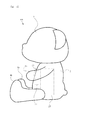
- FIG. 1 is an external view schematically showing a schematic configuration of a stuffed animal 100 according to an embodiment of the present invention.
- the stuffed toy 100 has a shape imitating the shape of a person, an animal, an imaginary character, or the like (in the example of FIG. 1, a bear shape), a torso part 2, a head 1 extending from the torso part 2, 2 includes a main body portion 100a including a pair of hand portions 3a and 3b extending from 2 and a pair of leg portions 4a and 4b extending from the body portion 2, and a mounting portion 21 fixed to the surface of the main body portion 100a.
- the main body 100a is made of a cloth whose surface is formed of a soft first material such as cotton or chemical fiber, and an elastic filling material is packed into a part of the internal space wrapped with the cloth. It is.
- the mounting part 21 is provided in the trunk
- the mounting portion 21 is made of a second material (for example, plastic) that is harder than the first material that constitutes the surface of the main body portion 100a.
- Operation portions 3c and 3d for operating the stuffed toy 100 are formed inside the tip portions of the hand portion 3a and the hand portion 3b.
- Each of the operation units 3c and 3d is configured by, for example, a pressure-sensitive sensor, and detects pressure and outputs a detection signal to the control unit 24 described later.
- a light emitting part 22 as a production part is incorporated in a part closer to the leg parts 4a and 4b than a part in which the mounting part 21 is provided.
- FIG. 2 is an enlarged perspective view of the mounting portion 21 of the stuffed toy 100 shown in FIG.
- FIG. 3 is a perspective view showing a schematic configuration of the accessory 50 that can be attached to and detached from the mounting portion 21 shown in FIG.
- the mounting part 21 includes a convex part 21a and a convex part 21b arranged in the direction in which the head part 1 and the body part 2 are arranged, and a switch part 21c formed between the convex part 21a and the convex part 21b.
- the accessory 50 includes a concave portion 50a which is a first fitting portion fitted to the convex portion 21a, a concave portion 50b which is a second fitting portion fitted to the convex portion 21b, and the concave portion 50a and the concave portion 50b. A projection 50c formed therebetween.
- the protrusion 50c is formed into a pattern indicating predetermined information, and a plurality of accessories 50 having different patterns of the protrusion 50c can be attached to and detached from the mounting portion 21.
- the switch part 21c of the mounting part 21 has a plurality of switches (switches S1 to S5) that can be pushed in.
- switches S1 to S5 When the accessory 50 shown in FIG. 3 is mounted on the mounting portion 21, the convex portion 21a and the concave portion 50a are fitted, and the convex portion 21b and the concave portion 50b are fitted, the switches S1 to S3 are switched by the projection 50c of the accessory 50. Pushed in. Depending on the pattern of the protrusions 50c formed on the accessory 50, the switch to be pushed changes.
- the switch unit 21c notifies the control unit 24, which will be described later, of the signal corresponding to the combination of the number of switches pushed in by the attachment of the accessory 50 and the position of the switch as accessory identification information.
- the direction in which the accessory 50 is pushed into the mounting unit 21 when the accessory 50 is mounted on the mounting unit 21 is referred to as a mounting direction of the accessory 50 to the mounting unit 21 and is simply referred to as a mounting direction hereinafter.
- FIG. 4 is a diagram showing a schematic configuration of the internal space wrapped by the surface of the stuffed animal 100 shown in FIG.
- a control unit 23 including a control unit that performs overall control of the stuffed animal 100, operation units 3 c and 3 d, each of the operation units 3 c and 3 d, and the control unit 23 Wirings H1 and H2 are provided.
- the length of the wiring H1 is adjusted to urge the hand portion 3b in the direction opposite to the mounting direction.
- the length of the wiring H2 is adjusted to bias the hand portion 3a toward the direction opposite to the mounting direction.
- FIG. 5 is a left side view of the stuffed animal 100 shown in FIG.
- FIG. 6 is a right side view of the stuffed toy 100 shown in FIG.
- the hands 3a and 3b are urged in the opposite direction of the mounting direction (the direction from left to right in FIG. 5) by the wirings H1 and H2 shown in FIG. ing. Thereby, the cuteness of the stuffed animal 100 is produced.
- the mounting portion 21 is provided at a position (position where it can be held) between the hand portion 3 a and the hand portion 3 b when the body portion 2 is viewed in the mounting direction.
- the wiring portions H1 and H2 are designed so that the hand portion 3a and the hand portion 3b can be bent to the vicinity of the front of the mounting portion 21, respectively.
- the mounting part 21 is provided at a position sandwiched between the hand part 3a and the hand part 3b, so that the mounting part made of a relatively hard material when the main body part 100a is gripped by hand. It is possible to obtain a state in which the periphery of 21 is covered with the hand portions 3a and 3b made of a relatively soft material. As a result, the hand holding the main body 100a can be prevented from coming into contact with the mounting portion 21, and the safety when handling the stuffed toy 100 can be improved. Moreover, the feeling when holding the stuffed toy 100 can be made favorable.
- FIG. 7 is a schematic cross-sectional view taken along line AA of the stuffed animal 100 shown in FIG.
- a first internal space 41 and a second internal space 42 are formed in the vicinity of the end of the body portion 2 on the side opposite to the head 1 side.
- the second internal space 42 is a space surrounded by the fabric 32 to which the mounting portion 21 is fixed and the fabrics 33 and 34 provided in the body portion 2.
- the light emitting unit 22 described above is formed in the second internal space 42.
- the first internal space 41 is surrounded by the fabric 31 that forms the surface on the back side of the stuffed toy 100, the fabrics 33 and 34 provided in the body portion 2, and the fabric 32 to which the mounting portion 21 is fixed. It is space.
- the end portion 32a of the fabric 32 extends to the top of the fabric 31, and the front end portion 32a can be attached to the fabric 31 with a hook-and-loop fastener or the like.
- the opening 41a of the first internal space 41 is exposed to the outside.
- a control unit 23 including a control unit 24, a battery storage unit 25, and a speaker 26 is stored.
- This control unit 23 is fixed to the fabric 33 in a stretchable state via a hole 23a provided in the housing. That is, in the state shown in FIG. 8, the control unit 23 can draw a part thereof from the opening 41 a to the outside of the body portion 2.
- the control unit 24 of the control unit 23 controls the stuffed animal 100 as a whole.
- the speaker 26 of the control unit 23 is an effect unit that produces an effect of outputting sounds such as melody sounds and lines under the control of the control unit 24.
- the light emitting unit 22 performs an effect of causing the light emitting elements to shine in a predetermined pattern.
- control unit 24 acquires the identification information notified from the mounting unit 21, and performs the first control to execute the production of the production content according to the identification information.
- the control unit 24 performs an effect by performing control such that light is emitted from the light emitting unit 22 or sound is output from the speaker 26.
- the control unit 24 executes an effect different from the effect executed by the first control after the effect is executed by the first control or when the accessory 50 is removed from the mounting unit 21.
- the different effects are, for example, effects that do not depend on the type of accessory 50, such as effects that enjoy conversation with the stuffed animal 100.
- control unit 24 saves the stuffed toy on the condition that the accessory 50 is not attached to the attachment unit 21, the accessory 50 is detached from the attachment unit 21, and the operation units 3c and 3d are not operated. Switch to mode. Furthermore, the control unit 24 is provided on the condition that any one of attachment of the accessory 50 to the attachment unit 21, removal of the accessory 50 from the attachment unit 21, and operation of the operation units 3c and 3d is performed in the power saving mode. Then, cancel the power saving mode.
- the battery accommodating part 25 of the control unit 23 accommodates a dry battery that supplies electric power necessary for operating the stuffed animal 100.
- the control unit 23 is pulled out from the state shown in FIG. 8, and in that state, the battery cover provided on the housing of the control unit 23 is opened, so that the dry battery can be attached to and detached from the battery housing portion 25. .
- the mounting portion 21 overlaps the control unit 23 when the main body 100 a is viewed in the mounting direction.
- the housing of the control unit 23 is made of a material harder than the cloth on the surface of the main body 100a.
- FIG. 9 is a schematic plan view of the end surface of the control unit 23 on the opening 41a side.
- a power supply operation unit 23 b for switching activation and stop of the stuffed toy 100 is formed on the end surface of the control unit 23 on the opening 41 a side.
- the power supply operation unit 23b is configured by a switch that can move to the left and right. When this switch is moved to “ON”, the stuffed animal 100 is activated by the control unit 24. When the switch is moved to “OFF”, the stuffed animal 100 is stopped by the control unit 24.
- the accessory 50 has a configuration in which a protrusion 50c is formed between the recess 50a and the recess 50b. For this reason, it becomes possible to push in the switch of the switch part 21c reliably by the protrusion 50c in the state which made the fitting state with the mounting part 21 strong by the recessed part 50a and the recessed part 50b. Therefore, it is possible to ensure the wearability of the accessory 50 and to reliably transmit the identification information of the accessory 50 to the control unit 24, and it is possible to surely execute an effect corresponding to the accessory 50.
- the accessory 50 since the accessory 50 is fixed to the mounting portion 21 by fitting, the accessory 50 can be prevented from being lost. Further, the identification information of the accessory 50 is acquired by the control unit 24 by the combination of the pattern of the switch unit 21 c provided on the mounting unit 21 and the projection 50 c of the accessory 50. For this reason, compared with the case where identification information is acquired wirelessly, the manufacturing cost of the stuffed toy 100 can be reduced. Further, the accessory 50 can change the identification information simply by changing the pattern of the protrusion 50c. For this reason, the manufacturing cost of the accessory 50 can also be reduced.
- a control unit 23 is disposed on the back surface of the mounting portion 21. For this reason, when the accessory 50 is attached to the attachment part 21, sinking of the attachment part 21 is suppressed, and the attachment property of the accessory can be improved.
- the mounting part 21 is comprised with the material harder than the material which comprises the surface of the main-body part 100a. For this reason, the accessory 50 can be easily attached to the main body portion 100a having a soft touch as a whole.
- the mounting part 21 is provided at a position sandwiched between the hand part 3a and the hand part 3b when the body part 2 is viewed in the mounting direction. For this reason, when the main body 100a is gripped by hand, it is possible to obtain a state in which the periphery of the mounting portion 21 made of a relatively hard material is covered with the hands 3a and 3b. As a result, it is possible to prevent the hand holding the main body 100a from coming into contact with the mounting portion 21, and it is possible to improve safety and comfort when handling the stuffed toy 100.
- the stuffed animal 100 is configured such that a part of the control unit 23 can be pulled out from the opening 41a. Therefore, the battery can be easily replaced, and the control unit 23 can be prevented from being lost, or the wiring connecting the control unit 23 to the mounting portion 21 and the light emitting portion 22 can be prevented from being disconnected. Can do.
- a power supply operation unit 23b is formed on the end surface of the control unit 23 on the opening 41a side. Since all of the control unit 23 cannot be taken out, the stuffed animal 100 can be easily started and stopped by having the power operation section 23b on the end face.
- the light emitting unit 22 is accommodated in a second internal space 42 different from the first internal space 41 in which the control unit 23 is accommodated.
- the possibility that the light emitting unit 22 is taken out can be eliminated and the production cannot be performed. Can be prevented.
- the hand portions 3a and 3b are urged in the direction opposite to the mounting direction by the wirings H1 and H2 connecting the control unit 23 and the operation portions 3c and 3d. . For this reason, the effect of improving the cuteness of the appearance of the stuffed toy 100 can be realized at low cost.
- the operation parts 3c and 3d are provided in the hand parts 3a and 3b, but the operation parts 3c and 3d may be provided in the leg parts 4a and 4b. Also in this case, the cuteness of the appearance of the stuffed toy 100 can be improved by urging the leg portions 4a and 4b in the direction opposite to the mounting direction by the wiring connecting the control unit 23 and the operation portions 3c and 3d. it can.
- an effect different from the effect executed by the attachment of the accessory 50 is executed after the effect is executed by the attachment of the accessory 50 or when the accessory 50 is removed from the attachment unit 21. . For this reason, it is possible to enjoy the performance even when the accessory 50 is not used.
- the stuffed animal 100 shifts to the power saving mode when neither the attachment of the accessory 50 to the attachment unit 21, the removal of the accessory 50 from the attachment unit 21 or the operation of the operation units 3c and 3d is performed. For this reason, power consumption when the stuffed animal 100 is not used for a long time can be suppressed, and the replacement frequency of the battery can be reduced.
- the power saving mode is canceled when the accessory 50 is attached to the attachment part 21, the accessory 50 is detached from the attachment part 21, or the operation parts 3c and 3d are operated. .
- it can be set as the state which can start production immediately.
- control unit 24 and speaker 26 components other than the battery housing unit 25 are provided in the control unit 23.
- the control unit 23 only needs to include at least the battery housing unit 25. That is, the control unit 24 and the speaker 26 may be in a different place from the control unit 23. Since the battery housing part 25 is a part for housing a dry battery and has a large volume, the unit including the battery housing part 25 is arranged on the back surface of the mounting part 21, so that it is possible to obtain the effect of improving the attachment of accessories. It becomes.
Landscapes
- Toys (AREA)
Abstract
【課題】多様な演出を行うためのアクセサリの紛失を防ぐことができ、かつ、製造コストを低減することのできるぬいぐるみを提供する。 【解決手段】ぬいぐるみ100は、表面が第一の素材で形成された本体部100aと、本体部100aに設けられ、アクセサリ50を着脱可能な装着部21と、を備える。装着部21は、第一の素材よりも硬質の第二の素材で形成されている。
Description
本発明は、ぬいぐるみ、つまり内部に物を包み込んだものであり、人や動物や架空のキャラクタ等の形状を模した玩具に関する。
コンピュータを内蔵するぬいぐるみが知られている(例えば特許文献1参照)。特許文献1に記載のぬいぐるみは、RFIDタグチップが内蔵されたアクセサリから識別情報を読み取るタグリーダを内蔵しており、アクセサリから非接触で読み取った識別情報にしたがって、所定の演出を行う。
特許文献1のようにRFID技術を用いて識別情報等の取得を行う場合、アクセサリにRFIDタグチップを内蔵する必要があるため、アクセサリの製造コストが増大する。また、アクセサリがぬいぐるみに固定されることはないため、アクセサリを紛失する可能性が高くなる。
本発明は上記事情に鑑みてなされたものであり、演出を行うためのアクセサリの紛失を防ぐことができ、かつ、製造コストを低減することのできるぬいぐるみを提供することを目的とする。
本発明に係るぬいぐるみは、表面が第一の素材で形成された本体部と、前記本体部に設けられ、アクセサリを着脱可能な装着部と、を備え、前記装着部は、前記第一の素材よりも硬質の第二の素材で形成されていることを特徴としている。
また、本発明に係るぬいぐるみは、前記本体部は、電池収容部を少なくとも含むユニットが収容される第一の内部空間を有し、前記本体部をアクセサリの前記装着部への装着方向にみた状態において、前記装着部が前記第一の内部空間に収容された前記ユニットと重なっていることを特徴としている。
また、本発明に係るぬいぐるみは、前記第一の内部空間は開閉可能な開口部を有し、前記ユニットは、その一部が前記開口部から外側に引き出し可能に構成されていることを特徴としている。
また、本発明に係るぬいぐるみは、前記ユニットの前記開口部側の端面には、ぬいぐるみの起動及び停止を切り替えるための電源操作部が形成されていることを特徴としている。
また、本発明に係るぬいぐるみは、前記装着部に装着されたアクセサリに応じた演出を行う演出部を備え、前記演出部は、前記本体部内の前記第一の内部空間とは異なる第二の内部空間に収容されていることを特徴としている。
また、本発明に係るぬいぐるみは、前記本体部は、頭部、胴体部、前記胴体部から伸びる一対の手部、及び、前記胴体部から伸びる一対の脚部を含み、前記第一の内部空間は前記胴体部に設けられ、前記一対の手部の各々、又は、前記一対の脚部の各々の先端部に設けられた操作部と、前記操作部と前記第一の内部空間に収容されたユニットとを接続する配線と、を更に備えることを特徴としている。
また、本発明に係るぬいぐるみは、前記操作部が設けられる前記本体部の部分は、前記配線によって前記アクセサリの前記装着部への装着方向の反対方向に付勢されていることを特徴としている。
また、本発明に係るぬいぐるみは、前記本体部は、頭部、胴体部、前記胴体部から伸びる一対の手部、及び、前記胴体部から伸びる一対の脚部を含み、前記装着部は、前記胴体部に設けられており、かつ、前記胴体部を前記アクセサリの前記装着部への装着方向にみた状態において、前記一対の手部に挟まれた位置に設けられていることを特徴としている。
また、本発明に係るぬいぐるみは、前記装着部にアクセサリが装着されたことにより、前記アクセサリに応じた演出を実行させる第一の制御を行う制御部を更に備えることを特徴としている。
また、本発明に係るぬいぐるみは、前記制御部は、前記第一の制御によって演出が実行された後、又は、前記装着部から前記アクセサリが取り外されたことにより、前記第一の制御によって実行される演出とは異なる演出を実行させる第二の制御を行うことを特徴としている。
また、本発明に係るぬいぐるみは、操作部を備え、前記制御部は、前記装着部へのアクセサリの装着、前記装着部からのアクセサリの取り外し、及び、前記操作部の操作のいずれもがないことを条件に、ぬいぐるみを省電力モードに移行させることを特徴としている。
また、本発明に係るぬいぐるみは、前記制御部は、前記省電力モードにおいて、前記装着部へのアクセサリの装着、前記装着部からのアクセサリの取り外し、及び、前記操作部の操作のいずれかがなされることを条件に、省電力モードを解除することを特徴としている。
また、本発明に係るぬいぐるみは、前記アクセサリは、予め決められた情報を示す突起が形成されたものであることを特徴としている。
また、本発明に係るぬいぐるみは、前記アクセサリは、前記装着部と嵌合される第一の嵌合部及び第二の嵌合部を有し、前記突起は、前記第一の嵌合部と前記第二の嵌合部の間に形成されていることを特徴としている。
本発明によれば、演出を行うためのアクセサリの紛失を防ぐことができ、かつ、製造コストを低減することのできるぬいぐるみを提供することができる。
図1は、本発明の一実施形態であるぬいぐるみ100の概略構成を模式的に示す外観図である。
ぬいぐるみ100は、人や動物や架空のキャラクタ等の形状を模した形(図1の例ではクマの形)となっており、胴体部2と、胴体部2から伸びる頭部1と、胴体部2から伸びる一対の手部3a,3bと、胴体部2から伸びる一対の脚部4a,4bと、を含む本体部100aと、本体部100aの表面に固定された装着部21と、を備える。
本体部100aは、表面が綿や化学繊維等の柔らかい第一の素材によって形成された生地によって構成されており、この生地で包まれた内部空間の一部には弾力性を有する充填材料が詰め込まれている。
装着部21は、胴体部2に設けられており、アクセサリを着脱可能となっている。装着部21は、本体部100aの表面を構成する第一の素材よりも硬質の第二の素材(例えばプラスチック等)によって構成されている。
手部3aと手部3bの各々の先端部の内部には、ぬいぐるみ100の操作を行うための操作部3c,3dが形成されている。操作部3c,3dは、それぞれ、例えば感圧センサ等によって構成されており、圧力を検知し、検知信号を後述する制御部24に出力する。
胴体部2には、装着部21が設けられた部分よりも脚部4a,4b側の部分に、演出部としての発光部22が内蔵されている。
図2は、図1に示すぬいぐるみ100の装着部21の拡大斜視図である。図3は、図2に示す装着部21に着脱可能なアクセサリ50の概略構成を示す斜視図である。
装着部21は、頭部1と胴体部2の並ぶ方向に配列された凸部21a及び凸部21bと、凸部21aと凸部21bの間に形成されたスイッチ部21cと、を備える。
アクセサリ50は、凸部21aと嵌合される第一の嵌合部である凹部50aと、凸部21bと嵌合される第二の嵌合部である凹部50bと、凹部50aと凹部50bの間に形成された突起50cと、を備える。
突起50cは、予め決められた情報を示すパターンに成形されており、この突起50cのパターンが異なる複数のアクセサリ50を装着部21に着脱可能である。
装着部21のスイッチ部21cは、押し込み可能な複数のスイッチ(スイッチS1~スイッチS5)を有する。図3に示すアクセサリ50が装着部21に装着され、凸部21aと凹部50aが嵌合し、凸部21bと凹部50bが嵌合した状態では、アクセサリ50の突起50cによってスイッチS1~スイッチS3が押し込まれる。アクセサリ50に形成された突起50cのパターンによって、押し込まれるスイッチは変化する。
スイッチ部21cは、アクセサリ50が装着されたことで押し込まれたスイッチの数と、そのスイッチの位置との組み合わせに応じた信号を、アクセサリの識別情報として、後述する制御部24に通知する。
アクセサリ50が装着部21に装着される際に、アクセサリ50が装着部21に押し込まれる方向を、アクセサリ50の装着部21への装着方向とし、以下、単に装着方向と言う。
図4は、図1に示すぬいぐるみ100の表面によって包まれている内部空間の概略構成を示す図である。図4に示すように、本体部100a内部には、ぬいぐるみ100全体を統括制御する制御部を内蔵する制御ユニット23と、操作部3c,3dと、操作部3c,3dの各々と制御ユニット23とを接続する配線H1,H2と、が設けられている。
配線H1は、その長さが調整されることで、手部3bを装着方向の反対方向に向けて付勢している。同様に、配線H2は、その長さが調整されることで、手部3aを装着方向の反対方向に向けて付勢している。
図5は、図1に示すぬいぐるみ100の左側面図である。図6は、図1に示すぬいぐるみ100の右側面図である。図5及び図6に示すように、図4に示した配線H1,H2によって、手部3aと手部3bは、装着方向の反対方向(図5において左から右に向かう方向)に付勢されている。これにより、ぬいぐるみ100の見た目の可愛いらしさを演出している。
図1に示したように、装着部21は、胴体部2を装着方向にみた状態において、手部3aと手部3bによって挟まれた位置(抱え込み可能な位置)に設けられている。手部3aと手部3bは、それぞれ、装着部21の前方付近まで曲げることできる程度に配線H1,H2が設計されている。
このように、手部3aと手部3bによって挟まれた位置に装着部21が設けられていることで、本体部100aを手で把持した際に、比較的硬い材料で構成されている装着部21の周りを、比較的柔らかい材料で構成されている手部3a,3bによって覆った状態を得ることができる。この結果、本体部100aを把持している手が装着部21に接触するのを防ぐことができ、ぬいぐるみ100を取り扱う際の安全性を向上させることができる。また、ぬいぐるみ100を抱いた時の感触を良好にすることができる。
図7は、図1に示すぬいぐるみ100のA-A線断面模式図である。
胴体部2の頭部1側の反対側の端部近傍の内部には、第一の内部空間41と、第二の内部空間42と、が形成されている。
第二の内部空間42は、装着部21が固定された生地32と、胴体部2内部に設けられた生地33,34とで囲まれた空間である。第二の内部空間42には上述した発光部22が形成されている。
第一の内部空間41は、ぬいぐるみ100の背中側の表面を構成する生地31と、胴体部2内部に設けられた生地33,34と、装着部21が固定された生地32とで囲まれた空間である。
生地32は、その先端部32aが生地31の上まで伸びており、面ファスナーなどによって先端部32aを生地31に貼り付けられるようになっている。生地32の先端部32aが生地31から剥がされた図8に示す状態では、第一の内部空間41の開口部41aが外部に露出する。
第一の内部空間41には、制御部24と、電池収容部25と、スピーカ26と、を含む制御ユニット23が収容されている。この制御ユニット23は、筐体に設けられたホール23aを介して生地33に対し伸縮可能な状態で固定されている。つまり、制御ユニット23は、図8に示す状態において、開口部41aから胴体部2の外側に、その一部を引き出すことができるようになっている。
制御ユニット23の制御部24は、ぬいぐるみ100全体を統括制御する。制御ユニット23のスピーカ26は、制御部24の制御のもと、メロディ音やセリフ等の音を出力する演出を行う演出部である。発光部22は、制御部24の制御のもと、発光素子を所定のパターンで光らせる演出を行う。
制御部24は、装着部21にアクセサリ50が装着されると、装着部21から通知された識別情報を取得し、この識別情報に応じた演出内容の演出を実行させる第一の制御を行う。制御部24は、発光部22から光を発光させたり、スピーカ26から音を出力させたりする制御を行うことで、演出を実行させる。
制御部24は、第一の制御によって演出が実行された後、又は、装着部21からアクセサリ50が取り外されたことにより、第一の制御によって実行される演出とは異なる演出を実行させる第二の制御を行う。ここでいう異なる演出としては、例えば、アクセサリ50の種類に依存しない演出であり、ぬいぐるみ100との会話を楽しむ演出などである。
また、制御部24は、装着部21へのアクセサリ50の装着、装着部21からのアクセサリ50の取り外し、及び、操作部3c,3dの操作のいずれもがないことを条件に、ぬいぐるみを省電力モードに移行させる。さらに、制御部24は、省電力モードにおいて、装着部21へのアクセサリ50の装着、装着部21からのアクセサリ50の取り外し、及び、操作部3c,3dの操作のいずれかがなされることを条件に、省電力モードを解除する。
制御ユニット23の電池収容部25は、ぬいぐるみ100を動作させるために必要な電力を供給する乾電池を収容するものである。図8に示す状態から制御ユニット23が外部に引き出され、その状態で、制御ユニット23の筐体に設けられた電池カバーが開けられることで、電池収容部25に対して乾電池を着脱可能となる。
なお、本体部100a内部には、制御ユニット23の制御部24と操作部3c,3dとを接続する配線H1,H2の他に、制御部24と発光部22を接続する配線や、制御部24と装着部21を接続する配線も形成されている。
図7や図5及び図6に示すように、本体部100aを装着方向にみた状態において、装着部21は制御ユニット23と重なっている。制御ユニット23の筐体は、本体部100aの表面の生地よりも硬い素材によって構成されている。装着部21に対してアクセサリ50が装着されるときに、装着部21は装着方向に沈み込む形となるが、制御ユニット23が装着部21の背面に配置されていることで、装着部21の沈み込みは抑制される。このため、アクセサリ50の装着性を向上させることができる。
図9は、制御ユニット23の開口部41a側の端面の平面模式図である。
図9に示すように、制御ユニット23の開口部41a側の端面には、ぬいぐるみ100の起動及び停止を切り替えるための電源操作部23bが形成されている。図9の例では、電源操作部23bは左右に移動可能なスイッチにより構成されている。このスイッチが“ON”に移動されると、制御部24によってぬいぐるみ100が起動される。また、このスイッチが“OFF”に移動されると、制御部24によってぬいぐるみ100が停止される。
以上のように、ぬいぐるみ100によれば、装着部21にアクセサリ50を装着することで、アクセサリ50の種類に応じた演出を楽しむことができる。また、このアクセサリ50は、凹部50aと凹部50bの間に突起50cが形成されている構成である。このため、凹部50aと凹部50bによって装着部21との嵌合状態を強固にした状態で、突起50cによってスイッチ部21cのスイッチを確実に押し込むことが可能となる。したがって、アクセサリ50の装着性を確保できると共に、アクセサリ50の識別情報を制御部24に確実に送信することができ、アクセサリ50に応じた演出を確実に実行することができる。
また、アクセサリ50は、装着部21に嵌合によって固定されるため、アクセサリ50の紛失を防ぐことができる。また、装着部21に設けられたスイッチ部21cとアクセサリ50の突起50cのパターンの組み合わせによって、アクセサリ50の識別情報が制御部24により取得される。このため、無線によって識別情報を取得する場合と比較すると、ぬいぐるみ100の製造コストを低減することができる。また、アクセサリ50は、突起50cのパターンを変えるだけで識別情報を変更することができる。このため、アクセサリ50の製造コストも低減することができる。
また、ぬいぐるみ100では、装着部21の背面に制御ユニット23が配置されている。このため、装着部21にアクセサリ50を装着するときに装着部21の沈み込みが抑制されて、アクセサリの装着性を向上させることができる。また、ぬいぐるみ100では、装着部21が本体部100aの表面を構成する素材よりも硬い素材によって構成されている。このため、全体として柔らかい感触となっている本体部100aに対して、アクセサリ50を容易に装着させることができる。
また、ぬいぐるみ100では、胴体部2を装着方向にみた状態において、装着部21が手部3aと手部3bによって挟まれた位置に設けられている。このため、本体部100aを手で把持した際に、比較的硬い材料で構成されている装着部21の周りを手部3a,3bによって覆った状態を得ることができる。この結果、本体部100aを把持している手が装着部21に接触するのを防ぐことができ、ぬいぐるみ100を取り扱う際の安全性や抱き心地を向上させることができる。
また、ぬいぐるみ100では、制御ユニット23の一部が開口部41aから外側に引き出し可能に構成されている。このため、電池交換を容易に行うことができると共に、制御ユニット23の紛失を防止したり、制御ユニット23と装着部21や発光部22とを接続する配線が外れてしまうのを防いだりすることができる。
また、ぬいぐるみ100では、制御ユニット23の開口部41a側の端面に電源操作部23bが形成されている。制御ユニット23は全てが取り出せない構成となっているため、この端面に電源操作部23bがあることで、ぬいぐるみ100の起動と停止を容易に行うことができる。
また、ぬいぐるみ100では、制御ユニット23が収容される第一の内部空間41とは異なる第二の内部空間42に発光部22が収容されている。このように、外部に取り出し可能な制御ユニット23とは異なる空間に発光部22が収容されていることで、発光部22が外部に取り出される可能性をなくすことができ、演出ができなくなってしまうことなどを防ぐことができる。
また、ぬいぐるみ100では、図4に示したように、制御ユニット23と操作部3c,3dとを接続する配線H1,H2によって、手部3a,3bが装着方向の反対方向に付勢されている。このため、ぬいぐるみ100の外観の可愛らしさを向上させる効果を低コストで実現することができる。
なお、以上の説明では、手部3a,3bに操作部3c,3dが設けられているものとしたが、脚部4a,4bに操作部3c,3dが設けられていてもよい。この場合も、制御ユニット23と操作部3c,3dとを接続する配線によって、脚部4a,4bを装着方向の反対方向に付勢することで、ぬいぐるみ100の外観の可愛らしさを向上させることができる。
また、ぬいぐるみ100では、アクセサリ50の装着によって演出が実行された後、又は、装着部21からアクセサリ50が取り外されたことにより、アクセサリ50の装着によって実行される演出とは異なる演出が実行される。このため、アクセサリ50を用いない状態でも演出を楽しむことができる。
また、ぬいぐるみ100では、装着部21へのアクセサリ50の装着、装着部21からのアクセサリ50の取り外し、及び、操作部3c,3dの操作のいずれもがない場合に、省電力モードに移行する。このため、ぬいぐるみ100を長時間使用していないときの電力消費を抑制でき、電池の交換頻度を減らすことができる。
また、ぬいぐるみ100では、装着部21へのアクセサリ50の装着、装着部21からのアクセサリ50の取り外し、及び、操作部3c,3dの操作のいずれかがなされた場合に省電力モードが解除される。このため、ぬいぐるみ100を使って遊びたいときに直ぐに演出が開始可能な状態とすることできる。
以上の説明では、制御ユニット23内に電池収容部25以外の構成要素(制御部24、スピーカ26)が設けられるものとしたが、制御ユニット23は少なくとも電池収容部25を含んでいればよい。つまり、制御部24やスピーカ26は制御ユニット23とは別の場所にあってもよい。電池収容部25は乾電池を収容する部分であり、体積が大きいため、電池収容部25を含むユニットが装着部21の背面に配置されることで、アクセサリの装着性向上の効果を得ることが可能となる。
100 ぬいぐるみ
100a 本体部
1 頭部
2 胴体部
3a,3b 手部
3c,3d 操作部
4a,4b 脚部
21 装着部
22 発光部
23 制御ユニット
23b 電源操作部
24 制御部
25 電池収容部
41 第一の内部空間
41a 開口部
42 第二の内部空間
50 アクセサリ
50a,50b 凹部
50c 突起
100a 本体部
1 頭部
2 胴体部
3a,3b 手部
3c,3d 操作部
4a,4b 脚部
21 装着部
22 発光部
23 制御ユニット
23b 電源操作部
24 制御部
25 電池収容部
41 第一の内部空間
41a 開口部
42 第二の内部空間
50 アクセサリ
50a,50b 凹部
50c 突起
Claims (14)
- 表面が第一の素材で形成された本体部と、
前記本体部に設けられ、アクセサリを着脱可能な装着部と、を備え、
前記装着部は、前記第一の素材よりも硬質の第二の素材で形成されているぬいぐるみ。 - 請求項1記載のぬいぐるみであって、
前記本体部は、電池収容部を少なくとも含むユニットが収容される第一の内部空間を有し、
前記本体部をアクセサリの前記装着部への装着方向にみた状態において、前記装着部が前記第一の内部空間に収容された前記ユニットと重なっているぬいぐるみ。 - 請求項2記載のぬいぐるみであって、
前記第一の内部空間は開閉可能な開口部を有し、
前記ユニットは、その一部が前記開口部から外側に引き出し可能に構成されているぬいぐるみ。 - 請求項3記載のぬいぐるみであって、
前記ユニットの前記開口部側の端面には、ぬいぐるみの起動及び停止を切り替えるための電源操作部が形成されているぬいぐるみ。 - 請求項2~4のいずれか1項記載のぬいぐるみであって、
前記装着部に装着されたアクセサリに応じた演出を行う演出部を備え、
前記演出部は、前記本体部内の前記第一の内部空間とは異なる第二の内部空間に収容されているぬいぐるみ。 - 請求項2~5のいずれか1項記載のぬいぐるみであって、
前記本体部は、頭部、胴体部、前記胴体部から伸びる一対の手部、及び、前記胴体部から伸びる一対の脚部を含み、
前記第一の内部空間は前記胴体部に設けられ、
前記一対の手部の各々、又は、前記一対の脚部の各々の先端部に設けられた操作部と、
前記操作部と前記第一の内部空間に収容されたユニットとを接続する配線と、を更に備えるぬいぐるみ。 - 請求項6記載のぬいぐるみであって、
前記操作部が設けられる前記本体部の部分は、前記配線によって前記アクセサリの前記装着部への装着方向の反対方向に付勢されているぬいぐるみ。 - 請求項1~7のいずれか1項記載のぬいぐるみであって、
前記本体部は、頭部、胴体部、前記胴体部から伸びる一対の手部、及び、前記胴体部から伸びる一対の脚部を含み、
前記装着部は、前記胴体部に設けられており、かつ、前記胴体部を前記アクセサリの前記装着部への装着方向にみた状態において、前記一対の手部に挟まれた位置に設けられているぬいぐるみ。 - 請求項1~8のいずれか1項記載のぬいぐるみであって、
前記装着部にアクセサリが装着されたことにより、前記アクセサリに応じた演出を実行させる第一の制御を行う制御部を更に備えるぬいぐるみ。 - 請求項9記載のぬいぐるみであって、
前記制御部は、前記第一の制御によって演出が実行された後、又は、前記装着部から前記アクセサリが取り外されたことにより、前記第一の制御によって実行される演出とは異なる演出を実行させる第二の制御を行うぬいぐるみ。 - 請求項9又は10記載のぬいぐるみであって、
操作部を備え
前記制御部は、前記装着部へのアクセサリの装着、前記装着部からのアクセサリの取り外し、及び、前記操作部の操作のいずれもがないことを条件に、ぬいぐるみを省電力モードに移行させるぬいぐるみ。 - 請求項11記載のぬいぐるみであって、
前記制御部は、前記省電力モードにおいて、前記装着部へのアクセサリの装着、前記装着部からのアクセサリの取り外し、及び、前記操作部の操作のいずれかがなされることを条件に、省電力モードを解除するぬいぐるみ。 - 請求項1~12のいずれか1項記載のぬいぐるみであって、
前記アクセサリは、予め決められた情報を示す突起が形成されたものであるぬいぐるみ。 - 請求項13記載のぬいぐるみであって、
前記アクセサリは、前記装着部と嵌合される第一の嵌合部及び第二の嵌合部を有し、
前記突起は、前記第一の嵌合部と前記第二の嵌合部の間に形成されているぬいぐるみ。
Priority Applications (2)
| Application Number | Priority Date | Filing Date | Title |
|---|---|---|---|
| HK18109364.9A HK1249874A1 (zh) | 2015-12-01 | 2016-11-07 | 布制玩偶 |
| CN201680059909.1A CN108136267A (zh) | 2015-12-01 | 2016-11-07 | 布制玩偶 |
Applications Claiming Priority (3)
| Application Number | Priority Date | Filing Date | Title |
|---|---|---|---|
| JP2015-235232 | 2015-12-01 | ||
| JP2015235232A JP6197018B2 (ja) | 2015-12-01 | 2015-12-01 | ぬいぐるみ |
| JP2017158919A JP6624691B2 (ja) | 2015-12-01 | 2017-08-21 | ぬいぐるみ |
Publications (1)
| Publication Number | Publication Date |
|---|---|
| WO2017094450A1 true WO2017094450A1 (ja) | 2017-06-08 |
Family
ID=61066524
Family Applications (1)
| Application Number | Title | Priority Date | Filing Date |
|---|---|---|---|
| PCT/JP2016/082961 Ceased WO2017094450A1 (ja) | 2015-12-01 | 2016-11-07 | ぬいぐるみ |
Country Status (2)
| Country | Link |
|---|---|
| JP (2) | JP6197018B2 (ja) |
| WO (1) | WO2017094450A1 (ja) |
Families Citing this family (2)
| Publication number | Priority date | Publication date | Assignee | Title |
|---|---|---|---|---|
| KR102930044B1 (ko) | 2019-11-27 | 2026-02-25 | 엘지전자 주식회사 | 로봇 |
| JP7805412B1 (ja) * | 2024-09-25 | 2026-01-23 | 株式会社バンダイ | 演出出力玩具、及び主玩具体 |
Citations (5)
| Publication number | Priority date | Publication date | Assignee | Title |
|---|---|---|---|---|
| JPS6392691U (ja) * | 1986-11-29 | 1988-06-15 | ||
| JPH0586393U (ja) * | 1992-04-27 | 1993-11-22 | 株式会社タカラ | 充電式音声発生動作玩具 |
| JPH08206366A (ja) * | 1995-02-01 | 1996-08-13 | Sente Creations:Kk | ぬいぐるみ玩具 |
| JP2005509501A (ja) * | 2001-11-14 | 2005-04-14 | フォーキッズ エンターテイメント ライセンシング, インク. | 物体認識玩具及びゲーム |
| JP2010525848A (ja) * | 2007-04-30 | 2010-07-29 | ソニー コンピュータ エンタテインメント ヨーロッパ リミテッド | 対話型玩具及びエンタテインメント装置 |
Family Cites Families (5)
| Publication number | Priority date | Publication date | Assignee | Title |
|---|---|---|---|---|
| JPH0712200U (ja) * | 1993-07-27 | 1995-02-28 | 株式会社タカラ | 電話玩具 |
| EP1554024A4 (en) * | 2002-09-11 | 2006-03-22 | Mattel Inc | TOY-SENSITIVE TOY |
| JP2012191993A (ja) * | 2011-03-15 | 2012-10-11 | Cube:Kk | 形象体玩具 |
| JP4971520B1 (ja) * | 2011-11-24 | 2012-07-11 | 株式会社バンダイ | 化粧玩具および化粧玩具用装着体 |
| US20150073806A1 (en) * | 2013-09-09 | 2015-03-12 | Lance David MURRAY | Heirloom Article with Sound Recording and Playback Feature |
-
2015
- 2015-12-01 JP JP2015235232A patent/JP6197018B2/ja active Active
-
2016
- 2016-11-07 WO PCT/JP2016/082961 patent/WO2017094450A1/ja not_active Ceased
-
2017
- 2017-08-21 JP JP2017158919A patent/JP6624691B2/ja active Active
Patent Citations (5)
| Publication number | Priority date | Publication date | Assignee | Title |
|---|---|---|---|---|
| JPS6392691U (ja) * | 1986-11-29 | 1988-06-15 | ||
| JPH0586393U (ja) * | 1992-04-27 | 1993-11-22 | 株式会社タカラ | 充電式音声発生動作玩具 |
| JPH08206366A (ja) * | 1995-02-01 | 1996-08-13 | Sente Creations:Kk | ぬいぐるみ玩具 |
| JP2005509501A (ja) * | 2001-11-14 | 2005-04-14 | フォーキッズ エンターテイメント ライセンシング, インク. | 物体認識玩具及びゲーム |
| JP2010525848A (ja) * | 2007-04-30 | 2010-07-29 | ソニー コンピュータ エンタテインメント ヨーロッパ リミテッド | 対話型玩具及びエンタテインメント装置 |
Also Published As
| Publication number | Publication date |
|---|---|
| JP6624691B2 (ja) | 2019-12-25 |
| JP2017099643A (ja) | 2017-06-08 |
| JP6197018B2 (ja) | 2017-09-13 |
| JP2017221718A (ja) | 2017-12-21 |
Similar Documents
| Publication | Publication Date | Title |
|---|---|---|
| JP6197018B2 (ja) | ぬいぐるみ | |
| CN103706128A (zh) | 磁响应玩具、磁响应玩具中使用的主玩具体及副玩具体 | |
| US20130118926A1 (en) | Pencil case having touch function | |
| US20190176046A1 (en) | Toy with user-operable light | |
| KR200457196Y1 (ko) | 마사지 마스크 | |
| CN109963631B (zh) | 演出输出玩具 | |
| CN108338772A (zh) | 内窥镜壳体 | |
| CN108136267A (zh) | 布制玩偶 | |
| USD534000S1 (en) | Purse with the appearance of a puppy | |
| US20040187193A1 (en) | Talking sock having an animal face for producing animal-type sounds | |
| CN106774922B (zh) | 一种智能手套 | |
| JP2017221718A5 (ja) | ||
| CN207520601U (zh) | 一种按键板分离式饰件化玩具 | |
| KR102883660B1 (ko) | 반려 동물 의류 | |
| JP7536911B2 (ja) | 演出出力玩具および演出出力玩具セット | |
| JP7188485B2 (ja) | 電子機器 | |
| JP3103637U (ja) | 縫いぐるみケース付携帯ベルト | |
| JP3077289U (ja) | 指人形 | |
| JP3177629U (ja) | アクセサリープラグ | |
| JP3177308U (ja) | フラッシュドライブ保護ブーツ構造 | |
| CN120733362A (zh) | 玩具 | |
| KR101309904B1 (ko) | 신생아 보호 장치 | |
| JP3222811U (ja) | 柔らか人形玩具 | |
| KR200383375Y1 (ko) | 스마트 카드 겸용 액세서리 | |
| CA116136S (en) | Attachment for a game machine |
Legal Events
| Date | Code | Title | Description |
|---|---|---|---|
| 121 | Ep: the epo has been informed by wipo that ep was designated in this application |
Ref document number: 16870390 Country of ref document: EP Kind code of ref document: A1 |
|
| NENP | Non-entry into the national phase |
Ref country code: DE |
|
| 122 | Ep: pct application non-entry in european phase |
Ref document number: 16870390 Country of ref document: EP Kind code of ref document: A1 |