WO2017094441A1 - 衛星電波受信用アンテナ装置 - Google Patents
衛星電波受信用アンテナ装置 Download PDFInfo
- Publication number
- WO2017094441A1 WO2017094441A1 PCT/JP2016/082819 JP2016082819W WO2017094441A1 WO 2017094441 A1 WO2017094441 A1 WO 2017094441A1 JP 2016082819 W JP2016082819 W JP 2016082819W WO 2017094441 A1 WO2017094441 A1 WO 2017094441A1
- Authority
- WO
- WIPO (PCT)
- Prior art keywords
- antenna
- satellite radio
- ground plane
- dielectric
- antenna device
- Prior art date
- Legal status (The legal status is an assumption and is not a legal conclusion. Google has not performed a legal analysis and makes no representation as to the accuracy of the status listed.)
- Ceased
Links
Images





Classifications
-
- H—ELECTRICITY
- H01—ELECTRIC ELEMENTS
- H01Q—ANTENNAS, i.e. RADIO AERIALS
- H01Q1/00—Details of, or arrangements associated with, antennas
- H01Q1/12—Supports; Mounting means
- H01Q1/22—Supports; Mounting means by structural association with other equipment or articles
-
- H—ELECTRICITY
- H01—ELECTRIC ELEMENTS
- H01Q—ANTENNAS, i.e. RADIO AERIALS
- H01Q1/00—Details of, or arrangements associated with, antennas
- H01Q1/27—Adaptation for use in or on movable bodies
- H01Q1/32—Adaptation for use in or on road or rail vehicles
-
- H—ELECTRICITY
- H01—ELECTRIC ELEMENTS
- H01Q—ANTENNAS, i.e. RADIO AERIALS
- H01Q13/00—Waveguide horns or mouths; Slot antennas; Leaky-waveguide antennas; Equivalent structures causing radiation along the transmission path of a guided wave
- H01Q13/08—Radiating ends of two-conductor microwave transmission lines, e.g. of coaxial lines, of microstrip lines
-
- H—ELECTRICITY
- H01—ELECTRIC ELEMENTS
- H01Q—ANTENNAS, i.e. RADIO AERIALS
- H01Q5/00—Arrangements for simultaneous operation of antennas on two or more different wavebands, e.g. dual-band or multi-band arrangements
- H01Q5/10—Resonant antennas
-
- H—ELECTRICITY
- H01—ELECTRIC ELEMENTS
- H01Q—ANTENNAS, i.e. RADIO AERIALS
- H01Q5/00—Arrangements for simultaneous operation of antennas on two or more different wavebands, e.g. dual-band or multi-band arrangements
- H01Q5/30—Arrangements for providing operation on different wavebands
- H01Q5/307—Individual or coupled radiating elements, each element being fed in an unspecified way
- H01Q5/342—Individual or coupled radiating elements, each element being fed in an unspecified way for different propagation modes
- H01Q5/35—Individual or coupled radiating elements, each element being fed in an unspecified way for different propagation modes using two or more simultaneously fed points
-
- H—ELECTRICITY
- H01—ELECTRIC ELEMENTS
- H01Q—ANTENNAS, i.e. RADIO AERIALS
- H01Q5/00—Arrangements for simultaneous operation of antennas on two or more different wavebands, e.g. dual-band or multi-band arrangements
- H01Q5/40—Imbricated or interleaved structures; Combined or electromagnetically coupled arrangements, e.g. comprising two or more non-connected fed radiating elements
Definitions
- This disclosure relates to an antenna device for receiving satellite radio waves.
- a technique for measuring a traveling position of a vehicle or the like using a satellite positioning system is widespread.
- a satellite radio wave receiving antenna device that receives satellite radio waves transmitted from a satellite is provided (see, for example, Patent Document 1).
- Patent Document 1 provides one directional antenna that serves as a reference with the center axis of the beam directed toward the zenith direction, and a plurality of directional antennas that are offset from the zenith direction by a predetermined angle. Is adopted. In Patent Document 1, since a plurality of directional antennas are provided, there is a problem that the size of the antenna ground plane is increased, the entire apparatus is enlarged, and the cost is increased.
- the present disclosure is to provide a satellite radio wave receiving antenna device that can sharpen a beam toward the zenith direction while suppressing an increase in size and cost of the entire device and can improve antenna performance.
- the patch antenna includes a planar antenna element provided on a dielectric and an antenna ground plane having a planar portion, and the patch antenna is provided on the antenna ground plane.
- the antenna element is provided at a portion that is at least part of the circumferential direction of the antenna element and closer to the antenna element side than on the surface of the flat surface portion, and has the same potential portion as the antenna ground plane.
- the same potential portion is provided at a position closer to the antenna ground plane than the antenna element, electrical coupling between the antenna element and the same potential portion is increased, and the electric field generated on the antenna element is reduced. Turn to the zenith direction.
- the same potential portion is provided on the surface of the flat portion of the antenna ground plane, an antenna corresponding to a plurality of directional antennas of the conventional configuration is not required, and the size of the antenna ground plane does not increase. . Thereby, it is possible to sharpen the beam toward the zenith direction while suppressing an increase in size and cost of the entire apparatus, and it is possible to improve antenna performance.
- FIG. 1 is a perspective view showing the overall configuration of the first embodiment.
- FIG. 2 is a longitudinal side view
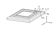
- FIG. 3 is a perspective view of an analysis target
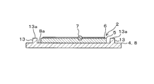
- FIG. 4 is a longitudinal side view
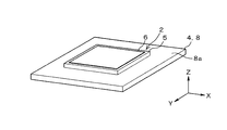
- FIG. 5 is a perspective view of a comparison target
- FIG. 6 is a diagram showing an analysis result of the influence of directivity due to the presence or absence of ribs
- FIG. 7 is a diagram showing analysis results of changes in the half-value angle and the maximum gain depending on the height of the rib
- FIG. 8 is a diagram showing a mode provided on the ceiling of the vehicle
- FIG. 9 is a perspective view showing the overall configuration
- FIG. 10 is a longitudinal side view showing an internal configuration
- FIG. 11 is a perspective view showing the overall configuration of the second embodiment of the present invention
- FIG. 12 is a longitudinal side view.
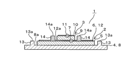
- the antenna device 1 is configured to receive an L1 band (1575.42 MHz) satellite radio wave and an L2 band (1227.6 MHz) satellite radio wave transmitted from a GNSS (Global Navigation Satellite System) satellite.
- the antenna device 1 includes a first antenna 2 that receives satellite radio waves in the L2 band and a second antenna 3 that receives satellite radio waves in the L1 band.
- the first antenna 2 is provided on a flat metal plate 4, and the second antenna 3 is provided on the first antenna 2. That is, the first antenna 2 and the second antenna 3 are stacked.
- the antenna device 1 is mounted on a vehicle such that the stacking direction of the first antenna 2 and the second antenna 3 is the zenith direction.
- the first antenna 2 is a patch antenna, and is a first antenna element made of a rectangular parallelepiped first dielectric 5 having a predetermined dielectric constant and a metal plate provided on the first dielectric 5. 6.
- a power feeding unit 7 is provided at a predetermined portion of the first antenna element 6, and power is fed to the first antenna element 6 through a metal power feeding pin that penetrates the first dielectric 5.
- the first antenna 2 is provided in the central part on the metal plate 4, and the metal plate 4 operates as the first antenna ground plane 8.
- the first antenna 2 is reduced in electrical size due to the wavelength shortening effect due to the dielectric constant of the first dielectric 5.
- the second antenna 3 is a patch antenna similar to the first antenna 2, and has a rectangular parallelepiped second dielectric 9 having a predetermined dielectric constant and a metal provided on the second dielectric 9. And a second antenna element 10 made of a plate.
- a power feeding unit 11 is provided at a predetermined portion of the second antenna element 10, and power is fed to the second antenna element 10 through a metal power feeding pin that penetrates the second dielectric 9.
- the second antenna 3 is provided in the central portion on the first antenna element 6 and operates using the first antenna element 6 as the second antenna ground plane 12.
- the electrical size of the second antenna 3 is also reduced due to the wavelength shortening effect due to the dielectric constant of the second dielectric material 9.
- the dielectric constant of the first dielectric 5 is larger than the dielectric constant of the second dielectric 9. That is, the first antenna 2 having the dielectric 5 having a relatively high dielectric constant is the lower layer, and the second antenna 3 having the dielectric 9 having the relatively low dielectric constant is the upper layer.
- An upper surface portion 8a (corresponding to a flat surface portion) of the first antenna ground plate 8 protrudes from the surface in the stacking direction and surrounds the entire circumference of the first antenna 2 with a predetermined value.
- a frame-shaped first rib 13 is integrally formed with a clearance.
- the first rib 13 has the same potential as the first antenna ground plane 8, and its height is substantially the same as the height of the first dielectric 5. That is, the upper surface portion 13a (corresponding to the same potential portion) of the first rib 13 and the end portion of the first antenna element 6 are close to each other.
- An upper surface portion 12 a (corresponding to a flat surface portion) of the second antenna ground plane 12 protrudes from the surface in the stacking direction and surrounds the entire circumference of the second antenna 3 with a predetermined distance.
- the frame-shaped second rib 14 is integrally formed with a clearance.
- the second rib 14 has the same potential as the second antenna ground plane 12, and its height is substantially the same as the height of the second dielectric 9. That is, the upper surface portion 14a (corresponding to the same potential portion) of the second rib 14 and the end portion of the second antenna element 10 are close to each other.
- the upper surface portion 13a of the first rib 13 and the end portion of the first antenna element 6 are close to each other, whereby the first antenna element 6 and the upper surface portion 13a of the first rib 13 are The electrical coupling between the two increases.
- the electric field generated on the first antenna element 6 is directed in the zenith direction, and the beam is sharpened in the zenith direction.
- the upper surface portion 14a of the second rib 14 and the end portion of the second antenna element 10 are close to each other, the second antenna element 10 and the upper surface portion 14a of the second rib 14 are between.
- Increased electrical coupling As a result, the electric field generated on the second antenna element 10 is directed toward the zenith direction, and the beam is sharpened toward the zenith direction.
- the antenna device in which the second antenna 3 and the second rib 14 are omitted from the configuration shown in FIG. 1 is an analysis target, and as shown in FIG.
- the condition is that the plane size of the first dielectric 5 is 39.5 [mm] ⁇ 39.5 [mm], the height of the first dielectric 5 is 5 [mm], and the first dielectric 5
- the relative permittivity of the body 5 is 12, and the clearance between the first antenna 2 and the first rib 13 is 1 [mm].
- the half-value angle is about 18 [deg] smaller than the configuration in which the first rib 13 is not formed, and the beam is at the zenith. It is sharp in the direction.
- a housing 22 having a shark fin shape is disposed on the ceiling 21 a of the vehicle 21, and the antenna device is disposed inside the housing 22.
- satellite radio waves having a large delay time from the low elevation angle arrive at the satellite radio wave receiving antenna device due to the influence of multipath in which the satellite radio waves are reflected by buildings or roads.
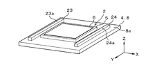
- ribs need not be formed so as to surround the entire circumference of the antenna, It suffices if ribs are formed in two directions facing the antenna. That is, as shown in FIG. 9, in the configuration shown in FIGS. 3 and 4, the rod-shaped ribs 23 and 24 may be provided instead of the frame-shaped first rib 13. In this case, since the upper surface portions 23a and 24a of the ribs 23 and 24 and the end portions of the first antenna element 6 are close to each other, the upper surface portions 23a and 24a of the first antenna element 6 and the ribs 23 and 24 are The electrical coupling between the two increases.
- the electric field generated on the first antenna element 6 is directed in the zenith direction, and the beam is sharpened in the zenith direction.
- the plane part 6a of the 2nd antenna element 6 may become a horizontal direction according to the curved surface of the ceiling part 22a of the vehicle 22. As shown in FIG. good.
- the first rib 13 is provided around the first antenna 2, and the second rib 14 is provided around the second antenna 3.
- the first antenna 2 since the upper surface portion 13 a of the first rib 13 is provided in a portion closer to the upper surface portion 8 a of the antenna ground plane 8 when viewed from the first antenna element 6, the first antenna element 6 And electrical coupling between the upper surface portion 13a of the first rib 13 is enhanced. As a result, the electric field generated on the first antenna element 6 is directed to the zenith direction.
- the upper surface portion 14 a of the second rib 14 is provided at a position closer to the upper surface portion 12 a of the antenna ground plane 12 when viewed from the second antenna element 10. Therefore, electrical coupling is enhanced between the second antenna element 10 and the upper surface portion 14a of the second rib 14. As a result, the electric field generated on the second antenna element 10 is directed to the zenith direction.
- the ribs 13 and 14 are provided on the surfaces of the upper surface portions 8a and 12a of the antenna ground plates 8 and 12, antennas corresponding to a plurality of directional antennas of the conventional configuration are not required, and the antenna ground plate 8 , 12 does not increase in size. Thereby, it is possible to sharpen the beam toward the zenith direction while suppressing an increase in size and cost of the entire apparatus, and it is possible to improve antenna performance.
- the upper second antenna 3 operates using the first antenna element 6 of the lower first antenna 2 as the antenna ground plane 12.
- the configuration Thereby, in the configuration in which a plurality of patch antennas are stacked, each beam can be sharpened toward the zenith direction, and the performance of each antenna can be improved.
- the dielectric constant of the first dielectric 5 of the lower first antenna 2 is larger than the dielectric constant of the second dielectric 9 of the upper second antenna 3.
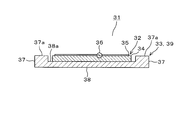
- the antenna device 31 includes an antenna 32 and a metal member 33.
- the antenna 32 has a configuration equivalent to that of the first antenna 2 described in the first embodiment, and includes a rectangular parallelepiped dielectric 34 having a predetermined dielectric constant, and a metal plate provided on the dielectric 34. And an antenna element 35.
- a power feeding portion 36 is provided at a predetermined portion of the antenna element 35, and power is fed to the antenna element 35 via a metal power feeding pin that penetrates the dielectric 34.
- the metal member 33 has a concave shape having an inner portion 38 that is recessed from the outer portion 37.
- the antenna 32 is provided at a central portion on the upper surface portion 38 a (corresponding to a plane portion) of the inner side portion 38, and operates with the metal member 33 as the antenna ground plane 39.
- the height of the outer portion 37 is substantially the same as the height of the dielectric 34. That is, the upper surface portion 37a (corresponding to the same potential portion) of the outer portion 37 and the end portion of the antenna element 35 are close to each other.
- the electrical coupling between the antenna element 35 and the upper surface portion 37 a of the outer portion 37 is enhanced by the proximity of the upper surface portion 37 a of the outer portion 37 and the end portion of the antenna element 35. As a result, the electric field generated on the antenna element 35 is directed in the zenith direction.
- the same operational effects as those of the first embodiment can be obtained. That is, in the antenna 32, the upper surface portion 37 a of the outer portion 37 is provided in a portion closer to the upper surface portion 38 a of the inner portion 38 of the antenna base plate 39 when viewed from the antenna element 35. Electrical coupling with the upper surface portion 37a is enhanced. As a result, the electric field generated on the antenna element 35 can be directed toward the zenith direction, the beam can be sharpened toward the zenith direction, and the antenna performance can be enhanced.
- the structure mounted in a vehicle was illustrated, the structure applied for uses other than a vehicle may be sufficient.
- the configuration in which the first rib 13 is formed integrally with the first antenna ground plate 8 and the second rib 14 is formed integrally with the second antenna ground plate 12 is exemplified.
- the conductive metal member may be retrofitted on the antenna ground plate, and the metal member may be electrically connected to the antenna ground plate.
Landscapes
- Physics & Mathematics (AREA)
- Electromagnetism (AREA)
- Waveguide Aerials (AREA)
- Details Of Aerials (AREA)
- Support Of Aerials (AREA)
- Variable-Direction Aerials And Aerial Arrays (AREA)
Abstract
誘電体(5,9)上に平面形状のアンテナエレメント(6,10)が設けられたパッチアンテナ(2,3)と、平面部(8a,12a)を有するアンテナ地板(8,12)と、を備え、前記パッチアンテナが前記アンテナ地板上に設けられた衛星電波受信用アンテナ装置(1)において、前記アンテナエレメントの周方向の少なくとも一部で且つ前記平面部の面上よりも前記アンテナエレメント側に近い部位に設けられ、前記アンテナ地板と同電位の同電位部(13a,14a)を備える。
Description
本出願は、2015年12月4日に出願された日本出願番号2015-237534号に基づくもので、ここにその記載内容を援用する。
本開示は、衛星電波受信用アンテナ装置に関する。
衛星測位システムを用いて例えば車両等の走行位置を計測する技術が普及している。これに伴って、衛星から送信された衛星電波を受信する衛星電波受信用アンテナ装置が供されている(例えば特許文献1参照)。
例えば車両が走行する環境では衛星電波が建造物や道路等で反射するマルチパスの影響により、低仰角方向からの遅延時間が大きい衛星電波が衛星電波受信用アンテナ装置に到来する。遅延時間が大きい衛星電波は測位性能を低下させる要因となる。そのため、衛星電波受信用アンテナ装置では、低仰角方向から到来する衛星電波の受信を抑えることが望ましく、ビームを天頂方向に向けて鋭くすることが望まれている。この点に関し、特許文献1では、ビームの中心軸を天頂方向に向けた基準となる1つの指向性アンテナと、ビームの中心軸を天頂方向から所定角度ずつずらした複数の指向性アンテナとが設けられる構成を採用している。特許文献1では、複数の指向性アンテナが設けられる構成であるので、アンテナ地板のサイズが大きくなり、装置全体が大型化すると共に、コスト高になるという問題がある。
本開示は、装置全体の大型化やコスト高を抑えつつ、ビームを天頂方向に向けて鋭くすることができ、アンテナ性能を高めることができる衛星電波受信用アンテナ装置を提供することにある。
本開示の一態様によれば、誘電体上に平面形状のアンテナエレメントが設けられたパッチアンテナと、平面部を有するアンテナ地板とを備え、パッチアンテナがアンテナ地板上に設けられている。アンテナエレメントの周方向の少なくとも一部で且つ平面部の面上よりもアンテナエレメント側に近い部位に設けられ、アンテナ地板と同電位の同電位部を備える。
アンテナエレメントから見てアンテナ地板の平面部よりも近い部位に同電位部が設けられているので、アンテナエレメントと同電位部との間で電気的な結合が高まり、アンテナエレメント上に発生する電界が天頂方向に向く。この場合、アンテナ地板の平面部の面上に同電位部が設けられるので、従来構成の複数の指向性アンテナに相当するアンテナが必要となることがなく、アンテナ地板のサイズが大きくなることもない。これにより、装置全体の大型化やコスト高を抑えつつ、ビームを天頂方向に向けて鋭くすることができ、アンテナ性能を高めることができる。
本開示についての上記目的及びその他の目的、特徴や利点は、添付の図面を参照しながら下記の詳細な記述により、より明確になる。その図面は、
図1は、第1の実施形態の全体構成を示す斜視図であり、
図2は、縦断側面図であり、
図3は、解析対象の斜視図であり、
図4は、縦断側面図であり、
図5は、比較対象の斜視図であり、
図6は、リブの有無による指向性の影響の解析結果を示す図であり、
図7は、リブの高さによる半値角及び最大利得の変化の解析結果を示す図であり、
図8は、車両の天井部に設けられた態様を示す図であり、
図9は、全体構成を示す斜視図であり、
図10は、内部の構成を示す縦断側面図であり、
図11は、本発明の第2の実施形態の全体構成を示す斜視図であり、
図12は、縦断側面図である。
(第1の実施形態)
以下、本実施形態に係る衛星電波受信用アンテナ装置(以下、アンテナ装置と称する)の第1の実施形態について図1から図10を参照して説明する。アンテナ装置1は、GNSS(Global Navigation Satellite System)の衛星から送信されるL1帯(1575.42MHz)の衛星電波とL2帯(1227.6MHz)の衛星電波とを受信可能な構成である。アンテナ装置1は、L2帯の衛星電波を受信する第1のアンテナ2と、L1帯の衛星電波を受信する第2のアンテナ3とを有する。第1のアンテナ2は平板形状の金属板4上に設けられており、第2のアンテナ3は第1のアンテナ2上に設けられている。即ち、第1のアンテナ2と第2のアンテナ3とは積層されている。尚、アンテナ装置1は、後述するように第1のアンテナ2と第2のアンテナ3との積層方向が天頂方向となるように車両に搭載される。
以下、本実施形態に係る衛星電波受信用アンテナ装置(以下、アンテナ装置と称する)の第1の実施形態について図1から図10を参照して説明する。アンテナ装置1は、GNSS(Global Navigation Satellite System)の衛星から送信されるL1帯(1575.42MHz)の衛星電波とL2帯(1227.6MHz)の衛星電波とを受信可能な構成である。アンテナ装置1は、L2帯の衛星電波を受信する第1のアンテナ2と、L1帯の衛星電波を受信する第2のアンテナ3とを有する。第1のアンテナ2は平板形状の金属板4上に設けられており、第2のアンテナ3は第1のアンテナ2上に設けられている。即ち、第1のアンテナ2と第2のアンテナ3とは積層されている。尚、アンテナ装置1は、後述するように第1のアンテナ2と第2のアンテナ3との積層方向が天頂方向となるように車両に搭載される。
第1のアンテナ2は、パッチアンテナであり、所定の誘電率を有する直方体形状の第1の誘電体5と、第1の誘電体5上に設けられている金属板からなる第1のアンテナエレメント6とを有する。第1のアンテナエレメント6の所定部位には給電部7が設けられており、第1の誘電体5を貫通する金属製の給電ピンを介して第1のアンテナエレメント6に給電される。第1のアンテナ2は、金属板4上の中央部に設けられており、金属板4を第1のアンテナ地板8として動作する。尚、第1のアンテナ2は、第1の誘電体5の誘電率による波長短縮効果により、電気的なサイズが縮小されている。
第2のアンテナ3は、第1のアンテナ2と同様にパッチアンテナであり、所定の誘電率を有する直方体形状の第2の誘電体9と、第2の誘電体9上に設けられている金属板からなる第2のアンテナエレメント10とを有する。第2のアンテナエレメント10の所定部位には給電部11が設けられており、第2の誘電体9を貫通する金属製の給電ピンを介して第2のアンテナエレメント10に給電される。第2のアンテナ3は、第1のアンテナエレメント6上の中央部に設けられており、第1のアンテナエレメント6を第2のアンテナ地板12として動作する。尚、第2のアンテナ3も、第2の誘電体9の誘電率による波長短縮効果により、電気的なサイズが縮小されている。又、上記した第1の誘電体5の誘電率は第2の誘電体9の誘電率よりも大きい。即ち、誘電率が相対的に大きい誘電体5を有する第1のアンテナ2が下層であり、誘電率が相対的に小さい誘電体9を有する第2のアンテナ3が上層である。
第1のアンテナ地板8の上面部8a(平面部に相当する)には、その面上から積層方向に突出し且つ第1のアンテナ2の全周を囲むように当該第1のアンテナ2と所定のクリアランスを存して枠形状の第1のリブ13が一体的に形成されている。第1のリブ13は、第1のアンテナ地板8と同電位であり、その高さは第1の誘電体5の高さと略同じである。即ち、第1のリブ13の上面部13a(同電位部に相当する)と第1のアンテナエレメント6の端部とは近接している。第2のアンテナ地板12の上面部12a(平面部に相当する)には、その面上から積層方向に突出し且つ第2のアンテナ3の全周を囲むように当該第2のアンテナ3と所定のクリアランスを存して枠形状の第2のリブ14が一体的に形成されている。第2のリブ14は、第2のアンテナ地板12と同電位であり、その高さは第2の誘電体9の高さと略同じである。即ち、第2のリブ14の上面部14a(同電位部に相当する)と第2のアンテナエレメント10の端部とは近接している。
上記した構成では、第1のリブ13の上面部13aと第1のアンテナエレメント6の端部とが近接していることにより、第1のアンテナエレメント6と第1のリブ13の上面部13aとの間で電気的な結合が高まる。その結果、第1のアンテナエレメント6上に発生する電界が天頂方向に向き、ビームが天頂方向に向けて鋭くなる。又、第2のリブ14の上面部14aと第2のアンテナエレメント10の端部とが近接していることにより、第2のアンテナエレメント10と第2のリブ14の上面部14aとの間で電気的な結合が高まる。その結果、第2のアンテナエレメント10上に発生する電界が天頂方向に向き、ビームが天頂方向に向けて鋭くなる。
ここで、第1のリブ13や第2のリブ14の有無による指向性の影響について説明する。図3及び図4に示すように、図1に示した構成から第2のアンテナ3及び第2のリブ14を省いたアンテナ装置を解析対象とすると共に、図5に示すように、図3及び図4に示した構成から第1のリブ13を省いたアンテナ装置を比較対象とする。尚、条件としては、第1の誘電体5の平面のサイズを39.5[mm]×39.5[mm]、第1の誘電体5の高さを5[mm]、第1の誘電体5の比誘電率を12、第1のアンテナ2と第1のリブ13とのクリアランスを1[mm]としている。図6に示すように、第1のリブ13が形成されている構成では、第1のリブ13が形成されていない構成に対して半値角が約18[deg]小さくなっており、ビームが天頂方向に向かって鋭くなっている。
次に、第1のリブ13や第2のリブ14の高さによる半値角及び最大利得の変化について説明する。図7に示すように、前述した図3及び図4に示した構成を解析対象とする。図7に示すように、リブの高さが高くなるにしたがって半値角が低下すると共に最大利得が低下している。
次に、アンテナ装置が車両に搭載される態様について説明する。アンテナ装置が車両に搭載される場合、図8に示すように、車両21の天井部21aにシャークフィンの形状をなす筐体22が配置され、その筐体22の内部にアンテナ装置が配置される。この場合、車両22が走行する環境では衛星電波が建造物や道路等で反射するマルチパスの影響により、低仰角方向からの遅延時間が大きい衛星電波が衛星電波受信用アンテナ装置に到来する。特に、車両22の左右方向の低仰角方向からよりも車両22の前後方向の低仰角方向から到来する衛星電波が多いので、アンテナの全周を囲むようにリブが形成されている必要はなく、アンテナの対向する2方向でリブが形成されていれば良い。即ち、図9に示すように、前述した図3及び図4に示した構成において枠形状の第1のリブ13に代えて、棒形状のリブ23,24が設けられている構成でも良い。この場合、リブ23,24の上面部23a,24aと第1のアンテナエレメント6の端部とが近接していることにより、第1のアンテナエレメント6とリブ23,24の上面部23a,24aとの間で電気的な結合が高まる。その結果、この場合も、第1のアンテナエレメント6上に発生する電界が天頂方向に向き、ビームが天頂方向に向けて鋭くなる。尚、図10に示すように、車両22の天井部22aの曲面に合わせて第2のアンテナエレメント6の平面部6aが水平方向となるように基板25上に台座26を介して設けられても良い。
以上に説明したように第1の実施形態によれば、次に示す効果を得ることができる。
アンテナ装置1において、第1のアンテナ2の周囲に第1のリブ13が設けられ、第2のアンテナ3の周囲に第2のリブ14が設けられる構成とした。第1のアンテナ2では、第1のアンテナエレメント6から見てアンテナ地板8の上面部8aよりも近い部位に第1のリブ13の上面部13aが設けられているので、第1のアンテナエレメント6と第1のリブ13の上面部13aとの間で電気的な結合が高まる。その結果、第1のアンテナエレメント6上に発生する電界が天頂方向に向く。又、第2のアンテナ3でも、第1のアンテナ2と同様に、第2のアンテナエレメント10から見てアンテナ地板12の上面部12aよりも近い部位に第2のリブ14の上面部14aが設けられているので、第2のアンテナエレメント10と第2のリブ14の上面部14aとの間で電気的な結合が高まる。その結果、第2のアンテナエレメント10上に発生する電界が天頂方向に向く。この場合、アンテナ地板8,12の上面部8a,12aの面上にリブ13,14が設けられるので、従来構成の複数の指向性アンテナに相当するアンテナが必要となることがなく、アンテナ地板8,12のサイズが大きくなることもない。これにより、装置全体の大型化やコスト高を抑えつつ、ビームを天頂方向に向けて鋭くすることができ、アンテナ性能を高めることができる。
アンテナ装置1において、第1のアンテナ2の周囲に第1のリブ13が設けられ、第2のアンテナ3の周囲に第2のリブ14が設けられる構成とした。第1のアンテナ2では、第1のアンテナエレメント6から見てアンテナ地板8の上面部8aよりも近い部位に第1のリブ13の上面部13aが設けられているので、第1のアンテナエレメント6と第1のリブ13の上面部13aとの間で電気的な結合が高まる。その結果、第1のアンテナエレメント6上に発生する電界が天頂方向に向く。又、第2のアンテナ3でも、第1のアンテナ2と同様に、第2のアンテナエレメント10から見てアンテナ地板12の上面部12aよりも近い部位に第2のリブ14の上面部14aが設けられているので、第2のアンテナエレメント10と第2のリブ14の上面部14aとの間で電気的な結合が高まる。その結果、第2のアンテナエレメント10上に発生する電界が天頂方向に向く。この場合、アンテナ地板8,12の上面部8a,12aの面上にリブ13,14が設けられるので、従来構成の複数の指向性アンテナに相当するアンテナが必要となることがなく、アンテナ地板8,12のサイズが大きくなることもない。これにより、装置全体の大型化やコスト高を抑えつつ、ビームを天頂方向に向けて鋭くすることができ、アンテナ性能を高めることができる。
又、第1のアンテナ2と第2のアンテナ3とが積層される構成において、上層の第2のアンテナ3が下層の第1のアンテナ2の第1のアンテナエレメント6をアンテナ地板12として動作する構成とした。これにより、複数のパッチアンテナを積層する構成において、それぞれのビームを天頂方向に向けて鋭くすることができ、それぞれのアンテナ性能を高めることができる。又、下層の第1のアンテナ2の第1の誘電体5の誘電率が上層の第2のアンテナ3の第2の誘電体9の誘電率よりも大きい構成とした。これにより、複数のパッチアンテナを積層する構成において、波長短縮効果をより一層高めることができ、装置全体の小型化を図ることができる。
(第2の実施形態)
次に、本発明の第2の実施形態について図11及び図12を参照して説明する。尚、前述した第1の実施形態と同一部分については説明を省略し、異なる部分について説明する。第2の実施形態において、アンテナ装置31は、アンテナ32と、金属部材33とを有する。アンテナ32は、第1の実施形態で説明した第1のアンテナ2と同等の構成であり、所定の誘電率を有する直方体形状の誘電体34と、誘電体34上に設けられている金属板からなるアンテナエレメント35とを有する。アンテナエレメント35の所定部位には給電部36が設けられており、誘電体34を貫通する金属製の給電ピンを介してアンテナエレメント35に給電される。
次に、本発明の第2の実施形態について図11及び図12を参照して説明する。尚、前述した第1の実施形態と同一部分については説明を省略し、異なる部分について説明する。第2の実施形態において、アンテナ装置31は、アンテナ32と、金属部材33とを有する。アンテナ32は、第1の実施形態で説明した第1のアンテナ2と同等の構成であり、所定の誘電率を有する直方体形状の誘電体34と、誘電体34上に設けられている金属板からなるアンテナエレメント35とを有する。アンテナエレメント35の所定部位には給電部36が設けられており、誘電体34を貫通する金属製の給電ピンを介してアンテナエレメント35に給電される。
金属部材33は、外側部37から凹んだ内側部38を有する凹形状により構成されている。アンテナ32は、内側部38の上面部38a(平面部に相当する)上の中央部に設けられており、金属部材33をアンテナ地板39として動作する。外側部37は、その高さが誘電体34の高さと略同じである。即ち、外側部37の上面部37a(同電位部に相当する)とアンテナエレメント35の端部とは近接している。上記した構成では、外側部37の上面部37aとアンテナエレメント35の端部とが近接していることにより、アンテナエレメント35と外側部37の上面部37aとの間で電気的な結合が高まる。その結果、アンテナエレメント35上に発生する電界が天頂方向に向く。
以上に説明したように第2の実施形態によれば、第1の実施形態と同様の作用効果を得ることができる。即ち、アンテナ32では、アンテナエレメント35から見てアンテナ地板39の内側部38の上面部38aよりも近い部位に外側部37の上面部37aが設けられているので、アンテナエレメント35と外側部37の上面部37aとの間で電気的な結合が高まる。その結果、アンテナエレメント35上に発生する電界が天頂方向に向き、ビームを天頂方向に向けて鋭くすることができ、アンテナ性能を高めることができる。
(その他の実施形態)
本開示は、実施形態に準拠して記述されたが、当該実施形態や構造に限定されるものではないと理解される。本開示は、様々な変形例や均等範囲内の変形をも包含する。加えて、様々な組み合わせや形態、更には、それらに一要素のみ、それ以上、或いはそれ以下、を含む他の組み合わせや形態をも、本開示の範疇や思想範囲に入るものである。
本開示は、実施形態に準拠して記述されたが、当該実施形態や構造に限定されるものではないと理解される。本開示は、様々な変形例や均等範囲内の変形をも包含する。加えて、様々な組み合わせや形態、更には、それらに一要素のみ、それ以上、或いはそれ以下、を含む他の組み合わせや形態をも、本開示の範疇や思想範囲に入るものである。
車両に搭載される構成を例示したが、車両以外の用途で適用される構成でも良い。
第1の実施形態では、第1のリブ13が第1のアンテナ地板8に一体的に形成され、第2のリブ14が第2のアンテナ地板12に一体的に形成された構成を例示したが、導電性の金属部材がアンテナ地板上に後付けで設けられ、その金属部材がアンテナ地板と電気的に接続された構成でも良い。
第1の実施形態では、第1のリブ13が第1のアンテナ地板8に一体的に形成され、第2のリブ14が第2のアンテナ地板12に一体的に形成された構成を例示したが、導電性の金属部材がアンテナ地板上に後付けで設けられ、その金属部材がアンテナ地板と電気的に接続された構成でも良い。
第1の実施形態では、2個のパッチアンテナが積層された構成を例示したが、3個以上のパッチアンテナが積層された構成でも良い。
Claims (7)
- 誘電体(5,9,34)上に平面形状のアンテナエレメント(6,10,35)が設けられたパッチアンテナ(2,3,32)と、平面部(8a,12a,38a)を有するアンテナ地板(8,12,39)と、を備え、前記パッチアンテナが前記アンテナ地板上に設けられた衛星電波受信用アンテナ装置(1,31)において、
前記アンテナエレメントの周方向の少なくとも一部で且つ前記平面部の面上よりも前記アンテナエレメント側に近い部位に設けられ、前記アンテナ地板と同電位の同電位部(13a,14a,23a,24a,37a)を備えた衛星電波受信用アンテナ装置。 - 前記パッチアンテナと前記アンテナ地板との組が複数であり、前記複数のパッチアンテナが積層され、
上層の前記パッチアンテナ(3)は、下層の前記パッチアンテナ(2)の前記アンテナエレメント(6)をアンテナ地板(12)として動作する請求項1に記載の衛星電波受信用アンテナ装置。 - 下層の前記パッチアンテナの前記誘電体の誘電率は上層の前記パッチアンテナの前記誘電体の誘電率よりも大きい請求項2に記載の衛星電波受信用アンテナ装置。
- 前記同電位部(13a,14a,37a)は、前記アンテナエレメントの全周に亘って設けられている請求項1から3の何れか一項に記載の衛星電波受信用アンテナ装置。
- 車両に搭載可能に構成され、
前記同電位部(23a,24a)は、車両に搭載された状態で当該車両の前後方向となる前記アンテナエレメントの周方向の対向する部位に設けられている請求項1から3の何れか一項に記載の衛星電波受信用アンテナ装置。 - 前記アンテナ地板は、前記平面部(8a,12a)を有する平面形状により構成され、
前記同電位部(13a,14a,23a,24a)は、前記平面部の面上から突出したリブ(13,14,23,24)の上面部により構成されている請求項4又は5に記載の衛星電波受信用アンテナ装置(1)。 - 前記アンテナ地板は、外側部(37)から凹んだ内側部(38)に前記平面部(38a)を有する凹形状により構成され、
前記同電位部(37a)は、前記外側部の上面部により構成されている請求項5に記載の衛星電波受信用アンテナ装置(31)。
Applications Claiming Priority (2)
| Application Number | Priority Date | Filing Date | Title |
|---|---|---|---|
| JP2015237534A JP6405297B2 (ja) | 2015-12-04 | 2015-12-04 | 衛星電波受信用アンテナ装置 |
| JP2015-237534 | 2015-12-04 |
Publications (1)
| Publication Number | Publication Date |
|---|---|
| WO2017094441A1 true WO2017094441A1 (ja) | 2017-06-08 |
Family
ID=58797052
Family Applications (1)
| Application Number | Title | Priority Date | Filing Date |
|---|---|---|---|
| PCT/JP2016/082819 Ceased WO2017094441A1 (ja) | 2015-12-04 | 2016-11-04 | 衛星電波受信用アンテナ装置 |
Country Status (2)
| Country | Link |
|---|---|
| JP (1) | JP6405297B2 (ja) |
| WO (1) | WO2017094441A1 (ja) |
Cited By (1)
| Publication number | Priority date | Publication date | Assignee | Title |
|---|---|---|---|---|
| CN112368889A (zh) * | 2018-07-05 | 2021-02-12 | 株式会社电装 | 天线装置 |
Families Citing this family (2)
| Publication number | Priority date | Publication date | Assignee | Title |
|---|---|---|---|---|
| JP7663167B2 (ja) | 2023-09-15 | 2025-04-16 | エヌ・ティ・ティ・コミュニケーションズ株式会社 | 衛星測位受信機 |
| JP7616581B1 (ja) | 2023-09-15 | 2025-01-17 | エヌ・ティ・ティ・コミュニケーションズ株式会社 | 衛星測位受信機 |
Citations (5)
| Publication number | Priority date | Publication date | Assignee | Title |
|---|---|---|---|---|
| JPS6395309U (ja) * | 1986-12-11 | 1988-06-20 | ||
| JPS63169103A (ja) * | 1986-12-23 | 1988-07-13 | ボール、コーパレイシヤン | 無線周波アンテナ |
| JP2001053534A (ja) * | 1999-08-16 | 2001-02-23 | Tdk Corp | マイクロストリップアンテナ |
| US20030122718A1 (en) * | 2001-12-27 | 2003-07-03 | Shyh-Tirng Fang | Dual-frequency planar antenna |
| JP2010525742A (ja) * | 2007-04-23 | 2010-07-22 | アルカテル−ルーセント ユーエスエー インコーポレーテッド | ストリップ・アレー・アンテナ |
Family Cites Families (5)
| Publication number | Priority date | Publication date | Assignee | Title |
|---|---|---|---|---|
| JP2961862B2 (ja) * | 1990-10-04 | 1999-10-12 | ソニー株式会社 | 平面アンテナ |
| JP3020777B2 (ja) * | 1993-07-23 | 2000-03-15 | 宏之 新井 | 二周波共用アンテナ |
| JP2004015740A (ja) * | 2002-06-11 | 2004-01-15 | Mitsubishi Electric Corp | アンテナ装置 |
| JP2004096259A (ja) * | 2002-08-30 | 2004-03-25 | Matsushita Electric Ind Co Ltd | 多周波マイクロストリップアンテナ |
| JP2007097115A (ja) * | 2005-02-25 | 2007-04-12 | Tdk Corp | パッチアンテナ |
-
2015
- 2015-12-04 JP JP2015237534A patent/JP6405297B2/ja not_active Expired - Fee Related
-
2016
- 2016-11-04 WO PCT/JP2016/082819 patent/WO2017094441A1/ja not_active Ceased
Patent Citations (5)
| Publication number | Priority date | Publication date | Assignee | Title |
|---|---|---|---|---|
| JPS6395309U (ja) * | 1986-12-11 | 1988-06-20 | ||
| JPS63169103A (ja) * | 1986-12-23 | 1988-07-13 | ボール、コーパレイシヤン | 無線周波アンテナ |
| JP2001053534A (ja) * | 1999-08-16 | 2001-02-23 | Tdk Corp | マイクロストリップアンテナ |
| US20030122718A1 (en) * | 2001-12-27 | 2003-07-03 | Shyh-Tirng Fang | Dual-frequency planar antenna |
| JP2010525742A (ja) * | 2007-04-23 | 2010-07-22 | アルカテル−ルーセント ユーエスエー インコーポレーテッド | ストリップ・アレー・アンテナ |
Cited By (1)
| Publication number | Priority date | Publication date | Assignee | Title |
|---|---|---|---|---|
| CN112368889A (zh) * | 2018-07-05 | 2021-02-12 | 株式会社电装 | 天线装置 |
Also Published As
| Publication number | Publication date |
|---|---|
| JP2017103709A (ja) | 2017-06-08 |
| JP6405297B2 (ja) | 2018-10-17 |
Similar Documents
| Publication | Publication Date | Title |
|---|---|---|
| US10680318B2 (en) | Antenna apparatus | |
| JP5789492B2 (ja) | マイクロ波アンテナ | |
| US10074895B2 (en) | Collective antenna device | |
| JP7168752B2 (ja) | スロット付きパッチアンテナ | |
| CN105990681B (zh) | 一种天线及机载通信设备 | |
| CN106169652A (zh) | 天线装置、无线通信装置及雷达装置 | |
| US11201409B2 (en) | Patch antenna and antenna device | |
| US9257748B1 (en) | Broadband, low-profile antenna structure | |
| JP2011223342A (ja) | レドーム、アンテナ装置、およびレーダ装置 | |
| US11152691B2 (en) | Dual broadband antenna system for vehicles | |
| JP2022066544A (ja) | アンテナ装置 | |
| JP6405297B2 (ja) | 衛星電波受信用アンテナ装置 | |
| CN110419144A (zh) | 天线单元及天线阵列 | |
| JP2016152590A (ja) | アンテナユニット | |
| KR20130052176A (ko) | 원형 편파 및 선형 편파 수신을 위한 패치 안테나 | |
| JP5837452B2 (ja) | アンテナ装置 | |
| US8228237B2 (en) | Antenna with double groundings | |
| JP2013197682A (ja) | アンテナ装置 | |
| TWI538299B (zh) | Broadband circularly polarized monopole antenna | |
| JP7040951B2 (ja) | アンテナ装置 | |
| US20240283142A1 (en) | Vehicular antenna device | |
| JP6909766B2 (ja) | アンテナ装置 | |
| JP5774641B2 (ja) | ループアンテナ | |
| US20190326673A1 (en) | Dual Small Antennas with Feed Points Fed Out of Phase | |
| TWM561930U (zh) | 圓極化天線構造 |
Legal Events
| Date | Code | Title | Description |
|---|---|---|---|
| 121 | Ep: the epo has been informed by wipo that ep was designated in this application |
Ref document number: 16870381 Country of ref document: EP Kind code of ref document: A1 |
|
| NENP | Non-entry into the national phase |
Ref country code: DE |
|
| 122 | Ep: pct application non-entry in european phase |
Ref document number: 16870381 Country of ref document: EP Kind code of ref document: A1 |