WO2017090335A1 - 照明構造 - Google Patents
照明構造 Download PDFInfo
- Publication number
- WO2017090335A1 WO2017090335A1 PCT/JP2016/080475 JP2016080475W WO2017090335A1 WO 2017090335 A1 WO2017090335 A1 WO 2017090335A1 JP 2016080475 W JP2016080475 W JP 2016080475W WO 2017090335 A1 WO2017090335 A1 WO 2017090335A1
- Authority
- WO
- WIPO (PCT)
- Prior art keywords
- reflector
- light source
- reflection
- light
- wall
- Prior art date
- Legal status (The legal status is an assumption and is not a legal conclusion. Google has not performed a legal analysis and makes no representation as to the accuracy of the status listed.)
- Ceased
Links
Images


Classifications
-
- G—PHYSICS
- G02—OPTICS
- G02B—OPTICAL ELEMENTS, SYSTEMS OR APPARATUS
- G02B27/00—Optical systems or apparatus not provided for by any of the groups G02B1/00 - G02B26/00, G02B30/00
- G02B27/01—Head-up displays
- G02B27/0101—Head-up displays characterised by optical features
-
- F—MECHANICAL ENGINEERING; LIGHTING; HEATING; WEAPONS; BLASTING
- F21—LIGHTING
- F21V—FUNCTIONAL FEATURES OR DETAILS OF LIGHTING DEVICES OR SYSTEMS THEREOF; STRUCTURAL COMBINATIONS OF LIGHTING DEVICES WITH OTHER ARTICLES, NOT OTHERWISE PROVIDED FOR
- F21V7/00—Reflectors for light sources
- F21V7/0083—Array of reflectors for a cluster of light sources, e.g. arrangement of multiple light sources in one plane
-
- F—MECHANICAL ENGINEERING; LIGHTING; HEATING; WEAPONS; BLASTING
- F21—LIGHTING
- F21V—FUNCTIONAL FEATURES OR DETAILS OF LIGHTING DEVICES OR SYSTEMS THEREOF; STRUCTURAL COMBINATIONS OF LIGHTING DEVICES WITH OTHER ARTICLES, NOT OTHERWISE PROVIDED FOR
- F21V7/00—Reflectors for light sources
- F21V7/04—Optical design
- F21V7/041—Optical design with conical or pyramidal surface
-
- F—MECHANICAL ENGINEERING; LIGHTING; HEATING; WEAPONS; BLASTING
- F21—LIGHTING
- F21V—FUNCTIONAL FEATURES OR DETAILS OF LIGHTING DEVICES OR SYSTEMS THEREOF; STRUCTURAL COMBINATIONS OF LIGHTING DEVICES WITH OTHER ARTICLES, NOT OTHERWISE PROVIDED FOR
- F21V7/00—Reflectors for light sources
- F21V7/04—Optical design
- F21V7/09—Optical design with a combination of different curvatures
-
- G—PHYSICS
- G02—OPTICS
- G02B—OPTICAL ELEMENTS, SYSTEMS OR APPARATUS
- G02B19/00—Condensers, e.g. light collectors or similar non-imaging optics
- G02B19/0004—Condensers, e.g. light collectors or similar non-imaging optics characterised by the optical means employed
- G02B19/0019—Condensers, e.g. light collectors or similar non-imaging optics characterised by the optical means employed having reflective surfaces only (e.g. louvre systems, systems with multiple planar reflectors)
-
- G—PHYSICS
- G02—OPTICS
- G02B—OPTICAL ELEMENTS, SYSTEMS OR APPARATUS
- G02B19/00—Condensers, e.g. light collectors or similar non-imaging optics
- G02B19/0033—Condensers, e.g. light collectors or similar non-imaging optics characterised by the use
- G02B19/0047—Condensers, e.g. light collectors or similar non-imaging optics characterised by the use for use with a light source
- G02B19/0061—Condensers, e.g. light collectors or similar non-imaging optics characterised by the use for use with a light source the light source comprising a LED
-
- F—MECHANICAL ENGINEERING; LIGHTING; HEATING; WEAPONS; BLASTING
- F21—LIGHTING
- F21Y—INDEXING SCHEME ASSOCIATED WITH SUBCLASSES F21K, F21L, F21S and F21V, RELATING TO THE FORM OR THE KIND OF THE LIGHT SOURCES OR OF THE COLOUR OF THE LIGHT EMITTED
- F21Y2115/00—Light-generating elements of semiconductor light sources
- F21Y2115/10—Light-emitting diodes [LED]
-
- G—PHYSICS
- G02—OPTICS
- G02B—OPTICAL ELEMENTS, SYSTEMS OR APPARATUS
- G02B27/00—Optical systems or apparatus not provided for by any of the groups G02B1/00 - G02B26/00, G02B30/00
- G02B27/01—Head-up displays
- G02B27/0101—Head-up displays characterised by optical features
- G02B2027/0118—Head-up displays characterised by optical features comprising devices for improving the contrast of the display / brillance control visibility
Definitions
- This case relates to the lighting structure.
- Some display devices include an illumination device such as a backlight capable of illuminating a display unit.
- the backlight described in Patent Document 1 includes a circuit board having a light source (LED) attached to the surface thereof, and a reflector (reflecting member) disposed on the surface side of the circuit board so as to surround the light source. And have.
- LED light source
- reflector reflecting member
- the main purpose of this case is to solve the above-mentioned problems.
- a circuit board having a light source attached to the surface;
- a reflector disposed on the surface side of the circuit board so as to surround the light source;
- the reflector has a pyramidal reflection wall,
- the illumination structure is characterized in that four inner surfaces of the pyramidal reflection wall portion are steep slope portions having an angle larger than 7.5 degrees and smaller than 15 degrees with respect to the direction of the optical axis of the light source. .
- the illumination efficiency can be increased by the above configuration.
- FIG. 4 is a front view of FIG. 3. It is sectional drawing which cut
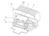
- the display device 1 includes a display unit 2 and a backlight 3 (illumination device) that illuminates the display unit 2 from the back side, and is displayed by the backlight 3. It is assumed that the part 2 can be illuminated.
- the backlight 3 described above includes a circuit board 6 having a light source 5 attached to the surface thereof, as shown in FIGS.
- a reflector 7 is provided on the surface side of the circuit board 6 so as to surround the light source 5.
- an LED or the like is used for the light source 5.
- a general LED having an irradiation angle that extends to about 60 degrees on one side (120 degrees on both sides) with respect to the optical axis 8 is used.
- the light emitting portion has a substantially square shape in plan view.
- a heat sink 11 having heat dissipating fins 11a is attached to the back side of the circuit board 6 (see FIG. 2).
- the heat sink 11 is made of a metal having good thermal conductivity such as aluminum.
- the reflector 7 is a light guide component having a substantially cylindrical or frame shape.
- the reflector 7 has a board contact portion 12 that is in contact with the circuit board 6 on the base side (back side).
- the reflector 7 has the light emission part 13 which radiate
- the reflector 7 directly surrounds the light source 5 and reflects the light 14 from the light source 5 toward the light output portion 13, and an outer peripheral wall surrounding the outside of the reflection wall portion 15.
- the resin part has a double structure having a portion 16.
- the inner surface of the reflecting wall 15 is a reflecting surface.
- the reflection wall part 15 and the outer peripheral wall part 16 are integrally connected by the frame-shaped connection surface part 18 in the front end part.
- An inner portion (opening) of the frame-shaped connecting surface portion 18 is the light emitting portion 13, and the light emitting portion 13 is continuous with the inner surface of the reflecting wall portion 15.
- the inside of the reflection wall portion 15 is a lamp chamber 21 (illumination room) that houses the light source 5, and the enclosure that surrounds the outside of the lamp chamber 21 is between the reflection wall portion 15 and the outer peripheral wall portion 16.
- a space 22 is provided.
- the light emitting section 13 is approximately the same size as the illumination area of the light source 5 with respect to the display section 2.
- the display device 1 can illuminate the display unit 2 by disposing the backlight 3 so that the light output unit 13 faces the back side of the display unit 2 with respect to the display device 1.
- the display unit 2 can be, for example, a dial or a liquid crystal panel.
- the display device 1 using the display unit 2 as a dial can be an instrument device or the like.
- the display device 1 in which the display unit 2 is a liquid crystal panel can be a liquid crystal display device or the like.
- the display unit 2 can be a combination of a dial and a liquid crystal panel.
- the illumination structure of this embodiment has the following configuration.
- the reflector 7 is assumed to have a pyramidal reflecting wall 15 (see FIG. 4). Then, the four inner surfaces of the pyramidal reflection wall portion 15 are steep slope portions 33 having an angle 32 that can alleviate / suppress luminance unevenness while ensuring the maximum luminance 31 (see FIG. 7) of the light source 5. Specifically, the steep slope 33 has an angle 32 that is greater than 7.5 degrees and smaller than 15 degrees with respect to the direction of the optical axis 8 of the light source 5.
- the pyramid shape is a square pyramid having a square cross section.
- the reflecting wall 15 (inner surface) into a pyramid shape, the reflecting wall 15 has a planar shape similar to the light emitting portion of the light source 5 having a square shape in plan view.
- the pyramidal reflecting wall 15 is installed so as to be concentric with the center of the light emitting part of the light source 5 and to have each side parallel to each other.
- the base portion of the reflecting wall portion 15 is a rectangular shape that is slightly larger than the light emitting portion of the light source 5 so as not to interfere with the light emitting portion of the light source 5.
- the maximum luminance 31 of the light source 5 is the maximum luminance obtained by condensing the light 14 from the light source 5. However, the maximum luminance 31 can be allowed as long as the luminance is reduced to about less than 5%.
- the luminance unevenness is a state in which the luminance difference between the bright part and the dark part is large. The luminance unevenness is determined by whether or not it can be recognized by human vision. In terms of experience, when the luminance difference between the central portion (bright portion) and the peripheral portion (dark portion) is doubled or more, luminance unevenness is recognized by many people.
- the steep slope is an angle smaller than 45 degrees with respect to the direction of the optical axis 8.
- the gentle slope is an angle larger than 45 degrees with respect to the direction of the optical axis 8.
- the reflecting wall 15 for the light 14 from the light source 5 that passes directly without being reflected by the inner surface of the reflecting wall 15 of the reflector 7 (direct light). Since the ratio of the reflected light (reflected light) is increased, the light collection effect is increased and high luminance can be obtained. On the other hand, the four inner surfaces of the reflection wall portion 15 are made gentle slopes. Then, since the ratio of the reflected light to the direct light is reduced, the light condensing effect is lowered, and only low luminance tends to be obtained.
- the brightness difference between the central portion and the peripheral portion increases as the angle 32 of the inner surface decreases, as in the case where the four inner surfaces of the reflecting wall 15 are steeply inclined to increase the light collecting effect.
- the angle 32 of the inner surface increases as in the case where the four inner surfaces of the reflecting wall 15 are made gentle slopes to reduce the light collecting effect, etc. (see point A1 in FIG. 7).
- the luminance difference between the central portion (bright portion) and the peripheral portion (dark portion) is reduced and the luminance unevenness is reduced (see points A2 and A5 in FIG. 7). It looks different from the time of color due to black and white).
- the improvement in luminance and the reduction in luminance unevenness are phenomena obtained by conflicting configurations. If the angle 32 on the inner surface of the reflecting wall 15 where the balance between the two is the best is known, the illumination efficiency becomes the highest.
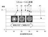
- FIG. 7 summarizes the simulation results.
- the angle 32 of the reflecting wall portion 15 is 15 degrees (7.5 degrees on one side with respect to the direction of the optical axis 8, point A1), 20 degrees (10 degrees on one side with respect to the direction of the optical axis 8, and points) A2), 25 degrees (12.5 degrees on one side with respect to the direction of the optical axis 8 and point A3), the maximum luminance 31 was obtained.
- the angle 32 of the reflecting wall 15 is 28 degrees (14 degrees on one side with respect to the direction of the optical axis 8, point A4), 30 degrees (15 degrees on one side with respect to the direction of the optical axis 8, point A5).
- the luminance difference becomes twice or more at 15 degrees (point A1), and the luminance unevenness that is visually noticeable. It was confirmed. Further, at 20 degrees (point A2) and 30 degrees (point A5), the luminance difference was not more than doubled, and no luminance unevenness that was visually noticeable was confirmed. That is, the luminance unevenness was reduced as compared with the case of 15 degrees.
- the angle 32 at which the balance between luminance and luminance unevenness is the best is greater than 15 degrees (7.5 degrees on one side) and smaller than 30 degrees (15 degrees on one side) (point A2 To point A4). Therefore, for example, if the steep slope portion 33 (inner surface of the reflection wall portion 15) is set to an angle 32 in a range of 20 degrees to less than 30 degrees on both sides (10 degrees to less than 15 degrees on one side) with respect to the direction of the optical axis 8. It was confirmed that the state with the highest illumination efficiency was obtained. In the case of 28 degrees (14 degrees on one side) (point A4), although the brightness is slightly lower than the maximum brightness 31, it is confirmed that the brightness is within the allowable range if the brightness is reduced to this extent.
- the steep slope 33 is preferably a slope with a constant angle 32.
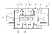
- a plurality of the light sources 5 may be arranged side by side with respect to the circuit board 6.
- the reflector 7 has a (pyramidal) reflecting wall 15 provided individually for each of the light sources 5, and a plurality of the reflecting walls 15 are connected to form an integral connecting reflecting portion 41. Also good.
- the connecting reflection portion 41 may include a frame wall portion 42 that defines the entire outer shape, and a partition wall 43 that partitions the inside of the frame wall portion 42 into a square shape. Further, the frame wall portion 42 may have an extension portion 45 that extends longer in the optical axis direction of the light source 5 than the partition wall 43.
- the number of the light sources 5 to be installed is determined by the shape and size of the display unit 2 and the luminance necessary for illumination of the display unit 2.
- the arrangement of the plurality of light sources 5 relative to the circuit board 6 and the height of the reflector 7 are determined based on the shape and size of the display unit 2 described above, the angle 32 of the reflection wall unit 15, and the like. In this case, three light sources 5 are arranged side by side.
- the height of the partition wall 43 of the connection reflection portion 41 is a position where adjacent inner surfaces (steep slope portions 33) of the plurality of reflection wall portions 15 intersect each other. And if the frame wall part 42 of the connection reflection part 41 is made the same height as the partition wall 43, the shadow of the tip part of the partition wall 43 may be strongly projected on the light exit part 13 of the reflector 7.
- the extension portion 45 is provided in the frame wall portion 42 so that the light 14 from the light source 5 spreads outside the tip end portion of the partition wall 43 in the extension portion 45.
- the length 45a of the extension part 45 is preferably about 0.5 times or more of the height 43a of the partition wall 43. If the extension 45 is made too long, the distance from the light source 5 to the light output part 13 becomes too long. Therefore, the length 45a of the extension 45 is approximately 1.0 times the height 43a of the partition wall 43. It is preferable that In the case of this embodiment, the length 45 a of the extension 45 is about 0.7 times the height 43 a of the partition wall 43.
- the extension portion 45 can be configured only by the steep slope portion 33, but it is necessary to adjust the shape of the frame wall portion 42 so as to match the shape and size of the display portion 2 (or the light output portion 13). In this case, at least a part of the inner surface of the extension 45 is not the steep slope portion 33 but a vertical surface portion 48 that is partially perpendicular to the optical axis 8 in accordance with the display portion 2 (or the light output portion 13). May be.
- a diffusion plate 51 that diffuses the light 14 from the light source 5 may be installed on the surface side of the reflector 7.
- the diffusion plate 51 (or a diffusion sheet, a diffusion filter, etc.) is an optical component for diffusing the light 14 from the light source 5 and making it uniform.
- the diffusing plate 51 is set so as not to remarkably reduce the luminance, and is used as needed.
- the connecting surface portion 18 of the reflector 7 is provided with a diffusing plate attaching portion 57 such as a stepped concave portion 55 and a claw portion 56 along the edge of the light emitting portion 13. Note that when a plurality of pyramidal reflecting wall portions 15 are constructed, only one reflector 7 is provided for the whole.
- a specular reflection layer 61 may be provided at least on the inner surface of the reflection wall portion 15 of the reflector 7.
- the specular reflection layer 61 is, for example, an aluminum vapor deposition layer.
- the specular reflection layer 61 may be provided only on the inner surface of the reflection wall portion 15, but in this case, it is formed on almost the entire reflector 7.
- a head-up display device 73 that projects the image 71 displayed on the display device 1 forward (of the driver's seat in the vehicle) may be provided.
- the display device 1 includes the backlight 3 that illuminates the image 71.
- the backlight 3 is provided with the reflector 7.
- the head-up display device 73 is provided with an image forming device 76 inside the housing 75 and an optical path 77 for guiding the image 71 formed by the image forming device 76 to the outside of the housing 75.
- the housing 75 is provided with an opening 78 for taking out the image 71 guided to the optical path 77 to the outside.
- the opening 78 is provided with a combiner 79 (for example, a translucent projection member) for projecting the image 71.
- a reflecting mirror 81 is appropriately provided for reflecting the image 71 and guiding it to the combiner 79.
- the image forming apparatus 76 is the display apparatus 1 described above, and the display apparatus 1 includes the display unit 2 and the backlight 3 that illuminates the display unit 2 from the back side as described above.
- the display unit 2 is a liquid crystal panel.
- the light 14 from the light source 5 passes through the inside of the reflector 7 installed on the front surface side of the circuit board 6, and the light output portion 13 provided on the tip side of the reflector 7. It is emitted from. Thereby, the display part 2 installed in the front end side of the reflector 7 is illuminated.
- the light 14 from the light source 5 includes a light that has directly passed through the reflector 7 without being reflected (direct light) and a light that has been reflected by the reflector 7 (the reflection wall portion 15) (reflected light). It will be in the state of being condensed by combining. In this way, by condensing and irradiating the light 14 from the light source 5, the luminance can be increased and the illumination can be brightened.
- the shape of the reflection wall portion 15 is reviewed so that the reflector 7 is optimized. That is, the reflecting wall portion 15 of the reflector 7 has a pyramid shape that is similar to the planar shape of the light emitting portion of the light source 5. Then, the four inner surfaces of the pyramidal reflection wall portion 15 are steep slope portions 33 having an angle 32 that can reduce or suppress luminance unevenness while ensuring the maximum luminance 31 of the light source 5. Specifically, the steep slope portion 33 is set to an angle 32 that is larger than 7.5 degrees and smaller than 15 degrees with respect to the direction of the optical axis 8 of the light source 5. As a result, it is possible to reflect the light 14 from the light source 5 in an almost uniform and efficient state.
- the shape of the reflecting surface of the reflector is a rectangular pyramid (a rectangular pyramid having a rectangular cross section), and each surface of the rectangular pyramid is an irradiation angle of a general light source (LED) (120 degrees).
- the slope is a gentle slope (slow slope) that extends to about 60 degrees on one side (120 degrees on both sides) with respect to the optical axis of the light source, the reflection of light by the reflector is hardly used. As a result, the illumination efficiency is lowered, and sufficient luminance cannot be obtained.
- the diffusion plate 51 may be installed on the surface side of the reflector 7. Thereby, when necessary, the diffuser plate 51 is installed, and the light 14 from the light source 5 is diffused by the diffuser plate 51, whereby the luminance unevenness can be further reduced.
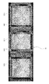
- FIG. 8 is a diagram showing a state of luminance unevenness when the extension 45 is provided and the diffusion plate 51 is provided. According to FIG. 8, the portions of the lamp chambers 21 (illumination rooms) are uneven in luminance. (It is noted that the data image of uneven brightness is different from the color image due to black and white), and the shadow by the tip of the partition wall 43 is within the allowable range. It was confirmed that it became thinner.
- At least the specular reflection layer 61 may be provided on the inner surface of the reflection wall portion 15 of the reflector 7. With this mirror reflection layer 61 (the increase in reflectivity), the light 14 can be reflected without loss and the illumination efficiency can be further increased.
- the head-up display device 73 projects the image 71 formed by the display device 1 on the combiner 79 and displays it as a virtual image so as to enter the field of view of the driver seat occupant driving facing the front. is there. And the backlight 3 provided with the said reflector 7 may be applied with respect to such a head-up display apparatus 73.
- FIG. Thereby, as above-mentioned, the illumination efficiency of the backlight 3 in the head-up display apparatus 73 can be raised. Therefore, a brighter head-up display device 73 can be obtained.
Landscapes
- Physics & Mathematics (AREA)
- General Physics & Mathematics (AREA)
- Optics & Photonics (AREA)
- Engineering & Computer Science (AREA)
- General Engineering & Computer Science (AREA)
- Instrument Panels (AREA)
- Planar Illumination Modules (AREA)
- Non-Portable Lighting Devices Or Systems Thereof (AREA)
- Liquid Crystal (AREA)
Priority Applications (1)
| Application Number | Priority Date | Filing Date | Title |
|---|---|---|---|
| US15/766,709 US10345583B2 (en) | 2015-11-24 | 2016-10-14 | Illumination Structure |
Applications Claiming Priority (2)
| Application Number | Priority Date | Filing Date | Title |
|---|---|---|---|
| JP2015228697A JP6283013B2 (ja) | 2015-11-24 | 2015-11-24 | 照明構造 |
| JP2015-228697 | 2015-11-24 |
Publications (1)
| Publication Number | Publication Date |
|---|---|
| WO2017090335A1 true WO2017090335A1 (ja) | 2017-06-01 |
Family
ID=58763445
Family Applications (1)
| Application Number | Title | Priority Date | Filing Date |
|---|---|---|---|
| PCT/JP2016/080475 Ceased WO2017090335A1 (ja) | 2015-11-24 | 2016-10-14 | 照明構造 |
Country Status (3)
| Country | Link |
|---|---|
| US (1) | US10345583B2 (enExample) |
| JP (1) | JP6283013B2 (enExample) |
| WO (1) | WO2017090335A1 (enExample) |
Cited By (2)
| Publication number | Priority date | Publication date | Assignee | Title |
|---|---|---|---|---|
| US11347102B2 (en) * | 2018-09-04 | 2022-05-31 | Japan Display Inc. | Display device |
| WO2022249557A1 (ja) * | 2021-05-28 | 2022-12-01 | ミネベアミツミ株式会社 | 面状照明装置 |
Families Citing this family (2)
| Publication number | Priority date | Publication date | Assignee | Title |
|---|---|---|---|---|
| JP7214317B2 (ja) * | 2019-02-13 | 2023-01-30 | マレリ株式会社 | ヘッドアップディスプレイ用バックライト装置 |
| CN118591762A (zh) | 2022-12-16 | 2024-09-03 | 京东方科技集团股份有限公司 | 发光基板和虚拟显示装置 |
Citations (3)
| Publication number | Priority date | Publication date | Assignee | Title |
|---|---|---|---|---|
| JP2010211065A (ja) * | 2009-03-11 | 2010-09-24 | Denso Corp | 表示装置 |
| JP2011090949A (ja) * | 2009-10-23 | 2011-05-06 | Sekisui Plastics Co Ltd | 照明体 |
| JP2013247038A (ja) * | 2012-05-28 | 2013-12-09 | Sharp Corp | 照明装置および表示装置 |
Family Cites Families (5)
| Publication number | Priority date | Publication date | Assignee | Title |
|---|---|---|---|---|
| JP2001282118A (ja) | 2000-03-29 | 2001-10-12 | Miyota Kk | 直下型バックライトの製造方法 |
| WO2007023807A1 (ja) * | 2005-08-23 | 2007-03-01 | Kabushiki Kaisha Toshiba | 発光装置とそれを用いたバックライトおよび液晶表示装置 |
| JP4718405B2 (ja) * | 2006-09-19 | 2011-07-06 | シャープ株式会社 | 照明装置 |
| EP2622263B1 (en) | 2010-09-30 | 2014-09-03 | Koninklijke Philips N.V. | Illumination device and luminaire |
| JP2013171874A (ja) | 2012-02-17 | 2013-09-02 | Nk Works Kk | 反射板アレイ、及びこれを備えた光照射装置 |
-
2015
- 2015-11-24 JP JP2015228697A patent/JP6283013B2/ja active Active
-
2016
- 2016-10-14 WO PCT/JP2016/080475 patent/WO2017090335A1/ja not_active Ceased
- 2016-10-14 US US15/766,709 patent/US10345583B2/en active Active
Patent Citations (3)
| Publication number | Priority date | Publication date | Assignee | Title |
|---|---|---|---|---|
| JP2010211065A (ja) * | 2009-03-11 | 2010-09-24 | Denso Corp | 表示装置 |
| JP2011090949A (ja) * | 2009-10-23 | 2011-05-06 | Sekisui Plastics Co Ltd | 照明体 |
| JP2013247038A (ja) * | 2012-05-28 | 2013-12-09 | Sharp Corp | 照明装置および表示装置 |
Cited By (4)
| Publication number | Priority date | Publication date | Assignee | Title |
|---|---|---|---|---|
| US11347102B2 (en) * | 2018-09-04 | 2022-05-31 | Japan Display Inc. | Display device |
| WO2022249557A1 (ja) * | 2021-05-28 | 2022-12-01 | ミネベアミツミ株式会社 | 面状照明装置 |
| JP2022182454A (ja) * | 2021-05-28 | 2022-12-08 | ミネベアミツミ株式会社 | 面状照明装置 |
| JP7386205B2 (ja) | 2021-05-28 | 2023-11-24 | ミネベアミツミ株式会社 | 面状照明装置 |
Also Published As
| Publication number | Publication date |
|---|---|
| US10345583B2 (en) | 2019-07-09 |
| JP2017094901A (ja) | 2017-06-01 |
| US20180321489A1 (en) | 2018-11-08 |
| JP6283013B2 (ja) | 2018-02-21 |
Similar Documents
| Publication | Publication Date | Title |
|---|---|---|
| JP5290279B2 (ja) | 照明システム、照明器具及びバックライティングユニット | |
| JP6746397B2 (ja) | 車両用灯具 | |
| JP2018125137A (ja) | 照明装置 | |
| JP2018122702A (ja) | 照明装置 | |
| KR101804311B1 (ko) | 백라이트 유닛 | |
| JP6283013B2 (ja) | 照明構造 | |
| WO2019116698A1 (ja) | 液晶照明装置、ヘッドアップディスプレイ、及び照明方法 | |
| JP5169806B2 (ja) | 照明装置 | |
| JP2015536029A (ja) | 改良されたlcdバックライトディスプレイ | |
| CN105372871B (zh) | 面光源装置和液晶显示装置 | |
| JP2007234385A (ja) | バックライト装置 | |
| CN1570733B (zh) | 显示系统的背光组件 | |
| JP7769561B2 (ja) | 光学部材、光源装置、およびヘッドアップディスプレイ | |
| EP4435319A1 (en) | Vehicle lamp | |
| EP3361144B1 (en) | Lighting device | |
| JP2005174910A (ja) | バックライト組立体 | |
| JP6329955B2 (ja) | 照明装置及び表示装置 | |
| JP2013218946A (ja) | 照明装置 | |
| WO2017090336A1 (ja) | 放熱構造 | |
| JPWO2019087912A1 (ja) | ヘッドアップディスプレイ装置 | |
| WO2025070724A1 (ja) | 車両用灯具 | |
| JP2017157325A (ja) | 照明装置 | |
| US20090097278A1 (en) | Light Indicator | |
| JP2014211996A (ja) | 照明装置 | |
| US20060221618A1 (en) | Light valve |
Legal Events
| Date | Code | Title | Description |
|---|---|---|---|
| 121 | Ep: the epo has been informed by wipo that ep was designated in this application |
Ref document number: 16868284 Country of ref document: EP Kind code of ref document: A1 |
|
| DPE2 | Request for preliminary examination filed before expiration of 19th month from priority date (pct application filed from 20040101) | ||
| WWE | Wipo information: entry into national phase |
Ref document number: 15766709 Country of ref document: US |
|
| NENP | Non-entry into the national phase |
Ref country code: DE |
|
| 122 | Ep: pct application non-entry in european phase |
Ref document number: 16868284 Country of ref document: EP Kind code of ref document: A1 |