WO2022249557A1 - 面状照明装置 - Google Patents
面状照明装置 Download PDFInfo
- Publication number
- WO2022249557A1 WO2022249557A1 PCT/JP2022/004402 JP2022004402W WO2022249557A1 WO 2022249557 A1 WO2022249557 A1 WO 2022249557A1 JP 2022004402 W JP2022004402 W JP 2022004402W WO 2022249557 A1 WO2022249557 A1 WO 2022249557A1
- Authority
- WO
- WIPO (PCT)
- Prior art keywords
- lens
- axial direction
- light
- surface facing
- illumination device
- Prior art date
Links
- 238000005286 illumination Methods 0.000 title claims abstract description 39
- 230000003287 optical effect Effects 0.000 claims abstract description 45
- 239000000758 substrate Substances 0.000 claims abstract description 30
- 230000000007 visual effect Effects 0.000 claims description 12
- 238000009792 diffusion process Methods 0.000 claims description 8
- 230000004048 modification Effects 0.000 description 48
- 238000012986 modification Methods 0.000 description 48
- 238000010586 diagram Methods 0.000 description 17
- 230000000694 effects Effects 0.000 description 4
- 230000000903 blocking effect Effects 0.000 description 2
- 238000001746 injection moulding Methods 0.000 description 2
- 239000004973 liquid crystal related substance Substances 0.000 description 2
- 239000000470 constituent Substances 0.000 description 1
- 238000006073 displacement reaction Methods 0.000 description 1
- 230000008030 elimination Effects 0.000 description 1
- 238000003379 elimination reaction Methods 0.000 description 1
- 239000011347 resin Substances 0.000 description 1
- 229920005989 resin Polymers 0.000 description 1
Images


Classifications
-
- G—PHYSICS
- G02—OPTICS
- G02F—OPTICAL DEVICES OR ARRANGEMENTS FOR THE CONTROL OF LIGHT BY MODIFICATION OF THE OPTICAL PROPERTIES OF THE MEDIA OF THE ELEMENTS INVOLVED THEREIN; NON-LINEAR OPTICS; FREQUENCY-CHANGING OF LIGHT; OPTICAL LOGIC ELEMENTS; OPTICAL ANALOGUE/DIGITAL CONVERTERS
- G02F1/00—Devices or arrangements for the control of the intensity, colour, phase, polarisation or direction of light arriving from an independent light source, e.g. switching, gating or modulating; Non-linear optics
- G02F1/01—Devices or arrangements for the control of the intensity, colour, phase, polarisation or direction of light arriving from an independent light source, e.g. switching, gating or modulating; Non-linear optics for the control of the intensity, phase, polarisation or colour
- G02F1/13—Devices or arrangements for the control of the intensity, colour, phase, polarisation or direction of light arriving from an independent light source, e.g. switching, gating or modulating; Non-linear optics for the control of the intensity, phase, polarisation or colour based on liquid crystals, e.g. single liquid crystal display cells
- G02F1/133—Constructional arrangements; Operation of liquid crystal cells; Circuit arrangements
- G02F1/1333—Constructional arrangements; Manufacturing methods
- G02F1/1335—Structural association of cells with optical devices, e.g. polarisers or reflectors
- G02F1/1336—Illuminating devices
- G02F1/133602—Direct backlight
- G02F1/133603—Direct backlight with LEDs
-
- F—MECHANICAL ENGINEERING; LIGHTING; HEATING; WEAPONS; BLASTING
- F21—LIGHTING
- F21V—FUNCTIONAL FEATURES OR DETAILS OF LIGHTING DEVICES OR SYSTEMS THEREOF; STRUCTURAL COMBINATIONS OF LIGHTING DEVICES WITH OTHER ARTICLES, NOT OTHERWISE PROVIDED FOR
- F21V5/00—Refractors for light sources
- F21V5/007—Array of lenses or refractors for a cluster of light sources, e.g. for arrangement of multiple light sources in one plane
-
- F—MECHANICAL ENGINEERING; LIGHTING; HEATING; WEAPONS; BLASTING
- F21—LIGHTING
- F21S—NON-PORTABLE LIGHTING DEVICES; SYSTEMS THEREOF; VEHICLE LIGHTING DEVICES SPECIALLY ADAPTED FOR VEHICLE EXTERIORS
- F21S2/00—Systems of lighting devices, not provided for in main groups F21S4/00 - F21S10/00 or F21S19/00, e.g. of modular construction
-
- F—MECHANICAL ENGINEERING; LIGHTING; HEATING; WEAPONS; BLASTING
- F21—LIGHTING
- F21V—FUNCTIONAL FEATURES OR DETAILS OF LIGHTING DEVICES OR SYSTEMS THEREOF; STRUCTURAL COMBINATIONS OF LIGHTING DEVICES WITH OTHER ARTICLES, NOT OTHERWISE PROVIDED FOR
- F21V5/00—Refractors for light sources
- F21V5/04—Refractors for light sources of lens shape
- F21V5/045—Refractors for light sources of lens shape the lens having discontinuous faces, e.g. Fresnel lenses
-
- F—MECHANICAL ENGINEERING; LIGHTING; HEATING; WEAPONS; BLASTING
- F21—LIGHTING
- F21V—FUNCTIONAL FEATURES OR DETAILS OF LIGHTING DEVICES OR SYSTEMS THEREOF; STRUCTURAL COMBINATIONS OF LIGHTING DEVICES WITH OTHER ARTICLES, NOT OTHERWISE PROVIDED FOR
- F21V7/00—Reflectors for light sources
- F21V7/0083—Array of reflectors for a cluster of light sources, e.g. arrangement of multiple light sources in one plane
-
- G—PHYSICS
- G02—OPTICS
- G02F—OPTICAL DEVICES OR ARRANGEMENTS FOR THE CONTROL OF LIGHT BY MODIFICATION OF THE OPTICAL PROPERTIES OF THE MEDIA OF THE ELEMENTS INVOLVED THEREIN; NON-LINEAR OPTICS; FREQUENCY-CHANGING OF LIGHT; OPTICAL LOGIC ELEMENTS; OPTICAL ANALOGUE/DIGITAL CONVERTERS
- G02F1/00—Devices or arrangements for the control of the intensity, colour, phase, polarisation or direction of light arriving from an independent light source, e.g. switching, gating or modulating; Non-linear optics
- G02F1/01—Devices or arrangements for the control of the intensity, colour, phase, polarisation or direction of light arriving from an independent light source, e.g. switching, gating or modulating; Non-linear optics for the control of the intensity, phase, polarisation or colour
- G02F1/13—Devices or arrangements for the control of the intensity, colour, phase, polarisation or direction of light arriving from an independent light source, e.g. switching, gating or modulating; Non-linear optics for the control of the intensity, phase, polarisation or colour based on liquid crystals, e.g. single liquid crystal display cells
- G02F1/133—Constructional arrangements; Operation of liquid crystal cells; Circuit arrangements
- G02F1/1333—Constructional arrangements; Manufacturing methods
- G02F1/1335—Structural association of cells with optical devices, e.g. polarisers or reflectors
- G02F1/1336—Illuminating devices
- G02F1/133602—Direct backlight
- G02F1/133605—Direct backlight including specially adapted reflectors
-
- G—PHYSICS
- G02—OPTICS
- G02F—OPTICAL DEVICES OR ARRANGEMENTS FOR THE CONTROL OF LIGHT BY MODIFICATION OF THE OPTICAL PROPERTIES OF THE MEDIA OF THE ELEMENTS INVOLVED THEREIN; NON-LINEAR OPTICS; FREQUENCY-CHANGING OF LIGHT; OPTICAL LOGIC ELEMENTS; OPTICAL ANALOGUE/DIGITAL CONVERTERS
- G02F1/00—Devices or arrangements for the control of the intensity, colour, phase, polarisation or direction of light arriving from an independent light source, e.g. switching, gating or modulating; Non-linear optics
- G02F1/01—Devices or arrangements for the control of the intensity, colour, phase, polarisation or direction of light arriving from an independent light source, e.g. switching, gating or modulating; Non-linear optics for the control of the intensity, phase, polarisation or colour
- G02F1/13—Devices or arrangements for the control of the intensity, colour, phase, polarisation or direction of light arriving from an independent light source, e.g. switching, gating or modulating; Non-linear optics for the control of the intensity, phase, polarisation or colour based on liquid crystals, e.g. single liquid crystal display cells
- G02F1/133—Constructional arrangements; Operation of liquid crystal cells; Circuit arrangements
- G02F1/1333—Constructional arrangements; Manufacturing methods
- G02F1/1335—Structural association of cells with optical devices, e.g. polarisers or reflectors
- G02F1/1336—Illuminating devices
- G02F1/133602—Direct backlight
- G02F1/133606—Direct backlight including a specially adapted diffusing, scattering or light controlling members
- G02F1/133607—Direct backlight including a specially adapted diffusing, scattering or light controlling members the light controlling member including light directing or refracting elements, e.g. prisms or lenses
-
- G—PHYSICS
- G02—OPTICS
- G02F—OPTICAL DEVICES OR ARRANGEMENTS FOR THE CONTROL OF LIGHT BY MODIFICATION OF THE OPTICAL PROPERTIES OF THE MEDIA OF THE ELEMENTS INVOLVED THEREIN; NON-LINEAR OPTICS; FREQUENCY-CHANGING OF LIGHT; OPTICAL LOGIC ELEMENTS; OPTICAL ANALOGUE/DIGITAL CONVERTERS
- G02F1/00—Devices or arrangements for the control of the intensity, colour, phase, polarisation or direction of light arriving from an independent light source, e.g. switching, gating or modulating; Non-linear optics
- G02F1/01—Devices or arrangements for the control of the intensity, colour, phase, polarisation or direction of light arriving from an independent light source, e.g. switching, gating or modulating; Non-linear optics for the control of the intensity, phase, polarisation or colour
- G02F1/13—Devices or arrangements for the control of the intensity, colour, phase, polarisation or direction of light arriving from an independent light source, e.g. switching, gating or modulating; Non-linear optics for the control of the intensity, phase, polarisation or colour based on liquid crystals, e.g. single liquid crystal display cells
- G02F1/133—Constructional arrangements; Operation of liquid crystal cells; Circuit arrangements
- G02F1/1333—Constructional arrangements; Manufacturing methods
- G02F1/1335—Structural association of cells with optical devices, e.g. polarisers or reflectors
- G02F1/1336—Illuminating devices
- G02F1/133602—Direct backlight
- G02F1/133611—Direct backlight including means for improving the brightness uniformity
-
- F—MECHANICAL ENGINEERING; LIGHTING; HEATING; WEAPONS; BLASTING
- F21—LIGHTING
- F21Y—INDEXING SCHEME ASSOCIATED WITH SUBCLASSES F21K, F21L, F21S and F21V, RELATING TO THE FORM OR THE KIND OF THE LIGHT SOURCES OR OF THE COLOUR OF THE LIGHT EMITTED
- F21Y2105/00—Planar light sources
- F21Y2105/10—Planar light sources comprising a two-dimensional array of point-like light-generating elements
-
- F—MECHANICAL ENGINEERING; LIGHTING; HEATING; WEAPONS; BLASTING
- F21—LIGHTING
- F21Y—INDEXING SCHEME ASSOCIATED WITH SUBCLASSES F21K, F21L, F21S and F21V, RELATING TO THE FORM OR THE KIND OF THE LIGHT SOURCES OR OF THE COLOUR OF THE LIGHT EMITTED
- F21Y2113/00—Combination of light sources
-
- F—MECHANICAL ENGINEERING; LIGHTING; HEATING; WEAPONS; BLASTING
- F21—LIGHTING
- F21Y—INDEXING SCHEME ASSOCIATED WITH SUBCLASSES F21K, F21L, F21S and F21V, RELATING TO THE FORM OR THE KIND OF THE LIGHT SOURCES OR OF THE COLOUR OF THE LIGHT EMITTED
- F21Y2115/00—Light-generating elements of semiconductor light sources
- F21Y2115/10—Light-emitting diodes [LED]
Definitions
- the present invention relates to a planar lighting device.
- the present invention has been made in view of the above, and it is an object of the present invention to provide a planar lighting device capable of realizing required light distribution characteristics while ensuring high brightness.
- a planar illumination device includes a substrate, a first optical element, and a second optical element.
- a plurality of light sources are two-dimensionally arranged on the substrate.
- the first optical element is arranged on the emission side of the plurality of light sources and condenses the light emitted from the plurality of light sources.
- the second optical element tilts the light distribution of the light condensed by the first optical element with respect to the first axial direction.
- a planar lighting device can realize required light distribution characteristics while ensuring high luminance.
- FIG. 1 is a diagram for explaining light distribution characteristics required for a planar lighting device according to an embodiment.
- FIG. 2 is a diagram for explaining the outline of the planar illumination device shown in FIG.
- FIG. 3 is a perspective view schematically showing the configuration of the planar lighting device shown in FIG. 4A and 4B are cross-sectional views taken along line AA and line BB of the planar illumination device shown in FIG. 5 is a perspective view of the reflector shown in FIG. 3.
- FIG. 6A and 6B are a front view, a CC sectional view, and a DD sectional view of the reflector shown in FIG.
- FIG. 7 is a diagram for explaining a first modified example.
- FIG. 8 is a diagram for explaining a second modification.
- FIG. 1 is a diagram for explaining light distribution characteristics required for a planar lighting device according to an embodiment.
- FIG. 2 is a diagram for explaining the outline of the planar illumination device shown in FIG.
- FIG. 3 is a perspective view schematically showing the
- FIG. 9 is a diagram for explaining a third modification.
- FIG. 10 is a diagram for explaining a fourth modification.
- FIG. 11 is a diagram for explaining a fifth modification.
- FIG. 12 is a diagram for explaining a sixth modification.
- FIG. 13 is a diagram for explaining a seventh modification.
- a planar illumination device will be described below with reference to the drawings.
- this invention is not limited by this embodiment.
- the dimensional relationship of each element in the drawings, the ratio of each element, and the like may differ from reality. Even between the drawings, there are cases where portions with different dimensional relationships and ratios are included. In principle, the contents described in one embodiment and modification are similarly applied to other embodiments and modifications.
- FIG. 1 is a diagram for explaining light distribution characteristics required for a planar illumination device 1 according to an embodiment.
- FIG. 1 is an outline view of a planar lighting device 1 according to the embodiment. is the Z direction.
- the planar lighting device 1 has a substantially rectangular plate-like outer shape, and light is emitted from the inside of the opening 9 a of the frame 9 . It should be noted that the outer shape of the planar illumination device 1 is not limited to that illustrated. "Optical axis shift" shown in the figure means tilting the optical axis.
- the optical axis is tilted to the negative direction side of the Y axis of the planar lighting device 1 (diagonally to the lower right in the figure), indicating that a narrow visual field range is required.
- the light distribution characteristic in the X-axis direction of the planar lighting device 1 indicates that a wide visual field range is required with the normal direction of the light emitting surface as the optical axis.
- the planar illumination device 1 includes a first optical element that collects the light emitted from the light source, and a second optical element that tilts the light distribution of the light collected by the first optical element with respect to the Y-axis direction. and an optical element of The Y-axis direction is an example of a first axial direction. Note that the embodiment can be applied even when the first axial direction is the X-axis direction. A configuration example of the planar illumination device 1 of the embodiment will be described in detail below.
- FIG. 2 is a diagram for explaining the outline of the planar illumination device shown in FIG.
- FIG. 2 is a simplified view of the AA cross-sectional view of the planar lighting device 1 shown in FIG. Frame 9 is omitted in FIG.
- the AA cross-sectional view may be referred to as a vertical cross-sectional view.
- the BB cross-sectional view of the planar illumination device 1 shown in FIG. 1 may be referred to as a cross-sectional view.
- a plurality of light sources 3 such as LEDs (Light Emitting Diodes) are arranged on the substrate 2 .
- FIG. 2 shows a plurality of light sources 3 arranged in the Y-axis direction, a plurality of light sources 3 are also arranged in the X-axis direction (see FIG. 4 described later). That is, a plurality of light sources 3 are two-dimensionally arranged on the substrate 2 . Each of the plurality of light sources 3 is driven individually and can cope with so-called local dimming.
- a condenser lens 5 provided with a first optical element for condensing the light emitted from the plurality of light sources 3 is arranged on the emission side of the plurality of light sources 3 , and the light emitted from the plurality of light sources 3 is condensed by the condenser lens 5 .
- a light distribution lens 6 provided with a second optical element for tilting the distribution of light with respect to the Y-axis direction is arranged.
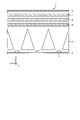
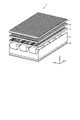
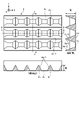
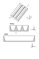
- FIG. 3 is a perspective view schematically showing the planar illumination device 1 shown in FIG. 1, and FIG. 4 is a sectional view taken along line AA and BB of the planar illumination device shown in FIG.
- the left figure in FIG. 4 is a vertical sectional view taken along line AA, and the right figure in FIG. 4 is a horizontal sectional view taken along line BB.
- the longitudinal sectional view of FIG. 4 schematically shows the behavior of light rays with respect to the Y-axis direction
- the transverse view of FIG. 4 schematically shows the behavior of light rays with respect to the X-axis direction.
- the condenser lens 5 extends in the X-axis direction orthogonal to the Y-axis direction, and has a linear Fresnel lens 5a as a first optical element that collects the light emitted from the plurality of light sources 3 in the Y-axis direction. have.
- the linear Fresnel lens 5a is provided on the surface opposite to the surface facing the substrate 2 (surface on the output side of the condenser lens 5). Note that the X-axis direction is an example of the second axial direction.
- the linear Fresnel lens 5a has a prism structure in which a cylindrical convex lens is a Fresnel lens, and has grooves extending in the X-axis direction.
- grooves are periodically formed in accordance with the pitch of the light sources 3 (pitch in the Y-axis direction) arranged directly below.
- the light distributing lens 6 has a linear prism 6a extending in the X-axis direction as a second optical element that tilts the light distribution of the light condensed by the condensing lens 5 with respect to the Y-axis direction.
- the linear prism 6a is provided on the surface opposite to the surface facing the condenser lens 5 (the exit-side surface of the light distribution lens 6).
- the linear prisms 6a have a substantially triangular prism structure extending in the X-axis direction and are arranged continuously in the Y-axis direction. As a result, grooves extending in the X-axis direction are formed on the exit-side surface of the light distributing lens 6 .
- the cross-sectional shape of the YZ plane of the linear prism 6a is a triangle, and the base angle of the side connecting the point on the positive Y-axis side of the base and the vertex is the point on the negative Y-axis side of the base and the vertex. smaller than the base angle of the side connecting
- the light emitted from the light source 3 enters the condenser lens 5 and is substantially refracted by the linear Fresnel lens 5a provided on the upper surface of the condenser lens 5.
- the light emitted from the condenser lens 5 enters the light distribution lens 6 and is substantially refracted by the linear prism 6a provided on the upper surface of the light distribution lens 6. output without
- the condenser lens 5 collects the light emitted from the plurality of light sources 3 and makes it enter the light distribution lens 6 as substantially parallel light efficiently. emits incident light with its optical axis tilted.
- the planar illumination device 1 can achieve the required light distribution characteristics with high luminance.
- the optical axis shift is not required in the X-axis direction, and the required field of view range is relatively wide. no need to focus.
- the condenser lens 5 of the embodiment is not provided with a linear Fresnel lens extending in the Y-axis direction, and the light distributing lens 6 is not provided with a linear prism extending in the Y-axis direction. .
- the effects of such a configuration will be detailed later.
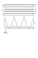
- the planar illumination device 1 has a viewing range adjusting lens as shown in FIGS. 7 is arranged on the output side of the light distributing lens 6 .
- the field-of-view range adjusting lens 7 has a first lenticular lens 7a provided on the surface facing the light distributing lens 6 (surface on the incident side) and the surface facing the light distributing lens 6. and a second lenticular lens 7b provided on the side surface (the surface on the leaving side).
- the first lenticular lens 7a extends in the X-axis direction and adjusts the viewing range in the Y-axis direction.
- the first lenticular lens 7a has a semicylindrical fine semicylindrical prism structure extending in the X-axis direction.
- the second lenticular lens 7b extends in the Y-axis direction and adjusts the luminance distribution in the X-axis direction.
- the second lenticular lens 7b has a semicylindrical fine semicylindrical prism structure extending in the Y-axis direction.
- a linear Fresnel lens that collects light, a linear prism that tilts toward the target optical axis, and a lenticular lens that both collects and diffuses light to adjust the viewing range and luminance distribution are combined. This makes it possible to control the light distribution to the target visual field range while ensuring high brightness and uniformity.
- the planar illumination device 1 may have a diffusion sheet 8 arranged on the output side of the viewing range adjusting lens 7 as shown in FIG.
- the diffusion sheet 8 is useful for eliminating streaky unevenness caused by the first lenticular lens 7a and the second lenticular lens 7b.
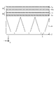
- a plurality of light sources 3 are emitted between the plurality of light sources 3 and the condenser lens 5.
- a reflector 4 is arranged in order to allow the light to enter the condensing lens 5 efficiently.
- the reflector 4 is formed so that openings 4b corresponding to the plurality of light sources 3 are arranged, and has a wall portion 4c that surrounds the openings 4b and serves as a reflecting surface 4a.
- reflector 4 has four reflective surfaces 4a surrounding opening 4b.
- the planar illumination device 1 of the embodiment is required to have a field of view characteristic of a wide field of view in the X-axis direction and a narrow field of view in the Y-axis direction.
- visual field characteristics are realized mainly by controlling the optical characteristics by the lens functions of the condenser lens 5, the light distributing lens 6, the visual field range adjusting lens 7, and the like.
- the structure of the reflector 4 located between the light source 3 and the lens may change the viewing characteristics obtained through the lens. Therefore, matching the structure of the reflector 4 with the required characteristics is preferable for ensuring the control of the light distribution to the target visual field range realized by the lens function described above.
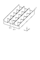
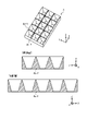
- FIG. 5 is a perspective view of the reflector shown in FIG. 3
- FIG. 6 is a front view, CC sectional view (vertical section) and DD sectional view (lateral section) of the reflector shown in FIG.
- the wall portion 4c has a shape in which a plurality of first wall portions 4c-1 extending in the Y-axis direction and a plurality of second wall portions 4c-2 extending in the X-axis direction are assembled in a lattice. ing.
- the wall portion 4c is assembled so that the bottom surface of the first wall portion 4c-1 and the bottom surface of the second wall portion 4c-2 are flush with each other.
- the reflecting surface 4a is the wall surface of the wall portion 4c.
- the two reflecting surfaces 4a-1 facing each other between the two first walls 4c-1 adjacent in the X-axis direction are inclined away from each other toward the positive Z-axis direction.
- the reflector 4 is made of, for example, white resin or the like in order to enhance the effect of reflection.
- the reflector 4 of the embodiment is an injection-molded product.
- the height of the first wall portion 4c-1 is defined by the viewing range in the X-axis direction
- the height of the second wall portion 4c-2 is defined by the viewing range in the Y-axis direction.
- the height of the second wall portion 4c-2 is increased as shown in the longitudinal section of FIG.
- increasing the height of the second wall portion 4c-2 also plays a role of blocking light entering the linear Fresnel lens 5a of the adjacent segment, and also has a function of avoiding unintended light distribution. .
- the height of the second wall portion 4c-2 extending in the X-axis direction (longitudinal direction) is higher than the height of the first wall portion 4c-1 extending in the Y-axis direction (lateral direction).
- the reflector 4 of the embodiment is arranged so that the opening 4b is located on the emission side of the light emitting surface of the light source 3, as shown in FIG.
- a light emitting surface of the light source 3 corresponds to the top surface of the light source 3 .
- the bottom surface 4d of the wall portion 4c of the reflector 4 is positioned above the light emitting surface of the light source 3, floating above the substrate 2. As shown in FIG.
- the visual field range adjusting lens 7 is provided with lenticular lenses in both the X-axis direction and the Y-axis direction. However, since the lenticular lenses have the same shape and pattern, there is no need to consider lens displacement.
- the wall portion 4c of the reflector 4 and the light source 3 are in close proximity, and when the reflector 4 and the light source 3 expand and contract, they may interfere with each other.
- the opening 4b of the reflector 4 is arranged at a position higher than the light emitting surface of the light source 3, even if the reflector 4 and the light source 3 expand and contract, the wall portion 4c of the reflector 4 and There is no possibility of contact with the light source 3.
- the opening 4b of the reflector 4 can be made smaller than the outer periphery of the light source 3 as long as it is larger than the light emitting surface of the light source 3 in top view. That is, in the embodiment, the opening 4b can be made smaller.
- the bottom surface 4d can be enlarged, and as a result, the walls 4c of the reflector 4, which are made by injection molding, can be raised. For this reason, in the embodiment, effects such as high contrast during local dimming and elimination of unnecessary light distribution can be obtained.
- planar illumination device 1 described in the above embodiment is merely an example, and various modifications are possible. Modifications of the planar illumination device 1 will be described below.
- the planar illumination device 1 of the first modification has the same prism structure (linear Fresnel lens 5a, linear prism 6a, first lenticular lens 7a, second lenticular lens 7b) as in the embodiment, but each prism
- the arrangement of structures differs from the embodiment.
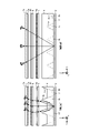
- FIG. 7 is a diagram for explaining the first modified example.
- the planar illumination device 1 of the first modified example includes, as the first lens, a condensing lens 5 provided with a linear Fresnel lens 5a on the surface opposite to the surface facing the substrate 2, as in the embodiment. is provided as the first lens.
- the planar illumination device 1 of the first modified example includes a second lens 60 and a third lens 70 .
- the second lens 60 has a second lenticular lens 7b provided on the surface facing the first lens (condensing lens 5), and the surface opposite to the surface facing the first lens (condensing lens 5).
- a linear prism 6a extending in the X-axis direction is provided.
- the third lens 70 is provided with the first lenticular lens 7 a on the surface facing the second lens 60 .
- the light emitted from the light source 3 is condensed by the emission surface of the light distribution lens 5 (first lens) to become substantially parallel light, and the emission surface of the second lens 60
- the optical axis is tilted at , and the viewing range is adjusted at the incident surface of the third lens 70 .
- the luminance distribution of the light emitted from the light source 3 is adjusted by the incident surface of the second lens 60 in the X-axis direction. Even with such a configuration order of the lenses, it is possible to achieve the required light distribution characteristics while ensuring high brightness, as in the embodiment.
- a diffusion surface 80 is formed on the surface of the third lens 70 opposite to the surface facing the second lens 60 .
- the diffusion surface 80 having the same function as the diffusion sheet 8 is formed on the upper surface of the third lens 70. can reduce the number of parts.
- the planar illumination device 1 of the second modification has the same prism structure (linear Fresnel lens 5a, linear prism 6a, first lenticular lens 7a, second lenticular lens 7b) as in the embodiment, but each prism
- the arrangement of structures and the number of lenses are different from the embodiment.
- FIG. 8 is a diagram for explaining the second modification.
- the planar lighting device 1 of the second modified example includes a first lens 51 and a second lens 61 .
- the first lens 51 has a linear Fresnel lens 5 a provided on the surface facing the substrate 2 and a linear prism 6 a provided on the surface opposite to the surface facing the substrate 2 .
- the second lens 61 is arranged on the output side of the first lens 51, and the second lenticular lens 7b is provided on the surface facing the first lens.
- a first lenticular lens 7a is provided on the surface.
- the light emitted from the light source 3 is condensed on the incident surface of the first lens 51 to become substantially parallel light, and the optical axis is tilted on the output surface of the first lens 51.
- the field of view range is adjusted by the output surface of the second lens 61 .
- the luminance distribution of the light emitted from the light source 3 is adjusted by the incident surface of the second lens 61 in the X-axis direction. Even with such a configuration order of the lenses, it is possible to achieve the required light distribution characteristics while ensuring high brightness, as in the embodiment.
- the planar illumination device 1 of the third modification includes two lenses, and prisms (linear Fresnel lens 5a, first lenticular lens 7a, second Although it has a lenticular lens 7b), the shape of the linear prism for optical axis shift is different from that of the linear prism 6a.
- FIG. 9 is a diagram for explaining the third modification.
- a planar illumination device 1 of the third modification includes a first lens 52 and a second lens 62 .
- the first lens 52 has a linear Fresnel lens 5 a provided on the surface facing the substrate 2 and a second lenticular lens 7 b provided on the surface opposite to the surface facing the substrate 2 .
- the second lens 62 has a linear prism 62a extending in the X-axis direction as a second optical element.
- a first lenticular lens 7a is provided on the surface opposite to the surface facing the lens.
- the linear prisms 62a have a substantially triangular prism structure extending in the X-axis direction and are arranged continuously in the Y-axis direction.
- the cross-sectional shape of the YZ plane of the linear prism 62a is an inverted triangle. greater than the base angle of the side connecting the vertex.
- the light emitted from the light source 3 is condensed by the incident surface of the first lens 52 and becomes substantially parallel light, and the optical axis is tilted by the incident surface of the second lens 62. , and the viewing range is adjusted by the output surface of the second lens 62 .
- the luminance distribution of the light emitted from the light source 3 is adjusted by the emission surface of the first lens 52 in the X-axis direction. Even with such a configuration order of the lenses, it is possible to achieve the required light distribution characteristics while ensuring high brightness, as in the embodiment.
- the lens configuration is not limited to Modifications 1 to 3 above.
- the first lens 52 may have any configuration, such as providing the second lenticular lens 7b on the entrance surface and providing the linear Fresnel lens 5a on the exit surface.
- the bottom surface of the reflector 4 is arranged at a position higher than the light emitting surface of the light source 3. If possible, the bottom surface of the reflector 4 may be grounded to the substrate 2 .
- FIG. 10 is a diagram for explaining a fourth modification.
- the height of the first wall portion 4c-1 is adjusted to match the viewing range in the X-axis direction
- the height of the second wall portion 4c-2 is adjusted to match the viewing range in the Y-axis direction. I was adjusting accordingly.
- the height of the first wall portion 4c-1 and the height of the second wall portion 4c-2 height is the same height.
- FIG. 11 is a diagram for explaining a fifth modification.
- the fifth modification has a reflector structure in which no reflective surface extending in the Y-axis direction is provided between adjacent light sources 3 in the X-axis direction, which is the direction in which the field of view is widened. .
- the wall portions 4c extend in the X-axis direction and are arranged along the Y-axis direction in accordance with the intervals at which the plurality of light sources 3 are arranged in the Y-axis direction.
- the height of the wall portion 4c is defined by the visual field range in the Y-axis direction.
- FIG. 12 is a diagram for explaining a sixth modification.
- light is collected only in the Y-axis direction of the substrate 2, but light may also be collected in the X-axis direction of the substrate 2 as long as the required light distribution characteristics can be achieved.
- a linear Fresnel lens 5a which is a first linear Fresnel lens extending in the X-axis direction and condensing light in the Y-axis direction, is used as the first optical element.
- a second linear Fresnel lens 5b extending in the Y-axis direction and condensing light in the X-axis direction.
- the second linear Fresnel lens 5b has a prism structure using a cylindrical convex lens as a Fresnel lens, and has grooves extending in the Y-axis direction.
- the condenser lens 5 of the sixth modification shown in FIG. 12 has the second linear Fresnel lens 5b on the incident side and the first linear Fresnel lens 5a on the outgoing side. good.
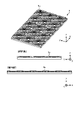
- the seventh modified example a modified example of the condensing lens 5 that has a prism structure different from that in the sixth modified example and collects light in both the Y-axis direction and the X-axis direction will be described.
- a concentric fresnel lens 5c that collects light in the Y-axis direction and the X-axis direction is provided as the first optical element.
- the concentric Fresnel lens 5c is a lens obtained by dividing a convex lens into concentric regions to reduce the thickness, and has a serrated cross section.
- the concentric Fresnel lenses 5c are provided for the number of light sources 3 corresponding to the light sources 3 arranged directly below.
- the condensing lens 5 of the seventh modification shown in FIG. 13 has a concentric Fresnel lens 5c on the output side, but it may be provided on the incident side.
- light distribution control is performed by prisms such as the linear Fresnel lens 5a, the first lenticular lens 7a, the second lenticular lens 7b, and the reflector.
- prisms such as the linear Fresnel lens 5a, the first lenticular lens 7a, the second lenticular lens 7b, and the reflector.
- the present invention is not limited by the above embodiments.
- the present invention also includes those configured by appropriately combining the respective constituent elements described above. Further effects and modifications can be easily derived by those skilled in the art. Therefore, broader aspects of the present invention are not limited to the above-described embodiments, and various modifications are possible.
- 1 planar lighting device 2 substrate, 3 light source, 4 reflector, 4a, 4a-1, 4b-1 reflective surface, 4b aperture, 4c wall, 4c-1 first wall, 4c-2 second wall Part, 5 condenser lens, 5a linear Fresnel lens (first linear Fresnel lens), 6 light distributing lens, 6a linear prism, 7 field range adjusting lens, 7a first lenticular lens, 7b second lenticular lens, 8 Diffusion sheet, 9 frames
Landscapes
- Physics & Mathematics (AREA)
- Nonlinear Science (AREA)
- General Engineering & Computer Science (AREA)
- Engineering & Computer Science (AREA)
- Mathematical Physics (AREA)
- Crystallography & Structural Chemistry (AREA)
- Chemical & Material Sciences (AREA)
- General Physics & Mathematics (AREA)
- Optics & Photonics (AREA)
- Planar Illumination Modules (AREA)
- Liquid Crystal (AREA)
- Non-Portable Lighting Devices Or Systems Thereof (AREA)
- Optical Elements Other Than Lenses (AREA)
Abstract
Description
図1は、実施形態にかかる面状照明装置1に要求される配光特性を説明するための図である。図1は、実施形態にかかる面状照明装置1の外形図であり、図1では、便宜上、面状照明装置1の発光面がX-Y平面内にあり、面状照明装置1の厚み方向をZ方向としている。
上記実施形態で説明した面状照明装置1はあくまでも一例であり、種々の変更が可能である。以下では、面状照明装置1の変形例について説明する。
第1の変形例の面状照明装置1は、実施形態と同様のプリズム構造(リニアフレネルレンズ5a、リニアプリズム6a、第1のレンチキュラーレンズ7a、第2のレンチキュラーレンズ7b)を有するが、各プリズム構造の配置が、実施形態と異なる。
第2の変形例の面状照明装置1は、実施形態と同様のプリズム構造(リニアフレネルレンズ5a、リニアプリズム6a、第1のレンチキュラーレンズ7a、第2のレンチキュラーレンズ7b)を有するが、各プリズム構造の配置とレンズ点数が、実施形態と異なる。
第3の変形例の面状照明装置1は、第2の変形例と同様、2つのレンズで構成され、実施形態と同様のプリズム(リニアフレネルレンズ5a、第1のレンチキュラーレンズ7a、第2のレンチキュラーレンズ7b)を有するが、光軸シフト用のリニアプリズムの形状がリニアプリズム6aと異なる。
第4の変形例では、リフレクタの変形例について説明する。図10は、第4の変形例を説明するための図である。上述したように、第1の壁部4c-1の高さは、X軸方向の視野範囲に合わせて調整し、第2の壁部4c-2の高さは、Y軸方向の視野範囲に合わせて調整していた。図10に示す第4の変形例では、Y軸方向もX軸方向も同程度の狭い視野範囲であることから、第1の壁部4c-1の高さと第2の壁部4c-2の高さとが同じ高さとなっている。
第5の変形例でも、リフレクタの変形例について説明する。図11は、第5の変形例を説明するための図である。第5の変形例は、図11に示すように、広視野となる方向であるX軸方向については、隣り合う光源3の間にY軸方向に延在する反射面を設けないリフレクタ構造となる。
第6の変形例では、実施形態で説明した集光レンズ5の変形例について説明する。図12は、第6の変形例を説明するための図である。上記では、基板2のY軸方向に対する集光のみを行っていたが、要求される配光特性を実現できるのであれば、基板2のX軸方向に対する集光も行っても良い。
第7の変形例では、第6の変形例とは異なるプリズム構造で、Y軸方向もX軸方向も集光する集光レンズ5の変形例を説明する。第7の変形例では、図13に示すように、第1光学素子として、Y軸方向及びX軸方向に対して集光する同心円フレネルレンズ5cを有する。同心円フレネルレンズ5cは、凸レンズを同心円状の領域に分割し厚みを減らしたレンズであり、のこぎり状の断面を持つ。同心円フレネルレンズ5cは、直下に配置される光源3に対応して、光源3の灯数分設けられる。図13に示す第7の変形例の集光レンズ5は、出射側に同心円フレネルレンズ5cを設けているが、入射側に設けても良い。
Claims (16)
- 複数の光源が2次元に配置された基板と、
前記複数の光源の出射側に配置され、前記複数の光源から出射された光を集光する第1の光学素子と、
前記第1の光学素子によって集光された光の配光を第1の軸方向に対して傾ける第2の光学素子と、
を備える、面状照明装置。 - 前記第1の軸方向と直交する第2の軸方向に延在し、前記第1の軸方向における視野範囲を調整する第1のレンチキュラーレンズと、
前記第1の軸方向に延在し、輝度分布を調整する第2のレンチキュラーレンズと、
を更に備える、請求項1に記載の面状照明装置。 - 前記第1の軸方向と直交する第2の軸方向に延在し、前記複数の光源から出射された光を前記第1の軸方向に対して集光するリニアフレネルレンズを前記第1の光学素子として有し、前記基板に対向する面とは反対側の面に前記リニアフレネルレンズが設けられる集光レンズと、
前記第2の軸方向に延在するリニアプリズムを前記第2の光学素子として有し、前記集光レンズに対向する面とは反対側の面に前記リニアプリズムが設けられる配光レンズと、
前記配光レンズの出射側に配置され、前記配光レンズに対向する面に前記第1のレンチキュラーレンズが設けられ、前記配光レンズに対向する面とは反対側の面に前記第2のレンチキュラーレンズが設けられる視野範囲調整レンズと、
を備える、請求項2に記載の面状照明装置。 - 前記視野範囲調整レンズの出射側に配置される拡散シート、
を更に備える、請求項3に記載の面状照明装置。 - 前記第1の軸方向と直交する第2の軸方向に延在し、前記複数の光源から出射された光を前記第1の軸方向に対して集光するリニアフレネルレンズを前記第1の光学素子として有し、前記基板に対向する面とは反対側の面に前記リニアフレネルレンズが設けられる第1レンズと、
前記第1レンズに対向する面に前記第2のレンチキュラーレンズが設けられ、前記第1レンズに対向する面とは反対側の面に前記第2の光学素子として前記第2の軸方向に延在するリニアプリズムが設けられる第2レンズと、
前記第2レンズに対向する面に前記第1のレンチキュラーレンズが設けられる第3レンズと、
を備える、請求項2に記載の面状照明装置。 - 前記第3レンズは、前記第2レンズに対向する面とは反対側の面に拡散面が形成されている、請求項5に記載の面状照明装置。
- 前記第1の軸方向と直交する第2の軸方向に延在し、前記複数の光源から出射された光を前記第1の軸方向に対して集光するリニアフレネルレンズを前記第1の光学素子として有し、前記第2の軸方向に延在するリニアプリズムを前記第2の光学素子として有し、前記基板に対向する面に前記リニアフレネルレンズが設けられ、前記基板に対向する面とは反対側の面に前記リニアプリズムが設けられた第1レンズと、
前記第1レンズの出射側に配置され、前記第1レンズに対向する面に前記第2のレンチキュラーレンズが設けられ、前記第1レンズに対向する面とは反対側の面に前記第1のレンチキュラーレンズが設けられる第2レンズと、
を備える、請求項2に記載の面状照明装置。 - 前記第1の軸方向と直交する第2の軸方向に延在し、前記複数の光源から出射された光を前記第1の軸方向に対して集光するリニアフレネルレンズを前記第1の光学素子として有し、前記基板に対向する面に前記リニアフレネルレンズが設けられ、前記基板に対向する面とは反対側の面に前記第2のレンチキュラーレンズが設けられた第1レンズと、
前記第2の軸方向に延在するリニアプリズムを前記第2の光学素子として有し、前記第1レンズに対向する面に前記リニアプリズムが設けられ、前記第1レンズに対向する面とは反対側の面に前記第1のレンチキュラーレンズが設けられる第2レンズと、
を備える、請求項2に記載の面状照明装置。 - 前記第1の光学素子として、前記第1の軸方向と直交する第2の軸方向に延在し、前記第1の軸方向に対して集光する第1のリニアフレネルレンズと、前記第1の軸方向に延在し、前記第1の軸方向と直交する第2の軸方向に対して集光する第2のリニアフレネルレンズを有する、請求項2に記載の面状照明装置。
- 前記第1の光学素子として、前記第1の軸方向及び前記第1の軸方向と直交する第2の軸方向に対して集光する同心円フレネルレンズを有する、請求項2に記載の面状照明装置。
- 前記複数の光源それぞれに対応する開口が配列されるように形成され、前記開口を囲う壁面が反射面となる壁部を有するリフレクタ、
を備え、
前記壁部は、前記第1の軸方向に延在する複数の第1の壁部と前記第1の軸方向と直交する第2の軸方向に延在する複数の第2の壁部とを格子状に組み立てた形状であり、
前記第1の壁部の高さは、前記第2の軸方向に対する視野範囲により規定され、
前記第2の壁部の高さは、前記第1の軸方向に対する視野範囲により規定される、請求項1~10のいずれか1つに記載の面状照明装置。 - 前記壁部の底面は、前記光源の発光面より出射側に位置するように配置される、請求項11に記載の面状照明装置。
- 複数の光源が2次元に配置された基板と、
前記複数の光源それぞれに対応する開口が配列されるように形成され、前記開口を囲う壁面が反射面となる壁部を有するリフレクタと、
を備え、
前記壁部は、第1の軸方向に延在する複数の第1の壁部と前記第1の軸方向と直交する第2の軸方向に延在する複数の第2の壁部とを格子状に組み立てた形状であり、
前記第1の壁部の高さは、前記第2の軸方向に対する視野範囲により規定され、
前記第2の壁部の高さは、前記第1の軸方向に対する視野範囲により規定される、面状照明装置。 - 前記第2の壁部の高さは、前記第1の壁部の高さより高い、請求項13に記載の面状照明装置。
- 複数の光源が、第1の軸方向と前記第1の軸方向に直交する第2の軸方向との2次元に配置された基板と、
壁面が反射面となる壁部を有するリフレクタと、
を備え、
前記壁部は、前記第2の軸方向に延在し、前記複数の光源が前記第1の軸方向において配置される間隔に合わせて、前記第1の軸方向に沿って複数配置され、
前記壁部の高さは、前記第1の軸方向に対する視野範囲により規定される、面状照明装置。 - 前記壁部の底面は、前記光源の発光面より出射側に位置するように配置される、請求項13~15のいずれか1つに記載の面状照明装置。
Priority Applications (3)
| Application Number | Priority Date | Filing Date | Title |
|---|---|---|---|
| US18/563,488 US20240247777A1 (en) | 2021-05-28 | 2022-02-04 | Planar illumination device |
| CN202280032611.7A CN117255911A (zh) | 2021-05-28 | 2022-02-04 | 面状照明装置 |
| EP22809318.3A EP4350206A1 (en) | 2021-05-28 | 2022-02-04 | Planar illumination device |
Applications Claiming Priority (2)
| Application Number | Priority Date | Filing Date | Title |
|---|---|---|---|
| JP2021090023A JP7386205B2 (ja) | 2021-05-28 | 2021-05-28 | 面状照明装置 |
| JP2021-090023 | 2021-05-28 |
Publications (1)
| Publication Number | Publication Date |
|---|---|
| WO2022249557A1 true WO2022249557A1 (ja) | 2022-12-01 |
Family
ID=84229676
Family Applications (1)
| Application Number | Title | Priority Date | Filing Date |
|---|---|---|---|
| PCT/JP2022/004402 WO2022249557A1 (ja) | 2021-05-28 | 2022-02-04 | 面状照明装置 |
Country Status (5)
| Country | Link |
|---|---|
| US (1) | US20240247777A1 (ja) |
| EP (1) | EP4350206A1 (ja) |
| JP (2) | JP7386205B2 (ja) |
| CN (1) | CN117255911A (ja) |
| WO (1) | WO2022249557A1 (ja) |
Citations (6)
| Publication number | Priority date | Publication date | Assignee | Title |
|---|---|---|---|---|
| JPH0915729A (ja) * | 1995-06-29 | 1997-01-17 | Mitsubishi Rayon Co Ltd | 液晶プロジェクション用背面投射型スクリーン |
| JP2002221605A (ja) | 2001-01-26 | 2002-08-09 | Sharp Corp | フレネルレンズ、及びそれを用いた照明装置と表示装置、並びにフレネルレンズの設計方法とその設計装置 |
| JP2009117195A (ja) * | 2007-11-07 | 2009-05-28 | Konica Minolta Holdings Inc | 面状光源及び指向性型照明装置、指向性可変型照明装置、擬似間接型照明装置 |
| JP2012203092A (ja) | 2011-03-24 | 2012-10-22 | Toppan Printing Co Ltd | 光学シート、及びそれを用いたバックライトユニット、画像表示装置 |
| JP2017027706A (ja) * | 2015-07-17 | 2017-02-02 | ミネベア株式会社 | 面状照明装置、及び光学機器 |
| WO2017090335A1 (ja) * | 2015-11-24 | 2017-06-01 | カルソニックカンセイ株式会社 | 照明構造 |
Family Cites Families (12)
| Publication number | Priority date | Publication date | Assignee | Title |
|---|---|---|---|---|
| JP4799341B2 (ja) * | 2005-10-14 | 2011-10-26 | 株式会社東芝 | 照明装置 |
| JP5322630B2 (ja) | 2008-12-25 | 2013-10-23 | チェイル インダストリーズ インコーポレイテッド | 照明装置 |
| JP5703561B2 (ja) * | 2009-12-29 | 2015-04-22 | オムロン株式会社 | 照明装置および照明装置の製造方法 |
| US10012361B2 (en) * | 2010-11-15 | 2018-07-03 | Adl, Inc. | Multi-spectral variable focus illuminator |
| JP2013037918A (ja) | 2011-08-09 | 2013-02-21 | Stanley Electric Co Ltd | 照明装置 |
| JP5571251B2 (ja) * | 2011-08-12 | 2014-08-13 | シチズン電子株式会社 | レンズ部材及びこのレンズ部材を使用した発光装置 |
| CN103672728B (zh) * | 2012-09-13 | 2017-09-08 | 赛尔富电子有限公司 | 透镜、led模组及使用该led模组的照明系统 |
| US9752748B2 (en) * | 2013-12-05 | 2017-09-05 | Martin Professional Aps | Projecting light fixture with a plurality of lenslets packed in an optimized dense circular pattern |
| EP3333479B1 (en) * | 2013-12-05 | 2019-10-09 | Harman Professional Denmark ApS | Illumination device with different distances between light sources and lenslets |
| TWI684048B (zh) * | 2014-10-07 | 2020-02-01 | 美商康寧公司 | 直視型顯示裝置及用於直視型顯示裝置的發光單元 |
| GB2566212B (en) * | 2016-06-28 | 2021-10-27 | Siemens Mobility Inc | Optical system for a LED signal and wayside LED signal |
| JP7140970B2 (ja) * | 2018-11-09 | 2022-09-22 | 日本電信電話株式会社 | 光源装置および表示装置 |
-
2021
- 2021-05-28 JP JP2021090023A patent/JP7386205B2/ja active Active
-
2022
- 2022-02-04 WO PCT/JP2022/004402 patent/WO2022249557A1/ja active Application Filing
- 2022-02-04 EP EP22809318.3A patent/EP4350206A1/en active Pending
- 2022-02-04 CN CN202280032611.7A patent/CN117255911A/zh active Pending
- 2022-02-04 US US18/563,488 patent/US20240247777A1/en active Pending
-
2023
- 2023-11-13 JP JP2023192784A patent/JP2023184768A/ja active Pending
Patent Citations (6)
| Publication number | Priority date | Publication date | Assignee | Title |
|---|---|---|---|---|
| JPH0915729A (ja) * | 1995-06-29 | 1997-01-17 | Mitsubishi Rayon Co Ltd | 液晶プロジェクション用背面投射型スクリーン |
| JP2002221605A (ja) | 2001-01-26 | 2002-08-09 | Sharp Corp | フレネルレンズ、及びそれを用いた照明装置と表示装置、並びにフレネルレンズの設計方法とその設計装置 |
| JP2009117195A (ja) * | 2007-11-07 | 2009-05-28 | Konica Minolta Holdings Inc | 面状光源及び指向性型照明装置、指向性可変型照明装置、擬似間接型照明装置 |
| JP2012203092A (ja) | 2011-03-24 | 2012-10-22 | Toppan Printing Co Ltd | 光学シート、及びそれを用いたバックライトユニット、画像表示装置 |
| JP2017027706A (ja) * | 2015-07-17 | 2017-02-02 | ミネベア株式会社 | 面状照明装置、及び光学機器 |
| WO2017090335A1 (ja) * | 2015-11-24 | 2017-06-01 | カルソニックカンセイ株式会社 | 照明構造 |
Also Published As
| Publication number | Publication date |
|---|---|
| CN117255911A (zh) | 2023-12-19 |
| JP2022182454A (ja) | 2022-12-08 |
| JP2023184768A (ja) | 2023-12-28 |
| US20240247777A1 (en) | 2024-07-25 |
| JP7386205B2 (ja) | 2023-11-24 |
| EP4350206A1 (en) | 2024-04-10 |
Similar Documents
| Publication | Publication Date | Title |
|---|---|---|
| KR101165460B1 (ko) | 액정표시장치의 백라이트 유닛 | |
| US20060285311A1 (en) | Light-emitting device, backlight module, and liquid crystal display using the same | |
| JP2005135844A (ja) | 光学素子及びバックライト装置 | |
| KR20010086401A (ko) | 에지 발광형 공동 도파관 및 렌즈형 광구조를 이용한발광시스템 | |
| JP2020013714A (ja) | 面状照明装置 | |
| US20100172150A1 (en) | Light guide plate and display device using the same | |
| JP2004152496A (ja) | 導光板 | |
| US10323804B2 (en) | Light-emitting device, surface light source device and display device | |
| WO2020054602A1 (ja) | 面状照明装置 | |
| WO2022249557A1 (ja) | 面状照明装置 | |
| KR101429486B1 (ko) | 도광판 및 이를 구비하는 백라이트 장치 | |
| KR20200000330A (ko) | 면상 조명 장치 | |
| WO2023166826A1 (ja) | 面状照明装置 | |
| KR20130133569A (ko) | 백라이트 유닛 및 이를 포함하는 액정 표시 장치 | |
| JP7546185B1 (ja) | 面状照明装置 | |
| WO2022244350A1 (ja) | 面状照明装置 | |
| JP2006155964A (ja) | 表示装置のバックライト | |
| US20150345734A1 (en) | Opticial film and light source module | |
| JP2002343123A (ja) | 導光板用led | |
| WO2023153510A1 (ja) | 光学部材、光源装置、およびヘッドアップディスプレイ | |
| JP6751452B2 (ja) | 面状照明装置 | |
| WO2023153278A1 (ja) | 光源装置、およびヘッドアップディスプレイ | |
| JP7406582B2 (ja) | 面状照明装置 | |
| WO2024053572A1 (ja) | 光学部材および照明装置 | |
| JP2017091939A (ja) | 面光源装置および液晶表示装置 |
Legal Events
| Date | Code | Title | Description |
|---|---|---|---|
| 121 | Ep: the epo has been informed by wipo that ep was designated in this application |
Ref document number: 22809318 Country of ref document: EP Kind code of ref document: A1 |
|
| WWE | Wipo information: entry into national phase |
Ref document number: 202280032611.7 Country of ref document: CN |
|
| WWE | Wipo information: entry into national phase |
Ref document number: 18563488 Country of ref document: US |
|
| NENP | Non-entry into the national phase |
Ref country code: DE |
|
| WWE | Wipo information: entry into national phase |
Ref document number: 2022809318 Country of ref document: EP |
|
| ENP | Entry into the national phase |
Ref document number: 2022809318 Country of ref document: EP Effective date: 20240102 |